- Table of Contents
- Related Documents
-
| Title | Size | Download |
|---|---|---|
| 01-Text | 1.75 MB |
S3100-SI Series Ethernet Switches
S3100-EI Series Ethernet Switches
Introduction to S3100-SI Series Ethernet Switches
Introduction to S3100-EI Series Ethernet Switches
Introduction to Front Panel LEDs
Front Panel LEDs of the S3100-T-SI/S3100-C-SI/S3100-TP-PWR-EI/ S3100-C-EPON-EI Series
Front Panel LEDs of the S3100-TP-SI and S3100-TP-EI Series
SFP Modules Supported by S3100 Ethernet Switches
Temperature/Humidity Requirements
Anti-interference Requirements
When a Grounding Strip is Available
Where a Grounding Conductor Can be Buried
Installing an Expansion Interface Module
Establishing Configuration Environment
Checking Before Powering on the Switch
5 Boot ROM and Host Software Loading
Introduction to Loading Approaches
Loading Software Using XModem Through Console Port
Loading Software Using TFTP Through Ethernet Port
Loading Software Using FTP Through Ethernet Port
6 Maintenance and Troubleshooting
1 Product Introduction
Overview
The H3C S3100 Series Ethernet Switches are high-performance, high-density, easy-to-install, NMS-manageable intelligent Ethernet switches which support wire-speed Layer 2 switching.
Table 1-1 Models of the H3C S3100 Series Ethernet Switches
|
Name |
Subseries |
Model |
|
|
H3C S3100 Series Ethernet Switches |
S3100-SI |
S3100-TP-SI |
l S3100-8TP-SI l S3100-16TP-SI l S3100-26TP-SI l S3100-52TP-SI |
|
S3100-T-SI |
l S3100-8T-SI l S3100-16T-SI l S3100-26T-SI |
||
|
S3100-C-SI |
l S3100-8C-SI l S3100-16C-SI l S3100-26C-SI |
||
|
S3100-EI |
S3100-TP-EI |
l S3100-8TP-EI l S3100-16TP-EI l S3100-26TP-EI |
|
|
S3100-TP-PWR-EI |
l S3100-8TP-PWR-EI l S3100-16TP-PWR-EI l S3100-26TP-PWR-EI |
||
|
S3100-C-EPON-EI |
l S3100-8C-EPON-EI l S3100-16C-EPON-EI l S3100-26C-EPON-EI |
||
S3100-SI Series Ethernet Switches
S3100-TP-SI Series
Table 1-2 Technical specifications for S3100-TP-SI Series Ethernet switches
|
Model |
S3100-52TP- SI |
S3100-26TP- SI |
S3100-16TP-SI |
S3100-8TP-SI |
|
Physical dimensions (H x W x D) |
43.6 × 440 × 230 mm (1.7 × 17.3 × 9.1 in.) |
43.6 × 440 × 160 mm (1.7 × 17.3 × 6.3 in.) |
43.6 × 360 × 160 mm (1.7 × 14.2 × 6.3 in.) |
43.6 × 230 × 160 mm (1.7 × 9.1 × 6.3 in.) |
|
Weight |
<4.5kg (9.9 lb.) |
≤ 3 kg (6.6 lb.) |
||
|
Number of fixed ports |
48 x auto-sensing 10/100Base-TX Ethernet port 2 x auto-sensing 10/100/1000Base-T Ethernet port 2 x 100/1000Base-X SFP port |
24 × auto-sensing 10/100Base-TX Ethernet port 2 × 1000 Mbps Combo port |
16 x auto-sensing 10/100Base-TX Ethernet port 2 x 1000Mbps Combo port |
8 × auto-sensing 10/100Base-TX Ethernet port 1 × 1000 Mbps Combo port |
|
Note: A 100/1000Base-X SFP port and a corresponding auto-sensing 10/100/1000Base-T Ethernet port form a Combo port. For each Combo port, either the SFP port or the corresponding 10/100/1000Base-T Ethernet port can be used at a time. |
||||
|
Number of management port |
1 x console port |
|||
|
Power system |
AC input: l Rated voltage range: 100 VAC to 240 VAC, 50 Hz /60 Hz l Input voltage range: 90 VAC to 264 VAC, 47 Hz to 63Hz |
|||
|
PoE (as powered device) |
Not supported |
Not supported |
Not supported |
Not supported |
|
System power consumption (full load) |
24 W |
16 W |
14 W |
10W |
|
Fan |
None |
None |
None |
None |
|
Operating temperature |
0°C to 45°C (30°F to 113°F) |
|||
|
Relative humidity (non- condensing) |
10% to 90% |
|||
S3100-T-SI Series
Table 1-3 Technical specifications for the S3100-T-SI series
|
Item |
S3100-26T-SI |
S3100-16T-SI |
S3100-8T-SI |
|
Physical dimensions (H × W × D) |
42 × 436 × 240 mm (1.65 × 17.2 × 9.4 in.) |
42 × 436 × 200 mm (1.65 × 17.2 × 7.9 in.) |
42 × 326 × 200 mm (1.65 × 12.8 × 7.9 in.) |
|
Weight |
≤ 3.2 kg (7.1 lb.) |
||
|
Number of fixed ports |
24 × auto-sensing 10/100Base-TX Ethernet port 2 × 10/100/1000Base-T Ethernet port |
16 × auto-sensing 10/100Base-TX Ethernet port 1 × 10/100/1000Base-T Ethernet port |
8 × auto-sensing 10/100Base-TX Ethernet port 1 × 10/100/1000Base-T Ethernet port |
|
Number of management ports |
1 × console port |
||
|
Power system |
Only AC input is supported. Rated voltage range: 100 VAC to 240 VAC, 50 Hz/60 Hz Input voltage range: 90 VAC to 264 VAC, 47 Hz to 63 Hz |
||
|
PoE (as powered device) |
Not supported |
Not supported |
Not supported |
|
System power consumption (full load) |
20 W |
12 W |
10 W |
|
Fan |
None |
None |
None |
|
Operating temperature |
0°C to 45°C (30°F to 113°F) |
||
|
Relative humidity (noncondensing) |
10% to 90% |
||
S3100-C-SI Series
Table 1-4 Technical specifications for the S3100-C-SI series
|
Item |
S3100-26C-SI |
S3100-16C-SI |
S3100-8C-SI |
|
Physical dimensions (H × W × D) |
42 × 436 × 240 mm (1.65 × 17.2 × 9.4 in.) |
42 × 436 × 200 mm (1.65 × 17.2 × 7.9 in.) |
42 × 326 × 200 mm (165 × 12.8 × 7.9 in.) |
|
Weight |
≤ 3.2 kg (7.1 lb.) |
||
|
Number of fixed ports |
24 × auto-sensing 10/100Base-TX Ethernet port |
16 × auto-sensing 10/100Base-TX Ethernet port |
8 × auto-sensing 10/100Base-TX Ethernet port |
|
Number of expansion slots |
2 |
2 |
1 |
|
Number of management ports |
1 × console port |
||
|
Supported expansion interface module type |
10/100/1000Base- T interface module with max transmission distance of 100 m (328.1 feet) 100Base- SX (SC, 2 km (1.2 mi)) 100Base- LX (SC, 15 km (9.3 mi)) 100Base- LH40 (SC, 40 km (24.9 mi)) 1000Base- SX (SC, 0.5 km (0.3 mi)) 1000Base- LX (SC, 10 km (6.2 mi)) 1000Base- LH40 (LC, 40 km (24.9 mi)) 1000Base- LH70 (LC, 70 km (43.5 mi)) 1000Base- STACK (not supported by S3100-8C-SI) 100Base- TX PD (powered device) interface module (only supported by S3100-16C-SI DC-powered switch and S3100-8C-SI DC-powered switch) 1000Base- PX10 (SC, 10 km (6.2 mi)) 1000Base- PX20 (SC, 20 km (12.4 mi)) 100Base-LX-SM1310-BIDI (SC, 15 km (9.3 mi)) 100Base-LX-SM1550-BIDI (SC, 15 km (9.3 mi)) |
||
|
Power system |
Both DC-powered switch and AC-powered switch are available to each model. The AC-powered switch supports only AC input, and the DC-powered switch supports only DC input. AC input: l Rated voltage range: 100 VAC to 240 VAC, 50 Hz/60 Hz l Input voltage range: 90 VAC to 264 VAC, 47 Hz to 63 Hz DC input: l Rated voltage range: –48 VDC to –60 VDC l Input voltage range: –36 VDC to –72 VDC |
||
|
PoE (as powered device) |
Not supported |
Supported by DC-powered switch |
Supported by DC-powered switch |
|
System power consumption (full load) |
20 W |
12 W |
10 W |
|
Fan |
None |
None |
None |
|
Operating temperature |
0°C to 45°C (30°F to 113°F) |
||
|
Relative humidity (noncondensing) |
10% to 90% |
||
![]()
l Only S3100-16C-SI DC-powered switch or S3100-8C-SI DC-powered switch supports 100Base- TX PD interface module. Notice that S3100-16C-SI DC-powered switch can accommodate only one PD interface module.
l The PoE configuration is on the remote power source device, on the powered device (S3100-16C-SI DC-powered switch or S3100-8C-SI DC-powered switch), you only need to insert the cable into the interface of 100Base- TX PD.
l BIDI interface card must be used in couple; that is, if the local end uses 100Base-LX-SM1310-BIDI, the remote end needs to use 100Base-LX-SM1550-BIDI.
l An S3100-16C-SI or S3100-26C-SI switch can accommodate only one ONU module (1000Base-PX10/20). For details about ONU modules, refer to section “ONU Modules”.
S3100-EI Series Ethernet Switches
S3100-TP-EI Series
Table 1-5 Technical specifications for the S3100-TP-EI series
|
Item |
S3100-26TP-EI |
S3100-16TP-EI |
S3100-8TP-EI |
|
Physical dimensions (H × W × D) |
43.6 × 440 × 160 mm (1.7 × 17.3 × 6.3 in.) |
43.6 × 360 × 160 mm (1.7 × 14.2 × 6.3 in.) |
43.6 × 230 × 160 mm (1.7 × 9.1 × 6.3 in.) |
|
Weight |
≤ 3 kg (6.6 lb.) |
||
|
Number of fixed ports |
24 × auto-sensing 10/100Base-TX Ethernet port 2 × 1000 Mbps Combo port |
16 × auto-sensing 10/100Base-TX Ethernet port 2 × 1000 Mbps Combo port |
8 × auto-sensing 10/100Base-TX Ethernet port 1 × 1000 Mbps Combo port |
|
Note: A 100/1000Base-X SFP port and a corresponding auto-sensing 10/100/1000Base-T Ethernet port form a Combo port. For each Combo port, either the SFP port or the corresponding 10/100/1000Base-T Ethernet port can be used at a time. |
|||
|
Number of management ports |
1 × console port |
||
|
Power system |
Both DC-powered switch and AC-powered switch are available to each model. The AC-powered switch supports only AC input, and the DC-powered switch supports only DC input. AC input: l Rated voltage range: 100 VAC to 240 VAC, 50 Hz/60 Hz l Input voltage range: 90 VAC to 264 VAC, 47 Hz to 63 Hz DC input: l Rated voltage range: –48 VDC to –60 VDC l Input voltage range: –36 VDC to –72 VDC |
||
|
PoE (as powered device) |
Not supported |
Not supported |
Not supported |
|
System power consumption (full load) |
17W |
15W |
12W |
|
Fan |
None |
None |
None |
|
Operating temperature |
0°C to 45°C (30°F to 113°F) |
||
|
Relative humidity (noncondensing) |
10% to 90% |
||
S3100-TP-PWR-EI Series
Table 1-6 Technical specifications for the S3100-TP-PWR-EI series
|
Item |
S3100-26TP-PWR-EI |
S3100-16TP-PWR-EI |
S3100-8TP-PWR-EI |
|
|
Physical dimensions (H × W × D) |
43.6 × 440 × 420 mm (1.7 × 17.2 × 10.2 in.) |
43.6 × 300 × 260 mm (11.8 × 8.7 × 1.7 in.) |
43.6 × 300 × 220 mm (1.7 × 9.1 × 7.9 in.) |
|
|
Weight |
< 6.5 kg (14.3 lb.) |
< 3.5 kg (7.7 lb.) |
< 3.0 kg (6.6 lb.) |
|
|
Number of fixed ports |
24 × auto-sensing 10/100Base- TX Ethernet port 2 × 1000 Mbps Combo port |
16 × auto-sensing 10/100Base- TX Ethernet port 2 × 1000 Mbps Combo port |
8 × auto-sensing 10/100Base- TX Ethernet port 1 × 1000 Mbps Combo port |
|
|
Note: A 100/1000Base-X SFP port and a corresponding auto-sensing 10/100/1000Base-T Ethernet port form a Combo port. For each Combo port, either the SFP port or the corresponding 10/100/1000Base-T Ethernet port can be used at a time. |
||||
|
Number of management ports |
1 × console port |
|||
|
Power system |
S3100-26TP-PWR-EI Ethernet switches support AC input and DC input. S3100-16TP-PWR-EI/S3100-8TP-PWR-EI Ethernet switches support only AC input. AC input: l Rated voltage range: 100 VAC to 240 VAC, 50 Hz/60 Hz l Input voltage range: 90 VAC to 264 VAC, 47 Hz to 63 Hz DC input: l Rated voltage range: –52 VDC to –56 VDC |
|||
|
All ports serve as PoE ports |
System power consumption (full load) |
AC input: 465 W DC input: 400 W |
160 W |
95 W |
|
PoE power maximum |
15.4 W × 24 |
15.4 W × 8 |
15.4 W × 4 |
|
|
Number of fans |
4 |
2 |
2 |
|
|
Operating temperature |
0°C to 45°C (30°F to 113°F) |
|||
|
Relative humidity (noncondensing) |
10% to 90% |
|||
![]()
S3100-26TP-PWR-EI, S3100-16TP-PWR-EI, and S3100-8TP-PWR-EI Ethernet switches provide an over-temperature protection mechanism. When the internal temperature exceeds 65°C (149°F), they will stop providing power from all ports. When the temperature is below 60°C (140°F), they will continue to provide power from all ports.
S3100-C-EPON-EI Series
Table 1-7 Technical specifications for the S3100-C-EPON-EI series
|
Item |
S3100-26C-EPON-EI |
S3100-16C-EPON-EI |
S3100-8C-EPON-EI |
|
Physical dimensions (H × W × D) |
42 × 436 × 240 mm (1.65 × 17.17 × 9.45 in.) |
42 × 436 × 200 mm (1.65 × 17.17 × 7.87 in.) |
42 × 326 × 200 mm (1.65 × 12.83 × 7.87 in.) |
|
Weight |
≤ 3.2 kg (7.05 lb.) |
≤ 3.2 kg (7.05 lb.) |
≤ 3.2 kg (7.05 lb.) |
|
Number of fixed ports |
24 × 10/100Base-TX ports 1 × 1000 Mbps PON port |
16 × 10/100Base-TX ports 1 × 1000 Mbps PON port |
8 × 10/100Base-TX ports 1 × 1000 Mbps PON port |
|
Number of expansion slots |
1 |
Disabled |
— |
|
Optional module |
ONU module (1000Base-PX20) |
— |
— |
|
Number of management ports |
1 console port |
||
|
Power system |
AC input: l Rated voltage range: 100 VAC to 240 VAC, 50 Hz/60 Hz l Input voltage range: 90 VAC to 264 VAC, 47 Hz to 63 Hz |
||
|
PoE (as powered device) |
Not supported |
Not supported |
Not supported |
|
System power consumption (full load) |
20 W |
13 W |
11 W |
|
Number of fans |
1 |
None |
None |
|
Operating temperature |
0°C to 45°C (30°F to 113°F) |
||
|
Relative humidity (non-condensing) |
10% to 90% |
||
Introduction to S3100-SI Series Ethernet Switches
S3100-52TP-SI
Front panel
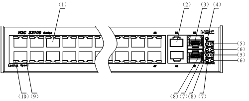
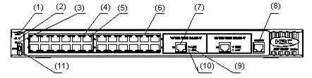
Each S3100-52TP-SI Ethernet switch provides forty-eight auto-sensing 10/100Base-TX Ethernet ports, two auto-sensing 10/100/1000Base-T Ethernet ports, and two 100/1000Base-X SFP ports on its front panel.
Figure 1-1 shows the front panel of an S3100-52TP-SI Ethernet switch.
Figure 1-1 Front panel of an S3100-52TP-SI Ethernet switch
|
(1) Auto-sensing 10/100Base-TX port |
(2) Auto-sensing 10/100/1000Base-T port |
|
(3) 100/1000Base-X SFP port |
(4) Power LED (Power) |
|
(5) SFP port Speed LED |
(6) SFP port LINK/ACT LED |
|
(7) 10/100/1000Base-T port LINK/ACT LED |
(8) 10/100/1000Base-T port Speed LED |
|
(9) 10/100Base-TX port Speed LED |
(10) 10/100Base-TX port LINK/ACT LED |
![]()
For details about LEDs on the front panel, refer to section “Front Panel LEDs of the S3100-TP-SI and S3100-TP-EI Series”.
Rear panel
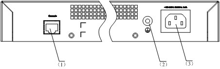
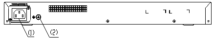
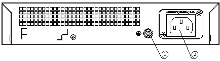
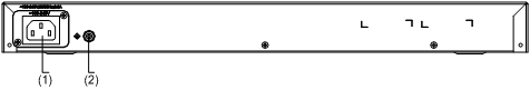
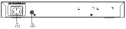
Each S3100-52TP-SI Ethernet switch provides one console port on its rear panel. Figure 1-25 shows the rear panel of an S3100-52TP-SI Ethernet switch.
Figure 1-2 Rear panel of an S3100-52TP-SI Ethernet switch
|
(1) Console port |
(2) Grounding screw |
|
(3) AC input terminal block |
|
Power system
S3100-52TP-SI Ethernet switches support AC input.
l Rated voltage range: 100 VAC to 240 VAC, 50 Hz/60 Hz
l Input voltage range: 90 VAC to 264 VAC, 47 Hz to 63 Hz
Cooling system
The S3100-52TP-SI cools off naturally.
S3100-26TP-SI
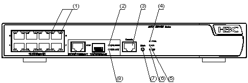
Front panel
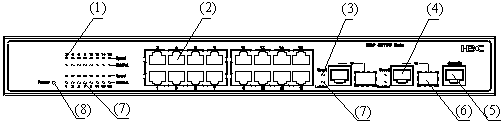
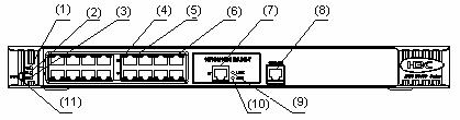
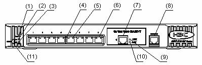
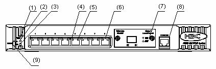
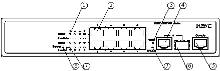
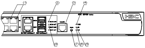
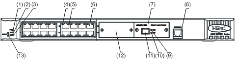
S3100-26TP-SI Ethernet switches each provide twenty-four auto-sensing 10/100Base-TX Ethernet ports, two auto-sensing 10/100/1000Base-T Ethernet ports, two 100/1000Base-X SFP ports, and one console port. Each SFP port and the corresponding auto-sensing 10/100/1000Base- T Ethernet port form a Combo port. For each Combo port, either the SFP port or the corresponding 10/100/1000Base-T Ethernet port can be used at a time.
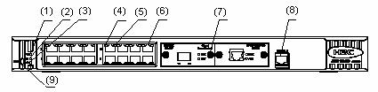
Figure 1-3 shows the front panel of an S3100-26TP-SI Ethernet switch.
Figure 1-3 Front panel of an S3100-26TP-SI Ethernet switch
|
(1) Auto-sensing 10/100Base-TX port Speed LED (green) |
|
|
(2) Auto-sensing 10/100Base-TX port |
(3) Combo port Speed LED (green) |
|
(4) Auto-sensing 10/100/1000Base-T port |
(5) Console port |
|
(6) 100/1000Base-X SFP port |
(7) LINK/ACT LED (green) |
|
(8) Power LED (PWR) |
|
![]()
For details about LEDs on the front panel, refer to section “Front Panel LEDs of the S3100-TP-SI and S3100-TP-EI Series”.
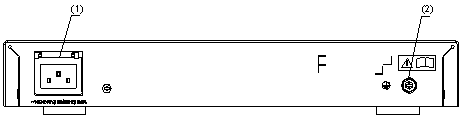
Rear panel
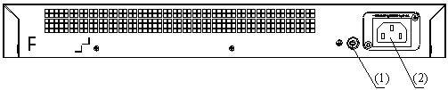
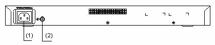
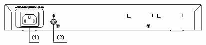
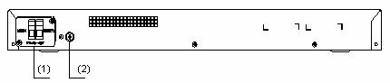
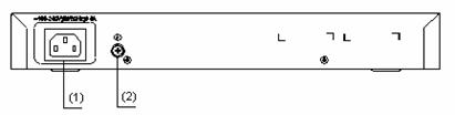
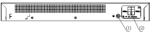
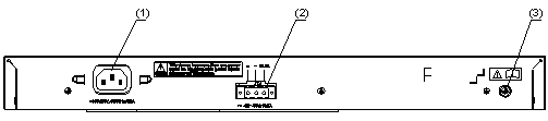
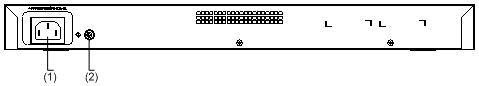
Figure 1-4 shows the rear panel of an S3100-26TP-SI Ethernet switch.
Figure 1-4 Rear panel of an S3100-26TP-SI Ethernet switch
|
(1) Grounding screw |
(2) AC input terminal block |
Power system
S3100-26TP-SI Ethernet switches support AC input.
l Rated voltage range: 100 VAC to 240 VAC, 50 Hz/60 Hz
l Input voltage range: 90 VAC to 264 VAC, 47 Hz to 63 Hz
Cooling system
The S3100-26TP-SI cools off naturally.
S3100-16TP-SI
Front panel
S3100-16TP-SI Ethernet switches each provide sixteen auto-sensing 10/100Base-TX Ethernet ports, two auto-sensing 10/100/1000Base-T Ethernet ports, two 100/1000Base-X SFP ports, and one console port. Each SFP port and the corresponding auto-sensing 10/100/1000Base- T Ethernet port form a Combo port. For each Combo port, either the SFP port or the corresponding 10/100/1000Base- T Ethernet port can be used at a time.
Figure 1-5 shows the front panel of an S3100-16TP-SI Ethernet switch.
Figure 1-5 Front panel of an S3100-16TP-SI Ethernet switch
|
(1) Auto-sensing 10/100Base-TX port Speed LED (green) |
|
|
(2) Auto-sensing 10/100Base-TX port |
(3) Combo port Speed LED (green) |
|
(4) Auto-sensing 10/100/1000Base-T port |
(5) Console port |
|
(6) 100/1000Base-X SFP port |
(7) LINK/ACT LED (green) |
|
(8) Power LED (PWR) |
|
![]()
For details about LEDs on the front panel, refer to section “Front Panel LEDs of the S3100-TP-SI and S3100-TP-EI Series”.
Rear panel
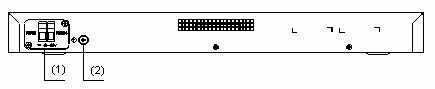
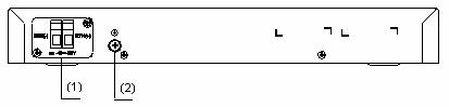
Figure 1-6 shows the rear panel of an S3100-16TP-SI Ethernet switch.
Figure 1-6 Rear panel of an S3100-16TP-SI Ethernet switch
|
(1) Grounding screw |
(2) AC input terminal block |
Power system
S3100-16TP-SI Ethernet switches support AC input.
l Rated voltage range: 100 VAC to 240 VAC, 50 Hz/60 Hz
l Input voltage range: 90 VAC to 264 VAC, 47 Hz to 63 Hz
Cooling system
The S3100-16TP-SI cools off naturally.
S3100-8TP-SI
Front panel
S3100-8TP-SI Ethernet switches each provide eight auto-sensing 10/100Base-TX Ethernet ports, one auto-sensing 10/100/1000Base-T Ethernet ports, one 100/1000Base-X SFP ports, and one console port. The SFP port and the auto-sensing 10/100/1000Base- T Ethernet port form a Combo port. For the Combo port, either the SFP port or the 10/100/1000Base- T Ethernet port can be used at a time.
Figure 1-7 shows the front panel of an S3100-8TP-SI Ethernet switch.
Figure 1-7 Front panel of an S3100-8TP-SI Ethernet switch
|
(1) Auto-sensing 10/100Base-TX port Speed LED (green) |
|
|
(2) Auto-sensing 10/100Base-TX port |
(3) Combo port Speed LED (green) |
|
(4) Auto-sensing 10/100/1000Base-T port |
(5) Console port |
|
(6) 100/1000Base-X SFP port |
(7) LINK/ACT LED (green) |
|
(8) Power LED (PWR) |
|
![]()
For details about LEDs on the front panel, refer to section “Front Panel LEDs of the S3100-TP-SI and S3100-TP-EI Series”.
Rear panel
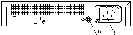
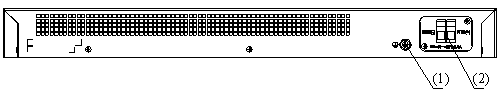
Figure 1-8 shows the rear panel of an S3100-8TP-SI Ethernet switch.
Figure 1-8 Rear panel of an S3100-8TP-SI Ethernet switch
|
(1) Grounding screw |
(2) AC input terminal block |
Power system
S3100-8TP-SI Ethernet switches support AC input.
l Rated voltage range: 100 VAC to 240 VAC, 50 Hz/60 Hz
l Input voltage range: 90 VAC to 264 VAC, 47 Hz to 63 Hz
Cooling system
The S3100-8TP-SI cools off naturally.
S3100-26T-SI
Front panel
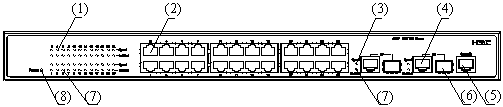
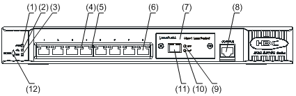
S3100-26T-SI Ethernet switches each provide twenty-four auto-sensing 10/100Base-TX Ethernet ports, two 10/100/1000Base-T Ethernet ports, and one console port. Figure 1-9 shows the front panel of an S3100-26T-SI Ethernet switch.
Figure 1-9 Front panel of an S3100-26T-SI Ethernet switch
|
(1) Power LED |
(2) A/L LED |
|
(3) D/S LED |
(4) Port status LED, left (yellow) |
|
(5) Port status LED, right (green) |
(6) 10/100 Base-TX port |
|
(7) 10/100/1000 Base-T port |
(8) Console port |
|
(9) LINK LED (green) |
(10) ACT LED (yellow) |
|
(11) Mode button |
|
![]()
For details about LEDs on the front panel, refer to section “Front Panel LEDs of the S3100-T-SI/S3100-C-SI/S3100-TP-PWR-EI/ S3100-C-EPON-EI Series”.
Rear panel
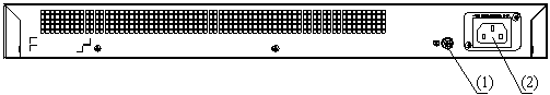
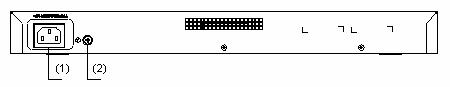
Figure 1-10 shows the rear panel of an S3100-26T-SI Ethernet switch.
Figure 1-10 Rear panel of an S3100-26T-SI Ethernet switch
|
(1) AC power socket |
(2) Grounding screw |
Power system
S3100-26T-SI Ethernet switches support AC input.
l Rated voltage range: 100 VAC to 240 VAC, 50 Hz/60 Hz
l Input voltage range: 90 VAC to 264 VAC, 47 Hz to 63 Hz
Cooling system
The S3100-26T-SI cools off naturally.
S3100-16T-SI
Front panel
S3100-16T-SI Ethernet switches each provide sixteen auto-sensing 10/100Base-TX Ethernet ports, one 10/100/1000Base-T Ethernet port, and one console port.
Figure 1-11 shows the front panel of an S3100-16T-SI Ethernet switch.
Figure 1-11 Front panel of an S3100-16T-SI Ethernet switch
|
(1) Power LED |
(2) A/L LED |
|
(3) D/S LED |
(4) Port status LED, left (yellow) |
|
(5) Port status LED, right (green) |
(6) 10/100 Base-TX port |
|
(7) 10/100/1000 Base-T port |
(8) Console port |
|
(9) LINK LED (green) |
(10) ACT LED (yellow) |
|
(11) Mode button |
|
![]()
For details about LEDs on the front panel, refer to section “Front Panel LEDs of the S3100-T-SI/S3100-C-SI/S3100-TP-PWR-EI/ S3100-C-EPON-EI Series”.
Rear panel
Figure 1-12 shows the rear panel of an S3100-16T-SI Ethernet switch.
Figure 1-12 Rear panel of an S3100-16T-SI Ethernet switch
|
(1) AC power socket |
(2) Grounding screw |
Power system
S3100-16T-SI Ethernet switches support AC input.
l Rated voltage range: 100 VAC to 240 VAC, 50 Hz/60 Hz
l Input voltage range: 90 VAC to 264 VAC, 47 Hz to 63 Hz
Cooling system
The S3100-16T-SI cools off naturally.
S3100-8T-SI
Front panel
S3100-8T-SI Ethernet switches each provide eight auto-sensing 10/100Base-TX Ethernet ports, one 10/100/1000Base-T Ethernet port, and one console port.
Figure 1-13 shows the front panel of an S3100-8T-SI Ethernet switch.
Figure 1-13 Front panel of an S3100-8T-SI Ethernet switch
|
(1) Power LED |
(2) A/L LED |
|
(3) D/S LED |
(4) Port status LED, left (yellow) |
|
(5) Port status LED, right (green) |
(6) 10/100 Base-TX port |
|
(7) 10/100/1000 Base-T port |
(8) Console port |
|
(9) LINK LED (green) |
(10) ACT LED (yellow) |
|
(11) Mode button |
|
![]()
For details about LEDs on the front panel, refer to section “Front Panel LEDs of the S3100-T-SI/S3100-C-SI/S3100-TP-PWR-EI/ S3100-C-EPON-EI Series”.
Rear panel
Figure 1-14 shows the rear panel of an S3100-8T-SI Ethernet switch.
Figure 1-14 Rear panel of an S3100-8T-SI Ethernet switch
|
(1) AC power socket |
(2) Grounding screw |
Power system
S3100-8T-SI Ethernet switches support AC input.
l Rated voltage range: 100 VAC to 240 VAC, 50 Hz/60 Hz
l Input voltage range: 90 VAC to 264 VAC, 47 Hz to 63 Hz
Cooling system
The S3100-8T-SI cools off naturally.
S3100-26C-SI
Both AC-powered switches and DC-powered switches are available to this model.
Front panel
S3100-26C-SI Ethernet switches each provide twenty-four auto-sensing 10/100Base-TX Ethernet ports, two expansion slots, and one console port.
S3100-26C-SI Ethernet switches have the same front panel, as shown in Figure 1-15.
Figure 1-15 Front panel of an S3100-26C-SI Ethernet switch
|
(1) Power LED |
(2) A/L LED |
|
(3) D/S LED |
(4) Port status LED, left (yellow) |
|
(5) Port status LED, right (green) |
(6) 10/100Base- TX port |
|
(7) Expansion slot |
(8) Console port |
|
(9) Mode button |
|
![]()
l With a PoE card inserted in one expansion slot, an S3100-26C-SI Ethernet switch will be a powered device (PD). In this case, the other expansion slot becomes unavailable.
l For details about LEDs on the front panel, refer to section “Front Panel LEDs of the S3100-T-SI/S3100-C-SI/S3100-TP-PWR-EI/ S3100-C-EPON-EI Series”.
Rear panel
Figure 1-16 shows the rear panel of an S3100-26C-SI AC-powered Ethernet switch.
Figure 1-16 Rear panel of an S3100-26C-SI AC-powered Ethernet switch
|
(1) AC power socket |
(2) Grounding screw |
Figure 1-17 shows the rear panel of an S3100-26C-SI DC-powered Ethernet switch.
Figure 1-17 Rear panel of an S3100-26C-SI DC-powered Ethernet switch
|
(1) DC input terminal block |
(2) Grounding screw |
Power system
1) S3100-26C-SI AC-powered Ethernet switches:
l Rated voltage range: 100 VAC to 240 VAC, 50 Hz/60 Hz
l Input voltage range: 90 VAC to 264 VAC, 47 Hz to 63 Hz
2) S3100-26C-SI DC-powered Ethernet switches:
l Rated voltage range: –48 VDC to –60 VDC
l Input voltage range: –36 VDC to –72 VDC
Cooling system
The S3100-26C-SI cools off naturally.
S3100-16C-SI
Both AC-powered switches and DC-powered switches are available to this model.
Front panel
S3100-16C-SI Ethernet switches each provide sixteen auto-sensing 10/100Base-TX Ethernet ports, two expansion slots, and one console port.
S3100-16C-SI Ethernet switches have the same front panel, as shown in Figure 1-18.
Figure 1-18 Front panel of an S3100-16C-SI Ethernet switch
|
(1) Power LED |
(2) A/L LED |
|
(3) D/S LED |
(4) Port status LED, left (yellow) |
|
(5) Port status LED, right (green) |
(6) 10/100Base- TX port |
|
(7) Expansion slot |
(8) Console port |
|
(9) Mode button |
|
![]()
l With a PoE card inserted in one expansion slot, an S3100-16C-SI Ethernet switch will be a powered device (PD). In this case, the other expansion slot becomes unavailable.
l For details about LEDs on the front panel, refer to section “Front Panel LEDs of the S3100-T-SI/S3100-C-SI/S3100-TP-PWR-EI/ S3100-C-EPON-EI Series”.
Rear panel
Figure 1-19 shows the rear panel of an S3100-16C-SI AC-powered Ethernet switch.
Figure 1-19 Rear panel of an S3100-16C-SI AC-powered Ethernet switch
|
(1) AC power socket |
(2) Grounding screw |
Figure 1-20 shows the rear panel of an S3100-16C-SI DC-powered Ethernet switch.
Figure 1-20 Rear panel of an S3100-16C-SI DC-powered Ethernet switch
|
(1) DC input terminal block |
(2) Grounding screw |
Power system
1) S3100-16C-SI AC-powered Ethernet switches:
l Rated voltage range: 100 VAC to 240 VAC, 50 Hz/60 Hz
l Input voltage range: 90 VAC to 264 VAC, 47 Hz to 63 Hz
2) S3100-16C-SI DC-powered Ethernet switches:
l Rated voltage range: –48 VDC to –60 VDC
l Input voltage range: –36 VDC to –72 VDC
Cooling system
The S3100-16C-SI cools off naturally.
S3100-8C-SI
Both AC-powered switches and DC-powered switches are available to this model.
Front panel
S3100-8C-SI Ethernet switches each provide eight auto-sensing 10/100Base-TX Ethernet ports, one expansion slot, and one console port.
S3100-8C-SI Ethernet switches have the same front panel, as shown in Figure 1-21.
Figure 1-21 Front panel of an S3100-8C-SI Ethernet switch
|
(1) Power LED |
(2) A/L LED |
|
(3) D/S LED |
(4) Port status LED, left (yellow) |
|
(5) Port status LED, right (green) |
(6) 10/100Base- TX port |
|
(7) Expansion slot |
(8) Console port |
|
(9) Mode button |
|
![]()
For details about LEDs on the front panel, refer to section “Front Panel LEDs of the S3100-T-SI/S3100-C-SI/S3100-TP-PWR-EI/ S3100-C-EPON-EI Series”.
Rear panel
Figure 1-22 shows the rear panel of an S3100-8C-SI AC-powered Ethernet switch.
Figure 1-22 Rear panel of an S3100-8C-SI AC-powered Ethernet switch
|
(1) AC power socket |
(2) Grounding screw |
Figure 1-23 shows the rear panel of an S3100-8C-SI DC-powered Ethernet switch.
Figure 1-23 Rear panel of an S3100-8C-SI DC-powered Ethernet switch
|
(1) DC input terminal block |
(2) Grounding screw |
Power system
1) S3100-8C-SI AC-powered Ethernet switches:
l Rated voltage range: 100 VAC to 240 VAC, 50 Hz/60 Hz
l Input voltage range: 90 VAC to 264 VAC, 47 Hz to 63 Hz
2) S3100-8C-SI DC-powered Ethernet switches:
l Rated voltage range: –48 VDC to –60 VDC
l Input voltage range: –36 VDC to –72 VDC
Cooling system
The S3100-8C-SI cools off naturally.
Introduction to S3100-EI Series Ethernet Switches
S3100-26TP-EI
Both AC-powered switches and DC-powered switches are available to this model.
Front panel
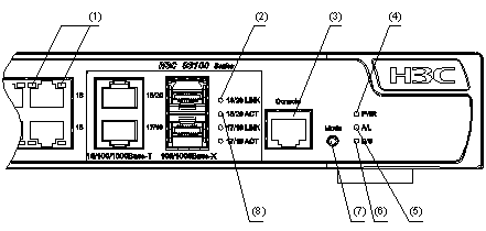
S3100-26TP-EI Ethernet switches each provide twenty-four auto-sensing 10/100Base-TX Ethernet ports, two auto-sensing 10/100/1000Base-T Ethernet ports, two 100/1000Base-X SFP ports, and one console port. Each SFP port and the corresponding auto-sensing 10/100/1000Base- T Ethernet port form a Combo port. For each Combo port, either the SFP port or the corresponding 10/100/1000Base- T Ethernet port can be used at a time.
S3100-26TP-EI Ethernet switches have the same front panel, as shown in Figure 1-24.
Figure 1-24 Front panel of an S3100-26TP-EI Ethernet switch
|
(1) Auto-sensing 10/100Base-TX port Speed LED (green) |
|
|
(2) Auto-sensing 10/100Base-TX port |
(3) Combo port Speed LED (green) |
|
(4) Auto-sensing 10/100/1000Base-T port |
(5) Console port |
|
(6) 100/1000Base-X SFP port |
(7) LINK/ACT LED (green) |
|
(8) Power LED (PWR) |
|
![]()
For details about LEDs on the front panel, refer to section “Front Panel LEDs of the S3100-TP-SI and S3100-TP-EI Series”.
Rear panel
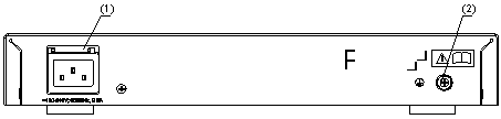
Figure 1-25 shows the rear panel of an S3100-26TP-EI AC-powered Ethernet switch.
Figure 1-25 Rear panel of an S3100-26TP-EI AC-powered Ethernet switch
|
(1) Grounding screw |
(2) AC input terminal block |
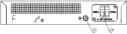
Figure 1-26 shows the rear panel of an S3100-26TP-EI DC-powered Ethernet switch.
Figure 1-26 Rear panel of an S3100-26TP-EI DC-powered Ethernet switch
|
(1) Grounding screw |
(2) DC input terminal block |
Power system
1) S3100-26TP-EI AC-powered Ethernet switches:
l Rated voltage range: 100 VAC to 240 VAC, 50 Hz/60 Hz
l Input voltage range: 90 VAC to 264 VAC, 47 Hz to 63 Hz
2) S3100-26TP-EI DC-powered Ethernet switches:
l Rated voltage range: –48 VDC to –60 VDC
l Input voltage range: –36 VDC to –72 VDC
Cooling system
The S3100-26TP-EI cools off naturally.
S3100-16TP-EI
Both AC-powered switches and DC-powered switches are available to this model.
Front panel
S3100-16TP-EI Ethernet switches each provide sixteen auto-sensing 10/100Base-TX Ethernet ports, two auto-sensing 10/100/1000Base-T Ethernet ports, two 100/1000Base-X SFP ports, and one console port. Each SFP port and the corresponding auto-sensing 10/100/1000Base- T Ethernet port form a Combo port. For each Combo port, either the SFP port or the corresponding 10/100/1000Base- T Ethernet port can be used at a time.
S3100-16TP-EI Ethernet switches have the same front panel, as shown in Figure 1-27.
Figure 1-27 Front panel of an S3100-16TP-EI Ethernet switch
|
(1) Auto-sensing 10/100Base-TX port Speed LED (green) |
|
|
(2) Auto-sensing 10/100Base-TX port |
(3) Combo port Speed LED (green) |
|
(4) Auto-sensing 10/100/1000Base-T port |
(5) Console port |
|
(6) 100/1000Base-X SFP port |
(7) LINK/ACT LED (green) |
|
(8) Power LED (PWR) |
|
![]()
For details about LEDs on the front panel, refer to section “Front Panel LEDs of the S3100-TP-SI and S3100-TP-EI Series”.
Rear panel
Figure 1-28 shows the rear panel of an S3100-16TP-EI AC-powered Ethernet switch.
Figure 1-28 Rear panel of an S3100-16TP-EI AC-powered Ethernet switch
|
(1) Grounding screw |
(2) AC input terminal block |
Figure 1-29 shows the rear panel of an S3100-16TP-EI DC-powered Ethernet switch.
Figure 1-29 Rear panel of an S3100-16TP-EI DC-powered Ethernet switch
|
(1) Grounding screw |
(2) DC input terminal block |
Power system
1) S3100-16TP-EI AC-powered Ethernet switches:
l Rated voltage range: 100 VAC to 240 VAC, 50 Hz/60 Hz
l Input voltage range: 90 VAC to 264 VAC, 47 Hz to 63 Hz
2) S3100-16TP-EI DC-powered Ethernet switches:
l Rated voltage range: –48 VDC to –60 VDC
l Input voltage range: –36 VDC to –72 VDC
Cooling system
The S3100-16TP-EI cools off naturally.
S3100-8TP-EI
Both AC-powered switches and DC-powered switches are available to this model.
Front panel
S3100-8TP-EI Ethernet switches each provide eight auto-sensing 10/100Base-TX Ethernet ports, one auto-sensing 10/100/1000Base-T Ethernet ports, one 100/1000Base-X SFP ports, and one console port. The SFP port and the auto-sensing 10/100/1000Base- T Ethernet port form a Combo port. For the Combo port, either the SFP port or the 10/100/1000Base- T Ethernet port can be used at a time.
S3100-8TP-EI Ethernet switches have the same front panel, as shown in Figure 1-30.
Figure 1-30 Front panel of an S3100-8TP-EI Ethernet switch
|
(1) Auto-sensing 10/100Base-TX port Speed LED (green) |
|
|
(2) Auto-sensing 10/100Base-TX port |
(3) Combo port Speed LED (green) |
|
(4) Auto-sensing 10/100/1000Base-T port |
(5) Console port |
|
(6) 100/1000Base-X SFP port |
(7) LINK/ACT LED (green) |
|
(8) Power LED (PWR) |
|
![]()
For details about LEDs on the front panel, refer to section “Front Panel LEDs of the S3100-TP-SI and S3100-TP-EI Series”.
Rear panel
Figure 1-31 shows the rear panel of an S3100-8TP-EI AC-powered Ethernet switch.
Figure 1-31 Rear panel of an S3100-8TP-EI AC-powered Ethernet switch
|
(1) Grounding screw |
(2) AC input terminal block |
Figure 1-32 shows the rear panel of an S3100-8TP-EI DC-powered Ethernet switch.
Figure 1-32 Rear panel of an S3100-8TP-EI DC-powered Ethernet switch
|
(1) Grounding screw |
(2) DC input terminal block |
Power system
1) S3100-8TP-EI AC-powered Ethernet switches:
l Rated voltage range: 100 VAC to 240 VAC, 50 Hz/60 Hz
l Input voltage range: 90 VAC to 264 VAC, 47 Hz to 63 Hz
2) S3100-8TP-EI DC-powered Ethernet switches:
l Rated voltage range: –48 VDC to –60 VDC
l Input voltage range: –36 VDC to –72 VDC
Cooling system
The S3100-8TP-EI cools off naturally.
S3100-26TP-PWR-EI
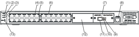
Front panel
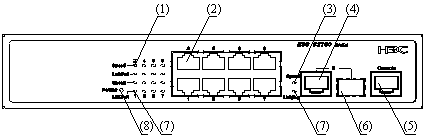
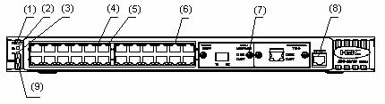
S3100-26TP-PWR-EI Ethernet switches each provide twenty-four auto-sensing 10/100Base-TX Ethernet ports, two 10/100/1000Base-T Ethernet ports, two 100/1000Base SFP ports, and one console port. Each SFP port and the corresponding 10/100/1000Base- T Ethernet port form a Combo port. For each Combo port, either the SFP port or the corresponding 10/100/1000Base- T Ethernet port can be used at a time. Figure 1-33 shows the front panel of an S3100-26TP-PWR-EI Ethernet switch.
Figure 1-33 Front panel of an S3100-26TP-PWR-EI Ethernet switch
|
(1) Auto-sensing 10/100Base-TX Ethernet port status LED |
|
|
(2) LINK LED for Combo port |
(3) Console port |
|
(4) Power LED (PWR) |
(5) A/L LED |
|
(6) D/S LED |
(7) Mode button |
|
(8) ACT LED for Combo port |
|
![]()
For details about LEDs on the front panel, refer to section “Front Panel LEDs of the S3100-T-SI/S3100-C-SI/S3100-TP-PWR-EI/ S3100-C-EPON-EI Series”.
Rear panel
Figure 1-34 Rear panel of an S3100-26TP-PWR-EI Ethernet switch
|
(1) AC power socket |
(2) DC power socket |
|
(3) Grounding screw |
|
Power system
S3100-26TP-PWR-EI Ethernet switches support AC input or DC input.
1) AC input
l Rated voltage range: 100 VAC to 240 VAC, 50 Hz/60 Hz
l Input voltage range: 90 VAC to 264 VAC, 47 Hz to 63 Hz
2) DC input
l Rated voltage range: –52 VDC to –56 VDC
![]()
Only the recommended RPS can be used for S3100-26TP-PWR-EI Ethernet switches. The –48 VDC in the equipment room cannot be used directly. Otherwise, the device may be damaged.
Cooling system
The S3100-26TP-PWR-EI has four fans for heat dissipation.
S3100-16TP-PWR-EI
Front panel
S3100-16TP-PWR-EI Ethernet switches each provide sixteen auto-sensing 10/100Base-TX Ethernet ports, two 10/100/1000Base-T Ethernet ports, two 100/1000Base SFP ports, and one console port. Each SFP port and the corresponding 10/100/1000Base-T Ethernet port form a Combo port. For each Combo port, either the SFP port or the corresponding 10/100/1000Base-T Ethernet port can be used at a time.
Figure 1-35 shows the front panel of an S3100-16TP-PWR-EI Ethernet switch.
Figure 1-35 Front panel of an S3100-16TP-PWR-EI Ethernet switch
|
(1) Auto-sensing 10/100Base-TX Ethernet port status LED |
|
|
(2) LINK LED for Combo port |
(3) Console port |
|
(4) Power LED (PWR) |
(5) A/L LED |
|
(6) D/S LED |
(7) Mode button |
|
(8) ACT LED for Combo port |
|
![]()
For details about LEDs on the front panel, refer to section “Front Panel LEDs of the S3100-T-SI/S3100-C-SI/S3100-TP-PWR-EI/ S3100-C-EPON-EI Series”.
Rear panel
Figure 1-36 Rear panel of an S3100-16TP-PWR-EI Ethernet switch
|
(1) AC power socket |
(2) Grounding screw |
Side panel
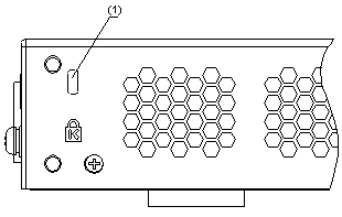
Each S3100-16TP-PWR-EI Ethernet switch provides a security slot, through which you can lock the device together with an irremovable object to prevent theft.
The security slot is located at the rear end of the left side panel, as shown in Figure 1-37.
Figure 1-37 Security slot on left side panel of an S3100-16TP-PWR-EI Ethernet switch
|
(1) Security slot |
![]()
If the left screw hole above the security slot is used, the security slot cannot be used.
Power system
S3100-16TP-PWR-EI Ethernet switches support AC input.
l Rate voltage range: 100 VAC to 240 VAC, 50 Hz/60 Hz
l Input voltage range: 90 VAC to 264 VAC, 47 Hz to 63 Hz
Cooling system
The S3100-16TP-PWR-EI has two fans for heat dissipation.
S3100-8TP-PWR-EI
Front panel
S3100-8TP-PWR-EI Ethernet switches each provide eight auto-sensing 10/100Base-TX Ethernet ports, one 10/100/1000Base-T Ethernet port, one 100/1000Base SFP ports, and one console port. The SFP port and the 10/100/1000Base-T Ethernet port form a Combo port. Either the SFP port or the 10/100/1000Base-T Ethernet port can be used at a time.
Figure 1-38 shows the front panel of an S3100-8TP-PWR-EI Ethernet switch.
Figure 1-38 Front panel of an S3100-8TP-PWR-EI Ethernet switch
|
(1) Auto-sensing 10/100Base-TX Ethernet port status LED |
|
|
(2) LINK LED for Combo port |
(3) Console port |
|
(4) Power LED (PWR) |
(5) A/L LED |
|
(6) D/S LED |
(7) Mode button |
|
(8) ACT LED for Combo port |
|
![]()
For details about LEDs on the front panel, refer to section “Front Panel LEDs of the S3100-T-SI/S3100-C-SI/S3100-TP-PWR-EI/ S3100-C-EPON-EI Series”.
Rear panel
Figure 1-39 Rear panel of an S3100-8TP-PWR-EI Ethernet switch
|
(1) AC power socket |
(2) Grounding screw |
Side panel
Each S3100-8TP-PWR-EI Ethernet switch provides a security slot, through which you can lock the device together with an irremovable object to prevent theft. The security slot is located at the rear end of the left side panel, as shown in Figure 1-37.
![]()
If the left screw hole above the security slot is used, the security slot cannot be used.
Power system
S3100-8TP-PWR-EI Ethernet switches support AC input.
l Rate voltage range: 100 VAC to 240 VAC, 50 Hz/60 Hz
l Input voltage range: 90 VAC to 264 VAC, 47 HZ to 63 Hz
Cooling system
The S3100-8TP-PWR-EI has two fans for heat dissipation.
S3100-26C-EPON-EI
Front panel
The S3100-26C-EPON-EI provides 24 x 10/100Base-TX ports, one Gigabit uplink PON port, one expansion slot, and one console port.
Figure 1-40 shows the front view of the S3100-26C-EPON-EI.
Figure 1-40 Front panel of the S3100-26C-EPON-EI
|
(1) Power Led (PWR) |
(2) A/L LED |
|
(3) D/S LED |
(4) Port status LED, left (yellow) |
|
(5) Port status LED, right (green) |
(6) 10/100 Base-TX port |
|
(7) ONU module |
(8) Console port |
|
(9) LINK LED for the uplink PON port |
(10) ACT LED for the uplink PON port |
|
(11) 1000 Mbps uplink PON port |
(12) Expansion slot |
|
(13) MODE button |
|
![]()
l The S3100-26C-EPON-EI provides one expansion slot. You can order one more ONU module (1000Base- PX20) as needed. For more information about ONU modules, refer to section “ONU Modules”.
l For details about the LEDs on the front panel, refer to section “Front Panel LEDs of the S3100-T-SI/S3100-C-SI/S3100-TP-PWR-EI/ S3100-C-EPON-EI Series”.
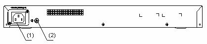
Rear panel
Figure 1-41 Rear panel of an S3100-26C-EPON-EI Ethernet switch
|
(1) AC power socket |
(2) Grounding screw |
Power system
S3100-26C-EPON-EI Ethernet switches support AC input.
l Rated voltage range: 100 VAC to 240 VAC, 50 Hz/60 Hz
l Input voltage range: 90 VAC to 264 VAC, 47 Hz to 63 Hz
Cooling system
The S3100-26C-EPON-EI has one fan for heat dissipation.
S3100-16C-EPON-EI
Front panel
The S3100-16C-EPON-EI provides 16 x 10/100Base-TX Ethernet ports, one 1000 Mbps uplink PON port, and one console port.
Figure 1-42 shows the front panel of the S3100-16C-EPON-EI.
Figure 1-42 Front panel of the S3100-16C-EPON-EI
|
(1) Power Led (PWR) |
(2) A/L LED |
|
(3) D/S LED |
(4) Port status LED, left (yellow) |
|
(5) Port status LED, right (green) |
(6) 10/100 Base-TX port |
|
(7) ONU module |
(8) Console port |
|
(9) LINK LED for the uplink PON port |
(10) ACT LED for the uplink PON port |
|
(11) 1000 Mbps uplink PON port |
(12) Expansion slot (disabled) |
|
(13) MODE button |
|
![]()
l The S3100-16C-EPON-EI supports only one ONU module (required).
l For details about the LEDs on the front panel, refer to section “Front Panel LEDs of the S3100-T-SI/S3100-C-SI/S3100-TP-PWR-EI/ S3100-C-EPON-EI Series”.
Rear panel
Figure 1-43 Rear panel of an S3100-16C-EPON-EI Ethernet switch
|
(1) AC power socket |
(2) Grounding screw |
Power system
S3100-16C-EPON-EI Ethernet switches support AC input.
l Rated voltage range: 100 VAC to 240 VAC, 50 Hz/60 Hz
l Input voltage range: 90 VAC to 264 VAC, 47 Hz to 63 Hz
Cooling system
The S3100-16C-EPON-EI cools off naturally.
S3100-8C-EPON-EI
Front panel
The S3100-8C-SI provides 8 x 10/100Base-TX Ethernet ports, one 1000 Mbps uplink PON port, and one console port.
Figure 1-44 shows the front panel of the S3100-8C-EPON-EI.
Figure 1-44 Front panel of the S3100-8C-EPON-EI
|
(1) Power LED (PWR) |
(2) A/L LED |
|
(3) D/S LED |
(4) Port status LED, left (yellow) |
|
(5) Port status LED, right (green) |
(6) 10/100 Base-TX port |
|
(7) ONU module |
(8) Console port |
|
(9) Link LED for the uplink PON port |
(10) ACT LED for the uplink PON port |
|
(11) 1000 Mbps uplink PON port |
(12) MODE button |
![]()
For details about the LEDs on the front panel, refer to section “Front Panel LEDs of the S3100-T-SI/S3100-C-SI/S3100-TP-PWR-EI/ S3100-C-EPON-EI Series”.
Rear panel
Figure 1-45 Rear panel of an S3100-8C-EPON-EI Ethernet switch
|
(1) AC power socket |
(2) Grounding screw |
Power system
S3100-8C-EPON-EI Ethernet switches support AC input.
l Rated voltage range: 100 VAC to 240 VAC, 50 Hz/60 Hz
l Input voltage range: 90 VAC to 264 VAC, 47 Hz to 63 Hz
Cooling system
The S3100-8C-EPON-EI cool off naturally.
Introduction to Front Panel LEDs
Front Panel LEDs of the S3100-T-SI/S3100-C-SI/S3100-TP-PWR-EI/ S3100-C-EPON-EI Series
Power LED
Table 1-8 Description of the power LED on S3100-T-SI, S3100-C-SI, S3100-TP-PWR-EI and S3100-C-EPON-EI series Ethernet switches
|
LED |
Mark on the panel |
Status |
Description |
|
Power LED |
PWR |
ON |
The switch is powered on. |
|
OFF |
The switch is powered off. |
Auto-sensing 10/100Base- TX Ethernet port status LED
There are two port status LEDs on both sides (yellow LED on the left and green LED on the right) of each 10/100Base-TX Ethernet port of S3100-T-SI, S3100-C-SI, S3100-TP-PWR-EI and S3100-C-EPON-EI series. They indicate the active, link, duplex, and speed statuses of the port.
In addition, there are an A/L LED and a D/S LED on each model of S3100-T-SI, S3100-C-SI, S3100-TP-PWR-EI and S3100-C-EPON-EI series. These two LEDs indicate the mode of the port status LEDs. When the A/L LED is on, the port status LEDs respectively indicate the active status and link status of ports. When the D/S LED is on, the port status LEDs respectively indicate the duplex status and speed status of ports. Either the A/L LED or the D/S LED is on at a specific time. For details, see Table 1-9.
Table 1-9 Description of port status LEDs on S3100-T-SI, S3100-C-SI, S3100-TP-PWR-EI, and S3100-C-EPON-EI series Ethernet switches
|
Port status mode LED |
Port status LED |
Description |
|
|
The A/L LED is on |
Yellow LED (left) |
Blinking |
The port is in the active state and there is traffic on the port. |
|
OFF |
The port is in the active state but there is no traffic on the port. |
||
|
Green LED (right) |
ON |
The port is connected properly. |
|
|
OFF |
The port is not connected or is incorrectly connected. |
||
|
The D/S LED is on |
Yellow LED (left) |
ON |
The port operates in the full duplex mode. |
|
OFF |
The port operates in the half duplex mode. |
||
|
Green LED (right) |
ON |
The port rate is 100 Mbps. |
|
|
OFF |
The port rate is 10 Mbps. |
||
You can switch the mode of the port status LEDs by pressing the Mode button. After a switch is powered on, the A/L LED is on initially. If you press the Mode button, the D/S LED will be on. After that, if you press the Mode button again within 45 seconds, the A/L LED will be on again. Otherwise, the A/L LED will automatically be on 45 seconds later.
1000 Mbps Uplink Port Status LED
Table 1-10 Description of 1000 Mbps uplink port status LED on S3100-T-SI, S3100-C-SI, S3100-TP-PWR-EI and S3100-C-EPON-EI series Ethernet switches
|
LED |
Mark on the panel |
Status |
Description |
|
1000 Mbps uplink port link LED |
LINK |
ON |
The port is connected properly. |
|
OFF |
The port is not connected or is incorrectly connected. |
||
|
1000 Mbps uplink port active LED |
ACT |
Blinking |
The port is in the active state and there is traffic on the port. |
|
OFF |
The port is in the active state but there is no traffic on the port. |
Front Panel LEDs of the S3100-TP-SI and S3100-TP-EI Series
Power LED
Table 1-11 Description of the power LED on the S3100-TP-SI and S3100-TP-EI series
|
LED |
Mark on the panel |
Status |
Description |
|
Power LED |
Power |
ON |
The switch is powered on. |
|
OFF |
The switch is powered off. |
Port Status LED
Table 1-12 describes the Link/Act LED of the auto-sensing 10/100Base-TX port.
Table 1-12 Description of the Link/Act LED on the S3100-TP-SI and S3100-TP-EI series
|
LED |
Status |
Description |
|
Link/Act LED (green) |
ON |
The port is connected properly. |
|
Blinking |
The port is in the active state and there is traffic on the port. |
|
|
OFF |
The port is not connected or is incorrectly connected. |
Table 1-13 describes the Speed LED of the 10/100Base-TX port.
Table 1-13 Description of the 10/100Base-TX port Speed LED of the S3100-TP-SI and S3100-TP-EI series
|
LED |
Status |
Description |
|
Auto-sensing 10/100Base-TX port speed LED (green) |
ON |
The port is operating at 100 Mbps. |
|
OFF |
The port is operating at 10 Mbps. |
For the description of the Link/Act LED of the Combo port on the S3100-TP-SI and the S3100-TP-EI series, see Table 1-12. When the port is connected correctly, the Speed LED indicates the operating speeds of the Combo port, as shown in Table 1-14.
Table 1-14 Description of the Combo port Speed LED of the S3100-TP-SI and the S3100-TP-EI series
|
LED |
Operating port |
Status |
Description |
|
|
Combo port Speed LED (green) |
100/1000Base-X SFP port |
Connected to a 1000 Mbps optical module |
ON |
The port is operating at 1000 Mbps. |
|
Connected to a 100 Mbps optical module |
OFF |
The port is operating at 100 Mbps. |
||
|
Auto-sensing 10/100/1000Base-T port |
ON |
The port is operating at 1000 Mbps. |
||
|
OFF |
The port is operating at 10/100 Mbps. |
|||
For the description of the Link/Act LED of the 100/1000Base-X SFP port and Auto-sensing 10/100/1000Base-T port on the S3100-52TP-SI, see Table 1-12. When the port is connected correctly, the Speed LED indicates the operating speeds of the port, as shown in Table 1-15.
|
LED |
Status |
Description |
|
|
100/1000Base-X SFP port |
Connected to a 1000 Mbps optical module |
ON |
The port is operating at 1000 Mbps. |
|
Connected to a 100 Mbps optical module |
OFF |
The port is operating at 100 Mbps. |
|
|
Auto-sensing 10/100/1000Base-T port |
ON |
The port is operating at 1000 Mbps. |
|
|
OFF |
The port is operating at 10/100 Mbps. |
||
SFP Modules Supported by S3100 Ethernet Switches
The front panel of S3100-TP-SI, S3100-TP-EI and S3100-TP-PWR-EI Ethernet switches provides one or two 1000 Mbps SFP ports in which you can select the required small form-factor pluggable (SFP) modules to insert. For the models of SFP modules, see Table 1-16.
Table 1-16 SFP modules supported by S3100 Ethernet switches
|
Type |
Model |
|
|
SFP module |
100 Mbps SFP module |
l SFP-FE-SX-MM1310-A l SFP-FE-LX-SM1310-A |
|
1000 Mbps SFP module |
l SFP-GE-SX-MM850-A l SFP-GE-LX-SM1310-A |
|
|
SFP stack module |
SFP-STACK-Kit |
|
|
100 Mbps bidirectional (BIDI) module |
l SFP-FE-LX-SM1310-BIDI l SFP-FE-LX-SM1550-BIDI |
|
|
1000 Mbps BIDI module |
l SFP-GE-LX-SM1310-BIDI l SFP-GE-LX-SM1490-BIDI |
|
![]()
l The types of SFP modules may vary over time. Consult H3C marketing personnel or technical support personnel to obtain the latest information about SFP modules.
l For specifications of SFP modules, refer to H3C Low End Series Ethernet Switches Pluggable Module Manual.
ONU Modules
When equipped with one or two ONU modules, the S3100-C-SI and S3100-C-EPON-EI series can serve as ONU devices. Table 1-17 shows the ONU module support of the S3100 series.
Table 1-17 ONU module support of the S3100 series
|
Switch model |
Number of ONU modules |
Required or optional |
ONU module model |
|
S3100-8C-SI |
1 |
Optional |
l 1000Base-PX10 (LS6M1PU1SA) l 1000Base-PX20 (LS6M1PU1SB) |
|
S3100-16C-SI |
1 |
Optional |
|
|
S3100-26C-SI |
1 |
Optional |
|
|
S3100-8C-EPON-EI |
1 |
Required |
1000Base-PX20 (LS6M2PU1SB) |
|
S3100-16C-EPON-EI |
1 |
Required |
|
|
S3100-26C-EPON-EI |
2 |
1 required 1 optional |
All models of ONU modules look alike. Figure 1-46 and Figure 1-47 depict the LS6M2PU1SB.
Figure 1-46 Appearance of the LS6M2PU1SB
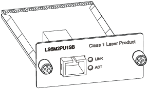
Figure 1-47 Front panel of the LS6M2PU1SB
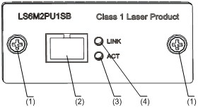
|
(1) Fastening screws |
(2) 1000 Mbps PON port |
|
(3) ACT LED of the PON port |
(4) LINK LED for the PON port |
The ONU module provides one 1000 Mbps uplink PON port. Table 1-18 lists the technical specifications for the PON port.
Table 1-18 Technical specifications for the ONU port
|
Item |
Specifications |
|
Connector type |
SC |
|
Number of interfaces |
1 |
|
Interface speed |
1000 Mbps |
|
Medium |
9/125 µm single-mode fiber |
|
Maximum transmission distance |
l 1000Base- PX10: 10 km (6.21 miles) l 1000Base- PX20: 20 km (12.43 miles) |
For how to install and remove an ONU module, refer to section ”Installing an Expansion Interface Module”. Table 1-19 describes the LED indications.
Table 1-19 Description of ONU module LEDs
|
LED |
Status |
Meaning |
|
LINK |
ON |
The port is connected properly. |
|
OFF |
The port has no connectivity or is incorrectly connected. |
|
|
ACT |
Blinking |
The port is in active state and there is traffic on it. |
|
OFF |
The port is in active state but there is no traffic on it. |
2 Installation Preparation
Precautions
To avoid any device impairment and body injury resulting from improper use, please take the following precautions:
l Before cleaning the switch, disconnect the power. Do not clean the switch with wet cloth or liquid.
l Keep the switch away from water or dampness. Prevent water or moisture from entering the switch chassis.
l Do not place the switch on an unstable case or desk, because the switch might be damaged severely in case of a fall.
l Keep the switch room drafty and the switch ventilation hole free of obstruction.
l The switch can operate normally only under correct voltage input. Make sure that the operating voltage is consistent with that labeled on the switch.
l To prevent electric shock, do not open the chassis while the switch is operating, and do not open the chassis arbitrarily even when the switch is powered off.
l Before changing interface cards, wear an ESD-preventive wrist strap to prevent the cards from being damaged by electrostatic discharge.
Requirements on Environment
S3100 Series Ethernet Switches must be used indoors. When you install your switch in a cabinet or on a desk, you must ensure:
l Enough space is reserved near the air-intake hole and the ventilation hole of the switch for heat dissipation of the switch chassis.
l The cabinet or the workbench takes good ventilation and heat dissipation system.
l The cabinet or the desk is solid enough to bear the weight of the switch and the accessories.
l The cabinet or the desk is well grounded.
To ensure normal operation and to prolong the life span of the switch, the following requirements on the installation site must also be satisfied.
Temperature/Humidity Requirements
You should keep your equipment room within the proper temperature and humidity ranges to ensure the normal operation and working life of your switch. If the humidity in the equipment room is too high for a long time, it may decrease the insulation attribute of insulating material or even cause electric leakage of insulating material, and, sometimes, may change the mechanical performance of material and cause the rustiness and corrosion of metal parts. If the relative humidity is too low, the captive screws may become loose due to the shrinking of insulation washers; in addition, electrostatic is more likely to be produced in a dry environment, which may damage the circuit of the switch. High temperature may cause even greater damage to the switch. High temperature for a long time will speed up the aging of insulation material, greatly lower the reliability of the switch and greatly reduce the life span of the switch.
For the temperature and humidity requirements of different models, refer to section “Overview”.
Cleanness Requirements
Dust is a potential hazard to the safe operation of the switch. Falling on the equipment, it may cause electrostatic adsorption, and hence result in poor contact of the metal connectors or connection points. This is more likely to happen when the indoor relative humidity is low; in this case, it may not only shorten the device’s working life, but also incur communication failure. The requirements on dust content and particle diameter in the equipment room are shown in the following table:
Table 2-1 Requirements on dust content in the equipment room
|
Physical active substance |
Unit |
Content |
|
Dust particle |
particle/m³ |
≤ 3 × 10⁴ (No visible dust on desk in three days) |
|
Note: Dust particle diameter ≥ 5µm |
||
Besides the requirements on dust, rigorous requirements are also set on the content of chloride, acid, and sulfide in the air of the equipment room. These kinds of harmful gas will accelerate metal corrosion and aging of certain parts. The equipment room should be protected from the intrusion of harmful gases such as SO2, H2S, NH3 and Cl2. The limits of these kinds of harmful gas are shown in the following table.
Table 2-2 Limits on harmful gas in the equipment room
|
Gas |
Max content (mg/m³) |
|
SO2 |
0.2 |
|
H2S |
0.006 |
|
NH3 |
0.05 |
|
Cl2 |
0.01 |
Anti-interference Requirements
A switch in use may be affected by the interference from outside the system by way of capacitance coupling, inductance coupling, electromagnetic radiation, public impedance (including the grounding system) coupling or conducting line (power line, signaling line, and transmission line). Therefore, you should pay attention to the following:
l If AC supply system is TN system, AC power socket should be a single-phase three-line power socket with Protection Earth (PE) so that the filter circuit on the equipment can effectively filter out the interference coming from the power supply system.
l Keep the switch far away from high-power radio transmitters, radars, and high-frequency heavy-current devices.
l Adopt electromagnetic shielding measure if necessary. For example, you can adopt shielded interface cable.
l Wire interface cables indoors. Do not wire cables outdoors in case that over-voltage and over-current damage the device.
Laser Usage Security
S3100 Series Ethernet Switches are category-1 laser equipment.
![]()
When an optional interface card of the S3100 Series Ethernet Switches is operating, avoid staring into the optical interface because the high-energy laser beam emitted from the optical fiber may hurt your eyes.
Installation Tools
![]()
These installation tools are not shipped with S3100 Series Ethernet Switches. You will have to prepare them beforehand.
l Phillips screwdriver
l Flat-blade screwdriver
l ESD-preventive wrist strap
![]()
On a mounting screw of the chassis of the H3C S3100 Series Ethernet Switches, there is a seal labeled with H3C. You must keep it intact before asking the agent to maintain the switch. You must get the permission of the local agent before you can open the chassis. Otherwise, you will be responsible for irreversible damages caused by your operations.
Installing a Switch
Cabinet Mounting
You can install a switch into a 19-inch standard cabinet in one of the following four ways:
l Use front mounting ears
l Use front mounting ears and a tray
l Use front mounting ears and rear mounting ears
l Use front mounting ears and guide rails
The installation methods of a switch depend on the depth and width of the switch. For the specific installation methods, see Table 3-1 and Table 3-2.
Table 3-1 Installation methods for a switch with a width of 440 mm or 436 mm (17.3 in. or 17.2 in.)
|
Method Depth |
Use front mounting ears |
Use front and rear mounting ears |
Use front mounting ears and a tray |
Use front mounting ears and guide rails |
|
≤ 300 mm (11.8 in.) |
√ |
— |
√ |
√ |
|
360 mm (14.2 in.) |
— |
√ |
√ |
√ |
|
420 mm (16.5 in.) |
— |
√ |
√ |
√ |
Table 3-2 Installation method for a switch with a width less than 436 mm (17.2 in.)
|
Method Depth |
Use front mounting ears |
Use front and rear mounting ears |
Use front mounting ears and a tray |
Use front mounting ears and guide rails |
|
≤300 mm (11.8 in.) |
√ |
— |
√ |
— |
|
360 mm (14.2 in.) |
— |
— |
√ |
— |
|
420 mm (16.5 in.) |
— |
— |
√ |
— |
![]()
When the depth of a switch is greater than 300 mm (11.8 in.), the front mounting ears only secure the switch rather than bear its weight.
Introduction to mounting ear
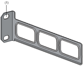
Figure 3-1 shows the appearance of a front mounting ear.
Figure 3-1 Appearance of a standard front mounting ear
|
(1) Screw hole used to fix the mounting ear to the cabinet (Use one M6 screw) |
|
(2) Screw hole used to fix the switch to the mounting ear |
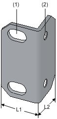
Figure 3-2 shows the appearance of a rear mounting ear.
Figure 3-2 Appearance of a rear mounting ear
|
(1) Screw hole used to fix the mounting ear to the cabinet (Use one M6 screw) |
When you install S3100 Series Ethernet Switches into 19-inch standard cabinets, you should select front mounting ears with a proper length (L1 as shown in Figure 3-1) according to the physical dimensions of switches. For the selection of front and rear mounting ears, see Table 3-3.
Table 3-3 Selection of mounting ear for S3100 Series Ethernet Switches
|
Model |
Physical dimensions (H × W × D) |
Configuration type of front mounting ear |
Configuration type of rear mounting ear |
|
S3100-26T-SI S3100-26C-SI S3100-26C-EPON-EI |
42 × 436 × 240 mm (1.65 × 17.2 × 9.4 in.) |
Standard |
— |
|
S3100-16T-SI S3100-16C-SI S3100-16C-EPON-EI |
42 × 436 × 200 mm (1.65 × 17.2 × 7.9 in.) |
Standard |
|
|
S3100-8T-SI S3100-8C-SI S3100-8C-EPON-EI |
42 × 326 × 200 mm (1.65 × 12.8 × 7.9 in.) |
Optional |
|
|
S3100-52TP-SI |
43.6 × 440 × 230 mm (1.7 × 17.3 × 9.1 in.) |
Standard |
— |
|
S3100-26TP-SI S3100-26TP-EI |
43.6 × 440 × 160 mm (1.7 × 17.3 × 6.3 in.) |
Standard |
|
|
S3100-16TP-SI S3100-16TP-EI |
43.6 × 360 × 160 mm (1.7 × 14.2 × 6.3 in.) |
Optional |
|
|
S3100-8TP-SI S3100-8TP-EI |
43.6 × 230 × 160 mm (1.7 × 9.1 × 6.3 in.) |
Optional |
|
|
S3100-26TP-PWR-EI |
43.6 × 440 × 420 mm (1.7 × 17.3 × 16.5 in.) |
Standard |
Standard |
|
S3100-16TP-PWR-EI |
43.6 × 300 × 260 mm (1.7 × 11.8 × 10.2 in.) |
Optional |
— |
|
S3100-8TP-PWR-EI |
43.6 × 300 × 220 mm (1.7 × 11.8 × 8.7 in.) |
Optional |
— |
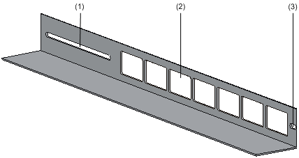
Introduction to guide rail
Figure 3-3 shows the appearance of a guide rail.
Figure 3-3 Appearance of a guide rail
|
(1) Slotted hole 1: Used to fix the guide rail to the rear bracket. You can adjust the screw hole position according to the position of the switch. |
|
(2) Cooling hole: Used for heat dissipation between switch and cabinet |
|
(3) Slotted hole 2: Used to fix the guide rail to the front bracket |
![]()
Guide rails purchased from H3C apply only to standard cabinets 1,000 mm (39.4 in.) deep. Use other supports to substitute for guide rails in the case of other cabinet depths.
Use front mounting ears to install a switch
Follow these steps to mount a switch into a 19-inch standard cabinet:
1) Wear an ESD-preventive wrist strap to check the grounding and stability of the cabinet.
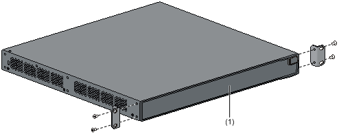
2) Take out the screws which are packed together with the front mounting ears, and fix one end of mounting ears to the switch, as shown in Figure 3-4.
Figure 3-4 Fix front mounting ears (1)
|
(1) Front panel |
3) Place the switch horizontally in a proper position, and fix the other end of mounting ears to the front brackets with screws and captive nuts, as shown in Figure 3-5.
Figure 3-5 Fix front mounting ears (2)
|
(1) Front square-holed bracket |
(2) Front panel |
|
(3) Front mounting ear |
|
Use front mounting ears and a tray to install a switch
Follow these steps to install a switch into a 19-inch standard cabinet:
1) Wear an ESD-preventive wrist strap to check the grounding and stability of the cabinet.
2) Fix the delivered tray horizontally in a proper position.
3) Take out the screws which are packed together with the front mounting ears, and fix one end of the front mounting ears to the switch, as shown in Figure 3-4.
4) Place the switch on the tray horizontally, slide the tray into the cabinet, and fix the other end of mounting ears to the front brackets with crews and captive nuts, as shown in Figure 3-5.
Use front and rear mounting ears to install a switch
Follow these steps to install a switch into a 19-inch standard cabinet:
1) Wear an ESD-preventive wrist strap to check the grounding and stability of the cabinet.
2) Take out the screws which are packed together with the front mounting ears, and fix one end of the front mounting ears to the switch, as shown in Figure 3-4.
3) Take out the load-bearing screws (packed together with the rear mounting ears) and place them in a proper position on the sides of the switch, as shown in Figure 3-6.
Figure 3-6 Fix front mounting ears and load-bearing screws
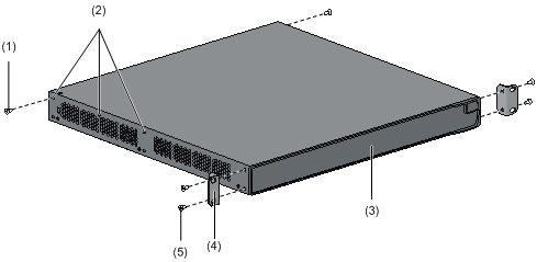
|
(1) Load-bearing screw |
(2) Optional positions for Load-bearing screw |
|
(3) Front panel |
(4) Front mounting ear |
|
(5) Screw used to fix front mounting ears to the switch |
|
![]()
There are three positions to mount a load-bearing screw on both sides of a switch. You should select a proper position according to the actual requirements. The rear mounting ears tightly contacted with the load-bearing screws can support the switch.
4) Select a position to install the switch and fix the rear mounting ears to the rear brackets with screws and captive nuts, as shown in Figure 3-7.
Figure 3-7 Fix rear mounting ears
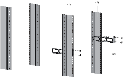
|
(1) Rear square-holed bracket |
(2) Rear mounting ear |
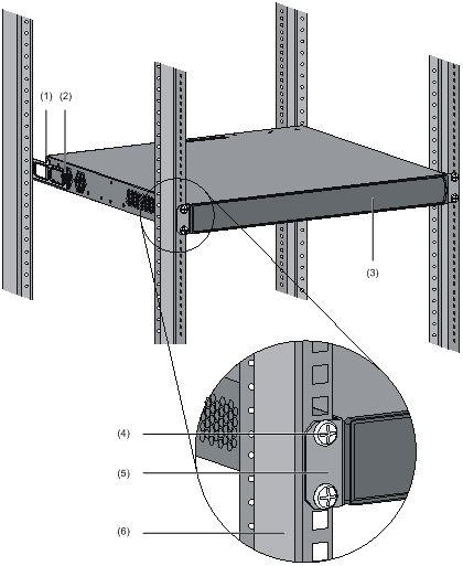
5) Hold the bottom of the switch with one hand and the front part of the switch with the other hand, and push the switch into the cabinet gently, as shown in Figure 3-8.
Figure 3-8 Fix front and rear mounting ears
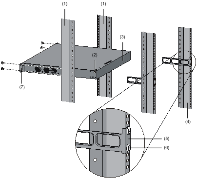
|
(1) Front square-holed bracket |
(2) Load-bearing screw: Used to bear the weight |
|
(3) Rear panel |
(4) Rear square-holed bracket |
|
(5) Rear mounting ear |
(6) Screw used to fix rear mounting ears to rear brackets |
|
(7) Front mounting ear |
|
After the switch is pushed into the cabinet, ensure that the upper edge of rear mounting ears is tightly contacted with the load-bearing screw, as shown in Figure 3-9.
Figure 3-9 Effect diagram of front and rear mounting ear installation (1)
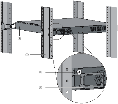
|
(1) Rear panel |
(2) Rear square-holed bracket |
|
(3) Load-bearing screw |
(4) Rear mounting ear |
6) Fix the other end of the front mounting ears to the front brackets with screws and captive nuts and ensure that front and rear mounting ears have fixed the switch in the cabinet securely, as shown in Figure 3-10.
Figure 3-10 Effect diagram of front and rear mounting ear installation (2)
|
(1) Load-bearing screw |
(2) Rear mounting ear |
|
(3) Front panel |
(4) Screw used to fix front mounting ears to front brackets |
|
(5) Front mounting ear |
(6) Front square-holed bracket |
Use front mounting ears and guide rails to install a switch
Follow these steps to install a switch into a 19-inch standard cabinet:
1) Wear an ESD-preventive wrist strap to check the grounding and stability of the cabinet.
2) Take out the screws packed together with the front mounting ears and fix one end of the front mounting ears to the switch, as shown in Figure 3-4.
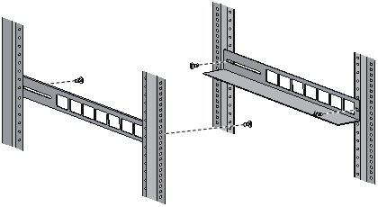
3) Install guide rails on the brackets on both sides of the cabinet with M5 self-tapping screws. Figure 3-11 is for reference only.
Figure 3-11 Install guide rails
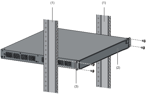
4) Hold the two sides of the switch and slide it gently along the guide rails into the cabinet until it is located in a proper position, as shown in Figure 3-12. Ensure that the bottom side of the guide rails and the switch are in close contact.
Figure 3-12 Install front mounting ears and guide rails
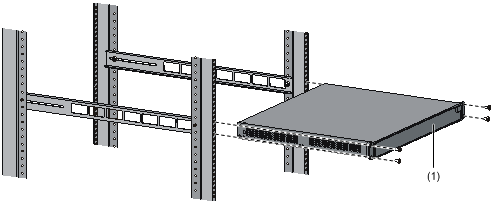
|
(1) Front panel |
5) Fix the other end of front mounting ears to the front brackets of the cabinet with M6 screws and captive nuts and ensure that the front mounting ears and guide rails have fixed the switch in the cabinet securely, as shown in Figure 3-13.
Figure 3-13 Effect diagram of front mounting ear and guide rail installation
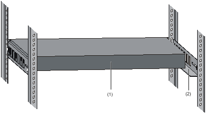
|
(1) Rear panel |
(2) Guide rail |
![]()
l No guide rails are delivered with the device.
l Ensure a clearance of 1U (44.45 mm, namely, 1.75 inches) between devices for the purpose of heat dissipation.
Desk Mounting
When a 19-inch standard cabinet is not available, you can simply place the switch on a clean desk. When doing so, you should ensure that:
l The desk is stable and well grounded.
l A clearance about 10 cm (3.9 in.) is reserved around the switch for heat dissipation.
l No heavy object is placed on the switch.
l S3100-SI and S3100-TP-EI Series Ethernet Switches are designed with no fan. Therefore, you should install them in a drafty environment, and keep at least a vertical distance of 1.5 cm (0.6 in.) between devices if you need to stack switches one upon another.
Wall Mounting
You can mount some models of S3100 Series Ethernet Switches on concrete walls or wood walls. Table 3-4 lists the models that support wall mounting.
Table 3-4 Models supporting wall mounting
|
Subseries |
Models supporting wall mounting |
Hole distance (mm) |
|
S3100-SI Ethernet switches |
S3100-8T-SI |
169 mm (6.65 in.) |
|
S3100-8C-SI |
||
|
S3100-EI Ethernet switches |
S3100-8TP-PWR-EI |
170 mm (6.69 in.) |
|
S3100-16TP-PWR-EI |
Introduction to screw and anchor kit
Figure 3-14 and Figure 3-15 show the recommended sizes (in mm) of screws and anchor kits used for mounting:
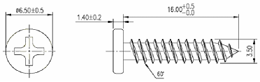
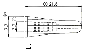
|
(1) Outside edge of anchor kit |
Installation procedure
The wall-mounting procedure is as follows:
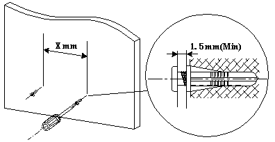
1) As shown in Figure 3-16, drill two holes 5 mm across in the wall on the same horizontal line, with a distance of X mm.
![]()
l The distance X between holes varies with devices. For specific distances, see Table 3-4.
l Drill two holes according to the sizes of anchor kits and screws so that anchor kits could go into the holes, only the edges could remain outside the wall, and the screws could be fixed on the wall tightly.
2) Insert anchor kits into the holes and keep only the edges outside the wall.
3) Drive screws into the anchor kits, keeping the inside of screw head at least 1.5 mm (0.06 in.) away from the edge of the anchor kit so that the switch could hang on the screws securely.
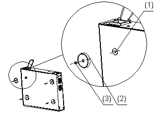
4) Align the two installation holes at the bottom of the switch with these two screws to hang the switch.
![]()
When mounting the switch, keep the Ethernet ports of the switch facing downwards and the two sides with ventilation holes vertical to the ground.
Magnet Mounting
The following two models support magnet mounting:
l S3100-8TP-PWR-EI
l S3100-16TP-PWR-EI
Introduction to magnetic mounting accessories
A set of magnetic mounting accessories consists of one permanent magnets and one M3*6 countersunk head screws, as shown in Figure 3-17. Four sets of magnetic mounting accessories are needed for each S3100 switch.
Figure 3-17 Magnet and countersunk head screw

|
(1) Permanent magnet |
(2) M3*6 countersunk head screw |
Installation procedure
Follow these steps to complete magnet mounting:
1) As shown in Figure 3-18, use a Phillips screwdriver to pass the countersunk head screw through the round hole at the center of the permanent magnet, fasten it to a blind nut in the dent of the switch bottom, and ensure that the permanent magnet and the switch are fastened reliably.
![]()
l Remove the cushion, if any, from the dent before installation.
l To ensure the firmness of installation, be sure to use four permanent magnets to secure each S3100 switch.
2) Attach the magnet-mounted device to the specified location. Take care not to get your fingers stuck between because the magnetism is very huge.
|
(1) Blind nut in the dent of the switch bottom |
(2) Permanent magnet |
|
(3) M3*6 countersunk head screw |
|
![]()
l Apply magnet mounting to only the above two models. Otherwise, a falloff or mis-operation may occur.
l Select the installation location carefully. In the case of poor surface, magnet mounting may not be reliable.
l Put the device at a stable place free from vibrations or shocks. Otherwise, personal injuries or equipment damage may occur.
l Avoid installing the device at a high place because personal injuries or equipment damage may occur in case of a falloff.
l Avoid frequently moving the desk-mounted device because such movements may damage the surface coating.
l Keep the front panel of the device facing downwards and the two sides with ventilation holes vertical to the ground, if you want to install the device vertically.
l Pay attention that the weight of external cables should not bring about a falloff, which may result in personal injuries or equipment damage.
l Keep floppy disks and magnetic cards away from magnets to avoid erasure of any information.
l Keep computers and monitors that are easily influenced by magnetic fields away from magnets. Otherwise, faults may occur to these electronic devices.
Connecting Grounding Cable
![]()
l Correctly connecting the switch ground wire is crucial to the lightning protection and electromagnetic susceptibility (EMS) of a switch.
l The power and grounding terminals in this section are for illustration only.
When a Grounding Strip is Available
When a grounding strip is available at the installation site, attach one end of the yellow-green ground wire of the switch to the grounding screw on the grounding strip (the grounding screw and the grounding hole are on the rear panel of the switch and are marked with a grounding sign). To do this, follow these steps:
Step 1: Remove the grounding screw from the rear panel of the switch chassis.
Step 2: Put the supplied OT terminal of the PGND cable on the grounding screw.
Step 3: Fasten the grounding screw, which is attached with the OT terminal of the PGND cable, into the grounding screw hole with a screwdriver.
Figure 3-19 Connect the PGND cable to the grounding hole of switch
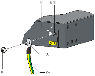
|
(2) Grounding sign |
|
|
(3) Grounding hole |
(4) OT terminal |
|
(5) PGND cable |
(6) Grounding screw |
To attach the other end of the PGND cable to the grounding strip in the equipment room, follow these steps:
Step 1: Cut the PGND cable to a proper length according to the distance between the switch and the grounding strip.
Step 2: Peel 5 mm (0.20 in.) of insulation sheath using a wire stripper, and then insert the naked metal part through the black insulation covering into the end of the OT terminal. (Two OT terminals are provided with the PGND cable when shipped with the switch; select a proper OT terminal according to the size of the grounding post.)
Step 3: Secure the metal part of the cable to the OT terminal with a crimper, and then cover it with the insulation covering. Then heat the insulation covering with a blowing machine to let it completely cover the metal part.
Step 4: Connect the OT terminal to the grounding pole of the grounding strip, and then fasten it with a hex nut.
Figure 3-20 Connect the ground wire to the grounding strip
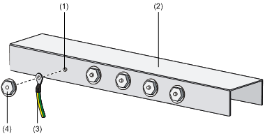
|
(1) Grounding post |
(2) Grounding strip |
|
(3) PGND cable |
(4) Hex nut |
![]()
The fire main and lightning rod of a building are not suitable for grounding the switch. The ground wire of the switch should be connected to the grounding device for the equipment room.
Where a Grounding Conductor Can be Buried
When there is no grounding strip, but an area with exposed earth is available nearby where a grounding conductor can be buried, hammer a 0.5 m (1.64 ft.) or longer angle iron or steel tube into the earth. The angle iron should have a dimension no less than 50 × 50 × 5 mm (1.97 × 1.97 × 0.20 in.) and the steel tube should have a wall thickness no less than 3.5 mm (0.14 in.) and be zinc-coated. Weld the yellow-green ground wire to the angel iron or steel tube and treat the joint for corrosion protection.
Figure 3-21 Ground the switch by burying the grounding conductor into the earth
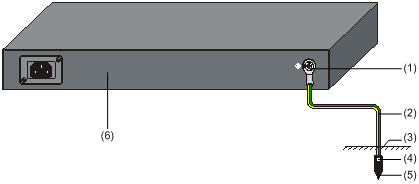
|
(2) PGND cable |
|
|
(3) Earth |
(4) Joint |
|
(5) Grounding conductor |
(6) Switch rear panel |
In Other Installation Sites
When the switch is AC-powered
For an AC-powered switch, if neither of the above-mentioned two conditions is available, ground the switch through the PE wire of the AC power supply. Make sure the PE wire is well connected to the ground at the power distribution room or AC transformer side, the switch PE terminal and the PE wire are well connected, and the three-wire input cable of the PGND cable is used for the power supply cable. If the PE wire of the AC power supply is not grounded at the power distribution room or AC transformer side, report the problem and make reconstructions.
Figure 3-22 Ground through an AC power PE wire
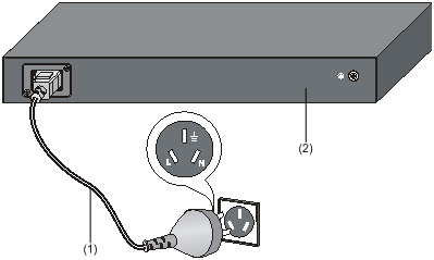
|
(1) Three-wire AC power input cable |
(2) Switch rear panel |
When the Switch is DC-powered
For a DC-powered switch, if neither of the first two conditions mentioned above is available, ground the switch through the return wire (RTN) of the DC power supply. In this case, make sure this RTN wire is well connected to the ground at the DC output of the DC power cabinet.
Figure 3-23 Ground through the PGND of a power cabinet
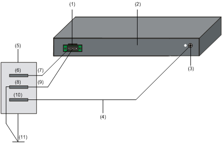
|
(2) Switch rear panel |
(3) Grounding screw |
|
|
(4) PGND cable |
(5) AC/DC power cabinet |
(6) –48V strip |
|
(7) –48V |
(8) RTN strip |
(9) RTN |
|
(10) PGND strip |
(11) Grounding |
|
Connection of Power Cable
Connecting AC Power Cable
AC power socket (recommended)
You are recommended to use a mono-phase three-core power socket with a neutral point or a multi-function power socket for computers. The neutral point of the power in your building must be well grounded. Normally, the neutral point of the power supply system in your building has already been grounded during the construction and wiring; but you should make sure this is the fact.
Figure 3-24 Recommended AC power socket
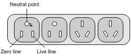
Connecting AC power cable
1) Connect one end of the grounding cable (delivered with the switch) to the grounding screw on the rear of the chassis and the other end to the ground nearby.
2) Connect one end of the power cable to the power socket on the rear panel of the chassis and the other end to an outside AC power socket.
3) Install the power cord retainer for the AC power cord on S3100-TP-PWR-EI series Ethernet Switches. Insert the two ends of the power cord retainer into the slots at both sides of the AC power input, and then set the power cord into the notch of the power cord retainer, as shown in Figure 3-25.
Figure 3-25 Install the power cord retainer
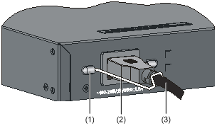
|
(1) Power cord retainer holder |
(2) Power cord retainer |
(3) Power cord |
![]()
l Currently, only the S3100-TP-PWR-EI series Ethernet Switches are equipped with an AC power cord retainer to prevent the power cord from accidentally falling off.
l The location of the power cord retainer holder varies with S3100-TP-PWR-EI series Ethernet Switches.
4) Check whether the PWR LED on the front panel of the switch is ON. If yes, the power is properly connected.
![]()
Before powering on the switch, you should properly connect the grounding cable.
Connecting DC Power Cable
DC power cable connection for S3100-C-SI/S3100-TP-EI DC-powered Ethernet switch
Figure 3-26 DC input terminal block of S3100-C-SI/S3100-TP-EI DC-powered Ethernet switch
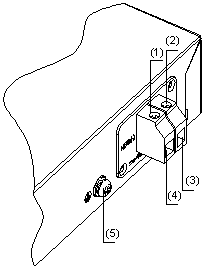
|
(1) Screw 1 |
(2) Screw 2 |
|
(3) RTN (+) terminal |
(4) NEG(-) terminal (–48 V to –60 V) |
|
(5) Grounding screw |
|
![]()
The location of the DC input terminal block varies with devices.
1) Connect one end of the grounding cable (delivered with the switch) to the grounding screw and the other end to the ground nearby.
2) Use a flat-blade screwdriver to loosen the two screws on the DC input terminal blocks. Connect the power ground return cable to the RTN(+) terminal and the power output cable to the NEG(-) terminal. Tighten the two screws respectively to fix the power cables.
3) Check whether the PWR LED on the front panel of the switch is ON. If yes, the power is properly connected.
![]()
l Before powering on the switch, you should properly connect the grounding cable.
l The DC power cable should be less than 3 meters long.
DC power cable connection for S3100-26TP-PWR-EI Ethernet switch
Figure 3-27 RPS DC power socket for S3100-26TP-PWR-EI Ethernet switch
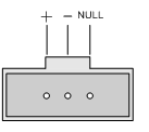
|
+: Working ground |
–: Voltage input (–52 VDC to –56 VDC) |
NULL: Reserved |
1) Connect one end of the grounding cable (delivered with the switch) to the grounding screw and the other end to the ground nearby.
2) Assemble the DC power connector as follows:
Figure 3-28 RPS DC power connector
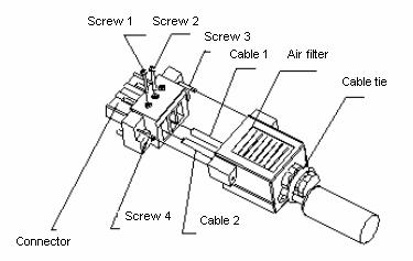
l As shown in Figure 3-28, pass the two power cables through the air filter, insert them into the corresponding holes, and tighten them with screw 1 and screw 2. The positive and negative poles of the power cables must correspond to the silkscreen above the holes.
l Use a flat-blade screwdriver to fix the air filter on the connector with screw 3 and screw 4, as shown in Figure 3-28.
l Use cable ties to bind the two power cables to the protruding part at the back of the air filter, as shown in Figure 3-28.
3) Insert the connector into the DC socket directly. Use the flat-blade screwdriver to fix the connector with screw 1 and screw 2 (delivered with the switch), as shown in Figure 3-29.
Figure 3-29 Fix the RPS DC power connector to the chassis
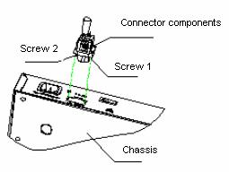
![]()
The location of the DC power socket varies with devices.
4) Connect the other end of the RPS DC power cord to the external RPS power supply system.
5) Check whether the PWR LED on the front panel of the switch is ON. If yes, the power is properly connected.
![]()
l Before powering on the switch, you must properly connect the grounding cable.
l The DC power cable should be less than 3 meters long.
l Only the recommended RPS can be used for S3100-26TP-PWR-EI Ethernet switches. The –48 VDC in the equipment room cannot be used directly. Otherwise, the device may be damaged.
Installing an Expansion Interface Module
Installation procedure
Step 1: Wear an ESD-preventive wrist strap, ensure a good skin contact and make sure that the ESD-preventive wrist strap is properly grounded.
Step 2: Loosen the mounting screws of the filler panel on the interface module slot of the switch's front panel with a Phillips screwdriver and remove the filler panel.
![]()
Keep the removed filler panel properly for future use.
Step 3: Unwrap the interface module. Gently push the interface module in along the slot guide rails until the interface module is in close contact with the switch.
Step 4: Tighten the captive screws with a Phillips screwdriver to fix the interface module.
Removal procedure
Step 1: Wear an ESD-preventive wrist strap, ensure a good skin contact and make sure that the ESD-preventive wrist strap is properly grounded.
Step 2: Use a Phillips screwdriver to loosen the captive screws at both sides of the interface module until all spring pressure is released.
Step 3: Pull the interface module along the guide rails until it completely comes out of the switch chassis.
![]()
When installing or removing an optional interface module, pay attention to the following points:
l Do not touch the surface-mounted components directly with your hands.
l Do not use too much force in the operation.
l After removing an interface module, if no new module is to be installed, install the filler panel as soon as possible to prevent dust and ensure the normal ventilation in the switch.
Connecting Optical Fiber
![]()
l After a switch starts, the optical port may emit invisible radial when there is no optical connector connected to it and the protective cap is removed from it. Therefore, do not stare into the optical interface.
l Be sure to cover the protective cap within 10 seconds if an optical connector is not in use to keep the optical connector clean.
l Be sure to cover the protective cap if an optical port has no optical connector attached.
l Place the protective caps in a safe place when an optical port has fiber connected to prepare for the cases the fiber is pulled out.
![]()
The following section describes the procedures to connect optical fiber to an ONU card. The procedures also apply to other subcards.
Step 1: Remove the protective cap from the optical connector of the fiber.
Step 2: Remove the protective cap from the PON interface of the ONU subcard.
Step 3: Plug the optical connector into the PON interface of the ONU subcard.
Installation Verification
After completing the installation, check that:
l The correct power is used.
l The grounding cable is connected.
l The power cable is properly connected.
l All the interface cables are cabled indoors. If there is any cable wired outdoors, verify that socket strip with lightning protection and lightning arresters for network ports have been properly connected.
Establishing Configuration Environment
Set up the configuration environment as follows:
Connect a terminal (a PC in this example) to the console port on the switch with a console cable.
Figure 4-1 Network diagram for configuration environment setup
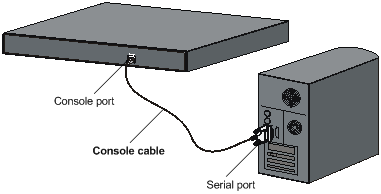
Connecting the Console Cable
Console Cable
The console cable is an 8-core shielded cable. At one end of the cable is a crimped RJ-45 connector to be connected to the console port of the switch; at the other end of the cable is a DB-9 (female) connector to be connected to the 9-core (pin) serial port on the Console terminal. See the following figure.
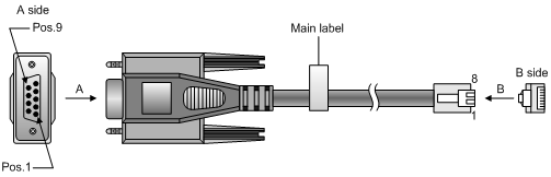
Table 4-1 Console cable connector pinouts and mapping relation
|
RJ-45 |
Signal |
Direction |
DB-9 |
|
1 |
RTS |
← |
7 |
|
2 |
DTR |
← |
4 |
|
3 |
TXD |
← |
3 |
|
4 |
CD |
→ |
1 |
|
5 |
GND |
— |
5 |
|
6 |
RXD |
→ |
2 |
|
7 |
DSR |
→ |
6 |
|
8 |
CTS |
→ |
8 |
Connection Procedure
Follow these steps to connect a terminal device, a PC for example, to the switch:
Step 1: Connect the DB-9 female connector of the console cable to the serial port of the PC or the terminal device used to configure the switch.
Step 2: Connect the RJ-45 connector of the console cable to the console port of the switch.
Identify the label of the port before connecting a connector.
![]()
When connecting a PC to a powered-on switch, you are recommended to connect the DB-9 connector of the console cable to the PC before connecting the RJ-45 connector to the switch. When disconnecting a PC from a powered-on switch, you are recommended to disconnect the DB-9 connector of the console cable from the PC after disconnecting the RJ-45 connector from the switch.
Setting Terminal Parameters
Step 1: Start the PC and run the terminal emulation program such as the Terminal of Windows 3.1 or the HyperTerminal of Windows 95/98/NT/2000/XP.
Step 2: Set terminal parameters (take the HyperTerminal of Windows 2000 as an example).
Parameter requirements: Set bits per second to 9600, data bits to 8, parity check to none, stop bits to 1 and flow control to none. Select VT100 as terminal emulation. The following is the specific procedure:
1)
Select [Start/Program/Accessories/Communications/HyperTerminal]
to enter the HyperTerminal window, where click the  icon to establish a new connection.
The system displays the Connection Description interface, as shown in the
following figure.
icon to establish a new connection.
The system displays the Connection Description interface, as shown in the
following figure.
Figure 4-3 Connection description interface of HyperTerminal
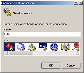
2) Type in the name of the new connection in the connection description interface and click <OK>. The system pops up the following interface. Select the serial port to be used from [Connect using].
Figure 4-4 Setting the serial port used by the HyperTerminal connection
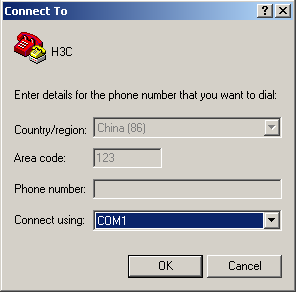
3) Click <OK> after selecting a serial port and the system pops up the following interface. In the interface, set the bits per second to 9600, data bits to 8, parity check to none, stop bits to 1, and flow control to none.
Figure 4-5 Setting serial port parameters
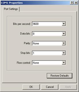
4) Click <OK> after setting the serial port parameters, and the system enters the following interface.
Choose [Properties] in the HyperTerminal dialog box to enter the properties window. Click [Settings] to enter the following properties setting window, and select VT100 as the terminal emulation. Click <OK> when the selection is done.
Figure 4-7 Set terminal emulation in H3C Properties window
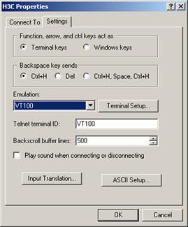
Booting Switch
Checking Before Powering on the Switch
Before powering on the switch, verify that:
l The power cable and grounding cable are properly connected.
l The supply voltage is consistent with that required by the switch.
l The console cable is properly connected; the terminal (which can be a PC) used for configuration has been started; and the configuration parameters have been set.
Powering on the Switch
All the S3100 series Ethernet switches have the same Boot ROM display style. This document takes the Boot ROM display of the S3100-16C-SI switch as example:
Starting......
***********************************************************
* *
* H3C S3100-16C-SI BOOTROM, Version 506 *
* *
***********************************************************
Copyright(c) 2004-2007 Hangzhou H3C Technologies Co., Ltd.
Creation date : Apr 15 2007, 10:12:36
CPU Clock Speed : 200MHz
BUS Clock Speed : 33MHz
Memory Size : 64MB
Mac Address : 000fe20f3100
Press Ctrl-B to enter Boot Menu... 2
The last line prompts you to enter the Boot Menu and waits two seconds for your response.
![]()
l The system has two startup modes: normal and fast. The normal startup mode spends a little more time than the fast startup mode because the former takes more self-test operations.
l By default, the system starts up in fast mode and the waiting time here is two seconds. While, if you set the startup mode to normal, this waiting time is five seconds. For the setting of the startup mode, refer to the next section.
l If you press <Ctrl+B> within 2 seconds, the Boot Menu is displayed:
BOOT MENU
1. Download application file to flash
2. Select application file to boot
3. Display all files in flash
4. Delete file from flash
5. Modify bootrom password
6. Enter bootrom upgrade menu
7. Skip current configuration file
8. Set bootrom password recovery
9. Set switch startup mode
0. Reboot
Enter your choice(0-9):
l If you perform no operation or press a key other than <Ctrl+B> within two seconds, once the waiting time becomes zero, the system begins to automatically start up and the following information is displayed:
Auto-booting...
Decompress Image...................................................
...................................................................
...................................................................
...................................................................
...................................................................
...............................................OK!
Starting at 0x80100000...
User interface aux0 is available.
Press ENTER to get started.
Changing the Startup Mode
By default, the system starts up in fast mode. If you want to change the startup mode to normal, press <Ctrl+B> within two seconds to enter the Boot Menu showed below:
BOOT MENU
1. Download application file to flash
2. Select application file to boot
3. Display all files in flash
4. Delete file from flash
5. Modify bootrom password
6. Enter bootrom upgrade menu
7. Skip current configuration file
8. Set bootrom password recovery
9. Set switch startup mode
0. Reboot
Enter your choice(0-9):
Enter 9, and the system prompts you to change the startup mode:
The current mode is fast startup mode!
Are you sure to change it to full startup mode? Yes or No(Y/N)
Enter Y, and the system gives the following prompts:
Setting startup mode...done!
BOOT MENU
1. Download application file to flash
2. Select application file to boot
3. Display all files in flash
4. Delete file from flash
5. Modify bootrom password
6. Enter bootrom upgrade menu
7. Skip current configuration file
8. Set bootrom password recovery
9. Set switch startup mode
0. Reboot
Enter your choice(0-9):
Enter 0, the system reboots in normal mode and displays the following information:
Starting......
***********************************************************
* *
* H3C S3100-16C-SI BOOTROM, Version 506 *
* *
***********************************************************
Copyright(c) 2004-2007 Hangzhou H3C Technologies Co., Ltd.
Creation date : Apr 15 2007, 10:12:36
CPU Clock Speed : 200MHz
BUS Clock Speed : 33MHz
Memory Size : 64MB
Mac Address : 000fe20f3100
Press Ctrl-B to enter Boot Menu... 5
In normal startup mode, the waiting time here is five seconds. If you press <Ctrl+B> within five seconds, the Boot Menu is displayed. If you perform no operation or press a key other than <Ctrl+B> within five seconds, the system begins to automatically start up and the following information is displayed:
Auto-booting...
Decompress Image...................................................
...................................................................
...................................................................
...................................................................
...................................................................
...............................................OK!
Starting at 0x80100000...
Initialize LS41LTSGB0......................OK!
SDRAM fast selftest........................OK!
Flash fast selftest........................OK!
Switch chip selftest.......................OK!
Slot 1/1/1 has no module
PHY selftest...............................OK!
Please check port leds...............FINISHED!
User interface aux0 is available.
Press ENTER to get started.
The appearance of "Press ENTER to get started" indicates that the switch finishes the auto-startup.
Press <Enter>, and the following prompt is displayed:
<H3C>
You can configure the switch now.
![]()
The H3C S3100 Series Switches provides abundant command views. For detailed descriptions about the configuration commands and CLI, refer to H3C S3100 Series Ethernet Switches Operation Manual and H3C S3100 Series Ethernet Switches Command Manual.
Traditionally, the loading of switch software is accomplished through the serial port. This approach is slow, inconvenient, and cannot be used for remote real-time loading. To resolve these problems, the TFTP and FTP modules are introduced into the switch. With these modules, the software and files can be loaded through Ethernet port conveniently.
This chapter introduces how to load Boot ROM and host software into a switch locally and how to do this remotely.
Introduction to Loading Approaches
You can load the software locally by using:
l XModem via console port
l TFTP via Ethernet port
l FTP via Ethernet port
You can load the software remotely by using:
l FTP
l TFTP
![]()
Boot ROM software version should be compatible with the host software version when you load the Boot ROM and host software.
Local Software Loading
If your terminal is directly connected to the switch, you can load Boot ROM and host software locally.
Before loading the software, make sure that your terminal is correctly connected to the switch to ensure the successful loading.
![]()
The loading process of the Boot ROM software is the same as that of the host software, except that during the Boot ROM loading process, you should press <Ctrl+U> and <Enter> after entering the Boot Menu and the system gives somewhat different prompts. The following text mainly describes the Boot ROM loading process.
Boot Menu
Take S3100-16C-SI switch as example. After the switch is powered on, the system displays:
Starting......
***********************************************************
* *
* H3C S3100-16C-SI BOOTROM, Version 506 *
* *
***********************************************************
Copyright(c) 2004-2007 Hangzhou H3C Technologies Co., Ltd.
Creation date : Apr 15 2007, 10:12:36
CPU Clock Speed : 200MHz
BUS Clock Speed : 33MHz
Memory Size : 64MB
Mac Address : 000fe20f3100
Press Ctrl-B to enter Boot Menu... 5
Press <Ctrl+B>. The system displays:
Password :
![]()
To enter the Boot Menu, you should press <Ctrl+B> within five seconds after the information “Press Ctrl-B to enter Boot Menu...” appears. Otherwise, the system starts to decompress the program; and if you want to enter the Boot Menu at this time, you will have to restart the switch.
Input the correct Boot ROM password (by default, no password is set on the switch). The system enters the Boot Menu:
BOOT MENU
1. Download application file to flash
2. Select application file to boot
3. Display all files in flash
4. Delete file from flash
5. Modify bootrom password
6. Enter bootrom upgrade menu
7. Skip current configuration file
8. Set bootrom password recovery
9. Set switch startup mode
0. Reboot
Enter your choice(0-9):
Loading Software Using XModem Through Console Port
Introduction to XModem
XModem is a file transfer protocol that is widely used due to its simplicity and good performance. XModem transfers files via console port. It supports two types of data packets (128 bytes and 1 KB), two check methods (checksum and CRC), and error packet retransmission mechanism (generally the maximum number of retransmission attempts is ten).
The XModem transmission procedure is completed by the cooperation of a receiving program and a sending program: The receiving program sends a negotiation packet to negotiate a packet check method. After the negotiation, the sending program starts to transmit data packets. When receiving a complete packet, the receiving program checks the packet using the agreed method. If the check succeeds, the receiving program sends an acknowledgement packet and the sending program proceeds to send another packet; otherwise, the receiving program sends a negative acknowledgement packet and the sending program retransmits the packet.
Loading Boot ROM software
Follow these steps to load the Boot ROM software:
Step 1: At the prompt "Enter your choice (0-9):" in the Boot Menu, press <6> or <Ctrl+U>, and then press <Enter> to enter the Boot ROM update menu shown below:
Bootrom update menu:
1. Set TFTP protocol parameter
2. Set FTP protocol parameter
3. Set XMODEM protocol parameter
0. Return to boot menu
Enter your choice(0-3):
Step 2: Enter 3 in the above menu to load the Boot ROM software using XModem. The system displays the following download bits per second setting menu:
Please select your download baudrate:
1.* 9600
2. 19200
3. 38400
4. 57600
5. 115200
0. Return
Enter your choice (0-5):
Step 3: Choose an appropriate download bits per second. For example, if you select 5, the 115200 bps rate is chosen, and the system displays the following information:
Download baudrate is 115200 bps
Please change the terminal's baudrate to 115200 bps and select XMODEM protocol
Press enter key when ready
Now, press <Enter>.
![]()
If you have chosen 9600 bps, you do not need to modify the HyperTerminal’s bits per second, and therefore you can skip Step 4 and 5 below and proceed to Step 6 directly. In this case, the system will not display the above information.
Step 4: Select [File/Properties] in the HyperTerminal window, click <Configuration> in the popup dialog box, and select the bits per second of 115200 bps in the appeared console port configuration dialog box.
Figure 5-1 Properties dialog box
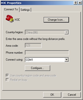
Figure 5-2 Console port configuration dialog box
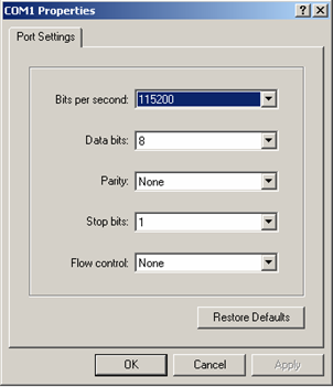
Step 5: Click the <Disconnect> button to disconnect the HyperTerminal from the switch and then click the <Call> button to reconnect the HyperTerminal to the switch.
Figure 5-3 Call and disconnect buttons
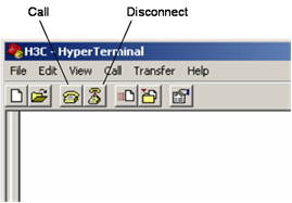
![]()
The new bits per second takes effect only after you disconnect and reconnect the terminal emulation program.
Step 6: Press <Enter> to start downloading the program. The system displays the following information:
Now please start transfer file with XMODEM protocol.
If you want to exit, Press <Ctrl+X>.
Loading ...CCCCCCCCCC
Step 7: Choose [Transfer/Send File] in the HyperTerminal window, and in the following popup dialog box click <Browse>, select the software you need to download, and set the protocol to XModem.
Figure 5-4 Send file dialog box
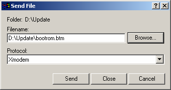
Step 8: Click <Send>. The system displays the following page.
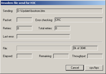
After the download completes, the system displays the following information:
Loading ...CCCCCCCCCC done!
![]()
You do not need to reset the HyperTerminal’s bits per second and can skip the last step if you have chosen 9600 bps. In this case, the system displays the prompt “BootROM is updating now.....................................done!” instead of the prompt "Your baudrate should be set to 9600 bps again! Press enter key when ready".
Step 9: Reset HyperTerminal’s bits per second to 9600 bps (refer to Step 4 and 5). Then, press any key as prompted. The system will display the following information when it completes the loading.
Bootrom is updating now.....................................done!
Loading host software
Follow these steps to load the host software:
Step 1: Select <1> in Boot Menu. The system displays the following information:
1. Set TFTP protocol parameter
2. Set FTP protocol parameter
3. Set XMODEM protocol parameter
0. Return to boot menu
Enter your choice(0-3):3
The subsequent steps are the same as those for loading the Boot ROM software, except that the system gives the prompt for host software loading instead of Boot ROM loading.
Loading Software Using TFTP Through Ethernet Port
Introduction to TFTP
TFTP, one protocol in TCP/IP protocol suite, is used for trivial file transfer between client and server. It uses UDP to provide unreliable data stream transfer service.
Loading Boot ROM software
Figure 5-6 Local loading using TFTP
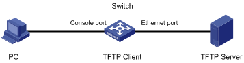
Step 1: As shown in Figure 5-6, connect the switch through an Ethernet port to the TFTP server, and connect the switch through the console port to the configuration PC.
![]()
You can use one PC as both configuration device and TFTP server.
Step 2: Run the TFTP server program on the TFTP server, and specify the path of the program to be loaded.
![]()
TFTP server program is not provided with the H3C Series Switches.
Step 3: Run the terminal emulation program on the configuration PC. Start the switch. Then enter the Boot Menu.
At the prompt "Enter your choice (0-9):" in the Boot Menu, press <6> or <Ctrl+U>, and then press <Enter> to enter the BootROM update menu shown below:
Bootrom update menu:
1. Set TFTP protocol parameter
2. Set FTP protocol parameter
3. Set XMODEM protocol parameter
0. Return to boot menu
Enter your choice(0-3):
Step 4: Enter 1 to download the Boot ROM software using TFTP. Then set the following TFTP-related parameters as required:
Load File name :S3100-SI.btm
Switch IP address :1.1.1.2
Server IP address :1.1.1.1
Step 5: Press <Enter>. The system displays the following information:
Are you sure to update your bootrom?Yes or No(Y/N)
Step 6: Enter Y to start file downloading or N to return to the BootROM update menu. If you enter Y, the system begins to download and update the Boot ROM software. Upon completion, the system displays the following information:
Loading........................................done
Bootrom updating..........done!
Loading host software
Follow these steps to load the host software of the switch.
Step 1: Select <1> in Boot Menu. The system displays the following information:
1. Set TFTP protocol parameter
2. Set FTP protocol parameter
3. Set XMODEM protocol parameter
0. Return to boot menu
Enter your choice(0-3):1
The subsequent steps are the same as those for loading the Boot ROM software, except that the system gives the prompt for host software loading instead of Boot ROM loading.
Loading Software Using FTP Through Ethernet Port
Introduction to FTP
FTP is an application-layer protocol in the TCP/IP protocol suite. It is used for transferring files between server and client. FTP runs over UDP to provide unreliable data transmission.
You can use FTP to load software to the switch through an Ethernet port. In this case, the switch can act as an FTP server or an FTP client. In the following example, the switch acts as an FTP client.
Loading Boot ROM software
Figure 5-7 Local loading using FTP
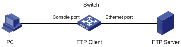
Step 1: As shown in Figure 5-7, connect the switch through an Ethernet port to the FTP server, and connect the switch through the console port to the configuration PC.
![]()
You can use one computer as both configuration device and FTP server.
Step 2: Run the FTP server program on the FTP server, configure an FTP user name and password, and specify the path of the program to be downloaded.
Step 3: Run the terminal emulation program on the configuration PC. Start the switch. Then enter the Boot Menu.
At the prompt "Enter your choice (0-9):" in the Boot Menu, press <6> or <Ctrl+U>, and then press <Enter> to enter the BootROM update menu shown below:
Bootrom update menu:
1. Set TFTP protocol parameter
2. Set FTP protocol parameter
3. Set XMODEM protocol parameter
0. Return to boot menu
Enter your choice(0-3):
Step 4: Enter 2 in the above menu to download the Boot ROM software using FTP. Then set the following FTP-related parameters as required:
Load File name :S3100-SI.btm
Switch IP address :10.1.1.2
Server IP address : 10.1.1.1
FTP User Name :3100-SI
FTP User Password :abc
Step 5: Press <Enter>. The system displays the following information:
Are you sure to update your bootrom?Yes or No(Y/N)
Step 6: Enter Y to start file downloading or N to return to the BootROM update menu. If you enter Y, the system begins to download and update the program. Upon completion, the system displays the following information:
Loading........................................done
Bootrom updating..........done!
Loading host software
Follow these steps to load the host software:
Step 1: Select <1> in Boot Menu. The system displays the following information:
1. Set TFTP protocol parameter
2. Set FTP protocol parameter
3. Set XMODEM protocol parameter
0. Return to boot menu
Enter your choice(0-3):2
The subsequent steps are the same as those for loading the Boot ROM software, except for that the system gives the prompt for host software loading instead of Boot ROM loading.
Remote Software Loading
If your terminal is indirectly connected to the switch through Internet, you can telnet to the switch, and use FTP or TFTP to load Boot ROM and host software remotely.
Remote Loading Using FTP
As shown in Figure 5-8, a PC is used as both configuration device and FTP server. You can telnet to the switch, and then execute the FTP commands to download the host program s3100-SI.bin and the Boot ROM program s3100-SI.btm from the remote FTP server (with IP address 202.10.10.53) to the switch.
Figure 5-8 Remote loading using FTP
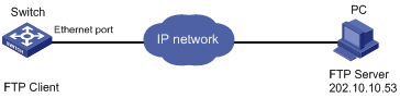
Step 1: Download the software to the switch using FTP commands.
<H3C> ftp 202.10.10.53
Trying ...
Press CTRL+K to abort
Connected.
220 WFTPD 2.0 service (by Texas Imperial Software) ready for new user
User(none):abc
331 Give me your password, please
Password:
230 Logged in successfully
[ftp] get s3100-SI.bin
[ftp] get s3100-SI.btm
[ftp] bye
Step 2: Update the Boot ROM program on the switch.
<H3C> boot bootrom s3100-SI.btm
please wait ...
Bootrom is updated!
Step 3: Update the host program on the switch.
<H3C> boot boot-loader s3100-SI.bin
<H3C> display boot-loader
Unit 1:
The current boot app is: s3100-SI.bin
The main boot app is: s3100-SI.bin
The backup boot app is:
Step 4: Restart the switch.
<H3C> reboot
![]()
Before restarting the switch, make sure other configurations are all saved to avoid the loss of configuration information.
After the above operations, the Boot ROM and host software loading is completed.
Pay attention to the following:
l Host software loading takes effect only after you restart the switch with the reboot command.
l If the space of the flash memory is not enough, you can delete the useless files in the flash memory before software downloading.
l No power-breaking is permitted during software loading.
Remote Loading Using TFTP
The remote loading by using TFTP is similar to the remote loading by using FTP. The only difference is that it is TFTP that you use when loading software to the switch. In this case, the switch can only be used as a TFTP client.
Software Loading Failure
If software loading fails, the system keeps running in original version.
In this case, check if the physical ports are properly connected:
l If not, reconnect them correctly and restart the loading procedure.
l If so, check the loading procedure information displayed on the HyperTerminal for input errors. If there is any input error, restart the loading procedure with correct input. For example:
1) When using XModem, verify that you have reset the bits per second of the HyperTerminal to 9600 bps after loading the software with a bits per second other than 9600 bps;
2) When using TFTP, verify that you have provided:
l Correct server and switch IP addresses,
l Correct name of the software to be loaded,
l Correct working path of TFTP server;
3) When using FTP, verify that you have provided:
l Correct server and switch IP addresses,
l Correct name of the software to be loaded,
l Correct username and password.
If software loading fails but there are neither physical connection problems nor input errors, please contact your agent for help.
Missing Password
Missing user password
If you forget your user password, you can:
Access the Boot Menu:
BOOT MENU
1. Download application file to flash
2. Select application file to boot
3. Display all files in flash
4. Delete file from flash
5. Modify bootrom password
6. Enter bootrom upgrade menu
7. Skip current configuration file
8. Set bootrom password recovery
9. Set switch startup mode
0. Reboot
Enter your choice(0-9):
Select <7> and restart the switch. After that, the system will skip the configuration file.
Missing Boot ROM Password
Please contact your agent.
Power System Failure
You can check whether the power system of the switch fails by viewing the POWER indicator on the front panel. If it is in normal operation, the POWER indicator should stay on. Otherwise, please check that:
l The switch power cable is correctly connected.
l The power input to the switch matches the requirement as labeled on the switch.
Configuration System Failure
After the switch is powered on and the system is normal, the booting information will be displayed on the configuration terminal. If the configuration system has any faults, there will not be any screen display at the configuration terminal or the displayed characters will be totally illegible.
Troubleshooting when there is no terminal display
If there is no output information after the configuration is powered on, please check that:
l The power supply is normal
l The console cable is properly connected
If no problems are found after the above-mentioned items have been checked, the cause may lie in the console cable or the settings of the terminal (such as HyperTerminal) parameters. Please perform the corresponding check.
Troubleshooting when the terminal display is illegible
If there is illegible display at the configuration terminal, the cause might lie in the parameter setting error at the terminal (such as HyperTerminal). Please confirm the following terminal parameter (such as HyperTerminal) settings:
l Bits per second: 9600
l Data bits: 8
l Parity: None
l Stop bits: 1
l Flow control: None
