- Table of Contents
-
- H3C S3100-52P Ethernet Switch Operation Manual-Release 1500(V1.02)
- 00-1Cover
- 00-2Overview
- 01-CLI Operation
- 02-Login Operation
- 03-Configuration File Management Operation
- 04-VLAN Operation
- 05-IP Address and Performance Confiugration Operation
- 06-GVRP Operation
- 07-Port Basic Configuration Operation
- 08-Link Aggregation Operation
- 09-Port Isolation Operation
- 10-DLDP Operation
- 11-MAC Address Table Operation
- 12-MSTP Operation
- 13-Multicast Operation
- 14-Routing Protocol Operation
- 15-802.1x Operation
- 16-AAA-RADIUS-HWTACACS Operation
- 17-Centralized MAC Address Authentication Operation
- 18-DHCP Operation
- 19-ARP Operation
- 20-ACL Operation
- 21-QoS Operation
- 22-Mirroring Operation
- 23-Cluster Operation
- 24-SNMP and RMON Operation
- 25-NTP Operation
- 26-SSH Terminal Service Operation
- 27-File System Management Operation
- 28-FTP and TFTP Operatio
- 29-Information Center Operation
- 30-System Maintenance and Debugging Operation
- 31-VLAN VPN Operation
- 32-HWPing Operation
- 33-DNS Operation
- 34-Appendix
- Related Documents
-
| Title | Size | Download |
|---|---|---|
| 23-Cluster Operation | 377.51 KB |
1.1.5 Switch Roles for a Cluster
1.2 Cluster Configuration on Management Device
1.2.1 Management Device Cluster Configuration Tasks
1.2.2 Enabling NDP Globally and on Specific Ports
1.2.3 Configuring NDP-Related Parameters
1.2.4 Enabling NTDP Globally and on a Specific Port
1.2.5 Configuring NTDP-Related Parameters
1.2.6 Enabling the Cluster Function
1.2.7 Configuring Cluster Parameters
1.2.8 Configuring Interaction for the Cluster
1.2.9 Configuring NM Interface for the Cluster
1.3 Cluster Configuration on Member Device
1.3.1 Member Device Cluster Configuration Tasks
1.3.2 Enabling NDP Globally and on Specific Ports
1.3.3 Enabling NTDP Globally and on a Specific Port
1.3.4 Enabling the Cluster Function
1.3.5 Accessing Shared FTP/TFTP Server from a Member Device
1.4 Cluster Member Configuration
1.5 Displaying and Maintaining Cluster Configuration
1.6 Cluster Configuration Example
1.6.1 Basic Cluster Configuration Example
1.6.2 NM Interface Configuration Example
Chapter 1 Cluster
1.1 Cluster Overview
1.1.1 Introduction to HGMP V2
The cluster function is implemented through Huawei group management protocol version 2 (HGMP V2). With HGMP V2, a network administrator can manage multiple switches through the public IP address of a switch known as a management device. The managed switches under the management device are called member devices. The management device and the member devices together compose a cluster. Normally, member devices do not have public IP addresses, but you can manage and maintain them through the management device, which can redirect your management and maintenance operations to their intended destinations. Figure 1-1 illustrates a typical cluster application.
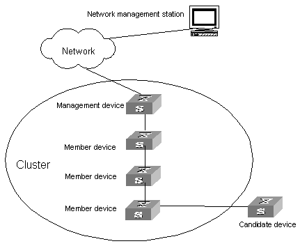
Figure 1-1 Cluster illustration
HGMP V2 has the following advantages:
l It eases the configuration and management of multiple switches: You just need to configure a public IP address for the management device instead of for all the devices in the cluster; and then you can configure and manage all the member devices through the management device without the need to log onto them one by one.
l It provides the topology discovery and display function, which assists in monitoring and maintaining the network.
l It allows you to configure and upgrade multiple switches at the same time.
l It enables you to manage your remotely devices conveniently regardless of network topology and physical distance.
l It saves IP address resource.
HGMP V2 comprises the following three protocols:
l Neighbor discovery protocol (NDP): This protocol is able to discover directly connected neighbor devices and provide information about those devices, including device type, software/hardware version, connecting port, and some other information such as device ID, port full/half duplex mode, product version, and Boot ROM version.
l Neighbor topology discovery protocol (NTDP): This protocol is able to discover network topology and provide network topology information. It collects device and device connection information in your network and allows you to adjust the range of topology discovery.
l Cluster management protocol: This protocol provides the member recognition and member management functions. It works in conjunction with the network management software to implement large-scale network management. Member recognition means that the management device locates and recognizes each member in the cluster so that it can redirects configuration and management commands to the its members. Member management means that the management device manages such events as adding a member and removing a member, and such cluster parameter settings as handshake interval, cluster management VLAN and shared FTP server settings.
Cluster-related configurations will be described in later sections.
1.1.2 Introduction to NDP
NDP is a protocol used to discover adjacent nodes and provide information about them. NDP operates at the data link layer, and therefore it supports different network layer protocols.
NDP is able to discover directly connected neighbors and provide the following neighbor information: device type, software/hardware version, and connecting port. In addition, it may provide the following neighbor information: device ID, port full/half duplex mode, product version, Boot ROM version and so on.
An NDP-enabled device maintains an NDP neighbor table. Each entry in the NDP table can automatically ages out. You can also clear the current NDP information manually to have neighbor information collected again.
An NDP-enabled device regularly broadcasts NDP packet through all its active ports. An NDP packet carries a holdtime field, which indicates how long the receiving devices will keep the NDP packet data. The receiving devices store the information carried in the NDP packet into the NDP table but do not forward the NDP packet. When they receive another NDP packet, if the information carried in the packet is different from the stored one, the corresponding entry in the NDP table is updated, otherwise only the holdtime of the entry is updated.
1.1.3 Introduction to NTDP
NTDP is a protocol used to collect network topology information. NTDP provides information required for cluster management: it collects topology information about the switches within the specified hop count, so as to provide the information of which devices can be added to a cluster.
Based on the neighbor information stored in the neighbor table maintained by NDP, NTDP on the management device advertises NTDP topology collection requests to collect the NDP information of each device in a specific network range as well as the connection information of all its neighbors. The information collected will be used by the management device or the network management software to implement required functions.
When a member device finds any change on its neighbors through its NDP table, it informs the management device through handshake packets, and the management device triggers its NTDP to perform specific topology collection, so that its NTDP can discover topology changes in real time.
& Note:
To implement NTDP, you need to enable NTDP globally and on specific ports on both management device and member/candidate devices, and configure NTDP parameters on only management device. You need not configure NTDP parameters on member/candidate devices because they adopt NTDP parameter settings delivered from the management device when NTDP is running.
1.1.4 Introduction to Cluster
A cluster must have one and only one management device. Note the following when creating a cluster:
l You need to designate a management device for the cluster. The management device of a cluster is the portal of the cluster. That is, any operations from outside the network intended for the member devices of the cluster, such as accessing, configuring, managing, and monitoring, can only be implemented through the management device.
l The management device of the cluster recognizes and controls all the member devices in the cluster, no matter where they are located in the network and how they are connected.
l The management device collects topology information about all member/candidate devices to provide useful information for you to establish the cluster.
l By collecting NDP/NTDP information, the management device learns network topology, so as to manage and monitor network devices.
l Before performing any cluster-related configuration task, you must first enable the cluster function.
& Note:
On the management device, you need to enable the cluster function and configure cluster parameters. On the member/candidate devices, however, you only need to enable the cluster function so that they can be managed by the management device.
Additionally, on the management device, you can configure the FTP server, TFTP server, logging host and SNMP host to be shared by the whole cluster. When a member device in the cluster communicates with an external server, the member device first transmits data to the management device, which then forwards the data to the external server. The management device is the default shared FTP/TFTP server for the cluster; it serves as the shared FTP/TFTP server when no shared FTP/TFTP server is configured for the cluster.
The most important function of clusters is to work in conjunction with the network management software to implement large-scale network management. You can specify a network management interface on the management device of a cluster, through which the network administrator can log onto the management device to manage the devices in the cluster.
& Note:
l By default, the management VLAN interface is used as the network management interface.
l There is only one network management interface on a management device; any newly configured network management interface will overwrite the old one.
1.1.5 Switch Roles for a Cluster
From the point of view of a cluster, switches may play different roles, which depend on their functionality and status. You can specify the role of a switch, or change the role of a switch following some specific rules.
For a cluster, a switch may play one of the three roles: management device, member device, and candidate device.
Table 1-1 Switch roles for a cluster
|
Role |
Configuration |
Functionality |
|
Management device |
l The management device is configured with a public IP address. l You can issue management commands to the management device across the Internet, and the management device will further process your commands. |
l The management device provides a management interface to all switches in the cluster. l It manages member devices by redirecting commands. That is, it forwards commands to their intended member devices for processing. l It has the following functions: neighbor discovery, topology collection, cluster management and cluster status maintenance, and supports FTP Server and SNMP proxies. |
|
Member device |
Normally, a member device is not configured with a public IP address. |
l A member device acts as a member in the cluster. l It has the following functions: neighbor discovery, accepting the management of the management device, running commands forwarded by proxies and reporting failures/logs |
|
Candidate device |
Normally, a candidate device is not configured with a public IP address. |
A candidate device is a switch that does not belong to any cluster; it has cluster capability and can be added to a cluster. |
A switch can change from one role to another according to the following rules:
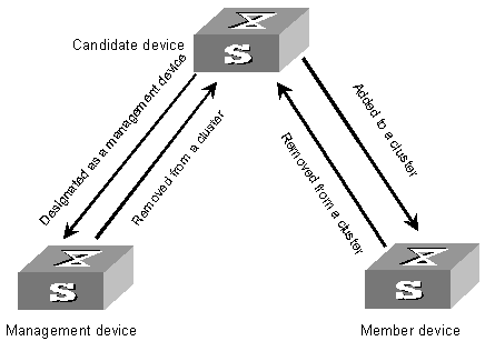
Figure 1-2 Role switching rules
l A candidate device becomes a management device after you designate it as the management device of a cluster (you can do this by building a cluster on the device). Each cluster must have one and only one management device. After you specify the management device of a cluster, the management device discovers and determines candidate devices (by collecting NDP/NTDP information), which you can then add into the cluster through manual configuration.
l A candidate device becomes a member device after being added to a cluster.
l A member device becomes a candidate device after being removed from the cluster.
l The management device becomes a candidate device only after you remove the cluster.
& Note:
After a cluster is set up on an S3100-52P switch, the switch will collect the topology information of the network at the topology collection interval you set and automatically add the candidate devices it discovers into the cluster. As a result, if the topology collection interval is too short (the default interval is 1 minute), the switches acting as candidate devices will not keep in candidate state for a long time – they will change to member devices within a short time. If you do not want the candidate switches to be automatically added into the cluster, you can set the topology collection interval to 0 (by using the ntdp timer command), which specifies not to perform topology collection periodically.
1.2 Cluster Configuration on Management Device
1.2.1 Management Device Cluster Configuration Tasks
Table 1-2 Management device cluster configuration tasks
|
Operation |
Description |
Related section |
|
Enable NDP globally and on specific ports |
Required |
|
|
Configure NDP-related parameters |
Required |
|
|
Enable NTDP globally and on a specific port |
Required |
|
|
Configure NTDP-related parameters |
Required |
|
|
Enable the cluster function |
Required |
Section 1.2.6 Enabling the Cluster Function |
|
Configure cluster parameters |
Required |
Section 1.2.7 Configuring Cluster Parameters |
|
Configure interaction for the cluster |
Required |
|
|
Configure NM interface for the cluster |
Optional |
& Note:
To reduce the risk of being attacked by malicious users against opened socket and enhance switch security, the S3100-52P Ethernet switches provide the following functions, so that a cluster socket is opened only when it is needed:
l Opening UDP port 40000 (used for cluster) only when the cluster function is implemented,
l Closing UDP port 40000 at the same time when the cluster function is closed.
On the management device, the preceding functions are implemented as follows:
l When you create a cluster by using the build or auto-build command, UDP port 40000 is opened at the same time.
l When you remove a cluster by using the undo build or undo cluster enable command, UDP port 40000 is closed at the same time.
1.2.2 Enabling NDP Globally and on Specific Ports
Table 1-3 Enable NDP globally and on specific ports
|
Operation |
Command |
Description |
||
|
Enter system view |
system-view |
— |
||
|
Enable NDP globally |
ndp enable |
Required By default, NDP is enabled globally. |
||
|
Enable NDP on specified Ethernet ports |
In system view |
ndp enable interface port-list |
You must choose one of the two ways. By default, NDP is enabled on a port. |
|
|
In Ethernet port view |
Enter Ethernet port view |
interface interface-type interface-number |
||
|
Enable NDP on the port |
ndp enable |
|||
1.2.3 Configuring NDP-Related Parameters
Table 1-4 Configure NDP-related parameters
|
Operation |
Command |
Description |
|
Enter system view |
system-view |
— |
|
Configure the holdtime of NDP information |
ndp timer aging aging-in-seconds |
Optional By default, the holdtime of NDP information is 180 seconds. |
|
Configure the interval to send NDP packets |
ndp timer hello seconds |
Optional By default, the interval to send NDP packets is 60 seconds. |
1.2.4 Enabling NTDP Globally and on a Specific Port
Table 1-5 Enable NTDP globally and on a specific port
|
Operation |
Command |
Description |
|
Enter system view |
system-view |
— |
|
Enable NTDP globally |
ntdp enable |
Required |
|
Enter Ethernet port view |
interface interface-type interface-number |
— |
|
Enable NTDP on the Ethernet port |
ntdp enable |
Required |
1.2.5 Configuring NTDP-Related Parameters
Table 1-6 Configure NTDP-related parameters
|
Operation |
Command |
Description |
|
Enter system view |
system-view |
— |
|
Configure the range to collect topology information |
ntdp hop hop-value |
Optional By default, the system collects topology information from the devices within three hops. |
|
Configure the device forward delay of topology collection requests |
ntdp timer hop-delay time |
Optional By default, the device forward delay is 200 ms. |
|
Configure the port forward delay of topology collection requests |
ntdp timer port-delay time |
Optional By default, the port forward delay is 20 ms. |
|
Configure the interval to collect topology information periodically |
ntdp timer interval-in-minutes |
Optional By default, the topology collection interval is one minute. |
|
Quit system view |
quit |
— |
|
Start topology collection |
ntdp explore |
Optional |
1.2.6 Enabling the Cluster Function
Table 1-7 Enable the cluster function
|
Operation |
Command |
Description |
|
Enter system view |
system-view |
— |
|
Enable the cluster function globally |
cluster enable |
Optional By default, the cluster function is enabled. |
1.2.7 Configuring Cluster Parameters
I. Manually building a cluster and configuring cluster parameters
Table 1-8 Manually build a cluster and configure cluster parameters
|
Operation |
Command |
Description |
|
Enter system view |
system-view |
— |
|
Specify the management VLAN |
management-vlan vlan-id |
Required By default, VLAN 1 is used as the management VLAN. |
|
Enter cluster view |
cluster |
— |
|
Configure a IP address pool for the cluster |
ip-pool administrator-ip-address { ip-mask | ip-mask-length } |
Required |
|
Build a cluster |
build name |
Required name: cluster name. |
|
Configure a multicast MAC address for the cluster |
cluster-mac H-H-H |
Optional By default, the cluster multicast MAC address is 0180-C200-000A. |
|
Set the interval for the management device to send multicast packets |
cluster-mac syn-interval time-interval |
Optional By default, the interval to send multicast packets is one minutes. |
|
Set the holdtime of member switches |
holdtime seconds |
Optional By default, the holdtime is 60 seconds. |
|
Set the interval to send handshake packets |
timer interval |
Optional By default, the interval to send handshake packets is 10 seconds. |
|
Quit cluster view |
quit |
— |
II. Starting automatic cluster building
Table 1-9 Start automatic cluster building
|
Operation |
Command |
Description |
|
Enter system view |
system-view |
— |
|
Enter cluster view |
cluster |
— |
|
Configure the cluster IP address range |
ip-pool administrator-ip-address { ip-mask | ip-mask-length } |
Required |
|
Start automatic cluster building |
auto-build [ recover ] |
Required Follow prompts to build a cluster. |
1.2.8 Configuring Interaction for the Cluster
Table 1-10 Configure interaction for the cluster
|
Operation |
Command |
Description |
|
Enter system view |
system-view |
— |
|
Enter cluster view |
cluster |
Required |
|
Configure a shared FTP server for the cluster |
ftp-server ip-address |
Optional By default, the management device acts as the shared FTP server. |
|
Configure a shared TFTP server for the cluster |
tftp-server ip-address |
Optional By default, no shared TFTP server is configured. |
|
Configure a shared logging host for the cluster |
logging-host ip-address |
Optional By default, no shared logging host is configured. |
|
Configure a shared SNMP host for the cluster |
snmp-host ip-address |
Optional By default, no shared SNMP host is configured. |
1.2.9 Configuring NM Interface for the Cluster
I. Configuration prerequisites
l The cluster switches are properly connected;
l The shared servers are properly connected to the management switch.
II. Configuration procedure
Table 1-11 Configure NM interface for the cluster
|
Operation |
Command |
Description |
|
Enter system view |
system-view |
— |
|
Enter cluster view |
cluster |
Required |
|
Configure the network management (NM) interface for the cluster |
nm-interface Vlan-interface vlan-id |
Optional By default, the management VLAN interface is used as the NM interface. |
1.3 Cluster Configuration on Member Device
1.3.1 Member Device Cluster Configuration Tasks
Table 1-12 Member device Cluster configuration tasks
|
Operation |
Description |
Related section |
|
Enable NDP globally and on specific ports |
Required |
|
|
Enable NTDP globally and on a specific port |
Required |
|
|
Enable the cluster function |
Required |
Section 1.3.4 Enabling the Cluster Function |
|
Access shared FTP/TFTP server from a member device |
Optional |
& Note:
To reduce the risk of being attacked by malicious users against opened socket and enhance switch security, the S3100-52P Ethernet switches provide the following functions, so that a cluster socket is opened only when it is needed:
l Opening UDP port 40000 (used for cluster) only when the cluster function is implemented,
l Closing UDP port 40000 at the same time when the cluster function is closed.
On member devices, the preceding functions are implemented as follows:
l When you execute the add-member command on the management device to add a candidate device to a cluster, the candidate device changes to a member device and its UDP port 40000 is opened at the same time.
l When you execute the auto-build command on the management device to have the system automatically add candidate devices to a cluster, the candidate devices change to member devices and their UDP port 40000 is opened at the same time.
l When you execute the administrator-address command on a device, the device's UDP port 40000 is opened at the same time.
l When you execute the delete-member command on the management device to remove a member device from a cluster, the member device's UDP port 40000 is closed at the same time.
l When you execute the undo build command on the management device to remove a cluster, UDP port 40000 of all the member devices in the cluster is closed at the same time.
l When you execute the undo administrator-address command on a member device, UDP port 40000 of the member device is closed at the same time.
1.3.2 Enabling NDP Globally and on Specific Ports
Table 1-13 Enable NDP globally and on specific ports
|
Operation |
Command |
Description |
||
|
Enter system view |
system-view |
— |
||
|
Enable NDP globally |
ndp enable |
Required |
||
|
Enable NDP on specified ports |
In system view |
ndp enable interface port-list |
Required You can choose to enable NDP on some ports in system view or enable NDP on a port in Ethernet port view. |
|
|
In Ethernet port view |
Enter Ethernet port view |
interface interface-type interface-number |
||
|
Enable NDP on the port |
ndp enable |
|||
1.3.3 Enabling NTDP Globally and on a Specific Port
Table 1-14 Enable NTDP globally and a specific port
|
Operation |
Command |
Description |
|
Enter system view |
system-view |
— |
|
Enable NTDP globally |
ntdp enable |
Required |
|
Enter Ethernet port view |
interface interface-type interface-number |
— |
|
Enable NTDP on the port |
ntdp enable |
Required |
1.3.4 Enabling the Cluster Function
Table 1-15 Enable the cluster function
|
Operation |
Command |
Description |
|
Enter system view |
system-view |
— |
|
Enable the cluster function globally |
cluster enable |
Optional By default, the cluster function is enabled. |
1.3.5 Accessing Shared FTP/TFTP Server from a Member Device
Perform the following operations in user view on a member device.
Table 1-16 Access shared FTP/TFTP server from a member device
|
Operation |
Command |
Description |
|
Access the shared FTP server of the cluster |
ftp cluster |
Optional |
|
Download a file from the shared TFTP server of the cluster |
tftp cluster get source-file [ destination-file ] |
Optional |
|
Upload a file to the shared TFTP server of the cluster |
tftp cluster put source-file [ destination-file ] |
Optional |
1.4 Cluster Member Configuration
Table 1-17 Cluster member configuration
|
Operation |
Command |
Description |
|
Enter system view |
system-view |
— |
|
Enter cluster view |
cluster |
— |
|
Add a candidate device to the cluster |
add-member [ member-number ] mac-address H-H-H [ password password ] |
Optional |
|
Remove a member device from the cluster |
delete-member member-number |
Optional |
|
Reboot a specified member device |
reboot member { member-number | mac-address H-H-H } [ eraseflash ] |
Optional |
|
Return to system view |
quit |
— |
|
Return to user view |
quit |
— |
|
Switch between management device and member device |
cluster switch-to { member-number | mac-address H-H-H | administrator } |
Optional You can use this command switch to the view of a member device and switch back. |
1.5 Displaying and Maintaining Cluster Configuration
After the above configuration, you can execute the display command in any view to display the configuration and running status of cluster, so as to verify your configuration.
Table 1-18 Display and maintain cluster configuration
|
Operation |
Command |
Description |
|
Display all NDP configuration and running information (including the interval to send NDP packets, the holdtime, and all neighbors discovered) |
display ndp |
You can execute the display command in any view. |
|
Display NDP configuration and running information on specified ports (including the neighbors discovered by NDP on the ports) |
display ndp interface port-list |
|
|
Display global NTDP information |
display ntdp |
|
|
Display device information collected by NTDP |
display ntdp device-list [ verbose ] |
|
|
Display status and statistics information about the cluster |
display cluster |
|
|
Display information about the candidate devices of the cluster |
display cluster candidates [ mac-address H-H-H | verbose ] |
|
|
Display information about the member devices of the cluster |
display cluster members [ member-number | verbose ] |
|
|
Clear NDP statistics on ports |
reset ndp statistics [ interface port-list ] |
You can execute the reset command in user view. |
1.6 Cluster Configuration Example
1.6.1 Basic Cluster Configuration Example
I. Network requirements
Three switches compose a cluster, where:
l An S3100-52P switch serves as the management device.
l The rest are member devices.
Serving as the management device, the S3100-52P switch manages the two member devices. The configuration for the cluster is as follows:
l The two member devices connect to the management device through Ethernet1/0/2 and Ethernet1/0/3.
l The management device connects to the Internet through Ethernet1/0/1.
l Ethernet1/0/1 belongs to VLAN 2, whose interface IP address is 163.172.55.1.
l All the devices in the cluster share the same FTP server and TFTP server.
l The FTP server and TFTP server use the same IP address: 63.172.55.1.
l The NMS and logging host use the same IP address: 69.172.55.4.
II. Network diagram
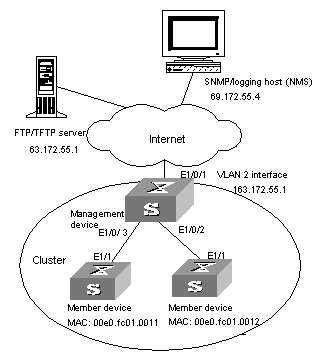
Figure 1-3 Network diagram for HGMP cluster configuration
III. Configuration procedure
1) Configure the member devices (taking one member as an example)
# Enable NDP globally and on Ethernet1/1.
<H3C> system-view
[H3C] ndp enable
[H3C] interface Ethernet 1/1
[H3C-Ethernet1/1] ndp enable
[H3C-Ethernet1/1] quit
# Enable NTDP globally and on Ethernet1/1.
[H3C] ntdp enable
[H3C] interface Ethernet 1/1
[H3C-Ethernet1/1] ntdp enable
[H3C-Ethernet1/1] quit
# Enable the cluster function.
[H3C] cluster enable
2) Configure the management device
# Enable NDP globally and on Ethernet1/0/2 and Ethernet1/0/3.
<H3C> system-view
[H3C] ndp enable
[H3C] interface Ethernet 1/0/2
[H3C-Ethernet1/0/2] ndp enable
[H3C-Ethernet1/0/2] interface Ethernet 1/0/3
[H3C-Ethernet1/0/3] ndp enable
[H3C-Ethernet1/0/3] quit
# Set the holdtime of NDP information to 200 seconds.
[H3C] ndp timer aging 200
# Set the interval to send NDP packets to 70 seconds.
[H3C] ndp timer hello 70
# Enable NTDP globally and on Ethernet1/0/2 and Ethernet1/0/3.
[H3C] ntdp enable
[H3C] interface Ethernet 1/0/2
[H3C-Ethernet1/0/2] ntdp enable
[H3C-Ethernet1/0/2] interface Ethernet 1/0/3
[H3C-Ethernet1/0/3] ntdp enable
[H3C-Ethernet1/0/3] quit
# Set the topology collection range to 2 hops.
[H3C] ntdp hop 2
# Set the member device forward delay for topology collection requests to 150 ms.
[H3C] ntdp timer hop-delay 150
# Set the member port forward delay for topology collection requests to 15 ms.
[H3C] ntdp timer port-delay 15
# Set the interval to collect topology information to 3 minutes.
[H3C] ntdp timer 3
# Enable the cluster function.
[H3C] cluster enable
# Enter cluster view.
[H3C] cluster
[H3C-cluster]
# Configure a private IP address pool for the cluster. The IP address pool contains six IP addresses, starting from 172.16.0.1.
[H3C-cluster] ip-pool 172.16.0.1 255.255.255.248
# Name and build the cluster.
[H3C-cluster] build aaa
[aaa_0.H3C-cluster]
# Add the attached two switches to the cluster.
[aaa_0.H3C-cluster] add-member 1 mac-address 00e0-fc01-0011
[aaa_0.H3C-cluster] add-member 17 mac-address 00e0-fc01-0012
# Set the holdtime of member device information to 100 seconds.
[aaa_0.H3C-cluster] holdtime 100
# Set the interval to send handshake packets to 10 seconds.
[aaa_0.H3C-cluster] timer 10
# Configure the shared FTP server, TFTP server, Logging host and SNMP host for the cluster.
[aaa_0.H3C-cluster] ftp-server 63.172.55.1
[aaa_0.H3C-cluster] tftp-server 63.172.55.1
[aaa_0.H3C-cluster] logging-host 69.172.55.4
[aaa_0.H3C-cluster] snmp-host 69.172.55.4
3) Perform the following operations on the member devices (taking one member as an example)
After adding the devices under the management device to the cluster, perform the following operations on a member device.
# Connect the member device to the remote shared FTP server of the cluster.
<aaa_1.H3C> ftp cluster
# Download the file named aaa.txt from the shared TFTP server of the cluster to the member device.
<aaa_1.H3C> tftp cluster get aaa.txt
# Upload the file named bbb.txt from the member device to the shared TFTP server of the cluster.
<aaa_1.H3C> tftp cluster put bbb.txt
& Note:
l After completing the above configuration, you can execute the cluster switch-to { member-number | mac-address H-H-H } command on the management device to switch to member device view to maintain and manage a member device. After that, you can execute the cluster switch-to administrator command to return to management device view.
l In addition, you can execute the reboot member { member-number | mac-address H-H-H } [ eraseflash ] command on the management device to reboot a member device. For detailed information about these operations, refer to the preceding description in this chapter.
l After the above configuration, you can receive logs and SNMP trap messages of all cluster members on the NMS.
1.6.2 NM Interface Configuration Example
I. Network requirements
l Configure VLAN-interface 2 as the NM interface of the switch;
l Configure VLAN 3 as the management VLAN;
l The IP address of the FTP server is 192.168.4.3;
l The S3100-52P switch is the management switch;
l The S3526E and S2403 switches are member switches.
Table 1-19 Connection information of the management switch
|
VLAN |
IP address |
Connection port |
|
VLAN 3 (connect to S3526E) |
192.168.5.30/24 |
Ethernet 1/0/1 |
|
VLAN 2 (connect to FTP server) |
192.168.4.22/24 |
Ethernet 1/0/2 |
II. Network diagram
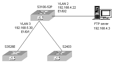
Figure 1-4 Network diagram for NM interface configuration
III. Configuration procedure
# Enter system view and configure VLAN 3 as the management VLAN.
<H3C> system-view
[H3C] management-vlan 3
# Add Ethernet 1/0/1 to VLAN 3.
[H3C] vlan 3
[H3C-vlan3] port Ethernet 1/0/1
[H3C-vlan3] quit
# Set the IP address of VLAN-interface 3 to 192.168.5.30.
[H3C] interface Vlan-interface 3
[H3C-Vlan-interface3] ip address 192.168.5.30 255.255.255.0
[H3C-Vlan-interface3] quit
# Add Ethernet 1/0/2 to VLAN 2.
[H3C] vlan 2
[H3C-vlan2] port Ethernet 1/0/2
[H3C-vlan2] quit
# Set the IP address of VLAN-interface 2 to 192.168.4.22.
[H3C] interface Vlan-interface 2
[H3C-Vlan-interface2] ip address 192.168.4.22 255.255.255.0
[H3C-Vlan-interface2] quit
# Configure VLAN-interface 2 as the NM interface.
[H3C] cluster
[H3C-cluster] nm-interface Vlan-interface 2
