- Table of Contents
-
- H3C S3100-52P Ethernet Switch Operation Manual-Release 1500(V1.02)
- 00-1Cover
- 00-2Overview
- 01-CLI Operation
- 02-Login Operation
- 03-Configuration File Management Operation
- 04-VLAN Operation
- 05-IP Address and Performance Confiugration Operation
- 06-GVRP Operation
- 07-Port Basic Configuration Operation
- 08-Link Aggregation Operation
- 09-Port Isolation Operation
- 10-DLDP Operation
- 11-MAC Address Table Operation
- 12-MSTP Operation
- 13-Multicast Operation
- 14-Routing Protocol Operation
- 15-802.1x Operation
- 16-AAA-RADIUS-HWTACACS Operation
- 17-Centralized MAC Address Authentication Operation
- 18-DHCP Operation
- 19-ARP Operation
- 20-ACL Operation
- 21-QoS Operation
- 22-Mirroring Operation
- 23-Cluster Operation
- 24-SNMP and RMON Operation
- 25-NTP Operation
- 26-SSH Terminal Service Operation
- 27-File System Management Operation
- 28-FTP and TFTP Operatio
- 29-Information Center Operation
- 30-System Maintenance and Debugging Operation
- 31-VLAN VPN Operation
- 32-HWPing Operation
- 33-DNS Operation
- 34-Appendix
- Related Documents
-
| Title | Size | Download |
|---|---|---|
| 13-Multicast Operation | 980.23 KB |
Table of Contents
1.1.1 Information Transmission in the Unicast Mode
1.1.2 Information Transmission in the Broadcast Mode
1.1.3 Information Transmission in the Multicast Mode
1.1.4 Advantages and Applications of Multicast
1.3 Forwarding Mechanism of Multicast Packets
Chapter 2 IGMP Snooping Configuration
2.1.1 IGMP Snooping Fundamentals
2.1.2 IGMP Snooping Implementation
2.2 IGMP Snooping Configuration
2.2.3 Enabling IGMP Fast Leave
2.2.4 Configuring IGMP Snooping Filtering ACL
2.2.5 Configuring to Limit Number of Multicast Groups on a Port
2.2.6 Configuring IGMP Querier
2.2.7 Configuring Multicast VLAN
2.3 Displaying and Maintaining IGMP Snooping
2.4 IGMP Snooping Configuration Example
2.5 Troubleshooting IGMP Snooping
Chapter 3 Common Multicast Configuration
3.2 Configuring Suppression on the Multicast Source Port
3.3 Displaying Common Multicast Configuration
Chapter 4 Multicast MAC Address Entry Configuration
4.2 Configuring a Multicast MAC Address Entry
4.3 Displaying and Maintaining Multicast MAC Address
Chapter 5 Unknown Multicast Packet Drop Configuration
5.2 Unknown Multicast Packet Drop Configuration
Chapter 1 Multicast Overview
1.1 Multicast Overview
With development of networks on the Internet, more and more interaction services such as data, voice, and video services are running on the networks. In addition, services highly dependent on bandwidth and real-time data interaction, such as e-commerce, web conference, online auction, video on demand (VoD), and tele-education have come into being. These services have higher requirements for information security, legal use of paid services, and network bandwidth.
1.1.1 Information Transmission in the Unicast Mode
In unicast, the system establishes a separate data transmission channel for each user requiring this information, and sends separate copy information to the user, as shown in Figure 1-1:
Figure 1-1 Information transmission in the unicast mode
Assume that users B, D and E need this information. The source server establishes transmission channels for the devices of these users respectively. As the transmitted traffic over the network is in direct proportion to the number of users that receive this information, when a large number of users need this information, the server must send many pieces of information with the same content to the users. Therefore, the limited bandwidth becomes the bottleneck in information transmission. This shows that unicast is not good for the transmission of a great deal of information.
1.1.2 Information Transmission in the Broadcast Mode
When you adopt broadcast, the system transmits information to all users on a network. Any user on the network can receive the information, no matter the information is needed or not. Figure 1-2 shows information transmission in broadcast mode.
Figure 1-2 Information transmission in the broadcast mode
Assume that users B, D, and E need the information. The source server broadcasts this information through routers, and users A and C on the network also receive this information. The security and payment of the information cannot be guaranteed.
As we can see from the information transmission process, the security and legal use of paid service cannot be guaranteed. In addition, when only a small number of users on the same network need the information, the utilization ratio of the network resources is very low and the bandwidth resources are greatly wasted.
1.1.3 Information Transmission in the Multicast Mode
As described in the previous sections, unicast is suitable for networks with sparsely distributed users, whereas broadcast is suitable for networks with densely distributed users. When the number of users requiring information is not certain, unicast and broadcast deliver a low efficiency.
Multicast solves this problem. When some users on a network require specified information, the multicast information sender (namely, the multicast source) sends the information only once. With tree-type routes established for multicast data packets through a multicast routing protocol, the packets are duplicated and distributed at the nearest nodes, as shown in Figure 1-3:
Figure 1-3 Information transmission in the multicast mode
Assume that users B, D and E need the information. To transmit the information to the right users, it is necessary to group users B, D and E into a receiver set. The routers on the network duplicate and distribute the information based on the distribution of the receivers in this set. Finally, the information is correctly delivered to users B, D, and E.
The advantages of multicast over unicast are as follows:
l No matter how many receivers exist, there is only one copy of the same multicast data flow on each link.
l With the multicast mode used to transmit information, an increase of the number of users does not add to the network burden remarkably.
The advantages of multicast over broadcast are as follows:
l A multicast data flow can be sent only to the receiver that requires the data.
l Multicast brings no waste of network resources and makes proper use of bandwidth.
In the multicast mode, network components can be divided in to the following roles:
l An information sender is referred to as a multicast source.
l Multiple receivers receiving the same information form a multicast group. Multicast group is not limited by physical area.
l Each receiver receiving multicast information is a multicast group member.
l A router providing multicast routing is a multicast router. The multicast router can be a member of one or multiple multicast groups, and it can also manage members of the multicast groups.
For a better understanding of the multicast concept, you can assimilate a multicast group to a TV channel. A TV station is a multicast source. It sends data to the channel. The audiences are the receivers. After turning on a TV set (a computer), they can select a channel to receive a program (namely join a group) and then watch the program. Therefore, a multicast group should be an agreement between the sender and the receivers, like the frequency of a channel.
![]() Caution:
Caution:
A multicast source does not necessarily belong to a multicast group. A multicast source sends data to a multicast group, and it is not necessarily a receiver. Multiple multicast sources can send packets to the same multicast group at the same time.
1.1.4 Advantages and Applications of Multicast
I. Advantages of multicast
Advantages of multicast include:
l Enhanced efficiency: Multicast decreases network traffic and reduces server load and CPU load.
l Optimal performance: Multicast reduces redundant traffic.
l Distributive application: Multicast makes multiple-point application possible.
II. Application of multicast
The multicast technology effectively addresses the issue of point-to-multipoint data transmission. By enabling high-efficiency point-to-multipoint data transmission, over an IP network, multicast greatly saves network bandwidth and reduces network load.
Multicast provides the following applications:
l Applications of multimedia and flow media, such as Web TV, Web radio, and real-time video/audio conferencing.
l Communication for training and cooperative operations, such as remote education.
l Database and financial applications (stock), and so on.
l Any point-to-multiple-point data application.
1.2 Multicast Architecture
The purpose of IP multicast is to transmit information from a multicast source to receivers in the multicast mode and to satisfy information requirements of receivers. You should be concerned about:
l Host registration: What receivers reside on the network?
l Technologies of discovering a multicast source: Which multicast source should the receivers receive information from?
l Multicast addressing mechanism: Where should the multicast source transports information?
l Multicast routing: How is information transported?
IP multicast is a kind of peer-to-peer service. Based on the protocol layer sequence from bottom to top, the multicast mechanism contains addressing mechanism, host registration, multicast routing, and multicast application, as shown in Figure 1-4:
Figure 1-4 Architecture of the multicast mechanism
The multicast addressing mechanism involves the planning of multicast addresses. Host registration and multicast routing are implemented based on the IP multicast protocol. Multicast application software is not described in this chapter.
l Addressing mechanism: Information is sent from a multicast source to a group of receivers through multicast addresses.
l Host registration: A receiving host joins and leaves a multicast group dynamically to implement membership registration.
l Multicast routing: A router or switch establishes a packet distribution tree and transports packets from a multicast source to receivers.
1.2.1 Multicast Address
As receivers are multiple hosts in a multicast group, you should be concerned about the following questions:
l What destination should the information source send the information to in the multicast mode?
l How to select the destination address, that is, how does the information source know who the user is?
These questions are about multicast addressing. To enable the communication between the information source and members of a multicast group (a group of information receivers), network-layer multicast addresses, namely, IP multicast addresses must be provided. In addition, a technology must be available to map IP multicast addresses to link-layer MAC multicast addresses. The following sections describe these two types of multicast addresses:
I. IP multicast address
Internet Assigned Numbers Authority (IANA) categorizes IP addresses into five classes: A, B, C, D, and E. Unicast packets use IP addresses of Class A, B, and C based on network scales. Class D IP addresses are used as destination addresses of multicast packets. Class D address must not appear in the IP address field of a source IP address of IP packets. Class E IP addresses are reserved for future use.
In unicast data transport, a data packet is transported hop by hop from the source address to the destination address. In an IP multicast environment, there are a group of destination addresses (called group address), rather than one address. All the receivers join a group. Once they join the group, the data sent to this group of addresses starts to be transported to the receivers. All the members in this group can receive the data packets. This group is a multicast group.
A multicast group has the following characteristics:
l The membership of a group is dynamic. A host can join and leave a multicast group at any time.
l A multicast group can be either permanent or temporary.
l A multicast group whose addresses are assigned by IANA is a permanent multicast group. It is also called reserved multicast group.
Note that:
l The IP addresses of a permanent multicast group keep unchanged, while the members of the group can be changed.
l There can be any number of, or even zero, members in a permanent multicast group.
l Those IP multicast addresses not assigned to permanent multicast groups can be used by temporary multicast groups.
Class D IP addresses range from 224.0.0.0 to 239.255.255.255. For details, see Table 1-1.
Table 1-1 Range and description of Class D IP addresses
|
Class D address range |
Description |
|
224.0.0.0 to 224.0.0.255 |
Reserved multicast addresses (IP addresses for permanent multicast groups). The IP address 224.0.0.0 is reserved. Other IP addresses can be used by routing protocols. |
|
224.0.1.0 to 231.255.255.255 233.0.0.0 to 238.255.255.255 |
Available any-source multicast (ASM) multicast addresses (IP addresses for temporary groups). They are valid for the entire network. |
|
232.0.0.0 to 232.255.255.255 |
Available source-specific multicast (SSM) multicast group addresses. |
|
239.0.0.0 to 239.255.255.255 |
Local management multicast addresses, which are for specific local use only. |
As specified by IANA, the IP addresses ranging from 224.0.0.0 to 224.0.0.255 are reserved for network protocols on local networks. The following table lists commonly used reserved IP multicast addresses:
Table 1-2 Reserved IP multicast addresses
|
Class D address range |
Description |
|
224.0.0.1 |
Address of all hosts |
|
224.0.0.2 |
Address of all multicast routers |
|
224.0.0.3 |
Unassigned |
|
224.0.0.4 |
Distance vector multicast routing protocol (DVMRP) routers |
|
224.0.0.5 |
Open shortest path first (OSPF) routers |
|
224.0.0.6 |
Open shortest path first designated routers (OSPF DR) |
|
224.0.0.7 |
Shared tree routers |
|
224.0.0.8 |
Shared tree hosts |
|
224.0.0.9 |
RIP-2 routers |
|
224.0.0.11 |
Mobile agents |
|
224.0.0.12 |
DHCP server/relay agent |
|
224.0.0.13 |
All protocol independent multicast (PIM) routers |
|
224.0.0.14 |
Resource reservation protocol (RSVP) encapsulation |
|
224.0.0.15 |
All core-based tree (CBT) routers |
|
224.0.0.16 |
The specified subnetwork bandwidth management (SBM) |
|
224.0.0.17 |
All SBMS |
|
224.0.0.18 |
Virtual router redundancy protocol (VRRP) |
|
224.0.0.19 to 224.0.0.255 |
Other protocols |
& Note:
Like having reserved the private network segment 10.0.0.0/8 for unicast, IANA has also reserved the network segments ranging from 239.0.0.0 to 239.255.255.255 for multicast. These are administratively scoped addresses. With the administratively scoped addresses, you can define the range of multicast domains flexibly to isolate IP addresses between different multicast domains, so that the same multicast address can be used in different multicast domains without causing collisions.
II. Ethernet multicast MAC address
When a unicast IP packet is transported in an Ethernet network, the destination MAC address is the MAC address of the receiver. When a multicast packet is transported in an Ethernet network, a multicast MAC address is used as the destination address because the destination is a group with an uncertain number of members.
As stipulated by IANA, the high-order 24 bits of a multicast MAC address are 0x01005e, while the low-order 23 bits of a MAC address are the low-order 23 bits of the multicast IP address. Figure 1-5 describes the mapping relationship:
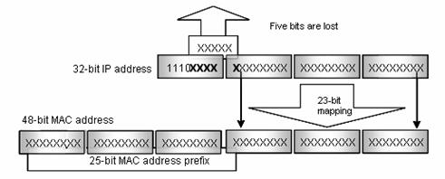
Figure 1-5 Mapping relationship between multicast IP address and multicast MAC address
The high-order four bits of the IP multicast address are 1110, representing the multicast ID. Only 23 bits of the remaining 28 bits are mapped to a MAC address. Thus, five bits of the multicast IP address are lost. As a result, 32 IP multicast addresses are mapped to the same MAC address.
1.2.2 IP Multicast Protocols
IP multicast protocols include the multicast group management protocol and the multicast routing protocol. Figure 1-6 describes the positions of the protocols related to multicast in the network.
Figure 1-6 Positions of protocols related to multicast
I. Multicast group management protocol
Internet group membership protocol (IGMP) is adopted between hosts and multicast routers. This protocol defines the mechanism of establishing and maintaining group membership between hosts and multicast routers.
II. Multicast routing protocols
A multicast routing protocol operates between multicast routers to establish and maintain multicast routes and forward multicast packets accurately and effectively. A multicast route establishes a loop-free data transport path from a data source to multiple receivers. The task of multicast routing protocol is to establish a distribution tree structure. Multicast routers can establish the data transmission path (namely, distribution tree) in many ways.
Like unicast routes, multicast routes come in intra-domain routes and inter-domain routes. Intra-domain multicast routes are quite mature now. Protocol independent multicast (PIM) is the most commonly used protocol currently. It can cooperate with any unicast routing protocol.
1.3 Forwarding Mechanism of Multicast Packets
In a multicast model, a multicast source host transports information to the host group, which is identified by the multicast group address in the destination address field of an IP data packet. Unlike a unicast model, a multicast model must forward data packets to multiple external interfaces so that all receiver sites can receive the packets. Therefore the forwarding process of multicast is more complicated than that of unicast.
Based on source addresses, multicast routers judge whether multicast packets come from specified interfaces; that is, RPF check determines whether inbound interfaces are correct by comparing the interfaces that the packets reach with the interfaces that the packets should reach. If the router resides on a shortest path tree (SPT), the interface that multicast packets should reach points to the multicast source. If the router resides on a rendezvous point tree (RPT), the interface that multicast packets should reach points to the rendezvous point (RP). When multicast data packets reach the router, if RPF check passes, the router forwards the data packets based on multicast forwarding entries; otherwise, the data packets are dropped.
Chapter 2 IGMP Snooping Configuration
2.1 Overview
2.1.1 IGMP Snooping Fundamentals
Internet group management protocol snooping (IGMP Snooping) is a multicast control mechanism running on Layer 2 switches. It is used to manage and control multicast groups.
When the IGMP messages transferred from the hosts to the router pass through the Layer 2 switch, the switch uses IGMP Snooping to analyze and process the IGMP messages, as shown in Table 2-1.
Table 2-1 IGMP message processing on the switch
|
Received message type |
Sender |
Receiver |
Switch processing |
|
IGMP host report message |
Host |
Switch |
Add the host to the corresponding multicast group. |
|
IGMP leave message |
Host |
Switch |
Remove the host from the multicast group. |
By listening to IGMP messages, the switch establishes and maintains MAC multicast address tables at data link layer, and uses the tables to forward the multicast packets delivered from the router.
As shown in Figure 2-1, multicast packets are broadcast at Layer 2 when IGMP Snooping is disabled and multicast (not broadcast) at Layer 2 when IGMP Snooping is enabled.
Figure 2-1 Multicast packet transmission with or without IGMP Snooping enabled
2.1.2 IGMP Snooping Implementation
I. IGMP Snooping terminologies
Before going on, we first describe the following terms involved in IGMP Snooping:
l Router port: the switch port directly connected to the multicast router.
l Multicast member port: a switch port connected to a multicast group member (a host in a multicast group).
l MAC multicast group: a multicast group identified by a MAC multicast address and maintained by the switch.
The following three timers are closely associated with IGMP snooping.
Table 2-2 IGMP Snooping timers
|
Timer |
Setting |
Packet normally received before timeout |
Timeout action on the switch |
|
Router port aging timer |
Aging time of the router port |
IGMP general query message |
Consider that this port is not a router port any more. |
|
Multicast member port aging timer |
Aging time of the multicast member ports |
IGMP message/PIM message/Dvmrp Probe message |
Send an IGMP group-specific query message to the multicast member port. |
|
Query response timer |
Query response timeout time |
IGMP report message |
Remove the port from the member port list of the multicast group. |
II. Layer 2 multicast with IGMP Snooping
The switch runs IGMP Snooping to listen to IGMP messages and map the host, the port corresponding to the host, and the corresponding multicast MAC address.
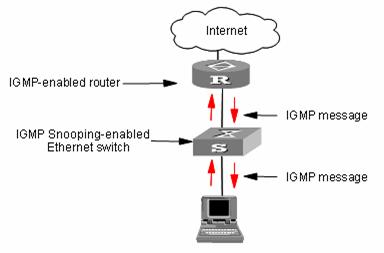
Figure 2-2 IGMP Snooping implementation
To implement Layer 2 multicast, the switch processes four different types of IGMP messages it received, as shown in Table 2-3.
Table 2-3 IGMP Snooping messages
|
Message |
Sender |
Receiver |
Purpose |
Switch action |
|||||
|
IGMP general query message |
Multicast router and multicast switch |
Multicast member switch and host |
Query if the multicast groups contain any member |
Check if the message comes from the original router port |
If yes, reset the aging timer of the router port |
||||
|
If not, notify the multicast router that a member is in a multicast group and start the aging timer for the router port |
|||||||||
|
IGMP group-specific query message |
Multicast router and multicast switch |
Multicast member switch and host |
Query if a specific IGMP multicast group contains any member |
Send an IGMP group-specific query message to the IP multicast group being queried. |
|||||
|
IGMP host report message |
Host |
Multicast router and multicast switch |
Apply for joining a multicast group, or respond to an IGMP query message |
Check if the IP multicast group has a corresponding MAC multicast group |
If yes, check if the port exists in the MAC multicast group |
If yes, add the IP multicast group address to the MAC multicast group table. |
|||
|
If not, add the port to the MAC multicast group, reset the aging timer of the port and check if the corresponding IP multicast group exists. |
If yes, add the port to the IP multicast group. |
||||||||
|
If not, create an IP multicast group and add the port to it. |
|||||||||
|
If not: Create a MAC multicast group and notify the multicast router that a member is ready to join the multicast group. Add the port to the MAC multicast group and start the aging timer of the port. Add all ports in the VLAN owning this port to the forward port list of the MAC multicast group. Add the port to the IP multicast group. |
|||||||||
|
IGMP leave message |
Host |
Multicast router and multicast switch |
Notify the multicast router and multicast switch that the host is leaving its multicast group. |
Multicast router and multicast switch send IGMP group-specific query packet(s) to the multicast group whose member host sends leave packets to check if the multicast group has any members and enable the corresponding query timer. |
If no response is received from the port before the timer times out, the switch will check whether the port corresponds to a single MAC multicast group. l If yes, remove the corresponding MAC multicast group and IP multicast group l If no, remove only those entries that correspond to this port in the MAC multicast group, and remove the corresponding IP multicast group entries |
||||
|
If no response is received from the multicast group before the timer times out, notify the router to remove this multicast group node from the multicast tree |
|||||||||
![]() Caution:
Caution:
An IGMP-Snooping-enabled Ethernet switch judges whether the multicast group exists when it receives an IGMP leave packet sent by a host in a multicast group. If this multicast group does not exist, the switch will drop the IGMP leave packet instead of forwarding it.
2.2 IGMP Snooping Configuration
The following table lists all the IGMP Snooping configuration tasks:
Table 2-4 IGMP Snooping configuration tasks
|
Operation |
Description |
Related section |
|
Enable IGMP Snooping |
Required |
Section 2.2.1 "Enabling IGMP Snooping" |
|
Configure timers |
Optional |
Section 2.2.2 "Configuring Timers" |
|
Enable IGMP fast leave |
Optional |
Section 2.2.3 "Enabling IGMP Fast Leave" |
|
Configure IGMP Snooping filter |
Optional |
Section 2.2.4 "Configuring IGMP Snooping Filtering ACL" |
|
Configure to limit ports passing multicast group |
Optional |
Section 2.2.5 "Configuring to Limit Number of Multicast Groups on a Port" |
|
Configure IGMP Snooping queriers |
Optional |
Section 2.2.6 "Configuring IGMP Querier" |
|
Configure multicast VLAN |
Optional |
Section 2.2.7 "Configuring Multicast VLAN" |
2.2.1 Enabling IGMP Snooping
You can use the command here to enable IGMP Snooping so that it can establish and maintain MAC multicast group forwarding tables at Layer 2.
Table 2-5 Enable IGMP Snooping
|
Operation |
Command |
Description |
|
Enter system view |
system-view |
— |
|
Enable IGMP Snooping globally |
igmp-snooping enable |
Required By default, IGMP Snooping is disabled globally. |
|
Enter VLAN view |
vlan vlan-id |
— |
|
Enable IGMP Snooping on the VLAN |
igmp-snooping enable |
Required By default, IGMP Snooping is disabled on the VLAN. |
![]() Caution:
Caution:
Before configuring IGMP Snooping in VLAN view, you must enable IGMP Snooping globally in system view. Otherwise, the IGMP Snooping feature cannot be enabled in VLAN view.
2.2.2 Configuring Timers
This configuration task is to manually configure the aging timer of the router port, the aging timer of the multicast member ports, and the query response timer.
l If the switch receives no general IGMP query message from a router within the aging time of the router port, the switch removes the router port from the port member lists of all MAC multicast groups.
l If the switch receives no IGMP host report message, it sends an IGMP group-specific query packet to the port and enable the query response timer of the IP multicast group.
l If the switch receives no IGMP host report message within the aging time of the member port, it sends IGMP group-specific query to the port and enables the query response timer of the IP multicast group.
|
Operation |
Command |
Description |
|
Enter system view |
system-view |
— |
|
Configure the aging timer of the router port |
igmp-snooping router-aging-time seconds |
Optional By default, the aging time of the router port is 105 seconds. |
|
Configure the query response timer |
igmp-snooping max-response-time seconds |
Optional By default, the query response timeout time is 10 seconds. |
|
Configure the aging timer of the multicast member port |
igmp-snooping host-aging-time seconds |
Optional By default, the aging time of multicast member ports is 260 seconds |
2.2.3 Enabling IGMP Fast Leave
Normally, when receiving an IGMP Leave message, Switch does not immediately remove the port from the multicast group but sends an IGMP group-specific query message. If no response is received in a given period, it then removes the port from the multicast group.
If IGMP fast leave processing is enabled, when receiving an IGMP Leave message, Switch immediately removes the port from the multicast group. When a port has only one user, enabling IGMP fast leave processing on the port can save bandwidth.
Table 2-7 Enable the IGMP fast leave processing
|
Operation |
Command |
Description |
|
Enter system view |
system-view |
— |
|
Enter Ethernet port view |
interface interface-type interface-number |
— |
|
Enable the fast leave from the specific VLAN for a port |
igmp-snooping fast-leave [ vlan vlan-list ] |
Required By default, the fast leave from the multicast group for a port is disabled. |
2.2.4 Configuring IGMP Snooping Filtering ACL
You can configure multicast filtering ACLs on the switch ports connected to user ends so as to use the IGMP Snooping filter function to limit the multicast streams that the users can access. With this function, you can treat different VoD users in different ways by allowing them to access the multicast streams in different multicast groups.
In practice, when a user orders a multicast program, an IGMP report message is generated. When the message arrives at the switch, the switch examines the multicast filtering ACL configured on the access port to determine if the port can join the corresponding multicast group or not. If yes, it adds the port to the forward port list of the multicast group. If not, it drops the IGMP report message and does not forward the corresponding data stream to the port. In this way, you can control the multicast streams that users can access.
Make sure that ACL rules have been configured before configuring this feature.
Table 2-8 Configure IGMP Snooping filtering ACL
|
Operation |
Command |
Description |
|
Enter system view |
system-view |
— |
|
Enable IGMP Snooping filter |
igmp-snooping group-policy acl-number [ vlan vlan-list ] |
Required l You can configure the ACL to filter the IP addresses of corresponding multicast group. l By default, the multicast filtering feature is disabled. |
|
Enter Ethernet port view |
interface interface-type interface-number |
— |
|
Configure the multicast filtering feature on the port |
igmp-snooping group-policy acl-number [ vlan vlan-list ] |
Optional l You can configure the ACL to filter the IP addresses of corresponding multicast group. l By default, the multicast filtering feature is disabled. |
2.2.5 Configuring to Limit Number of Multicast Groups on a Port
With a limit imposed on the number of multicast groups on the switch port, users can no longer have as many multicast groups as they want when demanding multicast group programs. In this way, the bandwidth on the port is controlled.
Table 2-9 Configure to limit the number of multicast groups on a port
|
Operation |
Command |
Description |
|
Enter system view |
system-view |
— |
|
Enter Ethernet port view |
interface interface-type interface-number |
— |
|
Limit the number of multicast groups on a port |
igmp-snooping group-limit limit [ vlan vlan-list [ overflow-replace ] ] |
Required The number of multicast groups on a port is not limited by default. |
2.2.6 Configuring IGMP Querier
In an IGMP-enabled multicast network, a query multicast router or Layer 3 multicast switch is specifically responsible for sending IGMP query packets.
However, the Layer 2 multicast switch does not support the IGMP feature. Therefore, the Layer 2 multicast switch cannot implement the querier feature and cannot send general group query packets. By configuring IGMP Snooping queriers, you can enable the Layer 2 multicast switch to send general group query packets actively at data link layer, and thereby establish and maintain the multicast forwarding entries.
Additionally, you can enable the Layer 2 switch to send the source addresses, maximum query response time, and query interval of general group query packets,
Table 2-10 Configure IGMP Snooping querier
|
Operation |
Command |
Description |
|
Enter system view |
system-view |
— |
|
Enable the IGMP Snooping feature in system view |
igmp-snooping enable |
Required The IGMP Snooping feature is disabled by default. |
|
Enter VLAN view |
vlan vlan-id |
— |
|
Enable the IGMP Snooping feature in VLAN view |
igmp-snooping enable |
Required By default, the IGMP Snooping feature is disabled. |
|
Configure the IGMP Snooping querier feature |
igmp-snooping querier |
Required The IGMP Snooping querier feature is disabled by default. |
|
Configure the interval of sending general query packets |
igmp-snooping query-interval seconds |
Optional By default, the interval of sending general query packets is 60 seconds. |
|
Configure the source IP address to send general query packets |
igmp-snooping general-query source-ip { current-interface | ip-address } |
Optional By default, the source IP address to send general query packets is 0.0.0.0. |
2.2.7 Configuring Multicast VLAN
In an old multicast mode, when users in different VLANs order the same multicast group, the multicast stream is copied to each of the VLANs. This mode wastes a lot of bandwidth.
By configuring a multicast VLAN, adding switch ports to the multicast VLAN and enabling IGMP Snooping, you can make users in different VLANs share the same multicast VLAN. This saves bandwidth since multicast streams are transmitted only within the multicast VLAN, and also guarantees security because the multicast VLAN is isolated from user VLANs.
Multicast VLAN is mainly used in Layer 2 switching, but you must make corresponding configuration on the Layer 3 switch.
Perform the following configuration to configure multicast VLAN.
Table 2-11 Configure multicast VLAN on Layer 3 switch
|
Operation |
Command |
Description |
|
Enter system view |
system-view |
— |
|
Create a multicast VLAN and enter VLAN view |
vlan vlan-id |
Create the multicast VLAN to be configured. |
|
Exit VLAN view |
quit |
— |
|
Create a multicast VLAN interface and enter VLAN interface view |
interface Vlan-interface vlan-id |
— |
|
Enable IGMP |
igmp enable |
Required By default, the IGMP feature is disabled. |
|
Exit VLAN interface view |
quit |
— |
|
Enter the view of the Ethernet port connected to the Layer 2 switch |
interface interface-type interface-number |
— |
|
Define the port as a trunk or hybrid port |
port link-type { trunk | hybrid } |
Required |
|
Specify the VLANs to be allowed to pass through the Ethernet |
port hybrid vlan vlan-id-list { tagged | untagged } |
Required The multicast VLAN defined on the Layer 2 switch must be included and set as tagged. |
|
port trunk pvid vlan vlan-list |
Table 2-12 Configure multicast VLAN on Layer 2 switch
|
Operation |
Command |
Description |
|
Enter system view |
system-view |
— |
|
Enable IGMP Snooping globally |
igmp-snooping enable |
Required |
|
Enter VLAN view |
vlan vlan-id |
vlan-id is a VLAN ID. |
|
Enable IGMP Snooping on the VLAN |
igmp-snooping enable |
Required By default, the IGMP Snooping feature is disabled |
|
Enable multicast VLAN |
service-type multicast |
Required |
|
Exit VLAN view |
quit |
— |
|
Enter the view of the Ethernet port connected to the Layer 3 switch |
interface interface-type interface-number |
— |
|
Define the port as a trunk or hybrid port |
port link-type { trunk | hybrid } |
— |
|
Specify the VLANs to be allowed to pass through the Ethernet |
port hybrid vlan vlan-list { tagged | untagged } |
The multicast VLAN must be included and set as tagged. |
|
port trunk pvid vlan vlan-list |
||
|
Enter the view of the Ethernet port connected to a user device |
interface interface-type interface-number |
— |
|
Define the port as a hybrid port |
port link-type hybrid |
Required |
|
Specify the VLANs to be allowed to pass the port |
port hybrid vlan vlan-id-list { tagged | untagged } |
Required The multicast VLAN must be included and set as untagged. |
& Note:
l One port can belong to only one multicast VLAN.
l The port connected to a user end can only be a hybrid port.
l The multicast member port must be in the same VLAN with the router port. Otherwise, the multicast member port cannot receive multicast packets.
l When a router port is added to a multicast VLAN, the router port must be set as a Trunk port or tagged Hybrid port. Otherwise, all the multicast member ports in this multicast VLAN cannot receive multicast packets.
l When the multicast VLAN is set up, all IGMP host report messages are broadcast in the multicast VLAN only. For a multicast member port of a non-multicast VLAN, its VLAN interface cannot establish the corresponding Layer 2 multicast entry. Therefore, you are recommended to delete the port from the multicast VLAN.
2.3 Displaying and Maintaining IGMP Snooping
After the configuration above, you can execute the display command in any view to verify the configuration by checking the displayed information.
You can execute the reset command in user view to clear the statistics information about IGMP Snooping.
Table 2-13 Display information about IGMP Snooping
|
Command |
Description |
|
|
Display the current IGMP Snooping configuration |
display igmp-snooping configuration |
You can execute the display commands in any view. |
|
Display IGMP Snooping message statistics |
display igmp-snooping statistics |
|
|
Display IP and MAC multicast groups in one or all VLANs |
display igmp-snooping group [ vlan vlanid ] |
|
|
Clear IGMP Snooping statistics |
reset igmp-snooping statistics |
You can execute the reset command in user view. |
2.4 IGMP Snooping Configuration Example
2.4.1 Example 1
Configure IGMP Snooping on a switch.
I. Network requirements
Connect the router port on the switch to the router, and connect non-router ports that belong to VLAN 10 to user PCs. Enable IGMP Snooping on the switch.
II. Network diagram
Figure 2-3 Network diagram for IGMP Snooping configuration
III. Configuration procedure
# Enable IGMP Snooping in system view.
<H3C> system-view
[H3C] igmp-snooping enable
# Enable IGMP Snooping on VLAN 10.
[H3C] vlan 10
[H3C-vlan10] igmp-snooping enable
2.4.2 Example 2
Configure multicast VLAN on Layer 2 and Layer 3 switches.
I. Network requirements
The multicast source is Workstation. Switch A forwards the multicast data flows that the multicast source sends. The multicast data flows are forwarded by the Layer 2 switch Switch B to the end user PC1 and PC2.
Table 2-14 describes the network devices involved in this example and the configurations you should make on them.
Table 2-14 Network devices and their configurations
|
Device |
Description |
|
|
Switch A |
Layer 3 switch |
The interface IP address of VLAN 20 is 168.10.1.1. Ethernet1/0/1 is connected to the workstation and belongs to VLAN 20. VLAN 10 is the multicast VLAN. Ethernet1/0/5 belongs to VLAN 2, Ethernet1/0/6 belongs to VLAN 3, and Ethernet1/0/10 is connected to Switch B. |
|
Switch B |
Layer 2 switch |
VLAN 2 contains Ethernet1/0/1 and VLAN 3 contains Ethernet1/0/2. The two ports are connected to PC1 and PC2, respectively. Ethernet1/0/10 is connected to Switch A. |
|
PC 1 |
User 1 |
PC1 is connected to Ethernet1/0/1 on Switch B. |
|
PC 2 |
User 2 |
PC2 is connected to Ethernet1/0/2 on Switch B. |
Configure a multicast VLAN, so that the users in VLAN 2 and VLAN 3 can receive multicast streams through the multicast VLAN.
II. Network diagram
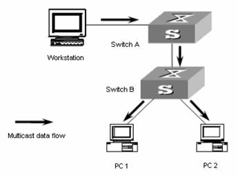
Figure 2-4 Network diagram for multicast VLAN configuration
III. Configuration procedure
The following configuration is based on the prerequisite that the devices are properly connected and all the required IP addresses are already configured.
1) Configure Switch A:
# Set the interface IP address of VLAN 20 to 168.10.1.1 and enable the PIM DM protocol on the VLAN interface.
<SwitchA> system-view
[SwitchA] multicast routing-enable
[SwitchA] vlan 20
[SwitchA-vlan20] interface Vlan-interface 20
[SwitchA-Vlan-interface20] ip address 168.10.1.1 255.255.255.0
[SwitchA-Vlan-interface20] pim dm
[SwitchA-Vlan-interface20] quit
# Configure multicast VLAN 10.
[SwitchA] vlan 10
[SwitchA-vlan10] quit
# Configure VLAN 2.
[SwitchA] vlan 2
[SwitchA-vlan2] quit
[SwitchA] interface Ethernet 1/0/5
[SwitchA-Ethernet1/0/5] port hybrid vlan 2
# Configure VLAN 3.
[SwitchA] vlan 3
[SwitchA-vlan3] quit
[SwitchA] interface Ethernet 1/0/6
[SwitchA-Ethernet1/0/6] port hybrid vlan 3
# Define Ethernet1/0/10 as a hybrid port, add the port to VLAN 2, VLAN 3, and VLAN 10, and configure the port to include VLAN tags in its outbound packets of VLAN 2, VLAN 3, and VLAN 10.
[SwitchA] interface Ethernet 1/0/10
[SwitchA-Ethernet1/0/10] port link-type hybrid
[SwitchA-Ethernet1/0/10] port hybrid vlan 2 3 10 tagged
[SwitchA-Ethernet1/0/10] quit
# Enable PIM DM and IGMP on VLAN 10.
[SwitchA] interface Vlan-interface 10
[SwitchA-Vlan-interface10] pim dm
[SwitchA-Vlan-interface10] igmp enable
2) Configure Switch B:
# Enable the IGMP Snooping feature on Switch B.
<SwitchB> system-view
[SwitchB] igmp-snooping enable
# Configure VLAN 10 as a multicast VLAN and enable the IGMP Snooping feature on it.
[SwitchB] vlan 10
[SwitchB-vlan10] service-type multicast
[SwitchB-vlan10] igmp-snooping enable
[SwitchB-vlan10] quit
# Define Ethernet1/0/10 as a hybrid port, add the port to VLAN 2, VLAN 3, and VLAN 10, and configure the port to include VLAN tags in its outbound packets of VLAN 2, VLAN 3, and VLAN 10.
[SwitchB] interface Ethernet 1/0/10
[SwitchB-Ethernet1/0/10] port link-type hybrid
[SwitchB-Ethernet1/0/10] port hybrid vlan 2 3 10 tagged
[SwitchB-Ethernet1/0/10] quit
# Define Ethernet1/0/1 as a hybrid port, add the port to VLAN 2 and VLAN 10, and configure the port to exclude VLAN tags from its outbound packets of VLAN 2 and VLAN 10 and set VLAN 2 as the default VLAN of the port.
[SwitchB] interface Ethernet 1/0/1
[SwitchB-Ethernet1/0/1] port link-type hybrid
[SwitchB-Ethernet1/0/1] port hybrid vlan 2 10 untagged
[SwitchB-Ethernet1/0/1] port hybrid pvid vlan 2
[SwitchB-Ethernet1/0/1] quit
# Define Ethernet1/0/2 as a hybrid port, add the port to VLAN 3 and VLAN 10, and configure the port to exclude VLAN tags in its outbound packets of VLAN 3 and VLAN 10, and set VLAN 3 as the default VLAN of the port.
[SwitchB] interface Ethernet 1/0/2
[SwitchB-Ethernet1/0/2] port link-type hybrid
[SwitchB-Ethernet1/0/2] port hybrid vlan 3 10 untagged
[SwitchB-Ethernet1/0/2] port hybrid pvid vlan 3
[SwitchB-Ethernet1/0/2] quit
2.5 Troubleshooting IGMP Snooping
Symptom: Multicast function does not work on the switch.
Solution:
The reason may be:
1) IGMP Snooping is not enabled.
l Use the display current-configuration command to check the status of IGMP Snooping.
l If IGMP Snooping is disabled, check whether it is disabled globally or on the corresponding VLAN. If it is disabled globally, use the igmp-snooping enable command in both system view and VLAN view to enable it both globally and on the corresponding VLAN at the same time. If it is only disabled on the corresponding VLAN, use the igmp-snooping enable command in VLAN view only to enable it on the corresponding VLAN.
2) Multicast forwarding table set up by IGMP Snooping is wrong.
l Use the display igmp-snooping group command to check if the multicast groups are expected ones.
l If the multicast group set up by IGMP Snooping is not correct, contact your technical support personnel.
l Continue with solution 3) if the second step does not work.
If it is not the reason, the possible reason may be:
3) Multicast forwarding tables set up by IGMP Snooping is wrong.
l If they are not consistent, contact your technical support personnel.
Chapter 3 Common Multicast Configuration
3.1 Overview
Common multicast configuration tasks are the common contents of multicast group management protocol and multicast routing protocol. You must enable the common multicast configuration on the switch before enabling the two protocols.
In the network, some users may set up multicast servers privately, which results in the shortage of multicast network resources and affects the multicast bandwidth and the transmission of valid information in the network. You can configure the suppression on the multicast source port feature to filter multicast packets on the unauthorized multicast source port, so as to prevent the users connected to the port from setting up multicast servers privately.
3.2 Configuring Suppression on the Multicast Source Port
I. Configure suppression on the multicast source port in system view
Table 3-1 Configure suppression on the multicast source port in system view
|
Operation |
Command |
Description |
|
Enter system view |
system-view |
— |
|
Configure suppression on the multicast source port |
multicast-source-deny [ interface interface-list ] |
Required The suppression on the multicast source port feature is disabled by default. |
II. Configure suppression on the multicast source port in Ethernet port view
Table 3-2 Configure suppression on the multicast source port in Ethernet port view
|
Operation |
Command |
Description |
|
Enter system view |
system-view |
— |
|
Enter Ethernet port view |
interface interface-type interface-number |
— |
|
Configure suppression on the multicast source port in Ethernet port view |
multicast-source-deny |
Optional The suppression on the multicast source port feature is disabled on all ports of the switch by default. |
3.3 Displaying Common Multicast Configuration
After the configuration above, you can execute the display command in any view to verify the configuration by checking the displayed information.
Table 3-3 Display common multicast configuration
|
Operation |
Command |
Description |
|
Display the statistics information about the suppression on the multicast source port |
display multicast-source-deny [ interface interface-type [ interface-number ] ] |
You can execute the display command in any view. l If neither the port type nor the port number is specified, the statistics information about the suppression on all the multicast source ports on the switch is displayed. l If only the port type is specified, the statistics information about the suppression on the multicast source ports of the type is displayed. l If both the port type and the port number are specified, the statistics information about the suppression on the specified multicast source port is displayed. |
Three kinds of tables affect data transmission. Their correlations are as follows:
l Each multicast routing protocol has its own multicast routing table.
l The multicast routing information of all multicast routing protocols is integrated to form the core multicast routing table.
l The core multicast routing table is consistent with the multicast forwarding table, which is actually in charge of multicast packet forwarding.
Chapter 4 Multicast MAC Address Entry Configuration
4.1 Overview
In Layer 2 multicast, the system can add multicast forwarding entries dynamically through a Layer 2 multicast protocol. Alternatively, you can statically bind a port to a multicast address entry by configuring a multicast MAC address entry manually.
Generally, when receiving a multicast packet whose multicast address has not yet been registered on the switch, the switch will broadcast the packet in the VLAN to which the port belongs. You can configure a static multicast MAC address entry to avoid this.
4.2 Configuring a Multicast MAC Address Entry
You can configure multicast MAC address entries in system view or Ethernet port view.
Table 4-1 Configure a multicast MAC address entry in system view
|
Operation |
Command |
Description |
|
Enter system view |
system-view |
— |
|
Create a multicast MAC address entry |
mac-address multicast mac-address interface interface-list vlan vlan-id |
Required The mac-address argument must be a multicast MAC address The vlan-id argument is the ID of the VLAN to which the port belongs |
Table 4-2 Configure a multicast MAC address entry in Ethernet port view
|
Operation |
Command |
Description |
|
Enter system view |
system-view |
— |
|
Enter Ethernet port view |
interface interface-type interface-number |
— |
|
Create a multicast MAC address entry. |
mac-address multicast mac-address vlan vlan-id |
Required The mac-address argument must be a multicast MAC address The vlan-id argument is the ID of the VLAN to which the port belongs. |
& Note:
l If the multicast MAC address entry to be created already exists, the system gives you a prompt.
l If a multicast MAC address is added manually, the switch will not learn this multicast MAC address again through IGMP Snooping. The undo mac-address multicast command is used to delete the multicast MAC address entries created by the mac-address multicast command manually; however, it cannot be used to delete the multicast MAC address entries learned by the switch.
l If you want to add a port to a multicast MAC address entry created through the mac-address multicast command, you must delete this entry first, create this entry again, and then add the specified port to the forwarding ports of this entry.
l The system does not support adding multicast MAC addresses to IRF ports. If a port is already an IRF port, the system will prompt that you cannot add multicast MAC addresses to this port.
l You cannot enable link aggregation on a port on which you have configured a multicast MAC address; and you cannot configure a multicast MAC address on an aggregation port.
4.3 Displaying and Maintaining Multicast MAC Address
After the configuration above, you can execute the display command in any view to verify the configuration effect by checking the displayed information.
Table 4-3 Display and maintain multicast MAC address
|
Operation |
Command |
Description |
|
Display the multicast MAC address entry/entries manually configured |
display mac-address multicast [ static { { { mac-address vlan vlan-id | vlan vlan-id } [ count ] } | count } ] |
You can use the display command in any view. |
Chapter 5 Unknown Multicast Packet Drop Configuration
5.1 Overview
Generally, if the multicast address of the multicast packet received on the switch is not registered on the local switch, the packet will be broadcast in the VLAN. When the unknown multicast packet drop feature is enabled, the switch will drop the received multicast packet whose multicast address is not registered. Thus, the bandwidth is saved and the processing efficiency of the system is improved.
5.2 Unknown Multicast Packet Drop Configuration
Table 5-1 Configure unknown multicast packet drop
|
Operation |
Command |
Description |
|
Enter system view |
system-view |
— |
|
Configure the unknown multicast packet drop feature |
unknown-multicast drop enable |
Required By default, the unknown multicast packet drop feature is disabled. |
