| Title | Size | Downloads |
|---|---|---|
| H3C S12500X-AF ACL Technical Topics-6W100-book.pdf | 115.54 KB |
- Table of Contents
- Related Documents
H3C S12500X-AF
ACL Technical Topics
Document version: 6W100-20190711
Copyright © 2019 New H3C Technologies Co., Ltd. All rights reserved.
No part of this manual may be reproduced or transmitted in any form or by any means without prior written consent of New H3C Technologies Co., Ltd.
Except for the trademarks of New H3C Technologies Co., Ltd., any trademarks that may be mentioned in this document are the property of their respective owners.
The information in this document is subject to change without notice.
Contents
TCAM resource usage improvement on S12500X-AF· 9
About the sharing mode and bulk interface configuration· 9
Configuration restriction and guidelines· 10
Bulk interface configuration· 12
Bulk interface configuration· 15
Overview
In an existing network, devices might prompt QoS and ACL resource insufficiency even if not many ACL rules are configured. This is because rule resources are only a part of QoS and ACL resources. Limitations can also come from other hardware resources.
This document mainly describes how ACL is implemented in the device in detail. Based on an understanding of the implementation, you can properly deploy ACLs to improve the QoS and ACL resource usage.
ACL
ACL overview
An access control list (ACL) is a set of rules for identifying traffic based on criteria such as source IP address, destination IP address, and port number. The rules are also called permit or deny statements.
ACLs are primarily used for packet filtering, MQC, and policy-based routing to identify traffic. The packet drop or forwarding decisions depend on the modules that use ACLs.
ACL types
Type | ACL number | IP version | Match criteria |
Basic ACLs | 2000 to 2999 | IPv4 | Source IPv4 address. |
IPv6 | Source IPv6 address. | ||
Advanced ACLs | 3000 to 3999 | IPv4 | Source IPv4 address, destination IPv4 address, packet priority, protocol number, and other Layer 3 and Layer 4 header fields. |
IPv6 | Source IPv6 address, destination IPv6 address, packet priority, protocol number, and other Layer 3 and Layer 4 header fields. | ||
Layer 2 ACLs | 4000 to 4999 | IPv4 and IPv6 | Layer 2 header fields, such as source and destination MAC addresses, 802.1p priority, and link layer protocol type. |
User-defined ACLs | 5000 to 5999 | IPv4 and IPv6 | User specified matching patterns in protocol headers. |
Match order
The rules in an ACL are sorted in a specific order. When a packet matches a rule, the device stops the match process and performs the action defined in the rule. If an ACL contains overlapping or conflicting rules, the matching result and action to take depend on the rule order.
The following ACL match orders are available:
· config—Sorts ACL rules in ascending order of rule ID. A rule with a lower ID is matched before a rule with a higher ID. If you use this method, check the rules and their order carefully.
| NOTE: The match order of user-defined ACLs can only be config. |
· auto—Sorts ACL rules in depth-first order. Depth-first ordering makes sure any subset of a rule is always matched before the rule. Table 1 lists the sequence of tie breakers that depth-first ordering uses to sort rules for each type of ACL.
Table 1 Sort ACL rules in depth-first order
ACL type | Sequence of tie breakers |
IPv4 basic ACL | 1. VPN instance. 2. More 0s in the source IPv4 address wildcard (more 0s means a narrower IPv4 address range). 3. Rule configured earlier. |
IPv4 advanced ACL | 1. VPN instance. 2. Specific protocol number. 3. More 0s in the source IPv4 address wildcard mask. 4. More 0s in the destination IPv4 address wildcard. 5. Narrower TCP/UDP service port number range. 6. Rule configured earlier. |
IPv6 basic ACL | 1. VPN instance. 2. Longer prefix for the source IPv6 address (a longer prefix means a narrower IPv6 address range). 3. Rule configured earlier. |
IPv6 advanced ACL | 1. VPN instance. 2. Specific protocol number. 3. Longer prefix for the source IPv6 address. 4. Longer prefix for the destination IPv6 address. 5. Narrower TCP/UDP service port number range. 6. Rule configured earlier. |
Layer 2 ACL | 1. More 1s in the source MAC address mask (more 1s means a smaller MAC address). 2. More 1s in the destination MAC address mask. 3. Rule configured earlier. |
A wildcard mask, also called an inverse mask, is a 32-bit binary number represented in dotted decimal notation. In contrast to a network mask, the 0 bits in a wildcard mask represent "do care" bits, and the 1 bits represent "don't care" bits. If the "do care" bits in an IP address are identical to the "do care" bits in an IP address criterion, the IP address matches the criterion. All "don't care" bits are ignored. The 0s and 1s in a wildcard mask can be noncontiguous. For example, 0.255.0.255 is a valid wildcard mask.
ACL configuration
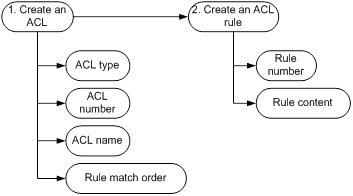
ACL configuration entails the creation of ACLs and creation of ACL rules.
· Configure the ACL type, number, name when creating an ACL.
· Configure the rule number and content when creating an ACL rule.
Figure 1 ACL configuration process
The following is an ACL configuration example:
#
acl number 3001
rule 5 permit ip source 10.0.0.1 0
rule 10 deny ip destination 20.0.0.1 0
rule 15 deny igmp
rule 20 deny udp destination-port eq tftp
rule 25 permit tcp source-port eq bgp
#
MQC
To make full use of ACLs, the switch supports using ACLs in the MQC to identify packets.
MQC overview
A Modular QoS Configuration (MQC) is a QoS policy. You can configure a QoS policy and then apply the QoS policy to a destination (for example, an interface). A QoS policy can contain traffic classes and their associated traffic behaviors. A traffic class classifies traffic, and a traffic behavior contains a set of QoS features (QoS actions) to take on the traffic class.
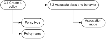
MQC configuration process
Figure 2 Class configuration process
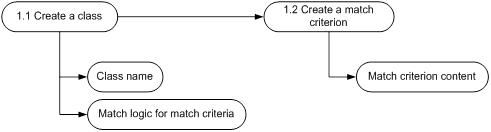
Figure 3 Behavior configuration process
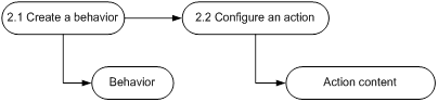
Figure 4 QoS policy configuration process
The following is an MQC configuration example:
#
acl number 3001
rule 5 permit ip source 10.0.0.1 0
#
traffic classifier c1 operator and
if-match acl 3001
#
traffic behavior b1
car cir 10240 cbs 640000 ebs 0 green pass red discard yellow pass
#
qos policy p1
classifier c1 behavior b1
#
The traffic class c1 uses ACL 3000 to classify packets.
The traffic behavior b1 uses a traffic policing action.
The QoS policy p1 associates traffic class c1 with traffic behavior b1.
The function of the MQC is to police traffic with source IP address 10.0.0.1.
Apply QoS policy p1 to the incoming packets of HundredGigE 5/0/1.
#
interface HundredGigE5/0/1
qos apply policy p1 inbound
#
ACL implementation
This section describes how configured ACL rules are stored in the device and how these rules are matched for packets.
TCAM
ACL rules are stored in TCAM. To help understand TCAM, we should first understand random access memory (RAM) and CAM.
Before TCAM and CAM appear, ACL rules are stored in RAM. In RAM, rules are searched in order until a match is found or all rules are searched.
Figure 5 Search method in RAM
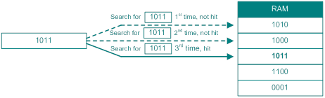
The search speed in RAM depends on the number of ACL rules. The more ACL rules, the lower the search speed. Content addressable memory (CAM) can improve the search speed.
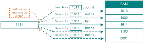
CAM bases searches on content. If a match is found, the address of the match is returned. The searches are in CAM performed all at once, thereby significantly improving the search speed.
Figure 6 Search method in CAM
Ternary Content Addressable Memory (TCAM) is an enhanced version of CAM and uses masks to search and match contents.
In RAM or CAM, each bit can only be in the '0' or '1' state. In TCAM, a bit can be in a third state 'don`t care'. This is what Ternary means: three states, which are implemented by using masks.
· Mask 1 means exact matching on data.
· Mask 0 means fuzzy matching on data. If the mask of a bit is 0, both 0 and 1 match the bit.
In Figure 7, crosses (X) represent bits with masks as 0.
Figure 7 Search method in TCAM
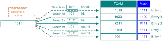
In Figure 7, 1011 is the search key to match the five entries in TCAM. If more than one entry is matched, the entry with the lowest entry ID (entry 1 in the figure) takes effect.
In conclusion, TCAM has the following benefits:
· Searches data based on content, and returns the address of the data if a match is found.
· Performs searches all at once at a high speed, independently of the number of rules.
Rule storage
After you configure an ACL or an MQC, and apply the configuration, the device stores rules in TCAM and stores traffic behaviors in static RAM (SRAM).
Figure 8 Rule storage in TCAM
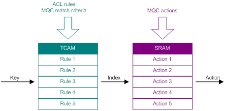
If more than one entry is matched, the entry with the lowest entry ID is selected and the associated action is taken. TCAM cannot meet the requirements of scenarios where multiple rules need to take effect.
For example, MQC p2 is applied to the incoming packets of HundredGigE 5/0/1 to police traffic with destination MAC address 6805-CA61-6987.
#
traffic classifier c2 operator and
if-match destination-mac 6805-CA61-6987
#
traffic behavior b2
car cir 10240 cbs 640000 ebs 0 green pass red discard yellow pass
#
qos policy p2
classifier c2 behavior b2
#
#
interface HundredGigE5/0/1
qos apply policy p2 inbound
#
At the same time, MQC p3 is applied to the incoming packets of VLAN 100 to count the packets with 802.1p priority 5.
#
traffic classifier c3 operator and
if-match service-dot1p 5
#
traffic behavior b3
accounting packet
#
qos policy p3
classifier c3 behavior b3
#
#
qos vlan-policy p3 vlan 100 inbound
#
If a packet with destination MAC address 6805-CA61-6987, VLAN ID 5, and 802.1p priority 5 is received on HundredGigE 5/0/1, the packet needs to match both MQCs. To support this scenario, TCAM is divided into small logical units, called slices.
Figure 9 Slices
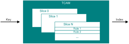
In each slice, one rule can be hit. Multiple slices can be searched at the same time for one packet.
If multiple slices are hit, all associated actions take effect if they do not conflict. If conflicts exist, the action with a higher priority takes effect.
Key
The information a device uses to perform a TCAM lookup is called a key. For example, 1011 in "TCAM" is a key.
A key is constructed by the copy engine (CE) based on fields in packet headers. The CE is a type of hardware resources in the forwarding chip used to extract packet information.
For an ACL rule used to match the destination MAC address, source MAC address, destination IP address, and source IP address, the forwarding chip will extract these fields from the packet and construct a key, as shown in Figure 10.
Figure 10 Key construction process
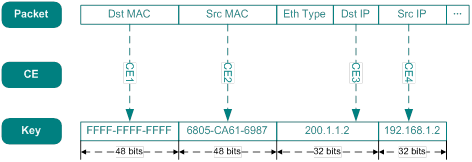
Note that the forwarding chip uses different CE resources (16-bit and 32-bit) when extracting different fields. The forwarding chip might combine multiple CE resources to extract a large-width field.
A MAC address is 48 bits long, so CE 1 and CE 2 each is composed of one 16-bit CE resource and one 32-bit CE resource. An IP address is 32 bits long, so CE 3 and CE 4 each is composed of one 32-bit CE resource.
Different ACL rules require different CE resources and generate different keys. Therefore, the numbers of CE resources and key resources in hardware determine the number of ACL rules that can be configured.
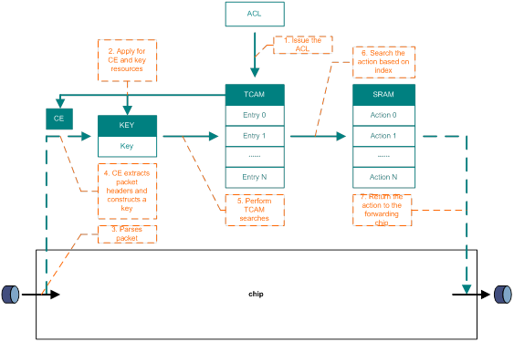
ACL search process
The ACL search process is as follows:
1. The user configures an ACL rule, which is issued to the TCAM.
a. The TCAM selects an ACL group for the ACL rule based on the rule content and stores the rule in the entry. If the ACL group cannot meet requirements, slices are connected.
b. The TCAM applies for CE resources and key resources based on the ACL group mode.
2. The forwarding chip parses the packet headers after the packet enters the device.
3. The CE extracts the packet fields and constructs a key.
4. The TCAM performs searches using the key.
5. The TCAM obtains the index of the hit entry.
6. The TCAM searches the action in SRAM associated with the entry.
7. The TCAM returns the action to the forwarding chip, which takes the action on the packet.
Figure 11 ACL search process
TCAM resource usage improvement on S12500X-AF
The switch improves TCAM resource usage in the following ways:
· Improves the usage of existing TCAM resources by using the methods described in "Application scenarios." These methods save QoS and ACL resources by using specific algorithms and require simple configuration.
· Increases the number of TCAM resources.
Use the hardware-resource tcam command to set the TCAM operating mode to allocate TCAM resources to the specified entries.
Support for the TCAM operating mode depends on the card type. For more information, see device management in H3C S12500X-AF Series Switch Fundamentals Configuration Guide.
Application scenarios
About the sharing mode and bulk interface configuration
If you apply a PBR policy or a packet filter to multiple interfaces on the same card, you can use the sharing mode or bulk interface configuration method to save TCAM resources. If you apply an MQC to multiple interfaces on the same card, you can use the sharing mode method to save TCAM resources.
If you apply the same configuration to different locations in sharing mode, the device uses one TCAM resource.
If you apply the same configuration to a contiguous range of VLAN interfaces (VLAN IDs), the device deploys the configuration to the VLAN interfaces by using the longest mask matching method. For example, if you apply the same configuration to VLAN interfaces 7 through 13, the device deploys the configuration to VLAN ID 7, VLAN IDs 8 to 11, and VLAN IDs 12 and 13. The device uses three TCAM resources instead of seven (one for VLAN 7, one for VLANs 8 to 11, and one for VLANs 12 and 13). The following table shows the calculation method:
VLAN ID (decimal) | VLAN ID (binary) | Mask | Configuration deployed to (VLAN/Mask) |
7 | 0111 | 1111 | 0111/1111 |
8 | 1000 | 1100 | 10XX/1100 |
9 | 1001 | 1100 | |
10 | 1010 | 1100 | |
11 | 1011 | 1100 | |
12 | 1100 | 1110 | 110X/1110 |
13 | 1101 | 1110 |
Configuration restriction and guidelines
The following restrictions apply to the sharing mode:
· For F series and H series cards:
¡ Four ACL groups are supported for Layer 2 and Layer 3 Ethernet interfaces.
¡ Three ACL groups are supported for VLAN interfaces and VSI interfaces.
· For F series and H series cards, seven ACL groups are supported.
| NOTE: One ACL group is occupied when you apply an ACL to multiple interfaces. |
· If a large number of ACL rules exist, it might take a long time to apply the ACL to the first interface or to remove the configuration from the last interface.
To save TCAM resources by using the sharing mode or bulk interface configuration, do not specify the counting keyword in any rules of the referenced ACL.
PBR
Sharing mode
About the sharing mode
You can use the sharing mode to save QoS and ACL resources when applying a PBR policy to multiple interfaces on the same card.
Procedure
· Common mode:
# Create VLANs. (Details not shown.)
# Create basic ACL 2001, and configure a rule to match packets with source IP address 10.0.0.1.
<Sysname> system-view
[Sysname] acl basic 2001
[Sysname-acl-ipv4-basic-2001] rule permit source 10.0.0.1 0
[Sysname-acl-ipv4-basic-2001] quit
# Configure Node 5 for the PBR policy a to forward matching packets to next hop 1.1.2.2.
[Sysname] policy-based-route a permit node 5
[Sysname-pbr-a-5] if-match acl 2001
[Sysname-pbr-a-5] apply next-hop 1.1.2.2
[Sysname-pbr-a-5] quit
# Configure interface PBR by applying the PBR policy aaa to VLAN-interface 8, VLAN-interface 9, VLAN-interface 10, and VLAN-interface 11 in common mode.
[Sysname] interface Vlan-interface 8
[Sysname-Vlan-interface8] ip policy-based-route a
[Sysname-Vlan-interface8] quit
[Sysname] interface Vlan-interface 9
[Sysname-Vlan-interface9] ip policy-based-route a
[Sysname-Vlan-interface9] quit
[Sysname] interface Vlan-interface 10
[Sysname-Vlan-interface10] ip policy-based-route a
[Sysname-Vlan-interface10] quit
[Sysname] interface Vlan-interface 11
[Sysname-Vlan-interface11] ip policy-based-route a
[Sysname-Vlan-interface11] quit
# Display QoS and ACL resource usage.
[Sysname] display qos-acl resource
Interfaces: HGE2/0/1 to HGE2/0/2, XGE2/0/3 to XGE2/0/50 (slot 2)
---------------------------------------------------------------------
Type Total Reserved Configured Remaining Usage
---------------------------------------------------------------------
VFP ACL 37632 0 0 37632 0%
IFP ACL 50176 8194 4 41978 16%
IFP Meter 30720 81 0 30639 0%
IFP Counter 8175 88 0 8087 1%
EFP ACL 18816 0 0 18816 0%
EFP Counter 4094 0 0 4094 0%
· Sharing mode:
# Configure VLANs, the ACL, PBR policy in the same way as in the common mode. (Details not shown.)
# Configure interface PBR by applying the PBR policy a to VLAN-interface 8, VLAN-interface 9, VLAN-interface 10, and VLAN-interface 11 in sharing mode.
<Sysname> system-view
[Sysname] interface Vlan-interface 8
[Sysname-Vlan-interface8] ip policy-based-route a share-mode
[Sysname-Vlan-interface8] quit
[Sysname] interface Vlan-interface 9
[Sysname-Vlan-interface9] ip policy-based-route a share-mode
[Sysname-Vlan-interface9] quit
[Sysname] interface Vlan-interface 10
[Sysname-Vlan-interface10] ip policy-based-route a share-mode
[Sysname-Vlan-interface10] quit
[Sysname] interface Vlan-interface 11
[Sysname-Vlan-interface11] ip policy-based-route a share-mode
[Sysname-Vlan-interface11] quit
# Display QoS and ACL resource usage.
[Sysname] display qos-acl resource
Interfaces: HGE2/0/1 to HGE2/0/2, XGE2/0/3 to XGE2/0/50 (slot 2)
---------------------------------------------------------------------
Type Total Reserved Configured Remaining Usage
---------------------------------------------------------------------
VFP ACL 37632 0 0 37632 0%
IFP ACL 50176 8194 1 41978 16%
IFP Meter 30720 81 0 30639 0%
IFP Counter 8175 88 0 8087 1%
EFP ACL 18816 0 0 18816 0%
EFP Counter 4094 0 0 4094 0%
Conclusion
In common mode, IFP ACL occupies four entries. Each VLAN interface applied with the same PBR policy occupies one QoS and ACL resource (one entry). In sharing mode, IFP ACL occupies one entries. All VLAN interfaces applied with the same PBR policy occupy one QoS and ACL resource (one entry).
In conclusion, each time the same policy is applied to a VLAN interface in common mode, one QoS and ACL resource is occupied. If the same policy is applied to multiple VLAN interfaces in sharing mode, only one QoS and ACL resource is occupied.
Bulk interface configuration
About bulk interface configuration
You can use the ip policy-based-route apply command to apply a policy to multiple VLAN interfaces at the same time to save QoS and ACL resources.
Procedure
· Apply a policy to multiple VLAN interfaces one by one:
# Configure VLANs, the ACL, PBR policy in the same way as in "Sharing mode." (Details not shown.)
# Configure interface PBR by applying the PBR policy a to VLAN-interface 8, VLAN-interface 9, VLAN-interface 10, and VLAN-interface 11 one by one.
<Sysname> system-view
[Sysname] interface Vlan-interface 8
[Sysname-Vlan-interface8] ip policy-based-route a
[Sysname-Vlan-interface8] quit
[Sysname] interface Vlan-interface 9
[Sysname-Vlan-interface9] ip policy-based-route a
[Sysname-Vlan-interface9] quit
[Sysname] interface Vlan-interface 10
[Sysname-Vlan-interface10] ip policy-based-route a
[Sysname-Vlan-interface10] quit
[Sysname] interface Vlan-interface 11
[Sysname-Vlan-interface11] ip policy-based-route a
[Sysname-Vlan-interface11] quit
# Display QoS and ACL resource usage.
[Sysname] display qos-acl resource
Interfaces: HGE2/0/1 to HGE2/0/2, XGE2/0/3 to XGE2/0/50 (slot 2)
---------------------------------------------------------------------
Type Total Reserved Configured Remaining Usage
---------------------------------------------------------------------
VFP ACL 37888 0 0 37888 0%
IFP ACL 50176 8192 4 41978 16%
IFP Meter 30720 40 0 30680 0%
IFP Counter 8175 48 0 8127 0%
EFP ACL 18944 0 0 18944 0%
EFP Counter 4094 0 0 4094 0%
· Apply a policy to multiple VLAN interfaces at the same time:
# Configure VLANs, the ACL, PBR policy in the same way as in "Sharing mode." (Details not shown.)
# Configure interface PBR by applying the PBR policy a to VLAN-interface 8, VLAN-interface 9, VLAN-interface 10, and VLAN-interface 11 at the same time.
<Sysname> system-view
[Sysname] ip policy-based-route a apply vlan-interface 8 9 10 11
# Display QoS and ACL resource usage.
[Sysname] display qos-acl resource
Interfaces: HGE2/0/1 to HGE2/0/2, XGE2/0/3 to XGE2/0/50 (slot 2)
---------------------------------------------------------------------
Type Total Reserved Configured Remaining Usage
---------------------------------------------------------------------
VFP ACL 37888 0 0 37888 0%
IFP ACL 50176 8192 1 41980 16%
IFP Meter 30720 40 0 30680 0%
IFP Counter 8175 48 0 8127 0%
EFP ACL 18944 0 0 18944 0%
EFP Counter 4094 0 0 4094 0%
Conclusion
In the first method, IFP ACL occupies four entries. In the second method, IFP ACL occupies one entry.
In conclusion, applying a policy to multiple VLAN interfaces at the same time saves QoS and ACL resources.
Packet filter
Sharing mode
About the sharing mode
You can use the sharing mode to save QoS and ACL resources when applying a packet filter to multiple interfaces on the same card.
Procedure
· Common mode:
# Create VLANs. (Details not shown.)
# Create basic ACL 2001, and configure a rule to match packets with source IP address 10.0.0.1, 192.168.1.1, or 200.0.0.2.
<Sysname> system-view
[Sysname] acl basic 2001
[Sysname-acl-ipv4-basic-2001] rule permit source 10.0.0.1 0
[Sysname-acl-ipv4-basic-2001] rule permit source 192.168.1.1 0
[Sysname-acl-ipv4-basic-2001] rule permit source 200.0.0.2 0
[Sysname-acl-ipv4-basic-2001] rule deny
[Sysname-acl-ipv4-basic-2001] quit
# Apply ACL 2001 to the incoming packets of VLAN-interface 8, VLAN-interface 9, VLAN-interface 10, and VLAN-interface 11 for packet filtering in common mode.
[Sysname] interface Vlan-interface 8
[Sysname-Vlan-interface8] packet-filter 2001 inbound
[Sysname-Vlan-interface8] quit
[Sysname] interface Vlan-interface 9
[Sysname-Vlan-interface9] packet-filter 2001 inbound
[Sysname-Vlan-interface9] quit
[Sysname] interface Vlan-interface 10
[Sysname-Vlan-interface10] packet-filter 2001 inbound
[Sysname-Vlan-interface10] quit
[Sysname] interface Vlan-interface 11
[Sysname-Vlan-interface11] packet-filter 2001 inbound
[Sysname-Vlan-interface11] quit
# Display QoS and ACL resource usage.
[Sysname] display qos-acl resource
Interfaces: HGE2/0/1 to HGE2/0/2, XGE2/0/3 to XGE2/0/50 (slot 2)
---------------------------------------------------------------------
Type Total Reserved Configured Remaining Usage
---------------------------------------------------------------------
VFP ACL 37632 0 0 37632 0%
IFP ACL 50176 8194 16 41978 16%
IFP Meter 30720 81 0 30639 0%
IFP Counter 8175 88 0 8087 1%
EFP ACL 18816 0 0 18816 0%
EFP Counter 4094 0 0 4094 0%
· Sharing mode:
# Configure VLANs and the ACL in the same way as in the common mode. (Details not shown.)
# Apply ACL 2001 to the incoming packets of VLAN-interface 8, VLAN-interface 9, VLAN-interface 10, and VLAN-interface 11 for packet filtering in sharing mode.
<Sysname> system-view
[Sysname] interface Vlan-interface 8
[Sysname-Vlan-interface8] packet-filter 2001 inbound share-mode
[Sysname-Vlan-interface8] quit
[Sysname] interface Vlan-interface 9
[Sysname-Vlan-interface9] packet-filter 2001 inbound share-mode
[Sysname-Vlan-interface9] quit
[Sysname] interface Vlan-interface 10
[Sysname-Vlan-interface10] packet-filter 2001 inbound share-mode
[Sysname-Vlan-interface10] quit
[Sysname] interface Vlan-interface 11
[Sysname-Vlan-interface11] packet-filter 2001 inbound share-mode
[Sysname-Vlan-interface11] quit
# Display QoS and ACL resource usage.
[Sysname] display qos-acl resource
Interfaces: HGE2/0/1 to HGE2/0/2, XGE2/0/3 to XGE2/0/50 (slot 2)
---------------------------------------------------------------------
Type Total Reserved Configured Remaining Usage
---------------------------------------------------------------------
VFP ACL 37632 0 0 37632 0%
IFP ACL 50176 8194 4 41978 16%
IFP Meter 30720 81 0 30639 0%
IFP Counter 8175 88 0 8087 1%
EFP ACL 18816 0 0 18816 0%
EFP Counter 4094 0 0 4094 0%
Conclusion
In common mode, IFP ACL occupies 16 entries. Each VLAN interface configured with the same packet filter occupies one QoS and ACL resource (four entries). In sharing mode, IFP ACL occupies four entries. All VLAN interfaces configured with the same packet filter occupy one QoS and ACL resource (four entries).
In conclusion, each time the same ACL is applied to a VLAN interface in common mode, one QoS and ACL resource is occupied. If the same ACL is applied to multiple VLAN interfaces in sharing mode, only one QoS and ACL resource is occupied.
Bulk interface configuration
About bulk interface configuration
You can use the packet-filter vlan-interface command apply an ACL to multiple VLAN interfaces at the same time to save QoS and ACL resources.
Procedure
· Apply an ACL to multiple VLAN interfaces one by one:
# Configure VLANs and the ACL in the same way as in "Sharing mode." (Details not shown.)
# Apply ACL 2001 to the incoming packets of VLAN-interface 8, VLAN-interface 9, VLAN-interface 10, and VLAN-interface 11 one by one for packet filtering.
<Sysname> system-view
[Sysname] interface Vlan-interface 8
[Sysname-Vlan-interface8] packet-filter 2001 inbound
[Sysname-Vlan-interface8] quit
[Sysname] interface Vlan-interface 9
[Sysname-Vlan-interface9] packet-filter 2001 inbound
[Sysname-Vlan-interface9] quit
[Sysname] interface Vlan-interface 10
[Sysname-Vlan-interface10] packet-filter 2001 inbound
[Sysname-Vlan-interface10] quit
[Sysname] interface Vlan-interface 11
[Sysname-Vlan-interface11] packet-filter 2001 inbound
[Sysname-Vlan-interface11] quit
# Display QoS and ACL resource usage.
[Sysname] display qos-acl resource
Interfaces: HGE2/0/1 to HGE2/0/2, XGE2/0/3 to XGE2/0/50 (slot 2)
---------------------------------------------------------------------
Type Total Reserved Configured Remaining Usage
---------------------------------------------------------------------
VFP ACL 37632 0 0 37632 0%
IFP ACL 50176 8194 16 41978 16%
IFP Meter 30720 81 0 30639 0%
IFP Counter 8175 88 0 8087 1%
EFP ACL 18816 0 0 18816 0%
EFP Counter 4094 0 0 4094 0%
· Apply an ACL to multiple VLAN interfaces at the same time:
# Configure VLANs and the ACL in the same way as in "Sharing mode." (Details not shown.)
# Apply an ACL to the incoming packets of VLAN-interface 8, VLAN-interface 9, VLAN-interface 10, and VLAN-interface 11 at the same time.
<Sysname> system-view
[Sysname] packet-filter 2001 vlan-interface 8 to 11 inbound
# Display QoS and ACL resource usage.
[Sysname] display qos-acl resource
Interfaces: HGE2/0/1 to HGE2/0/2, XGE2/0/3 to XGE2/0/50 (slot 2)
---------------------------------------------------------------------
Type Total Reserved Configured Remaining Usage
---------------------------------------------------------------------
VFP ACL 37888 0 0 37888 0%
IFP ACL 50176 8192 4 41976 16%
IFP Meter 30720 40 0 30680 0%
IFP Counter 8175 48 0 8127 0%
EFP ACL 18944 0 0 18944 0%
EFP Counter 4094 0 0 4094 0%
Conclusion
In the first method, IFP ACL occupies 16 entries. In the second method, IFP ACL occupies four entries.
In conclusion, applying an ACL to multiple VLAN interfaces at the same time saves QoS and ACL resources.
MQC
About the sharing mode
You can use the sharing mode to save QoS and ACL resources when applying an MQC to multiple interfaces on the same card.
Procedure
· Common mode:
# Create VLANs. (Details not shown.)
# Create a traffic class named c, and use VLAN ID 2 as the match criterion.
<Sysname> system-view
[Sysname] traffic classifier c
[Sysname-classifier-c] if-match service-vlan-id 2
[Sysname-classifier-c] quit
# Create a traffic behavior named b, and configure an action of mirroring packets to HundredGigE 2/0/1.
[Sysname] traffic behavior b
[Sysname-behavior-b] mirror-to interface hundredgige 2/0/1
[Sysname-behavior-b] quit
# Create a QoS policy named p, and associate traffic class c with traffic behavior b.
[Sysname] qos policy p
[Sysname-qospolicy-p] classifier c behavior b
[Sysname-qospolicy-p] quit
# Apply QoS policy p to the incoming packets of Ten-GigabitEthernet 2/0/3 in common mode.
[Sysname] interface ten-gigabitethernet 2/0/3
[Sysname-Ten-GigabitEthernet2/0/3] qos apply policy p inbound
[Sysname-Ten-GigabitEthernet2/0/3] quit
# Apply QoS policy p to the incoming packets of Ten-GigabitEthernet 2/0/4 in common mode.
[Sysname] interface ten-gigabitethernet 2/0/4
[Sysname-Ten-GigabitEthernet2/0/4] qos apply policy p inbound
[Sysname-Ten-GigabitEthernet2/0/4] quit
# Display QoS and ACL resource usage.
[Sysname] display qos-acl resource
Interfaces: HGE2/0/1 to HGE2/0/2, XGE2/0/3 to XGE2/0/50 (slot 2)
---------------------------------------------------------------------
Type Total Reserved Configured Remaining Usage
---------------------------------------------------------------------
VFP ACL 41984 0 0 41984 0%
IFP ACL 50176 8192 4 41984 16%
IFP Meter 30720 40 0 30680 0%
IFP Counter 8175 48 0 8127 0%
EFP ACL 20992 0 0 20992 0%
EFP Counter 4094 0 0 4094 0%
· Sharing mode:
# Configure the MQC in the same way as in the common mode. (Details not shown.)
# Apply QoS policy p to the incoming packets of Ten-GigabitEthernet 2/0/3 in sharing mode.
[Sysname] interface ten-gigabitethernet 2/0/3
[Sysname-Ten-GigabitEthernet2/0/3] qos apply policy p inbound share-mode
[Sysname-Ten-GigabitEthernet2/0/3] quit
# Apply QoS policy p to the incoming packets of Ten-GigabitEthernet 2/0/4 in sharing mode.
[Sysname] interface ten-gigabitethernet 2/0/4
[Sysname-Ten-GigabitEthernet2/0/4] qos apply policy p inbound share-mode
[Sysname-Ten-GigabitEthernet2/0/4] quit
# Display QoS and ACL resource usage.
[Sysname] display qos-acl resource
Interfaces: HGE2/0/1 to HGE2/0/2, XGE2/0/3 to XGE2/0/50 (slot 2)
---------------------------------------------------------------------
Type Total Reserved Configured Remaining Usage
---------------------------------------------------------------------
VFP ACL 41984 0 0 41984 0%
IFP ACL 50176 8192 2 41984 16%
IFP Meter 30720 40 0 30680 0%
IFP Counter 8175 48 0 8127 0%
EFP ACL 20992 0 0 20992 0%
EFP Counter 4094 0 0 4094 0%
Conclusion
In common mode, IFP ACL occupies four entries. Each VLAN interface applied with the same QoS policy occupies one QoS and ACL resource (two entries). In sharing mode, IFP ACL occupies two entries. All VLAN interfaces configured with the same QoS policy occupy one QoS and ACL resource (two entries).
If the traffic class used in an MQC occupies 100 entries and the MQC is applied to 100 VLAN interfaces in common mode, a total of 10000 (100*100) entries are occupied. If the MQC is applied to 100 VLAN interfaces in sharing mode, a total of 100 entries are occupied.
In conclusion, each time the same MQC is applied to a VLAN interface in common mode, one QoS and ACL resource is occupied. If the same MQC is applied to multiple VLAN interfaces in sharing mode, only one QoS and ACL resource is occupied.
References
· H3C S12500X-AF Series Switch ACL and QoS Configuration Guide
· H3C S12500X-AF Series Switch Fundamentals Configuration Guide
· H3C S12500X-AF Series Switch Layer 2—LAN Switching Configuration Guide
· H3C S12500X-AF Series Switch Layer 3—IP Routing Configuration Guide
