| Title | Size | Downloads |
|---|---|---|
| H3C SeerEngine-DC Troubleshooting Guide-E37xx-5W700-book.pdf | 525.11 KB |
- Table of Contents
- Related Documents
-
|
|
|
H3C SeerEngine-DC |
|
Troubleshooting Guide |
|
|
Document version: 5W700-20210702
Copyright © 2021 New H3C Technologies Co., Ltd. All rights reserved.
No part of this manual may be reproduced or transmitted in any form or by any means without prior written consent of New H3C Technologies Co., Ltd.
Except for the trademarks of New H3C Technologies Co., Ltd., any trademarks that may be mentioned in this document are the property of their respective owners.
The information in this document is subject to change without notice.
Contents
Collecting diagnostic log messages
Troubleshooting product licensing
Failure of a team to establish a connection to the license server
Member controller down after scaling out the controller from standalone mode to cluster mode
Inconsistent master controller role on the OpenFlow instance and a controller
Controller configuration failure in region creation or modification
Troubleshooting diagnostic information
Diagnostic information exporting failure on the active leader
NETCONF authentication failure
Long configuration deployment time via NETCONF
Troubleshooting basic networks
Physical device activation failure
VNF resource activation failure
Automatic region configuration failure
MAC address learning failure on the host connected to an access device
Failure to learn information about the host connected to an access device
Failure to activate an allowed address pair
Troubleshooting tenant networks
Communication failure between VMs
Communication failure between host and VSR gateway in underlay network
Communication failure between host and TOR gateway in underlay network
A gateway firewall is not in Active status
A gateway firewall in Active status does not take effect
A service chain firewall is not in Active status
A service chain firewall in Active status does not take effect
A policy or rule does not take effect
Troubleshooting load balancing
Service gateway-type load balancer state is not active
Virtual server state is not active
Server pool member state is not active
Gateway-type load balancer is active but does not take effect
Troubleshooting service chains
Service chain state is not active
A service chain is active but does not take effect
Troubleshooting security policies
OpenFlow entry deployment failure for a host
OpenFlow entry deployment failure for a network interface
Troubleshooting bare metal servers
Failure to update the inspection network mapping table for bare metal servers
Troubleshooting hierarchical ports
Failure of a VM created in OpenStack to come online on the SeerEngine-DC controller
Troubleshooting data center interconnects
Layer 3 traffic forwarding failure between data centers
Troubleshooting hybrid overlay
VM in host overlay cannot communicate with VM in network overlay
Two master nodes in a vBGP cluster
Abnormal vBGP instance session state
Troubleshooting module startup failures
Service module recovery failure after cluster restart
OVSDB communication failure between controller and host
Troubleshooting the IPv6 services
VM failure to obtain an IPv6 address
IPv6 address with a 128-bit prefix obtained through DHCPv6
Troubleshooting device setting anomalies
Flow or group entry anomaly on a vSwitch
Communication failure between VNFs of the host type within the same VPC
Failure to access the service address of a VNF of the BGP route type
RDRS setup failure because of network flapping
Abnormal site data synchronization and PXC cluster repairing failure
Component in primary state on both the primary and backup sites and service exceptions
Component in backup state on both the primary and backup sites and service exceptions
Component staying in syncing state for a long time rather than changing to synced
Introduction
This document provides information about troubleshooting common software and hardware problems with H3C SeerEngine-DC controllers.
General guidelines
To help identify the cause of the problem, collect system and configuration information (for failures related to devices, first identify whether the device preconfiguration is correct according to H3C SeerEngine-DC Device Preprovisioning Guide), including:
· SeerEngine-DC version, SNA Center version, and Matrix version.
· Symptom, time of failure, and configuration.
· Network topology information, including the network diagram, port connections, and points of failure.
· Log messages and diagnostic information. For more information, see "Collecting diagnostic log messages."
· Steps you have taken and their effects.
Collecting diagnostic log messages
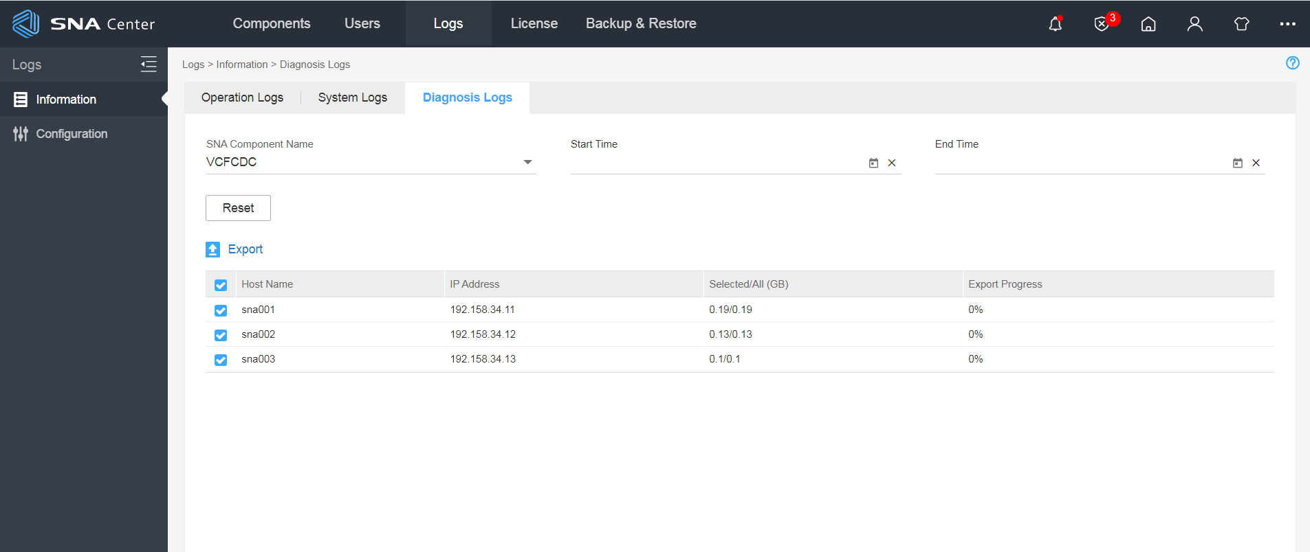
1. Enter the URL of the SNA Center GUI (in the format of http://SNA_Center_ip_address:10080/portal/) in the address bar of a browser to enter the SNA Center GUI login page.
2. On the login page, enter the username and password, and click Log In.
3. On the SNA Center GUI, access the Settings > Logs > Information > Diagnosis Logs page, as shown in Figure 1.
4. Select VCFCDC from the SNA component name list, and click Export.
|
|
NOTE: This operation will export the diagnostic logs of all three controllers. |
Contacting technical support
If you cannot resolve a problem after using the troubleshooting procedures in this document, contact H3C Support.
The following is the contact information for H3C Support:
· Telephone number—400-810-0504.
· E-mail—service@h3c.com.
Troubleshooting product licensing
This section provides troubleshooting information for common product licensing problems.
Failure of a team to establish a connection to the license server
Symptom
The controller team fails to establish a connection to the license server.
Solution
To resolve the problem:
1. Verify that the network between the controller and license server is operating properly.
2. Log in to the license server management page. On the License > Client Connection page, identify whether the user information is set up. If the user information has been set up, verify that the username and password are correct on the controller side.
3. If the problem persists, contact H3C Support.
Troubleshooting teams
This section provides troubleshooting information for common team problems.
Member controller down
Symptom
The state of a member controller is down.
Solution
To resolve the problem:
1. In the Controller Info area, check the Remarks field.
2. If the field displays The controller IP is unreachable or Connection timed out, the controller is down or the network is disconnected. To remove the problem, power cycle the controller, or repair the failed links to ensure network connectivity.
3. If the problem persists, contact H3C Support.
Member controller down after scaling out the controller from standalone mode to cluster mode
Symptom
After the controller is scaled out from standalone mode to cluster mode, if you delete and then add a member controller on the controller, the member controller state might be displayed as down.
Solution
If a member controller is deleted when the communication between the member controller and the leader controller fails, the data of the member controller might not be completely deleted. When the member controller is added again, its state might be displayed as down.
To resolve the problem:
1. On the page for editing the cluster, delete the specified member controller.
2. Log in to SNA Center. Click the System tab, and click the Settings icon.
3. From the navigation pane, select Components > Components.
4. Select the component to scale out, and click
the ![]() icon in the Actions column to enter the
page for scaling out the component.
icon in the Actions column to enter the
page for scaling out the component.
5. On the page that opens, delete the specified host.
6. Select the host on which you want to install the component, select the uplink interfaces to bind to the networks on the host, and click OK.
7. Review the scale-out settings, and then click OK.
8. After the scale-out, log in to the controller. On the page for editing the cluster, click Add Controller, and add the member controller again.
Troubleshooting regions
This section provides troubleshooting information for common region problems.
Inconsistent master controller role on the OpenFlow instance and a controller
Symptom
When an OpenFlow instance is connected to multiple controllers in different regions, the master controller role is inconsistent on the OpenFlow instance and a controller.
Solution
To resolve the problem:
1. Verify that an OpenFlow instance is connected to only two controllers in a region.
When the OpenFlow instance is connected to a controller in a region, the controller issues its configured role (master or subordinate) to the OpenFlow instance. If the OpenFlow instance is then connected to the controllers in another region, the original master controller on the OpenFlow instance will be overwritten. For example, an OpenFlow instance is connected to controller A (master) and controller B (subordinate) in Region A. Then the OpenFlow instance is connected controller C (master) and Controller D (subordinate) in Region B. On the OpenFlow instance, controller C is the master and the other three are subordinates. However, controller A still determines that it is the master for the OpenFlow instance.
If the OpenFlow instance is connected to multiple controllers, delete unnecessary controllers specified on the OpenFlow instance. If the remaining two controllers are in different regions, you can modify the region configuration to assign the two controllers to the same region.
2. If the problem persists, contact H3C Support.
Controller configuration failure in region creation or modification
Symptom
The system prompts a controller configuration failure during region creation or modification.
Solution
To resolve the problem:
1. Verify that the controller is up and the network is connected.
a. Examine the Remarks field on the controller information page.
- If the field displays The controller IP is unreachable, the controller is down or the network is disconnected. Then go to step b.
- If the field does not display The controller IP is unreachable, go to step 2.
b. Power on or reinstall the controller, or troubleshoot the network failure.
2. If the problem persists, contact H3C Support.
Troubleshooting diagnostic information
This section provides troubleshooting information for common diagnostic information problems.
Diagnostic information exporting failure on the active leader
Symptom
Diagnostic information for some active controllers fails to be exported, or the exported file cannot be decompressed.
Solution
To resolve the problem, try to export diagnostic information for the target controllers by using the following methods:
· Export diagnostic information for the controllers on the SNA Center GUI:
a. On the SNA Center GUI, access the Settings > Logs > Information > Diagnosis Logs page.
b. Select VCFCDC from the SNA component name list, and click Export.
· Obtain the diagnostic information of a controller from the host server or VM of the controller:
a. Log in to the host server or VM of the controller through SSH.
a. Use a file transfer application (such as FTP) to download the diagnostic log file from the /opt/sdn/virgo/serviceability/logs directory of the controller docker.
Troubleshooting OpenFlow
This section provides troubleshooting information for common OpenFlow problems.
OpenFlow connection failure
Symptom
An OpenFlow connection is configured on an OpenFlow device. Access the Assurance > Controller Information page on the controller's GUI, and click the region for a controller in the Controller Info area. On the dialog box that opens, information about the device is not displayed.
Solution
To resolve the problem:
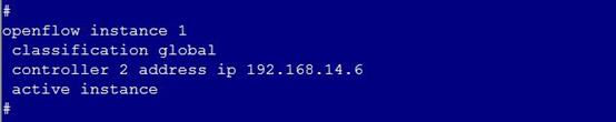
1. Log in to the OpenFlow device and verify that the controller IP address specified for the OpenFlow device is correct. If the controller IP address is incorrect, specify the correct controller IP address on the OpenFlow device as shown in Figure 2.
Figure 2 Specifying the controller IP address
2. Verify that the controller IP address is reachable. If the controller IP address is reachable, troubleshoot the network.
3. Verify that the OpenFlow device has established a connection to the controller by using the display openflow summary command.
Figure 3 Displaying OpenFlow connection channel state.
![]()
If channel status is not Connected, verify that the total number of OpenFlow connections established by the controller is not larger than the total number of nodes supported by the remote and local licenses. If the total number of OpenFlow connections established by the controller is larger than the total number of nodes supported by the remote and local licenses, update the remote or local license.
To view the total number of OpenFlow connections established by the controller, select Assurance > Controller Information on the controller's GUI.
To view the maximum number of nodes supported by the remote or local license, select System > License on the controller's GUI.
4. If the problem persists, contact H3C Support.
Unstable OpenFlow connection
Symptom
The OpenFlow connection established between the controller and the OpenFlow device is unstable.
Solution
To resolve the problem:
1. Verify that the network is connected. If the network is disconnected, troubleshoot the network.
2. Verify that traffic congestion does not occur in the region.
If traffic congestion occurs in the region, OpenFlow echo messages cannot be exchanged correctly. Execute the netstat -anp | grep 6633 command as a root user in the controller docker to identify whether the TCP channel for the OpenFlow connection is occupied. As shown in Figure 4, if the values for the first and the second columns are in the range of 200000 to 250000, the traffic in the region is heavy. You can disconnect OpenFlow connections for some OpenFlow devices and then connect these devices to controllers in other regions.

3. If the problem persists, contact H3C Support.
Flow entry deployment failure
Symptom
OpenFlow entries cannot be displayed on the OpenFlow device after the controller deploys flow entries to the OpenFlow device through REST API or the triggering of service packets.
Solution
To resolve the problem:
1. View the capability set of the OpenFlow device on the REST API /sdn/v2.0/of/datapaths/{dpid}/features/match. Verify that the capability set of the OpenFlow device supports the flow entries deployed by the controller. If the OpenFlow device does not support the flow entries, update the device or change a device.
2. Verify that the OpenFlow device supports identifying Experimenter extensions if the flow entries contain Experimenter extensions. If the OpenFlow device cannot identify Experimenter extensions, update the device or change a device.
3. Enable OpenFlow debugging by using the debugging openflow all command to verify that the OpenFlow device can receive FlowMod messages.
¡ If the device cannot receive FlowMod messages from the controller, verify that the connection between the OpenFlow device and the controller is Connected. For more information, see "Unstable OpenFlow connection."
¡ If the device can receive FlowMod messages from the controller, go to step 4.
4. If the problem persists, contact H3C Support.
Troubleshooting NETCONF
This section provides troubleshooting information for common NETCONF problems.
NETCONF communication failure
Symptom
The controller fails to use SOAP to issue NETCONF configuration. For example, after a device is added, its state is inactive and the system displays either of the following error messages:
· OpenFlow connection is down.
· NETCONF connection fails due to network congestion.
Solution
To resolve the problem:
1. Identify whether the physical device and the controller can ping each other by using the management IP of the physical device. If they cannot ping each other, troubleshoot the network. If they can ping each other, proceed with the following steps.
2. Verify that the NETCONF settings are consistent on the network device and the controller:
a. Make sure NETCONF over SSH is enabled on the network device.
b. Make sure the network device and the controller are configured with the same username and password.
If any inconsistency occurs, modify the NETCONF settings on the network device or the controller.
3. Verify that a NETCONF session can be established between the network device and the controller.
There is a limit on the number of NETCONF sessions that can be established on the network device. If the upper limit has been reached, the network device cannot establish a NETCONF session with the controller. In this case, delete the existing NETCONF sessions or increase the NETCONF session limit to ensure that a NETCONF session can be established between network device and the controller.
4. If the problem persists, contact H3C Support.
NETCONF authentication failure
Symptom
The state of a physical device is Inactive, with the prompt message that NETCONF connection failed.
Solution
To resolve the problem:
1. Verify that NETCONF over SSH is enabled on the network device.
2. Verify that the network device and the controller are configured with the same username and password.
3. If the problem persists, contact H3C Support.
Long configuration deployment time via NETCONF
Symptom
In the system log, the message that “The controller has waited more than 20 minutes for a response from NETCONF server 192.168.100.3. Request content:*****” is displayed. The message indicates that the controller fails to deploy configuration to the device through NETCONF and the device does not respond.
Solution
1. Identify whether the IP network between the device and the controller can reach each other at Layer 3. If the management network fails, troubleshoot the management network.
2. Verify that the CPU is not busy, the memory is sufficient, and no other exceptions exist on the device.
3. If the issue persists, contact H3C Support.
Troubleshooting basic networks
This section provides troubleshooting information for common basic network problems.
Physical device activation failure
Symptom
A physical device remains in inactive state after it is created.
Solution
To resolve the problem:
1. Verify the number of OpenFlow nodes and Overlay physical devices. If the number exceeds the limit allowed by the licenses, purchase new licenses.
2. Verify that the physical device and the controller can ping each other by using the management IP of the physical device. If the ping operation fails, troubleshoot the network connection problem.
3. If the physical device type is border device, verify that the physical device has joined a border device group.
4. Verify that NETCONF communication between the physical device and the controller succeeds. If NETCONF communication fails, troubleshoot NETCONF. For more information, see "Troubleshooting NETCONF."
5. Verify that a region is automatically selected for the physical device if the controller operates in team mode:
a. Select Provision > Inventory > Devices > Physical Devices.
b. View the status of the device.
- If the status is Inactive and the system prompts that the region is not activated or does not exist, troubleshoot automatic region configuration failure. For more information, see "Automatic region configuration failure."
- If other information is displayed, a region has been selected for the physical device. Go to the next step.
6. If the problem persists, contact H3C Support.
VNF resource activation failure
Symptom
A VNF resource remains in inactive state after it is created.
Solution
To resolve the problem:
1. Verify the number of OpenFlow nodes. If the number exceeds the limit allowed by the license, purchase a new license.
2. Verify that the VNF resource and the controller can ping each other by using the management IP of the VNF resource. If the ping operation fails, troubleshoot the network connection problem.
3. Verify that a region is automatically selected for the VNF resource if the controller operates in team mode:
a. Navigate to the Provision > Inventory > Devices > Virtual Devices page.
b. View the status of the device.
- If the status is Inactive and the system prompts that the region is not activated or does not exist, troubleshoot automatic region configuration failure. For more information, see "Automatic region configuration failure."
- If other information is displayed, a region has been selected for the physical device. Go to the next step.
4. If the problem persists, contact H3C Support.
Automatic region configuration failure
Symptom
A device fails to automatically select a region when the controller operates in team mode.
Solution
To resolve the problem:
1. Verify that a region is configured for the team:
a. Select System > Controller on the top navigation bar.
b. Click Region. If no region is configured, configure a region for the team.
2. Verify that the management IP address of the device belongs to the managed subnets of the configured region:
a. Select System > Controller on the top navigation bar.
b. Click Region.
c. Check the Managed Subnets field.
If the management IP address does not belong to the managed subnets, create a new region without any managed subnets, or perform the following tasks:
- Select System > Controller on the top navigation bar, and click Edit Region.
- In the Managed Subnets field, add the network segment of the management IP address.
3. If the problem persists, contact H3C Support.
Troubleshooting ARP
This section provides troubleshooting information for common ARP problems.
MAC address learning failure on the host connected to an access device
Symptom
When you perform a ping operation from a host connected to an access device, the host cannot learn the MAC address of the ping destination.
Solution
To resolve the problem:
1. Verify that the OpenFlow connections for the following pairs of devices have been successfully established:
¡ The controller and the access device that is connected to the source host.
¡ The controller and the access device that is connected to the ping destination.
2. Verify that the vPort information for both the source host and the ping destination is correctly configured on the controller. The vPort information includes IP address, MAC address, and the VLAN or VXLAN to which the source host or the ping destination belongs.
3. If the problem persists, contact H3C Support.
Failure to learn information about the host connected to an access device
Symptom
The host information cannot be obtained by the ARP module through REST API after the host that is connected to the access device starts.
Solution
To resolve the problem:
1. Verify that the physical device for the access device that is connected to the host is correctly configured on the controller.
2. Verify that the physical device is activated. If it is not activated, verify that the username and password for the physical device are correctly configured.
3. Verify that the physical device has flow entries to forward ARP packets to the controller. If the flow entries exist, perform a ping operation from the host to make the controller learn the host information.
4. If the problem persists, contact H3C Support.
Failure to activate an allowed address pair
Symptom
After you configure an allowed address pair for a VM with the access device as a vSwitch, the allowed address pair cannot be activated. The gateway does not receive ARP entries for the IP address from the controller.
Solution
To resolve the problem:
1. Verify that the vPort corresponding to the VM is up.
2. Identify whether the vSwitch hosting the vPort has the ARP entry corresponding to the IP address and destined to the controller and whether the IP address exists on the vSwitch.
¡ If they both exist, use this IP address as the source IP address to ping another VM from the current vSwitch to trigger sending ARP packets to the controller to activate the IP address.
¡ If the ARP entry and the IP address do not exist, proceed with the next step.
3. Verify that the IP address in the allowed address pair does not conflict with that of the vSwitch.
4. If the problem persists, contact H3C Support.
Troubleshooting tenant networks
This section provides troubleshooting information for common tenant network problems.
Communication failure between VMs
Symptom
Two VMs cannot communicate with each other.
Solution
To resolve the problem:
1. Verify that the vPorts and the uplink interfaces of both VMs are in up state, and the networks to which the two VMs belong are of the same type.
2. Verify that the subnets to which the two VMs belong are bound to the same vRouter.
3. Verify that the VMs have relevant ARP entries. If the VMs do not have relevant ARP entries, verify that the hosts of the VMs have connected to the controller.
4. Verify that the ARP entries are correct. If the ARP entries are incorrect, delete the incorrect ARP entries.
5. Verify that the hosts of the two VMs can ping the VTEP IP address of each other. If the hosts of the two VMs cannot ping the VTEP IP address of each other, delete the host and then add the host on the controller.
6. Verify that the two VMs are configured with security policies to permit the IP address of each other.
7. Navigate to the Provision > Network Design > Domains > Hosts page.
8. Click the Details link in the Data Sync State column for the host to enter the data synchronization details page for the host.
9. Audit the configuration to identify whether the flow entries on the controller are consistent with those on the host of the VM.
¡ If not, synchronize the data to make the flow entries consistent on the controller and the host.
¡ If yes, proceed with the next step.
10. If the problem persists, contact H3C Support.
Communication failure between host and VSR gateway in underlay network
Symptom
The host cannot use the VTEP IP address to communicate with the VSR gateway in the underlay network.
Solution
To resolve the problem:
1. Verify that the VTEP IP address and the IP address of the VSR gateway belong to different networks.
If they belong to the same network, perform either task:
¡ For a CAS domain, configure the VTEP IP address on the vSwitch to make sure it does not belong to the same network as the IP address of the VSR gateway.
¡ For a KVM domain, configure the VTEP IP address on the compute node to make sure it does not belong to the same network as the IP address of the VSR gateway.
2. If the problem persists, contact H3C Support.
Communication failure between host and TOR gateway in underlay network
Symptom
The host cannot use the VTEP IP address to communicate with the TOR gateway in the underlay network.
Solution
To resolve the problem:
1. Verify that the next hop of the default route is the IP address of the TOR gateway. If the next hop of the default route is not the IP address of the TOR gateway, configure the IP address of the TOR gateway as the next hop of the default route.
2. If the problem persists, contact H3C Support.
Troubleshooting firewalls
This section provides troubleshooting information for common firewall problems.
A gateway firewall is not in Active status
Symptom
A gateway firewall is not in Active status after it is successfully created.
Solution
To resolve the problem:
1. Verify that the firewall is bound to a vRouter.
Navigate to the Tenants > Services > Firewall > Firewall > Edit Firewall page. Identify whether the firewall is bound to a vRouter.
¡ If the firewall is not bound to a vRouter, modify the firewall configuration and bind it to a vRouter.
¡ If the firewall is bound to a vRouter, go to the next step.
2. If the problem persists, contact H3C Support.
A gateway firewall in Active status does not take effect
Symptom
A gateway firewall is in Active status but does not take effect after it is successfully created.
Solution
To resolve the problem:
1. Verify that an external network is bound to the vRouter.
Navigate to the Tenants > Your Network > Virtual Router page. Identify whether the External Network column for the vRouter displays None. If yes, you must create an external network and bind it to the vRouter. To create an external network, navigate to the Tenants > Common Network Settings > External Networks page.
2. Verify that the external network contains a subnet.
Navigate to the Tenants > Common Network Settings > External Networks page. Identify whether Subnets (0) is displayed in the Subnet Information column for the external network.
¡ If yes, create a subnet.
¡ If not, go to the next step.
3. Verify that the vRouter is bound to a gateway.
Navigate to the Tenants > Your Network > Virtual Router page. In the Gateway Resources column, identify whether the vRouter is bound to a gateway.
¡ If not, modify the vRouter configuration and bind it to a gateway.
¡ If yes, go to the next step.
4. Verify that a subnet interface is bound to the vRouter.
Navigate to the Tenants > Your Network > Virtual Router page. Identify whether Interfaces (0) is displayed in the Interfaces/Subnets column for the vRouter.
¡ If yes, modify the vRouter configuration and add interfaces to the vRouter.
¡ If not, go to the next step.
5. Verify that an OpenFlow connection is established between the gateway and the controller.
a. Navigate to the Tenants > Common Network Settings > Gateway page. Identify the tenant of the vRouter corresponding to the gateway firewall. Click the gateway member to determine the device group.
b. Navigate to the Provision > Inventory > Devices > Border Device Groups page. Query member devices in the device group.
c. Navigate to the Provision > Inventory > Devices > Physical Devices page. Identify whether OpenFlow connections are established between the controller and the group member devices.
d. If no OpenFlow connection is established, see "OpenFlow connection failure." If an OpenFlow connection is established, go the next step.
6. Verify that the gateway exists in a region.
Navigate to the Assurance > Controller Information page. Click the region in the Controller Info area to view the region details and verify that the gateway belongs to a region. If the gateway does not belong to a region, verify that a region has been created.
¡ If no region is created, create a region first.
¡ If a region has been created, go to the next step.
7. If the problem persists, contact H3C support.
A service chain firewall is not in Active status
Symptom
A service chain firewall is not in Active status after it is successfully created.
Solution
To resolve the problem:
1. Verify that the firewall is bound to a vFW resource.
Navigate to the Tenants > Services > Firewall > Firewall page. Identify whether Resources (0) is displayed in the Security Zones/Resources column. If yes, create a resource and bind the firewall to the resource.
2. Verify that the firewall is being used by a service chain.
Navigate to the Tenants > Services > Service Chain > Service Chain page. Click the Edit icon in the Actions column to identify whether the service chain is using the firewall. If no service chain is using the firewall, modify the service chain configuration and drag the corresponding firewall service instance to the service chain in the block diagram, and click Apply in the upper right corner.
3. If the problem persists, contact H3C Support.
A service chain firewall in Active status does not take effect
Symptom
A service chain firewall is in Active status but does not take effect after it is successfully created.
Solution
To resolve the problem:
1. Verify that an OpenFlow connection is established between the vFW resource and the controller.
a. Navigate to the Tenants > Services > Firewall > Firewall page. Click the Resources link for the service chain firewall. Query the vFW resource bound to the service chain firewall.
b. Navigate to the Provision > Inventory > Devices > Virtual Devices page. Identify whether the vFW resource is active. If yes, an OpenFlow connection has been established between the vFW and the controller.
c. If no OpenFlow connection is established, see "OpenFlow connection failure." If an OpenFlow connection is established, perform the following tasks:
2. If the problem persists, contact H3C support.
A policy or rule does not take effect
Symptom
A policy or rule is added or modified for a firewall. However, the policy or rule does not take effect.
Solution
To resolve the policy failure:
1. Verify that the Activate option is selected for the policy.
Navigate to the Tenants > Services > Firewall > Security Policy page and click the Policy tab. Identify whether the Activate Status column for the policy displays a green icon. If not, edit the policy and select the Activate option.
2. If the problem persists, contact H3C Support.
To resolve the rule failure:
1. Verify that the Activate option is selected for the rule.
Navigate to the Tenants > Services > Firewall > Security Policy page and click the Rule tab. If the Activate Status column for the rule displays False, modify the rule and select the Activate option.
2. If the problem persists, contact H3C Support.
Troubleshooting load balancing
This section provides troubleshooting information for common load balancing problems.
Service gateway-type load balancer state is not active
Symptom
A service gateway-type load balancer remains in inactive state after it is created.
Solution
To resolve the problem:
1. On the Tenants > Services > Load Balancing > Load Balancer page, identify whether the listener field displays --- for the load balancer. If yes, click Edit for the load balancer in the Actions column, and add a listener on the dialog box that opens. If not, go to the next step.
2. On the Tenants > Services > Load Balancing > VIP page, identify whether the virtual server is active. If yes, perform tasks in "Virtual server state is not active." If not, go to the next step.
3. If the problem persists, contact H3C Support.
Virtual server state is not active
Symptom
A virtual server remains in inactive state after it is created.
Solution
To resolve the problem:
1. On the Tenants > Your Network > Virtual Router page, click the Edit icon for the vRouter, and identify whether the virtual subnet bound to the server pool has been added to the vRouter. If the virtual subnet is not added to the vRouter, click Add on the Interfaces/Subnets tab, and add the virtual subnet to the vRouter.
2. On the Tenants > Your Network > Virtual Router page, view the Gateway Resources column to identify whether the vRouter has been bound to a gateway. If not, bind a gateway to the vRouter. If yes, go to the next step.
3. On the Tenants > Your Network > Virtual Router page, identify whether the External Networks column displays None. If yes, bind an external network to the vRouter (to create an external network, access the Tenants > Common Network Settings > External Network page).
4. If the problem persists, contact H3C Support.
Empty server pool member list
Symptom
The member list is empty for a server pool when a member is added.
Solution
To resolve the problem:
1. On the Tenants > Services > Load Balancing > Virtual Port page, identify whether the vSubnet of the server pool member has vPorts. If not, configure vPorts. If yes, go to the next step.
2. If the problem persists, contact H3C Support.
Server pool member state is not active
Symptom
A server pool member remains in inactive state after it is created.
Solution
To resolve the problem:
1. Access the Tenants > Services > Load Balancing > Listener page. Click the Edit icon for the listener and identify whether the listener has referenced a correct server pool. If not, edit the configuration. If yes, go to the next step.
2. If the problem persists, contact H3C Support.
Gateway-type load balancer is active but does not take effect
Symptom
The gateway-type load balancer is active but does not take effect.
Solution
To resolve the problem:
1. Verify that an OpenFlow connection is established between the gateway and the controller.
a. Navigate to the Tenants > Tenant Management > All Tenants page. Select the tenant to which the load balancer belongs, and click Edit for the tenant to identify the border gateway bound to the tenant.
b. Navigate to the Tenants > Common Network Settings > Gateway page. Query the device group to which the gateway member of the vRouter's tenant belongs.
c. Navigate to the Provision > Inventory > Devices > Border Device Groups page. Query member devices in the device group.
d. Navigate to the Provision > Inventory > Devices > Physical Devices page. Identify whether the online state of the device is active. If yes, OpenFlow connections are established between the controller and the group member devices.
e. If no OpenFlow connection is established, see "OpenFlow connection failure." If an OpenFlow connection is established, go to the next step.
2. Verify that the management IP address of the device belongs to the managed subnets of the configured region:
a. Select System > Controller on the top navigation bar.
b. Click Region.
c. Check the Managed Subnets field.
If the management IP address does not belong to the managed subnets, create a new region without any managed subnets, or perform the following tasks:
- Select System > Controller on the top navigation bar, and click Edit Region.
- In the Managed Subnets field, add the network segment of the management IP address.
3. If the problem persists, contact H3C Support.
Troubleshooting service chains
This section provides troubleshooting information for common service chain problems.
Service chain state is not active
Symptom
After a service chain is created, its state is not Active.
Solution
To resolve the problem:
1. Verify that all service instances for the service chain are bound to resources. If any service instance is not bound to a resource, modify the service instance configuration.
2. If the problem persists, contact H3C Support.
A service chain is active but does not take effect
Symptom
A service chain is active but does not take effect.
Solution
To resolve the problem:
1. Verify that the source and destination contexts of the service chain match the source and destination addresses of the traffic. If they do not match, modify the source and destination contexts of the service chain.
2. Verify that the service instances of the service chain operate correctly. If they do not operate correctly, see the service instance troubleshooting guide.
3. Identify whether the configuration is properly deployed to each device on the service chain path. If not, verify that the configuration deployment is correct. If not, go to the next step.
4. If the problem persists, contact H3C Support.
Troubleshooting security policies
This section provides troubleshooting information for common security policy problems.
OpenFlow entry deployment failure for a host
Symptom
The controller cannot deploy a security policy OpenFlow entry for a host after the host comes online.
Solution
To resolve the problem:
1. Verify that an OpenFlow connection is established between the OpenFlow device that the host is connected to and the controller. If no OpenFlow connection exists, see "OpenFlow connection failure."
2. Verify that the user group and security policy are correctly configured. If the configuration is incorrect, modify the configuration.
3. If the problem persists, contact the H3C Support.
OpenFlow entry deployment failure for a network interface
Symptom
The network interfaces between OpenFlow devices are in up state, but the controller cannot deploy network interface OpenFlow entries.
|
|
NOTE: The network interface OpenFlow entries ensure that the packets that trigger host learning, such as ARP learning, are not forwarded to the controller. |
Solution
To resolve the problem:
1. Verify that an OpenFlow connection is established between the OpenFlow device that hosts are connected to and the controller. If no OpenFlow connection exists, see "OpenFlow connection failure."
2. Verify that the OpenFlow device is correctly configured. If the configuration is incorrect, modify the configuration.
3. Access the System > Parameters page. In the Link area, verify that the learn.multihop.links parameter is set to true.
4. Access the System > Parameters page. In the Link area, verify that the timeout.links parameter is set to true.
5. If the problem persists, contact the H3C Support.
Troubleshooting bare metal servers
This section provides troubleshooting information for common bare metal server problems.
Failure to update the inspection network mapping table for bare metal servers
Symptom
When an interface is bound to or unbound from the inspection network mapping table of a bare metal server, the operation fails and the system prompts an internal error. In the operation log, the failure cause is "Internal server error."
Solution
To resolve the problem:
1. Navigate to the Provision > Network Design > BM Server page, and click the Access Network tab. Click the Edit icon in the Apply to Interfaces area for the inspection network mapping table, and record all devices and interfaces bound to the inspection network mapping table. Navigate to the Provision > Inventory > VNID Pools > VLAN-VXLAN Mappings page, and click the Interfaces link in the Apply to Interfaces area for the inspection network mapping table, and record all devices and interfaces bound to the inspection network mapping table.
2. Compare the records on the two pages. Record the interfaces that exist on the BM Server page but do not exist on the VLAN-VXLAN Mappings page, and remove these interfaces on the BM Server page.
3. Log in to the device. Execute the vtep access port command on the removed interfaces. (If an interface has been assigned to an aggregate interface, first remove the interface from the aggregate interface and then execute the vtep access port command.) Then, bind the interfaces to the inspection network mapping table on the BM Server page.
4. Verify that interfaces on the BM Server page are the same as interfaces on the VLAN-VXLAN Mappings page.
5. If the problem persists, contact the H3C Support.
Troubleshooting hierarchical ports
This section provides troubleshooting information for common hierarchical port problems.
Failure of a VM created in OpenStack to come online on the SeerEngine-DC controller
Symptom
In the hierarchical port binding scenario, a VM created in OpenStack is normal. However, the VM fails to obtain an IP address, and fails to come online on the SeerEngine-DC controller.
Solution
To resolve the problem:
1. On the compute node, capture packets of the interface connected to the S6800 switch. Identify whether the interface can properly send LLDP packets. If not, enable LLDP or re-enable LLDP on the compute node. If not, go to the next step.
2. Log in to the SeerEngine-DC controller. Navigate to the Provision > Fabrics page. Identify whether sending LLDP packets to the controller and sending DHCP packets to the controller are enabled for the fabric of the VDS for connecting the SeerEngine-DC controller to OpenStack. If not, enable these functions. If yes, go to the next step.
3. Log in to OpenStack. Navigate to the Project > Compute > Access & Security page. Click Manage Rules for the specified security group. Identify whether the security group bound to the VM is configured with the rule to permit the gateway IP in the ingress direction. If not, set the rule. If yes, go to the next step.
4. If the problem persists, contact the H3C Support.
Troubleshooting data center interconnects
This section provides troubleshooting information for data center interconnect problems.
Layer 3 traffic forwarding failure between data centers
Symptom
A Layer 3 data center interconnect has already between created between data centers, but Layer 3 traffic cannot be forwarded between these data centers.
Solution
To resolve the problem:
1. Identify whether the border devices support L3VNI matching and modification in PBR. If not, replace the devices.
2. Verify that the Layer 3 data center interconnects configured on controllers in these data centers are mapped to the same segment ID.
3. Verify that the import RTs and export RTs of the Layer 3 data center interconnects configured on controllers in these centers match.
4. If the problem persists, contact the H3C Support.
Troubleshooting M-LAG
This section provides troubleshooting information for common M-LAG problems.
VMs on the local DR interface come online and are assigned configuration, but VMs on the peer DR interface are not assigned backup configuration
Symptom
Two devices in the same DR system have been activated. VMs on the DR interface of one device come online and are assigned the VSI and AC configuration. However, the VMs on the DR interface of the peer device in the same DR system are not assigned the corresponding VSI and AC configuration.
Solution
To resolve the problem:
1. Verify that the DR interfaces in the same DR system are bound to the same VLAN-VXLAN mapping table.
2. Verify that the vtep access port command is executed on the peer DR interface.
3. If the problem persists, contact the H3C Support.
Troubleshooting hybrid overlay
This section provides troubleshooting information for common hybrid overlay problems.
VM in host overlay cannot communicate with VM in network overlay
Symptom
The VM coming online in a host overlay cannot communicate with a VM coming online in a network overlay.
Solution
To resolve the problem:
1. Navigate to the Provision > Basic Service > BGP page. Click the BGP Clusters tab, and verify that the BGP cluster has been established.
2. Identify whether the BGP cluster status is up. If not, proceed with step 4. If yes, go to the next step.
3. Navigate to the Provision > Basic Service > BGP page. Click the BGP Instances tab, and verify that a BGP instance has been created.
4. If the problem persists, contact H3C Support.
Two master nodes in a vBGP cluster
Symptom
Both nodes in a vBGP cluster are master nodes. As a result, the routes cannot be advertised or received properly.
Solution
To resolve the problem:
1. Verify that:
¡ The server NIC is operating properly.
¡ The network cable is well connected.
¡ On the network segment of the two vBGP nodes, the Layer 2 switches communicate properly.
2. If the problem persists, contact H3C Support.
Abnormal vBGP instance session state
Symptom
The BGP session between a vBGP instance and its peer is in abnormal state.
Solution
To resolve the problem:
1. Verify that the peer information of the vBGP instance is correct.
2. If your network is an IPv6 network, verify that the router ID has been configured for the vBGP cluster.
3. Verify that the BGP settings on the peer device are correct.
4. Identify whether you can ping the vBGP cluster IP address from the peer device.
¡ If not, verify that the communication is proper in the underlay network.
¡ If yes, proceed with the next step.
5. If the problem persists, contact H3C Support.
Troubleshooting module startup failures
This section provides troubleshooting information for common module startup failure problems.
Service module recovery failure after cluster restart
Symptom
After the team is restarted, some service modules fail to recover.
Solution
The possible reason is that key system files are corrupted.
To resolve the problem, contact H3C Support.
Troubleshooting OVSDB
This section provides troubleshooting information for common OVSDB problems.
OVSDB communication failure between controller and host
Symptom
The OVSDB link between the SeerEngine-DC controller and a device fails. As a result, the related service is interrupted.
Solution
To resolve the problem:
1. Log in to the host. Execute the netstat -apn | grep 6632 command to identify the OVSDB port listening state. (If you have specified another port number, replace 6632 with the specified port number.)
¡ If the listening state of the port number is displayed, the listening port is normal. Proceed with the next step.
¡ If the listening state of the port number is not displayed, go to step 4.
2. Ping the host management IP address from each SeerEngine-DC controller.
¡ If the ping operation fails, proceed with the next step.
¡ If the ping operation succeeds, go to step 4.
3. Verify that the NICs and cables of the devices are operating properly. If a NIC or network cable fails, replace it and identify whether the alarm still exists after half a minute. If yes, proceed with the next step.
4. If the problem persists, collect the alarms, logs, and configuration, and contact H3C Support.
Troubleshooting the IPv6 services
This section provides troubleshooting information for common IPv6 service problems.
VM failure to obtain an IPv6 address
Symptom
After a VM is created, it fails to obtain an IPv6 address.
Solution
To resolve the problem:
1. Verify that the vPort corresponding to the vSwitch has been configured with an IPv6 address.
2. Navigate to the Provision > Network Design > Parameters > Controller Global Setting page. Identify whether IPv6 is enabled.
¡ If not, delete the existing IPv6-related settings, enable IPv6, and configure IPv6 settings again.
¡ If yes, proceed with the next step.
3. On the controller page, view the IPv6 subnet details. Verify that the subnet type is SLAAC, stateful DHCPv6, or stateless DHCPv6.
4. If the subnet type is stateful DHCPv6, restart the VM or execute the dhclient -6 -v command (the command varies by operating system) to force the VM to obtain an IP address again.
5. If the subnet type is SLAAC or stateless DHCPv6, identify whether the subnet has been bound to a vRouter.
¡ If not, bind the subnet to a vRouter. After binding, the controller will deploy RA-related settings to the device. Through RA messages, the VM can automatically configure the IP address.
¡ If yes, proceed with the next step.
6. If the problem persists, contact H3C Support.
IPv6 address with a 128-bit prefix obtained through DHCPv6
Symptom
The VM obtains an IPv6 address through DHCPv6. However, the IPv6 address has a 128-bit prefix, and cannot be used for communication with other VMs.
Solution
To resolve the problem:
1. On the controller page, view the IPv6 subnet details. Verify that the subnet type is stateful DHCPv6.
2. Identify whether the subnet has been bound to a vRouter.
¡ If not, bind the subnet to a vRouter. After binding, the controller will deploy RA-related settings to the device. Through RA messages, the VM can automatically obtain the network segment information.
¡ If yes, proceed with the next step.
3. If the problem persists, contact H3C Support.
Troubleshooting device setting anomalies
This section provides troubleshooting information for common device setting anomaly problems.
Flow or group entry anomaly on a vSwitch
Symptom
Some flow or group entries are missing or abnormal on a vSwitch.
Solution
To resolve the problem:
1. Log in to the controller.
2. Navigate to the Provision > Network Design > Domains > Hosts page.
3. Click the Details link in the Data Sync State column for the host to enter the data synchronization details page for the host.
4. Audit the configuration on this page.
5. Identify whether the flow or group entries on the controller are inconsistent with those on the host.
¡ If yes, click Sync Selected Data. Then, click Audit again to verify that the flow or group entries are the same on the controller and the host.
¡ If not, proceed with the next step.
6. If the problem persists, contact H3C Support.
Device configuration anomaly
Symptom
Some configurations are missing or abnormal on a device.
Solution
To resolve the problem:
1. Log in to the controller.
2. Navigate to the Provision > Inventory > Devices page.
3. Click the link in the Data Synchronization State column.
4. On this page, audit the configuration.
5. View the audit result. Identify whether different configurations exist on the device and the controller.
¡ If yes, verify that the different configurations are incorrect and click Data Sync to repair the differences. Then, audit the configurations again to verify that the configurations are the same on the controller and the device.
¡ If not, proceed with the next step.
6. If the problem persists, contact H3C Support.
Troubleshooting NFVI
This section provides troubleshooting information for common NFVI problems.
Communication failure between VNFs of the host type within the same VPC
Symptom
VNFs of the host type fail to communicate within the same VPC.
Solution
To resolve the problem:
1. View the details for the master vPort of the host-type VNF. Identify whether the VIP of the vPort is activated.
¡ If not, perform the tasks in “Failure to activate an allowed address pair.”
¡ If yes, proceed with the next step.
2. Log in to the controller.
3. Navigate to the Provision > Network Design > Domains > Hosts page.
4. Click the Details link in the Data Sync State column for the host to enter the data synchronization details page for the host.
5. On this page, audit the configuration. Identify whether the flow or group entries are inconsistent on the vSwitch (access switch of the host-type VNF) and the controller.
¡ If yes, perform the tasks in “Flow or group entry anomaly on a vSwitch.”
¡ If not, proceed with the next step.
6. If the problem persists, contact H3C Support.
BFD session anomaly
Symptom
Enable BFD to detect the next hop of a static route. The OpenFlow entry corresponding to the static route is not deployed, and the corresponding BFD session on the gateway is down. When multiple active gateways exist, the BFD session might be up on a gateway and down on other gateways.
Solution
To resolve the problem:
1. Verify that:
¡ The vPort and uplink interface of the VM corresponding to the next hop IP are up.
¡ The subnet of the VM has been bound to a vRouter.
¡ The MAC address of the VM is the same as the MAC address of the vPort on the controller.
¡ IP-MAC anti-spoofing is disabled on the vPort of the VM.
2. Verify that the HA mode is set to multi-active for the border device group to which the gateway belongs and the border gateway group is configured with the VTEP IP address and border gateway MAC address.
3. Identify whether the source IP addresses of BFD packets conflict with the private network segment of the vRouter. If yes, plan the source IP addresses again, and make sure the number of configured source IP addresses is the same as the number of devices in the border device group to which the border gateway belongs.
4. Identify whether the host of the VM corresponding to the next hop IP and the gateway can ping the VTEP IP of each other.
¡ If not, troubleshoot the underlay network between the host and the gateway.
¡ If yes, proceed with the next step.
5. Identify whether the ARP entry corresponding to the next hop IP exists in the specified VPN on the gateway.
¡ If yes, verify that the IP and MAC in the ARP entry are the IP and MAC of the controller.
¡ If not, proceed with the next step.
6. If the problem persists, contact H3C Support.
Failure to access the service address of a VNF of the BGP route type
Symptom
Failed to access the service address of a VNF of the BGP route type.
Solution
To resolve the problem:
1. In the routing table referenced by the vRouter of the BGP route-type VNF, identify whether a static route is configured with the next hop as the IP address of the vPort corresponding to the VNF.
¡ If not, configure such a static route through the cloud platform or controller.
¡ If yes, proceed with the next step.
2. Identify whether a BGP peer is configured for the BGP route-type VNF in the BGP peer list on the controller.
¡ If not, configure the BGP peer through the cloud platform or controller.
¡ If yes, proceed with the next step.
3. Log in to the controller.
4. Navigate to the Provision > Network Design > Domains > Hosts page.
5. Click the Details icon in the Actions column for the host to enter the data synchronization details page for the host.
6. On this page, audit the configuration. Identify whether the flow or group entries are inconsistent on the vSwitch (access switch of the VNF) and the controller.
¡ If yes, perform the tasks in “Flow or group entry anomaly on a vSwitch.”
¡ If not, proceed with the next step.
7. Log in to the controller.
8. Navigate to the Provision > Inventory > Devices page.
9. Click the Details link the Data Sync State column for the device to enter the data synchronization details page for the device.
10. On this page, audit the configuration. Identify whether incorrect configurations exist on the device.
¡ If yes, perform tasks in “Device configuration anomaly.”
¡ If not, proceed with the next step.
11. Identify whether the BFD session corresponding to the route entry in step 1 is normal.
¡ If not, perform tasks in “BFD session anomaly.”
¡ If yes, proceed with the next step.
12. If the problem persists, contact H3C Support.
Troubleshooting RDRS
This section provides troubleshooting information for common RDRS problems.
RDRS setup failure because of network flapping
Symptom
The state of the network between the primary and the backup sites is abnormal. As a result, the RDRS fails to be set up, and the RDRS functions of the backup site are unavailable.
Solution
To resolve the problem:
1. Restore the communication between the primary and the backup sites.
[root@node1 ~]# cd /opt/matrix/app/install/metadata/VCFCDC/rdr/rdr/scripts
[root@node1 scripts]# ./rdrMemberRecovery.sh
3. After the script is executed, log in to SNA Center deployed on the backup site. If you can browse the backup site page normally, the system is restored.
4. If the problem persists, contact H3C Support.
Abnormal site data synchronization and PXC cluster repairing failure
Symptom
After the network between the primary site and the backup site is disconnected and then connected, the data synchronization state of the component is displayed as abnormal, and the system log prompts that repairing the PXC cluster failed.
Solution
1. Log in to the SNA Center server for the primary site. Enter the following commands to enter the directory of the repairing scripts and execute the restoration script.
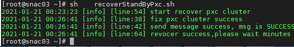
[root@node1 ~]# sh /opt/matrix/app/install/metadata/VCFCDC/rdr/rdr/scripts/recoverStandByPxc.sh
2. If the execution result is as shown in Figure 2, the restoration succeeded. Wait a few minutes, and log in to the primary site to identify whether the data synchronization state of the component is restored to normal.
Figure 5 Restored PXC cluster successfully
3. If the problem persists, contact H3C Support.
Component in primary state on both the primary and backup sites and service exceptions
Symptom
A component is in primary state on both the primary and backup sites. The southbound IP addresses of the component conflict, which causes service exceptions. Log in to SNA Center deployed on the primary and backup sites separately. You can access the Application-Driven DataCenter page on both the primary and backup sites.
Solution
Possible reasons include:
· When the switchover mode of the RDRS is set to Auto Switchover with Arbitration, the RDRS microservice has exceptions on the site where the primary component resides. As a result, the arbitration service automatically switches the component to the primary state on the backup site, and the component is still in primary state on the previous primary site. Because the RDRS microservice has exceptions on the primary site, the component on the previous primary site cannot be switched to the backup state. Consequently, the component is in primary state on both the primary and backup sites.
To resolve the problem:
1. Remotely log in to the SNA Center server for the primary site.
2. Execute the kubectl get pod -n base-service | grep rdr command to identify whether the RDRS is running properly.
¡ If the command output is as shown in Figure 3, the failure reason might be reason 2 or 3 mentioned above. In this case, perform the following tasks:
- From the primary and backup sites, select a site on which you want to switch the component to the backup state.
- Log in to the RDRS page on the site, and click the ![]() icon for the
component to switch the component to the backup state.
icon for the
component to switch the component to the backup state.
- Wait the component to switch to the backup state.
You can determine that the problem is resolved when the following conditions exist:
- The component state changes to Backup on the RDRS page.
- The data sync state changes to Synced.
- You cannot log in to the Application-Driven DataCenter page on the site.
In this case, you do not need to perform the following tasks.
¡ If you cannot search for the RDRS or the RDRS is not in Running state as shown in Figure 3 and you can log in to the Application-Driven DataCenter page from SNA Center on both the primary and backup sites, the problem still exists. Proceed with step 3 to resolve this problem.
Figure 6 RDRS running properly
![]()
3. Log in to the servers of all master nodes in SNA Center for the primary site, perform the following tasks to resolve this problem:
a. Enter the path of scripts.
[root@node1 ~]# cd /opt/matrix/app/install/metadata/VCFCDC/scripts/
b. Execute the restoration script to switch the primary site to the backup site.
[root@node1 scripts]# ./disasterRecoveryMasterToSlavePre.sh
c. Execute a script to restore the RDRS configuration. For example, on primary node node1.
- Log in to SNA Center for the backup site to view the RDRS network IP address on node1. Click the System tab, and click the Settings icon.
- On the component page, click the ![]() icon for the DC
component in the Actions column.
icon for the DC
component in the Actions column.
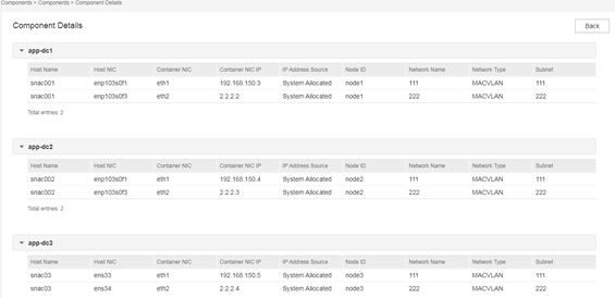
- On the component details page as shown in the following figure, view the IP address of NIC eth2 (2.2.2.2 in this example) in the container of node1.
- Log in to the SNA Center for the primary site. Execute the following command, in which the IP address is the RDRS network IP address of node1 of the backup site.
[root@node1 scripts]# /disasterRecoveryMasterToSlavePost.sh 2.2.2.2
d. After the script is executed, try to access the Application-Driven DataCenter page from SNA Center for the primary site. You can determine that the problem is resolved if you cannot access the page, the primary site is successfully switched to the backup state.
4. According to the search result in step 2, perform one of the following tasks:
¡ If no RDRS is searched in step 2, log in to the server of any master node in the previous primary site, and execute the following command:
[root@node1 ~]# kubectl apply -f /opt/matrix/app/install/metadata/VCFCDC/rdr/rdr/k8s-resources
¡ If an RDRS is searched in step 2 but the RDRS is not in Running state, log in the server of any master node in the previous primary site, and execute the following commands in sequence:
[root@node1 ~]# kubectl delete -f /opt/matrix/app/install/metadata/VCFCDC/rdr/rdr/k8s-resources
[root@node1 ~]#kubectl apply -f /opt/matrix/app/install/metadata/VCFCDC/rdr/rdr/k8s-resources
5. If the problem persists, contact H3C Support.
Component in backup state on both the primary and backup sites and service exceptions
Symptom
A component is in backup state on both the primary and the backup sites. Log in to SNA Center deployed on the primary and backup sites separately. You cannot access the Application-Driven DataCenter page on both the primary and backup sites.
Solution
Possible reasons include:
· During the process of switching a component to the primary or backup state, the network is interrupted or service exceptions occur on the site where the backup component resides. As a result, the primary component fails to switch to the backup state and the backup component fails to switch to the primary state. Consequently, the component is in backup state on both the primary and backup sites.
· When the switchover mode is changed to Manual Switchover, the site where the backup component resides fails or is powered off. The failing or powered-off site restores after the primary component successfully switches to the backup state. Consequently, the component is in backup state on both the primary and backup sites.
To resolve the problem:
1. Restore the communication between the primary and the backup sites.
2. From the primary and backup sites, select a site on which you want to switch the component to the primary state.
3. Log in to the RDRS page on the site, and
click the ![]() icon for the
component to switch the component to the primary state.
icon for the
component to switch the component to the primary state.
4. Wait the component to switch to the primary state. You can determine that the problem is resolved when the following conditions exist:
¡ The component state changes to Primary on the RDRS page.
¡ The data sync state changes to Synced.
¡ You can log in to the Application-Driven DataCenter page on the site.
3. If the problem persists, contact H3C Support.
Component staying in syncing state for a long time rather than changing to synced
Symptom
After the whole cluster for the primary site or backup site is power cycled, the data sync state of a component is displayed as Syncing for more than one hour.
Solution
A possible reason is that some data in the primary site and backup site databases is not synchronized when the whole cluster for the primary site or backup site is power cycled.
To resolve the issue:
1. Log in to the SNA Center server for the primary site. Enter the following commands to execute the restoration script.
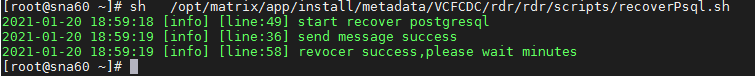
[root@node1 ~]# sh /opt/matrix/app/install/metadata/VCFCDC/rdr/rdr/scripts/recoverPsql.sh
2. If the execution result is as shown in Figure 4, the restoration succeeded. Wait a few minutes, and log in to the primary site to identify whether the data sync state of the component is Synced.
Figure 7 Database successfully restored
3. If the problem persists, contact H3C Support.
