- Released At: 17-07-2023
- Page Views:
- Downloads:
- Table of Contents
- Related Documents
-
H3C PSR560-56D Power Module
User Manual-6PW101
BOM:3101A0LU
Power module overview
PSR560-56D is a DC-input and DC-output power module. It provides a maximum output of 560 W and provides the following features:
Table 1 Features
|
Feature |
Description |
|
Protection |
Protection against overcurrent input, undervoltage input, overvoltage output, output current limiting, output short circuit, and overtemperature. |
|
Redundancy |
When you install two power modules on a device, the two power modules support 1+1 redundancy and load sharing. |
|
Hot swapping |
You can install or remove a power module when the switch is operating. |
Technical specifications
Table 2 Technical specifications
|
Item |
Specifications |
|
Rated input voltage |
–48 VDC to –60 VDC |
|
Maximum input voltage |
–36 VDC to –72 VDC |
|
Maximum input current |
20 A |
|
Output voltage |
56 V |
|
Output current |
10 A |
|
Maximum output power |
560 W |
|
Dimensions (H × W × D) |
40.1 × 82.6 × 259.5 mm (1.58 × 3.25 × 10.22 in) |
|
Operating temperature |
–10°C to +55°C (14°F to 131°F) |
|
Relative humidity |
5% to 95%, noncondensing |
Appearance
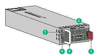
Figure 1 Appearance
|
(1) Input status LED (IN OK) |
(2) DC-input power receptacle |
|
(3) Latch |
(4) Handle |
|
(5) Output status LED (OUT OK) |
|
LEDs
The power module has two status LEDs on its front panel.
Table 3 LED description
|
LED |
Status |
Description |
|
Input status LED (IN OK) |
Steady green |
The power input is normal. |
|
Off |
No power input or the power input is abnormal. |
|
|
Output status LED (OUT OK) |
Steady green |
The power output is normal. |
|
Steady red |
The power output is abnormal. |
|
|
Off |
No power output. |
Installing and removing the power module
Safety precautions
To avoid possible bodily injury and power module and device damage, follow these safety precautions:
· When you install and remove the power module, always wear an ESD wrist strap and make sure it makes good skin contact and is reliably grounded.
· Before you install the power module, make sure the voltage of the power source is as required by the power module, and the output voltage of the power module is as required by the device.
· Do not touch any cables or terminals of the power module.
· Do not place the power module in a wet area, and prevent liquid from flowing into the power module.
· To avoid power module damage, do not open the power module. When the internal circuits or components of the power module fail, contact H3C Support.
Tools
Prepare an ESD wrist strap and a flat-blade screwdriver yourself.
Installing and removing the power module
Make sure the power module model is compatible with the device. For more information about hardware compatibility, see the installation guide for the device.
Installing the power module
To avoid bodily injury or device damage, follow the procedure in Figure 2 to install the power module.
Figure 2 Installation procedure
![]()
To install the power module:
1. Wear an ESD wrist strap and make sure the strap makes good skin contact and is reliably grounded.
2. Unpack the power module and verify that the power module model is as required.
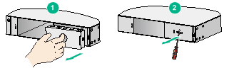
3. Remove the filler panel as shown in Figure 3, if any, from the target power module slot.
? Put your finger into the hole in the filler panel and pull the filler panel out along the guide rails.
? Insert a flat-blade screwdriver through the handle on the filler panel and pull the filler panel out along the guide rails.
Figure 3 Removing a filler panel
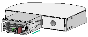
4. Insert the power module into the slot, as shown in Figure 4:
a. Correctly orient the power module with the characters upward.
b. Holding the power module handle with one hand and supporting the power module bottom with the other, slide the power module along the guide rails into the slot. When the power module is completely inserted into the slot, you can hear that the latch of the power module clicks into the slot.
If the power module is not aligned with the slot, pull out the power module, adjust its direction, and insert it again.
Figure 4 Installing the power module
|
|
IMPORTANT: Keep the filler panel and the packaging box and packaging bag of the power module for future use. |
Connecting the DC power cord
|
|
WARNING! · Make sure the power cord has a separate circuit breaker. · Turn off the circuit breaker before connecting the power cord. |
|
|
IMPORTANT: Use the DC power cord provided with the power module. |
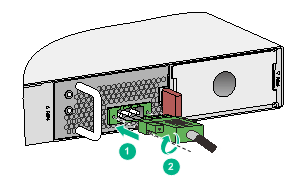
1. As shown in Figure 5, plug the female connector end of the DC power cord into the DC-input receptacle on the power module.
2. Use a flat-blade screwdriver to fasten the screws on the female connector to secure the power cord to the receptacle.
3. Connect the other end of the DC power cord to the DC power source, and turn on the circuit breaker.
4. Examine the IN OK LED on the power module. If the LED is steady green, the power cord is connected correctly. If the LED is off, examine the installation, troubleshoot the problems, and try again until the LED is steady green.
Figure 5 Connecting the DC power cord
Removing the power module
To avoid bodily injury or device damage, follow the procedure in Figure 6 to remove the power module.
![]()
To remove the power module:
1. Turn off the circuit breaker at the power input end.
2. Wear an ESD wrist strap and make sure the strap makes good skin contact and is reliably grounded.
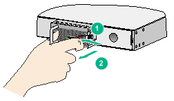
4. As shown in Figure 7, press the latch towards the handle, and pull the power module part way out of the slot along the guide rails.
5. Holding the power module handle with one hand and supporting the power module bottom with the other, pull the power module slowly out of the slot along the guide rails.
6. Put the removed power module on an antistatic mat or into its package.
7. If you are not to insert a power module into the empty slot, insert the filler panel into the slot to prevent dust from entering the chassis.
Figure 7 Removing the power module
Copyright © 2016-2017 New H3C Technologies Co., Ltd.
