| Title | Size | Downloads |
|---|---|---|
| DDC Cloud Cluster Technology White Paper-6W100-book.pdf | 5.39 MB |
- Table of Contents
- Related Documents
-
| Title | Size | Download |
|---|---|---|
| book | 5.39 MB |
DDC Cloud Cluster Technology White Paper
Copyright © 2025 New H3C Technologies Co., Ltd. All rights reserved.
No part of this manual may be reproduced or transmitted in any form or by any means without prior written consent of New H3C Technologies Co., Ltd.
Except for the trademarks of New H3C Technologies Co., Ltd., any trademarks that may be mentioned in this document are the property of their respective owners.
This document provides generic technical information, some of which might not be applicable to your products.
Contents
Weaknesses of traditional switches
Physical architecture of DDC cloud cluster
Overview of physical devices in DDC cloud cluster
Control plane topology of DDC cloud cluster
Data plane topology of DDC cloud cluster
Application scenarios of DDC cloud cluster
Highlights of DDC cloud cluster
Virtualization mechanism in the control plane of DDC cloud cluster
Dual-cluster virtualization architecture
Operating mechanism of physical cluster
Setup of the management network
Splitting of the physical cluster
Operating mechanism of container cluster
Set up of the container cluster (master election)
Split of the container cluster
Operating mechanism and advantages of DDC cloud cluster data plane
Generation and synchronization of forwarding entries
Unified cloud cluster configuration management
Applications of DDC cloud clusters in high performance computing
DDC cloud cluster overview
Background
With the rapid development of big data, cloud computing, and artificial intelligence (AI) technologies, data centers need to accommodate traffic surge, which put immense pressure on their core switches.
Weaknesses of traditional switches
Traditionally, modular switches act as core switches in data centers. Each modular switch is an enclosed, centralized, and large chassis. All switch components, such as routing engines, switching modules, and interface cards are housed within a large-size chassis. Although this design allows centralized management, it is weak in scalability, flexibility, and cost-effectiveness. As switching chips advance and switching capacity increases (from 100 G to 400 G), traditional modular switches have a significant increase in power consumption. For example, a 16-slot modular switch with all 400-G ports requires a power supply of up to 40000 to 50000 watts. This requirement makes upgrading devices in old data centers a significant challenge, especially when the power supply cannot meet this requirement.
DDC technology
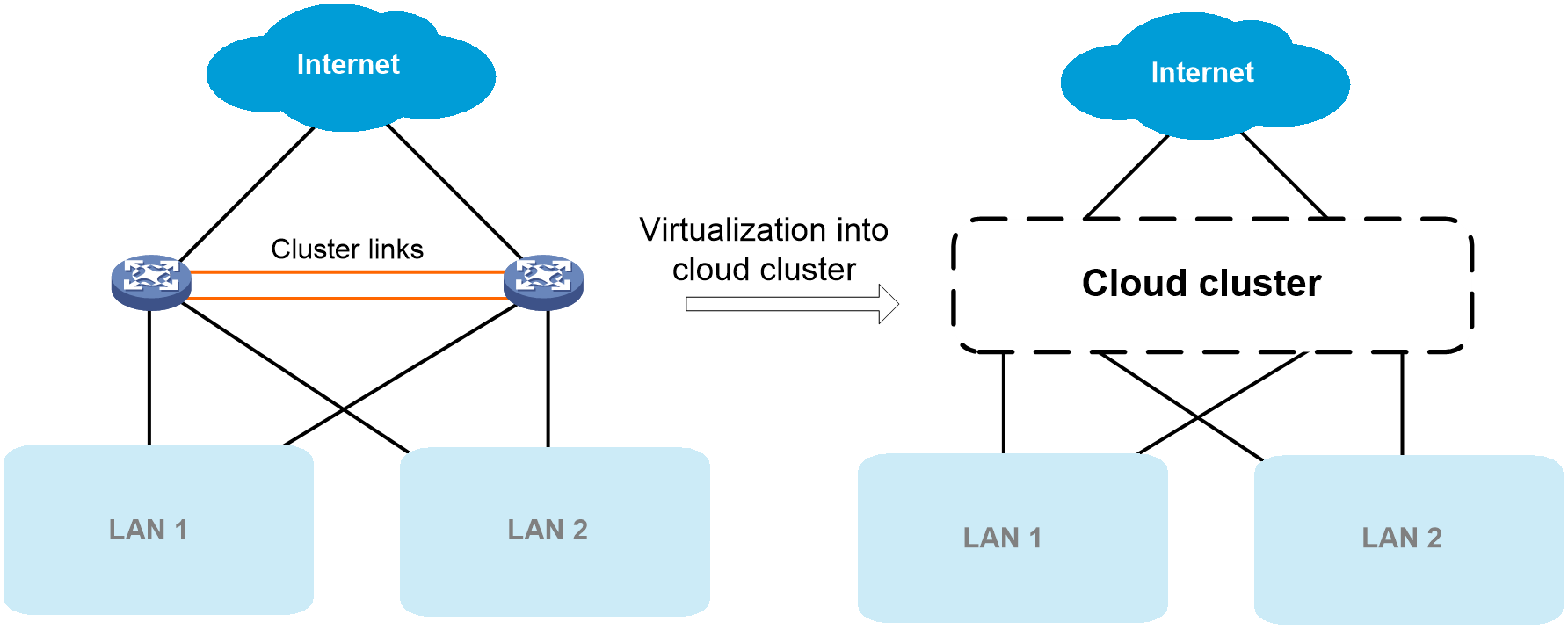
Distributed Disaggregated Chassis (DDC) is a network architecture that breaks down traditional switches (modular chassis switches) into smaller components. These components are connected through high-speed networks and allow flexible switch assembly. In the DDC architecture, network components, such as routing, switching, and the control plane, are physically separated and distributed across different hardware devices. These devices can be independently expanded to provide higher flexibility, scalability, and cost efficiency. Additionally, they can be dispersed across multiple cabinets, which allows better cooling management and power consumption control, and facilitates device upgrade and space expansion.
Cloud cluster technology
Cloud cluster is a software virtualization technology independently developed by H3C. Based on the containerized architecture of Comware 9, this technology decouples applications from physical devices as much as possible. A cloud cluster is divided into the following layers:
· Physical cluster: The core idea of a physical cluster is to connect multiple physical devices and virtualize them into a single device after necessary configuration. Using this virtualization technology can integrate hardware resources from multiple devices. On one hand, it enables unified management and allocation of hardware resources from multiple devices, increasing resource utilization and reducing management complexity. On the other hand, it also achieves hardware-level backup, which enhances the reliability of the entire system.
· Container cluster: The core idea of a container cluster is to logically connect containers running on physical devices and virtualize those containers into a single system after necessary configuration. Using this virtualization technology can integrate software processing capabilities from multiple containers. It enables collaborative operation, unified management, and uninterrupted maintenance of multiple containers.
DDC cloud cluster
DDC cloud cluster is an application of the H3C cloud cluster technology in DDC networks.
· In terms of physical form, each DDC cloud cluster is deployed in DDC distributed architecture where the following roles are involved:
¡ Network cloud controller (NCC): DDC controller.
¡ Network cloud processor (NCP): DDC service module.
¡ Network cloud fabric (NCF): DDC switching fabric module.
NCCs, NCPs, and NCFs are all independent physical devices.
· At the management layer, centralized management is implemented through device virtualization. The cloud cluster technology virtualizes physical devices in the DDC architecture into a centralized modular mega-switch. The switch uses NCCs as MPUs, NCPs as service modules, and NCFs as switching fabric modules.
Physical architecture of DDC cloud cluster
Overview of physical devices in DDC cloud cluster
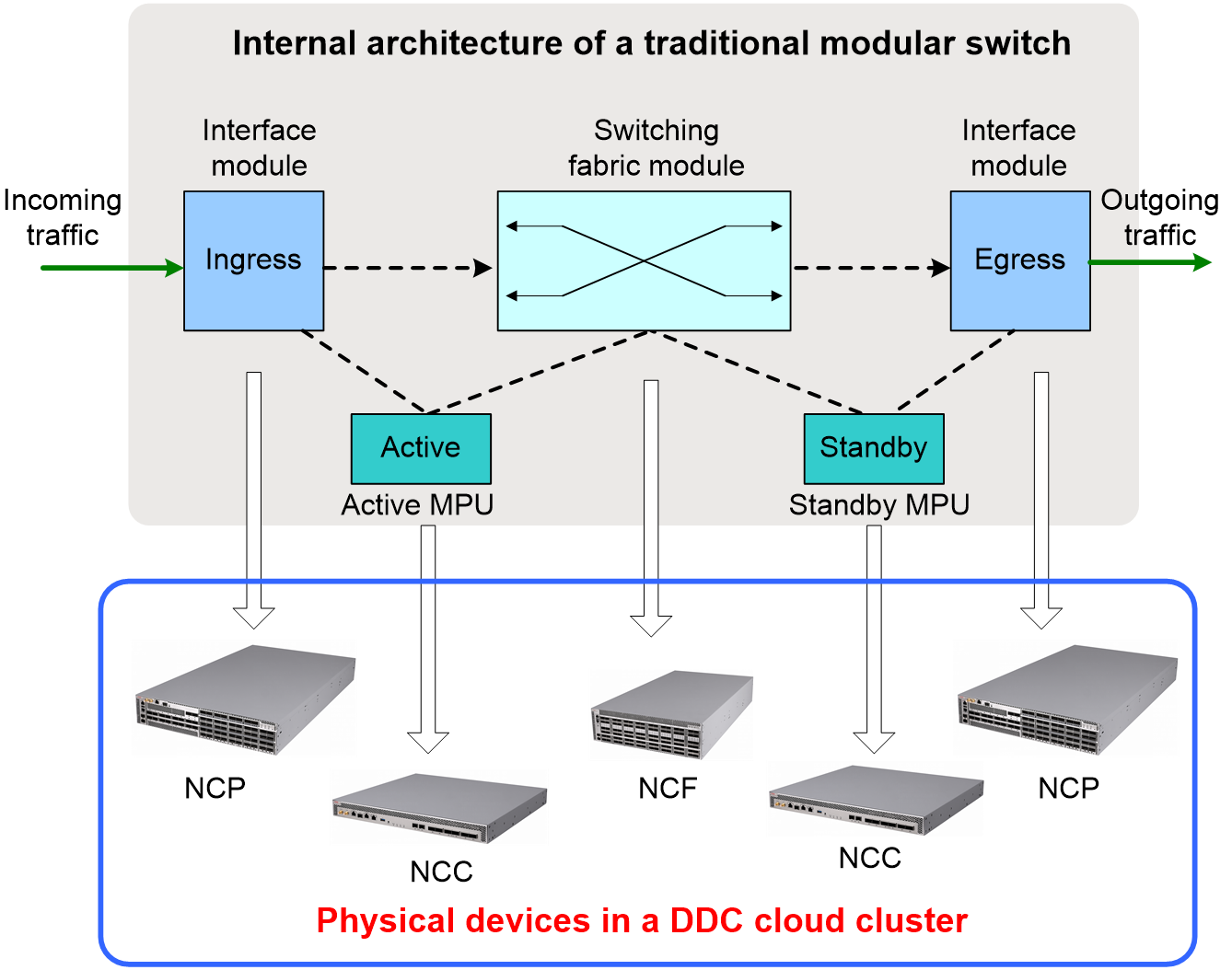
As shown in Figure 2, the H3C DDC solution decouples a traditional modular switch into three types of physical devices, including NCC, NCP, and NCF.
Figure 2 Physical architecture of a DDC cloud cluster
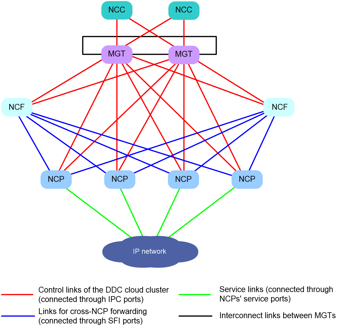
NCCs, NCPs, and NCFs use Inter-Process Communication (IPC) interface to transmit control packets. NCPs and NCFs use SerDes Framer Interface (SFI) interfaces to transmit data packets. Table 1 shows the port matrix for the S12500AI switch series.
Table 1 Port matrix for the S12500AI switch series
|
Product series |
Chassis type |
Product model |
Available interfaces |
|
H3C S12500AI switch series |
NCC |
S12500AI-6C-NCCA |
· 2 x SFP28 IPC interfaces · 6 x QSFP28 IPC interfaces |
|
NCF |
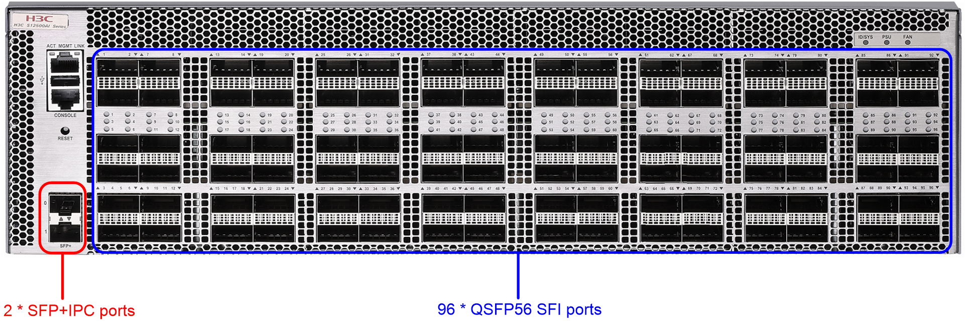
S12500AI-96B-NCFK |
· 2 x SFP+IPC interfaces · 96 x QSFP56 SFI interfaces |
|
|
NCP |
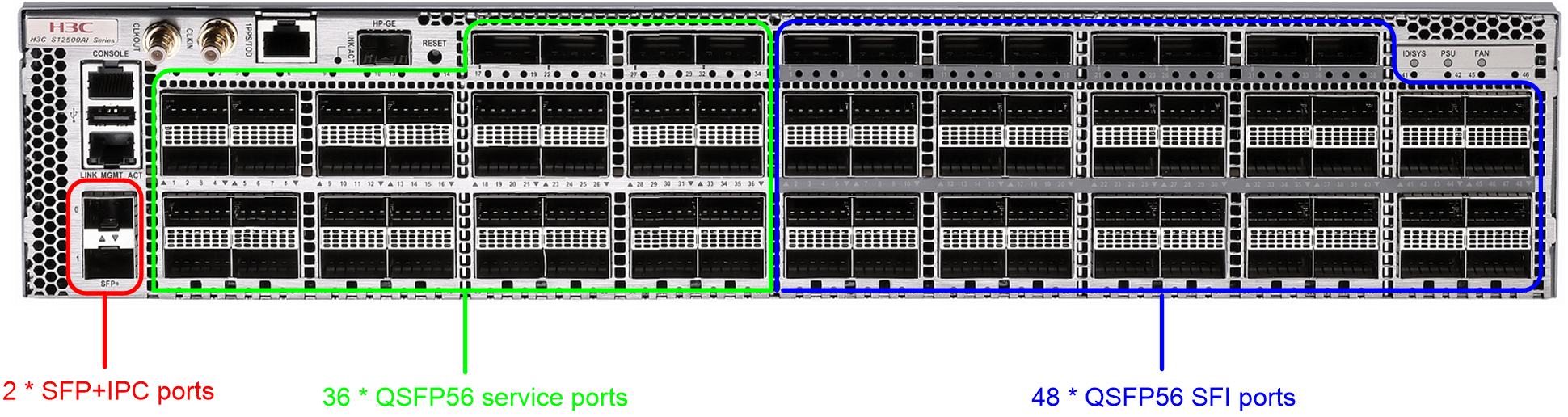
S12500AI-36B48B-NCPK |
· 2 x SFP+IPC interfaces · 48 x QSFP56 SFI interfaces · 36 x QSFP56 service interfaces |
|
|
S12500AI-18D48B-NCPK |
· 2 x SFP+IPC interfaces · 48 x QSFP56 SFI interfaces · 18 x QSFP-DD service interfaces |
|
|
NOTE: As a best practice to enhance network reliability, make sure the DDC cloud cluster contains a minimum of two physical devices for each DDC role (including NCC, NCP, and NCF). |
Network cloud controller
NCC functions similarly as the MPU of an S12500R switch. It provides centralized management of NCPs and NCFs, deploys configurations, collects log information, processes protocol packets, and generates data entries for the control plane and data plane.
Typically, a minimum of two NCCs are deployed in a DDC cloud cluster.
· One NCC acts as the active MPU.
· The other NCC acts as the standby NCC. It seamlessly takes over the services running on the active NCC only if the active NCC fails.
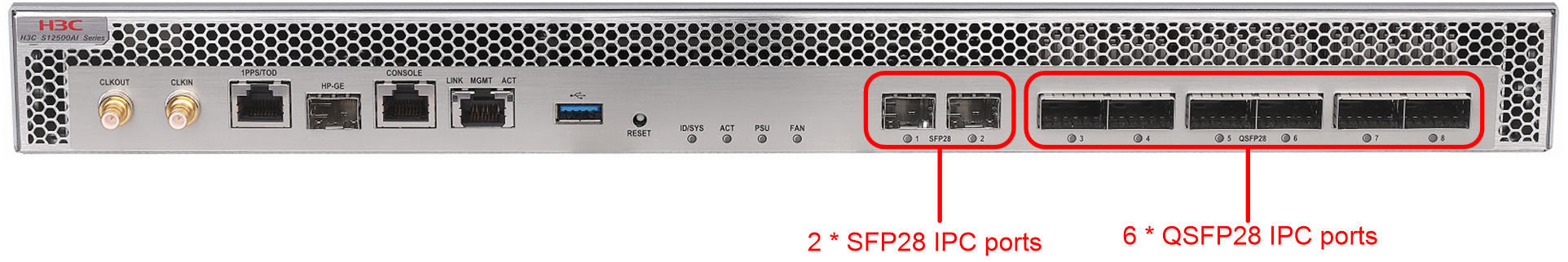
In the vSwitch virtualized from a DDC cloud cluster, the NCCs function as MPUs. The slot number range for NCCs is 1 to 8, and you can specify the slot number of each NCC as needed.
Figure 3 S12500AI-6C-NCCA front panel
Network cloud processor
NCP functions similarly as the service module of an S12500R switch, which is responsible for packet forwarding. The service ports of a NCP are connected to service networks, allowing the DDC cloud cluster to communicate with external networks.
In the vSwitch virtualized from a DDC cloud cluster, the NCPs function as service modules. The slot number range for NCPs is 11 to 106, and you can specify the slot number of each NCP as needed.
Figure 4 S12500AI-18D48B-NCPK front panel
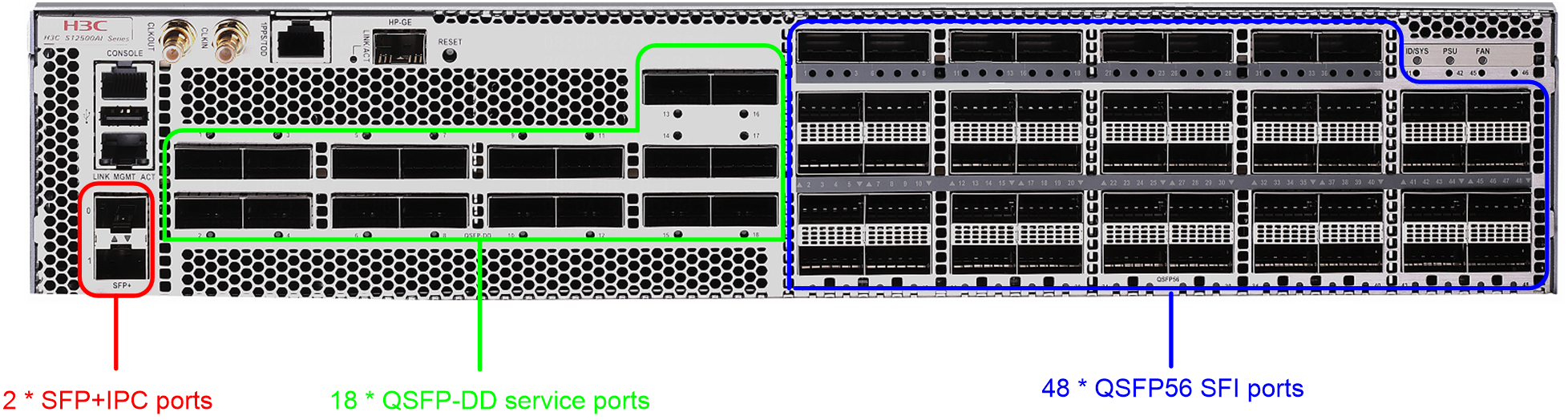
Figure 5 S12500AI-36B48B-NCPK front panel
Network cloud fabric
NCF functions similarly as the switching fabric module of an S12500R switch. If the input and output interfaces of a packet are located on different NCPs, the related NCF forwards that packet to the egress NCP.
In the vSwitch virtualized from a DDC cloud cluster, the NCFs function as switching fabric modules. The slot number range for NCFs is 140 to 187, and you can specify the slot number of each NCF as needed.
Figure 6 S12500AI-96B-NCFK front panel
Management switch
A management switch (MGT) is an IPv6-capable Layer 3 switch that establishes a physical management network with the DDC cloud cluster. NCCs, NCPs, and NCFs all must be connected to the management switch.
The following table provides a list of recommended management switches:
Table 2 Recommended management switch models for DDC cloud cluster setup
|
Device model |
Ports |
Recommended versions |
|
S6850-56HF (Product code: LS-6850-56HF-H1) |
48*10/25G + 8*40/100G |
Release 6710+HS11 |
|
S6850-56HF (Product code: LS-6850-56HF-H3) |
48*10/25G + 8*40/100G |
Release 6710P03 |
|
S6825-54HF |
48*10/25G + 6*40/100G |
Release 6710+HS11 |
|
S6890-54HF |
48*10G + 6*100G |
Release 2719P01 |
|
S12500R-48Y8C |
48*25G + 8*100G |
Release 5212P01 |
Control plane topology of DDC cloud cluster
When you use IPC interfaces to set up the control plane of a DDC cloud cluster, follow these restrictions and guidelines:
· As a best practice to enhance the reliability of the control plane, use a minimum of two management switches to set up the control plane.
· To enhance the reliability of the management network, make sure the management switches form a ring topology with their Layer 3 interfaces.
· Each NCC has multiple IPC interfaces. When you connect an NCC to different management switches, make sure the connected NCC IPC interfaces are at the same speed.
· Each NCP or NCF has two IPC interfaces, which must be connected to management switches. As a best practice to enhance link reliability, connect the two interfaces to different management switches.
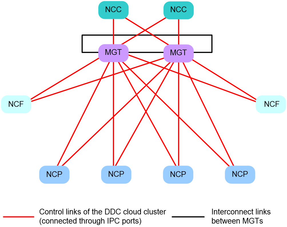
As shown in Figure 7, NCPs and NCFs each are connected to different management switches. As a best practice, connect each NCC to different management switches. The management switches form a ring network and forward control-plane packets (such as management packets and protocol packets) within the DDC cloud cluster.
Figure 7 Control plane topology of a DDC cloud cluster

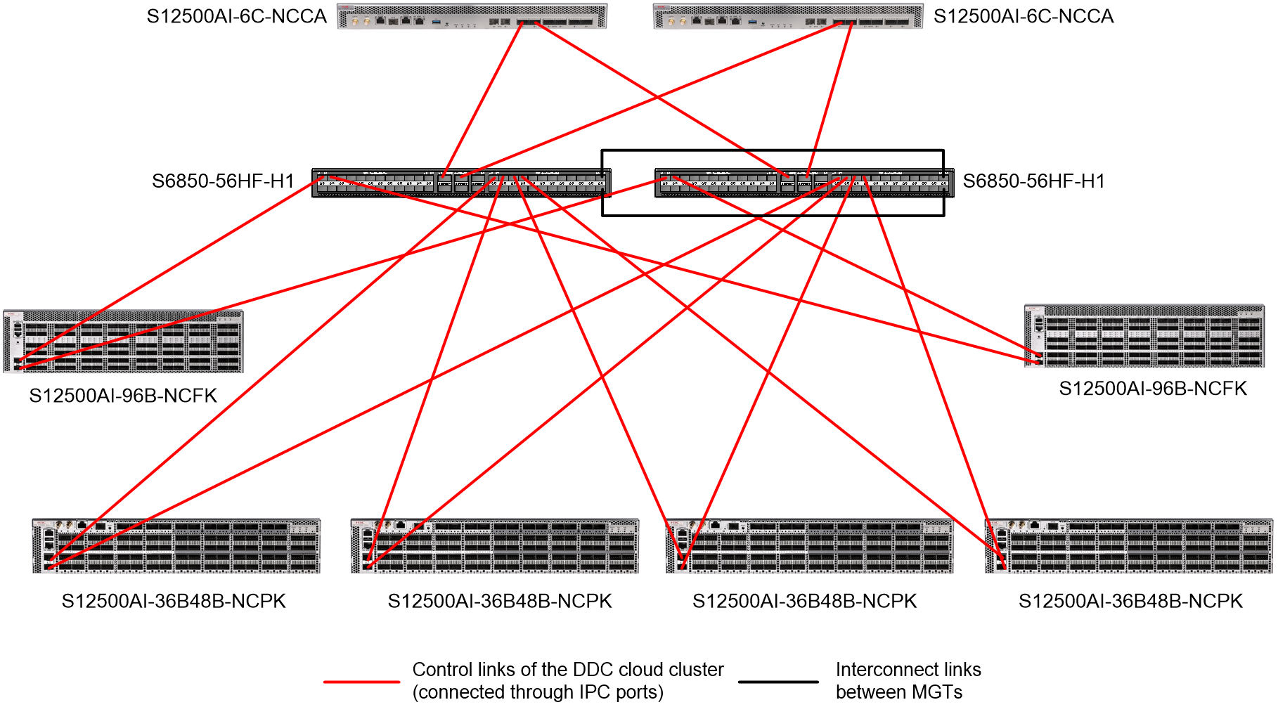
Figure 8 shows the connections among physical devices at the control plane. In this example, the device models of management switches and NCPs are S6850-56HF-H1 and S12500AI-36B48B-NCPK, respectively.
Figure 8 Physical device connections at the control plane of a DDC cloud cluster
Data plane topology of DDC cloud cluster
When you set up the data plane of a DDC cloud cluster, follow these restrictions and guidelines:
· The number of NCPs and NCFs depends on the network size. As a best practice, make sure the ratio of NCPs and NCFs is 2:1.
· NCPs and NCFs should form a full mesh topology with their SFI interfaces.
Table 3 shows the pluggable transceiver modules supported by SFI interfaces.
Table 3 Pluggable transceiver modules supported by SFI interfaces
|
BOM |
Description |
|
0231AJHS |
200G QSFP56 Multimode Optical Transceiver Module (850nm,100m,OM4,70m OM3,SR4,MPO12/UPC) |
|
0231AJHU |
200G QSFP56 Optical Transceiver Module (1300nm,2km,FR4,SMF/LC) |
|
0231AL4N |
QSFP56-200G-D-AOC-5M (Hisense) |
Figure 9 shows the typical data plane topology of a DDC cloud cluster.
Figure 9 Data plane topology of a DDC cloud cluster
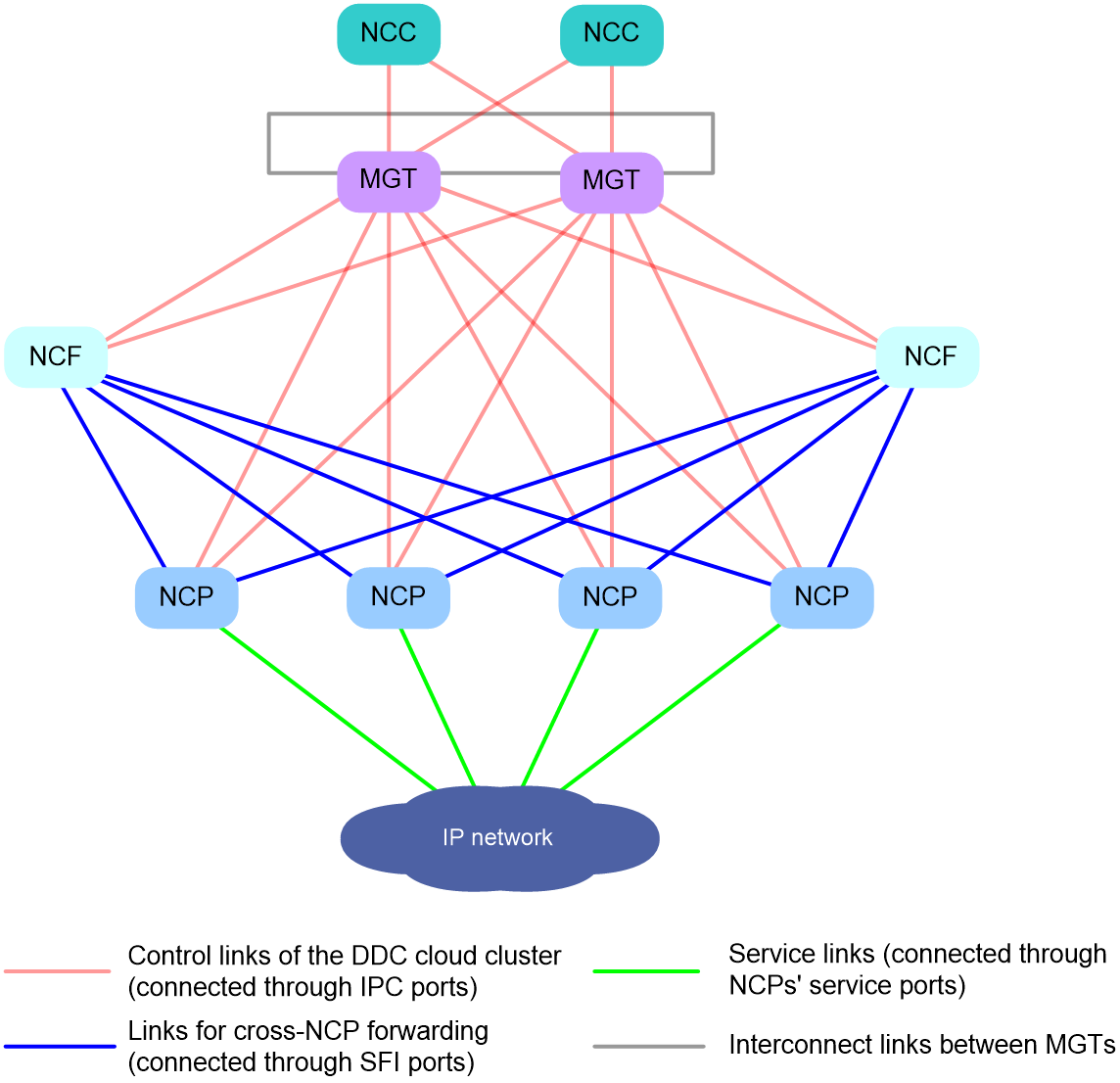
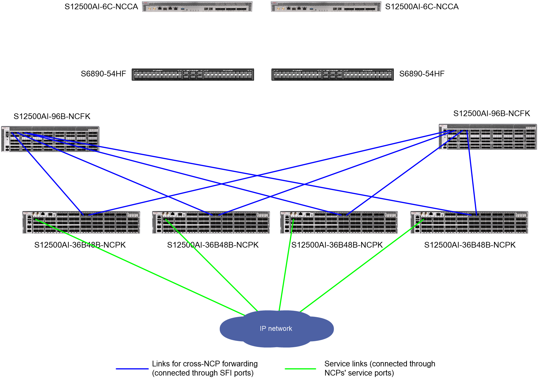
Figure 10 shows the connections among physical devices at the data plane. In this example, the device model of NCPs is S12500AI-36B48B-NCPK.
Figure 10 Physical device connections at the data plane of a DDC cloud cluster
Application scenarios of DDC cloud cluster
The DDC cloud cluster technology is suitable for building modernized, scalable, and flexible data center networks, especially in scenarios such as cloud computing, big data, and distributed storage.
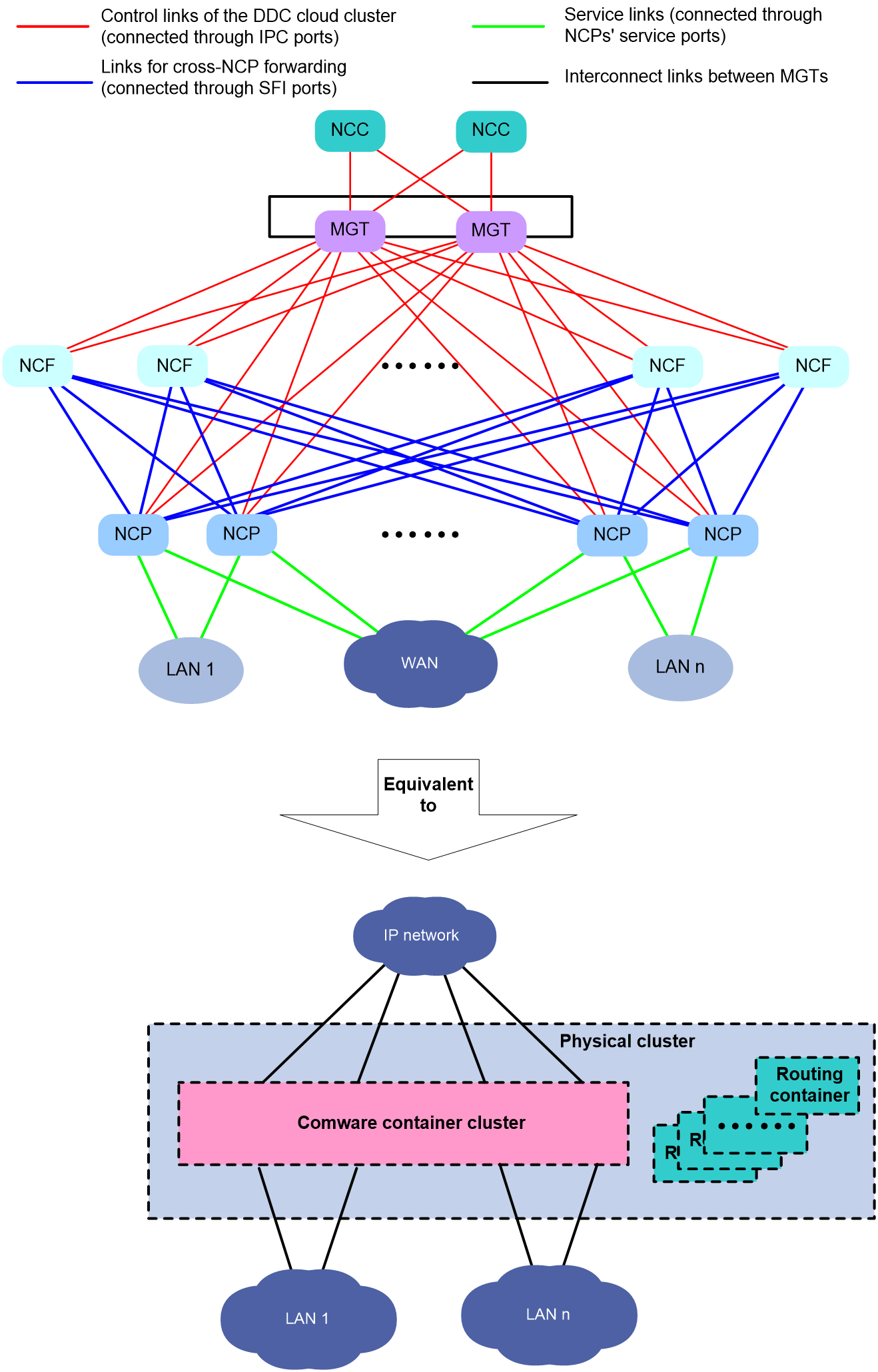
As shown in Figure 11, the DDC cloud cluster includes two NCCs and multiple NCFs and NCPs. The NCCs, NCFs, and NCPs are all connected to the management switches. The DDC cloud cluster technology virtualizes those devices into different modules of a single device. For upstream and downstream devices, the entire DDC cloud cluster appears to be one network device (corresponding to the container cluster in Figure 11) that is similar to a modular superswitch. This virtual network device owns and manages all resources from the related physical devices.
Figure 11 DDC cloud cluster network
Highlights of DDC cloud cluster
The DDC cloud cluster technology provides the following benefits:
· Superior scalability
The DDC architecture allows on-demand network expansion. You can add more units as needed to increase network capacity, ports, and bandwidth. This enhances the service, computing, storage, and processing capabilities of the system without the need to replace the entire switch.
· Enhanced reliability
The DDC cloud cluster supports device-level, protocol-level, and link-level backups to enhance device reliability and ensure nonstop device operation.
· Ultraspeed traffic forwarding
The DDC cloud cluster uses advanced hardware technologies for traffic forwarding, such as Virtual Output Queuing (VOQ) and CELL switching. The VOQ technology prevents packet loss during packet forwarding within the cloud cluster. The CELL forwarding technology ensures better load sharing within the cloud cluster, and increases the utilization and throughput of links between NCPs and NCFs. The two technologies works together to ensure low forwarding delay and packet loss, which meets the transport network requirements of High Performance Computing (HPC) services.
· Easy operations and maintenance
The entire cloud cluster is virtualized into a single network node, which simplifies configurations of the network topology and the upstream and downstream devices.
Member devices in the cloud cluster support configuration synchronization, which also simplifies device configurations.
DDC is highly modularized, so you can scale up or down NCCs, NCPs, and NCFs as needed, and upgrade or maintain each of them separately. Additionally, with the DDC architecture, you can perform fine network resource management based on the traffic forwarding method and service demands, improving the resource efficiency.
· Flexible deployment
The cloud cluster is divided into two layers, including physical cluster and container cluster. The underlying devices are decoupled from services, which increases the flexibility of the cloud cluster and allows fast cloud deployment at enterprises.
· Green and environmental protection
The DDC architecture improves energy efficiency, because it reduces power consumption and cooling requirements by providing support for precise capacity planning and dynamic power management.
Virtualization mechanism in the control plane of DDC cloud cluster
Dual-cluster virtualization architecture
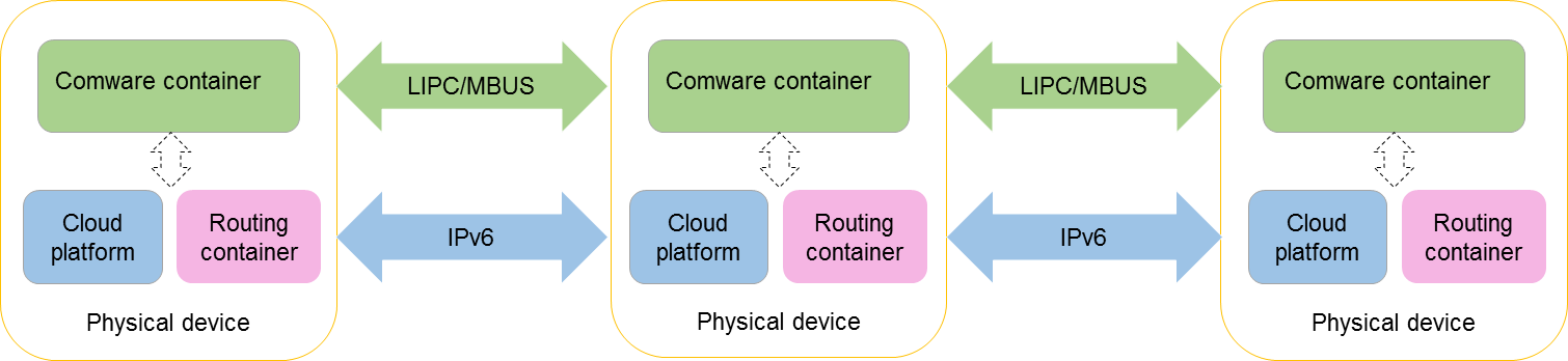
Based on the containerized architecture of Comware 9, the DDC cloud cluster technology achieves virtualization at both the service and physical device levels. The startup software packages for NCCs, NCPs, and NCFs contain cloud platform software modules, routing container images, and Comware container images.
The cloud platform software modules, routing containers, and Comware containers work together to achieve dual-layer virtualization in the cloud cluster.
· Cloud platform software modules run on different physical devices and communicate through Layer 3 channels, virtualizing multiple physical devices into one physical cluster. This cluster provides management services for upper-level services, such as deploying containers, providing unified resource management and fault monitoring for containers, and discovering and managing container topologies.
· Containers also run on physical devices to provide services.
The following containers run in the DDC cloud cluster:
¡ Routing container: NCCs, NCPs, and NCFs each run a routing container. The container contains IPC interfaces (interface type: EthIPCChannel) to achieve device interconnects at the control plane.
¡ Comware container: Known as the base container, a container that runs the Comware system to provide basic communication functions for devices, such as routing and switching. In the current software version, only Comware containers can be virtualized into a container cluster. Comware containers communicate through Leopard Inter-process Communication (LIPC) and Management Bus (MBUS) channels to form a single container cluster.
Figure 12 Software architecture of a DDC cloud cluster
As shown in Figure 13, the physical devices in a cloud cluster are virtualized into a physical cluster and a container cluster.
Figure 13 Logical architecture of a cloud cluster
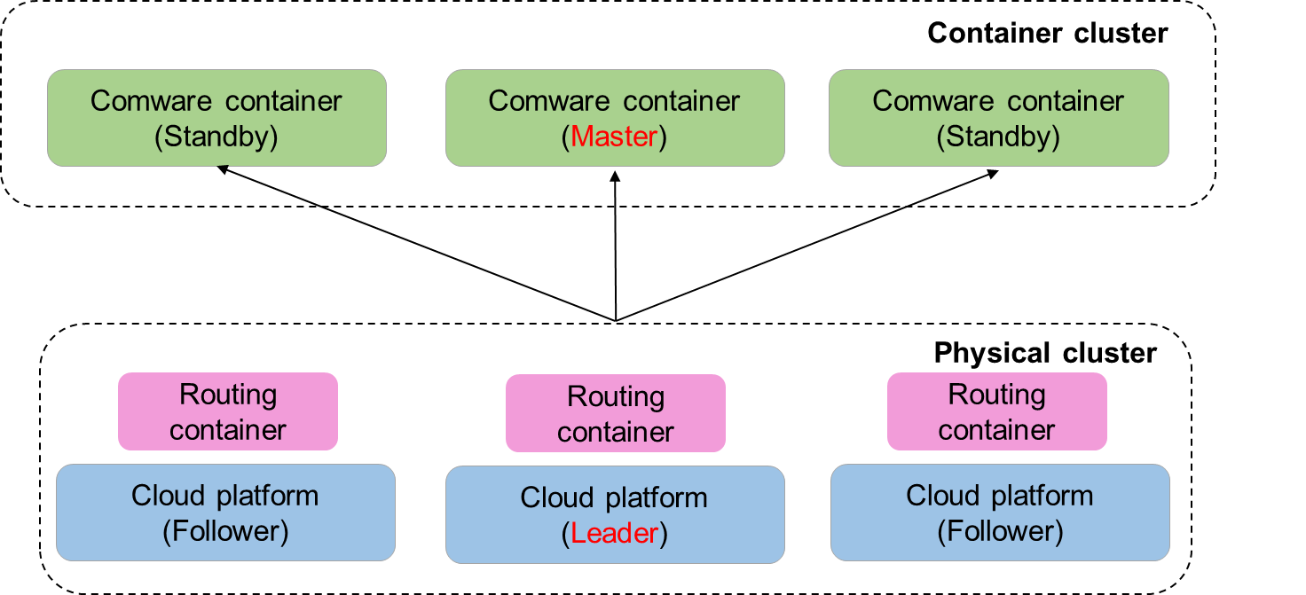
Operating mechanism of physical cluster
Basic concepts
Member device roles
Every device in the physical cluster is called a member device. Member devices are divided into two roles based on their functions:
· Manager: Responsible for cloud platform HA, cluster setup, and cluster member management. It provides the following functions:
¡ Manages the physical cluster, including cluster setup, cluster maintenance, member management, and cluster topology generation and update.
¡ Manages the container cluster, intelligently deploys Comware containers based on the distribution of hardware resources in the physical cluster, and elects the primary and subordinate containers of the container cluster.
Managers are further divided into leader and followers depending on their responsibilities.
¡ Leader: Primary manager, responsible for managing and controlling the entire cloud cluster, acting as the control center.
¡ Follower: Backup manager. A follower manager also handles services and forwards packets. When the leader fails, the system automatically elects a new leader from the followers.
¡ In the DDC cloud cluster, all NCCs act as managers. They perform a leader election to determine the leader. Only one of them can be elected as the leader, and the remaining NCCs are followers.
· Worker: Responsible for local node management. It reports node resources to the leader, and deploys containers as instructed by the scheduling messages received from the leader.
When devices are configured as workers, the devices automatically run the worker component to provide the relevant functions.
In the DDC cloud cluster, all NCCs, NCPs, and NCFs are workers.
Member ID
In a DDC cloud cluster, a physical device is uniquely identified by a member ID. Member IDs are used during the setup and maintenance of both physical and container clusters.
In a cloud cluster, only one device can use the default member ID, and the other devices can join the cluster only after you modify their member IDs. When you modify member IDs, make sure they are unique within the cloud cluster.
· During the setup of a physical cluster, if two devices have the same member ID, the device that registers later cannot join the physical cluster.
· During the operation of a physical cluster, if a new device tries to join but its member ID conflicts with an existing member's ID, the device cannot join the physical cluster.
The default member ID is 1 for NCCs. You can change the member ID of an NCC by using the cloud-cluster member member-id renumber new-member-id command. The member IDs of NCPs and NCFs depend on the specified member ID mapping file.
Member ID mapping file
The member ID mapping file is used for SlotID assignment to NCPs and NCFs, so they can automatically form a cloud cluster.
The mapping file is a .csv file that contains three columns: serial number, MAC address, and SlotID. These columns record the mappings between physical devices and SlotIDs. Both the serial number and the MAC address can uniquely identify a physical device. When you configure a member ID mapping for a device in the mapping file, specify that device by either its serial number or its MAC address.
The content of the member ID mapping file is as follows:
Serial Number,MAC Address,Slot number
210231AE3BH20BXXXXXX1,00e0-fc00-0001,10
210231AE3BH20BXXXXXX2,00e0-fc00-0002,11
The file is stored on the storage media of NCCs and the NCPs hosting failover containers. When an NCP or NCF registers with the NCC, the NCC searches the member ID mapping file for a matching SlotID based on the NCP’s or NCF's serial number and MAC address. The NCC then assigns the found SlotID to the NCP or NCF. On receipt of the SlotID, the NCP or NCF generates a MemberID whose value equals that of the received SlotID.
For more information about failover containers, see “DDC cloud cluster HA.”
Setup of the management network
When an NCC, NCP, or NCF starts, it runs a routing container that contains IPC interfaces (interface type: EthIPCChannel). To set up the management network of a DDC cloud cluster, connect the IPC interfaces of each member device to the management switches. Each device uses IPv6 and link local address for communication, uses IS-IS for unicast route control, and uses PIM for IPv6 multicast route control. The multicast address is FF1E::1.
Additionally, you must create a Loopback interface on each management switch. The IPv6 address of that interface is in a format of 2017:61E:81E:0:XXXX:XXFF:FEXX:XXXX, where Xs are variables that can be replaced with hexadecimal numbers as needed.
Setup of the physical cluster
Setting up the physical cluster involves the following steps:
1. Discovery of routing nodes: Each NCC, NCP, and NCF runs a routing container. Those containers all use IS-IS to enable node discovery and communication within the cluster, and to generate a routing table for the management network.
2. Discovery of physical nodes: Nodes in the cluster exchange information by unicasting messages to each other through IS-IS. The exchanged information includes domain ID, member ID, member role (manager or worker), and member identity (leader or follower), enabling the members to identify and connect to each other.
3. Leader election: In a DDC cloud cluster, only NCCs can manage the physical cluster. When multiple NCCs exist in the DDC cloud cluster, the NCC with the smallest member ID is selected as the leader.
By default, the member ID of each NCC is 1. After you select one NCC as the leader, you must log in to the other NCCs separately, and then change their member IDs by using the cloud-cluster member renumber command.
4. Node adding and resource allocation: After an NCC is elected as the leader, it unicasts device information to other nodes (including NCCs, NCPs, and NCFs).
¡ After receiving messages from the leader, NCPs and NCFs request member IDs from the leader. The leader then assigns member IDs from the member ID mapping file to NCPs and NCFs. On receipt of the assigned member Ids, the NCPs and NCFs register with the leader to join the cloud cluster.
¡ After receiving messages from the leader, the other NCCs register with the leader to join the cloud cluster.
Splitting of the physical cluster
After the leader NCC is disconnected from a follower NCC, the follower NCC marks the leader NCC down, and then forms a new physical cluster with its downstream NCFs and NCPs. Consequently, the original physical cluster is split into two physical clusters. The new physical clusters each perform leader election based on the rule of smallest member ID to select their own leader NCCs.
Merge of physical clusters
After the link fault between two physical clusters is removed, the two clusters automatically merge into one physical cluster. During the merge, a leader election is triggered and only one leader is retained. Leader in the winning physical cluster becomes the leader of the entire physical cluster, and leader in the losing cluster joins the physical cluster as a follower.
The two physical clusters perform a leader election under the following rules:
1. The physical cluster with more NCPs wins.
2. The physical cluster with a smaller leader member ID wins.
|
|
NOTE: Typically, the merge of physical clusters also involves a container cluster merge. During the merge, physical devices do not restart. The container cluster associated with the losing physical cluster automatically restarts and joins the container cluster associated with the winning physical cluster. |
Operating mechanism of container cluster
Basic concepts
Member container roles
Each container in a container cluster is called a member container. Member containers are divided into the following roles according to their functions:
· Master container: Responsible for managing and controlling the entire container cluster.
· Standby container: Acts as a backup container for the master container. A standby container also handles services and forwards packets. When the master fails, the system automatically elects a new master from the standby containers.
· IO container: Acts as a service module in the DDC cloud cluster, providing packet forwarding services.
When the physical cluster runs correctly, the master and standby roles are determined by the leader of the physical cluster. When the physical cluster fails, both the master and standby containers are selected through election.
Only one master container exists in a container cluster, and all the other member containers are standby containers.
Container ID
In a container cluster, each container is uniquely identified by its container ID. Member containers run on physical devices, and their container IDs are assigned by the leader of the physical cluster.
In a DDC cloud cluster, a physical device is uniquely identified by its member ID. You can use the member ID of a physical device as the container ID to uniquely identify the container running on that device.
In a cloud cluster, only one device can use the default member ID, and the other devices can join the cluster only after you modify their member IDs. When you modify member IDs, make sure they are unique within the cloud cluster.
· During the setup of a physical cluster, if two devices have the same member ID, the device that registers later cannot join the physical cluster.
· During the operation of a physical cluster, if a new device tries to join but its member ID conflicts with an existing member's ID, the device cannot join the physical cluster.
Container cluster domain
Container cluster domain is a logical concept, and one container cluster corresponds to one container cluster domain.
To accommodate various network applications, multiple container clusters can be deployed in a network, and the container clusters are distinguished by domain IDs.
Set up of the container cluster (master election)
Each NCC functions as an MPU of modular switch S12500R, providing centralized management of NCPs and NCFs. Therefore, the leader NCC of the physical cluster selects the Comware container running on an NCC as the master container. Comware containers running on the other NCCs are all standby containers. Comware containers running on either NCFs or NCPs are all IO containers.
During the master container election, the Comware container running on the leader NCC is selected as the master.
Split of the container cluster
The master container regularly sends heartbeat messages to standby containers, NCPs, and NCFs to retain their connections. If a standby container cannot receive a heartbeat message from the master before the timeout timer expires due to a link failure, it determines that the master is down. In this situation, a master election is automatically triggered among the standby containers. As a result, the DDC cloud cluster will have two masters. This symptom is called container cluster split.
· If NCPs and NCFs can receive heartbeat messages from the old master, they do not respond to the new master's heartbeat messages. Their Comware containers still run as IO containers under the management of the old master.
· If NCPs and NCFs cannot receive heartbeat messages from the old master before the timeout timer expires, they determine that the old master is down, and respond to the new master's heartbeat messages. Their Comware containers will then be managed by the new master.
Merge of container clusters
Operating mechanism
When the control links between two container clusters recover, the clusters automatically merge into one container cluster. During the merge, a master election is triggered. Only the winning container cluster keeps running. All members in the losing container cluster must restart to join the winning cluster.
The two container clusters perform a master election under the following rules:
1. The container cluster with more NCPs wins.
2. The container cluster with a non-failover master container wins.
3. The container cluster whose master container has a smaller member ID wins.
Technical highlights
The mechanisms of auto merge and master election ensures continuous cluster management and system stability. They not only optimize resource usage, but also reduce manual intervention, improving the efficiency and reliability of system recovery.
Operating mechanism and advantages of DDC cloud cluster data plane
Generation and synchronization of forwarding entries
Operating mechanism
The traditional Spine-Leaf DC network architecture adopts an old-fashioned distributed control plane though the use of controllers or unified operations scripts has simplified device configuration. In this network model, each device operates as an independent routing node that performs multiple routing operations, such as routing domain management and route information synchronization. This increases the complexity of route computation.
The DDC cloud cluster optimizes the traditional architecture by providing centralized control. In this model, NCPs do not run any routing protocols though they are connected to forwarding devices. Instead, the master container in the cloud cluster provides centralized management of routing protocols and forwarding paths. This design not only simplifies network configuration and reduces the risk of misconfiguration, but also improves the efficiency of route convergence and advertisement.
In a DDC cloud cluster, route entries are generated and synchronized as follows:
· If static routes are configured, the master container synchronizes static route entries with all NCCs, NCPs, and NCFs.
· If a dynamic routing protocol is deployed in the network, each NCP forwards received protocol messages to the master container for centralized processing. The master container then generates dynamic route entries and synchronizes them with all NCCs, NCPs, and NCFs.
The above mechanism ensures that all NCCs, NCPs, and NCFs have the same route entries.
Typical applications
In a cloud data center, all servers are interconnected via NCPs. You can increase or decrease NCPs flexibly according to the number of servers. From the perspective of centralized control, all servers are connected to the same modular device, allowing directly routing. This architecture achieves large-scale Layer 3 server interconnects without complex routing protocol configurations. In addition, it allows you to use ACLs and QoS policies as needed to ensure flexible access control and link bandwidth control.
Cell-based traffic forwarding
Application scenarios
DDC cloud clusters use the cell-based forwarding technology to accommodate scenarios where massive data processing and high-speed data transmission are required, such as cloud data centers, HPC, AI training platforms, and large-scale machine learning.
Operating mechanism
In the traditional Spine-Leaf DC network, Equal-Cost Multi-Path (ECMP) uses 5-tuple information to implement per-flow load balancing, which is prone to low forwarding efficiency. This method tends to cause overload on a single link and leave other links idle, especially during massive data processing. To avoid traffic congestion, this method is bandwidth-hungry and requires adjustments in convergence ratios.
The DDC architecture employs an innovative ECMP forwarding policy that implements cell-based load balancing. This approach divides a massive amount of traffic into multiple cells at the ingress, and then distributes them evenly across the links within the Spine-Leaf architecture. Implementing this forwarding policy involves the following steps:
1. Traffic division
When a data flow arrives at the ingress of a data center, it is divided into smaller units (known as cells). As basic units of data transmission, cells can be managed and routed independently from the original data flow.
2. Independent routing
Each cell is hashed independently based on its header information. After hashing, cells are distributed across multiple equal-cost paths based on the hash result. Unlike traditional flow-based ECMP load balancing, cell-based load balancing optimizes link utilization by allowing for finer control of data flow distribution.
3. Cell reassembly
Before data reaches the target node, the related cells are reassembled into the original data flow at the destination for final processing or storage.
Figure 14 Data forwarding within a DDC cloud cluster
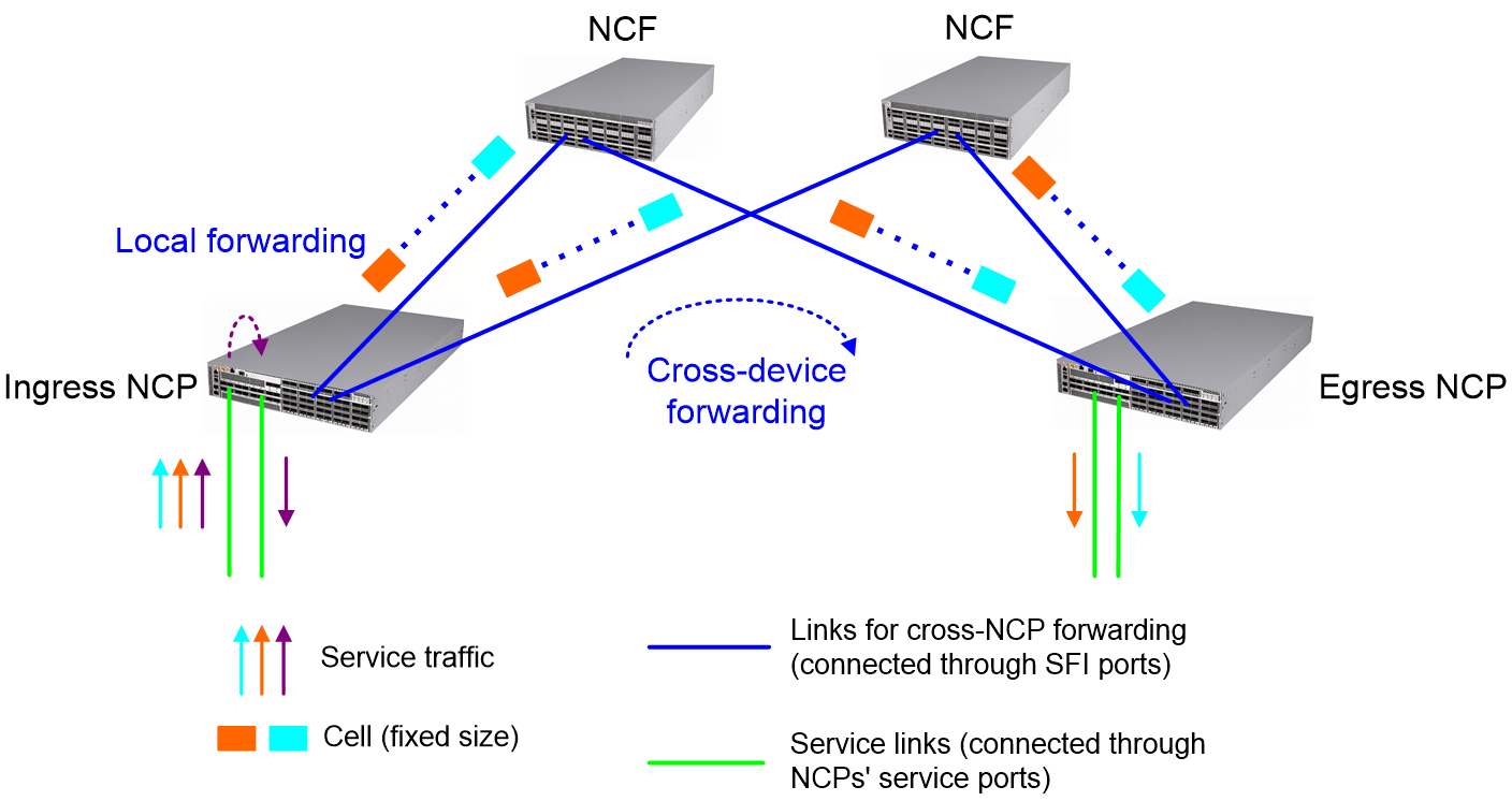
As shown in Figure 14, a DDC cloud cluster implements data forwarding as follows:
Table 1 A packet enters the DDC cloud cluster from a service interface of the ingress NCP.
4. The ingress NCP hands over the packet to its forwarding chip. The forwarding chip looks up the output interface in the FIB table, and then places the packet into the packet queue of the output interface.
¡ If the output interface is a local interface, the ingress NCP forwards the packet directly.
¡ If the output interface is located at another NCP, the ingress NCP divides the packet into cells and load-shares those cells to all NCFs connected to the egress NCP.
5. On receipt of cells, each NCF looks up topology information in the Reachability table to determine how to forward those cells.
NCPs and NCFs build a Reachability table by exchanging Reachability protocol messages. This table records the connections between NCPs and NCFs.
6. After the egress NCP receives all cells, it reassembles them into the original packet, and then forwards it through the output interface.
Technical highlights
The cell-based forwarding technology has the following advantages:
· Optimized link utilization: Cell-based forwarding reduces or avoids traffic congestion caused by uneven distribution of traffic. Unlike traditional ECMP, which might unevenly distribute a large amount of traffic across a few links, cell-based forwarding ensures that traffic is evenly distributed across all available links, regardless of the traffic size. This forwarding method improves overall network performance by reducing uneven link utilization (for example, scenarios where some links are overloaded and others remain idle).
· Less network congestion: Traffic load is distributed more evenly across links, which lowers the risk of network congestion. This is crucial for maintaining low end-to-end latency and high throughput.
· Higher DC resilience and robustness: Cell-based forwarding provides better traffic control, enabling data centers to effectively process massive traffic and traffic bursts. This enhances network stability and reliability.
VOQ-based congestion control
Application scenarios
VOQ-based congestion control is widely used in large-scale data centers, high performance computing, and big data processing, especially scenarios that require high network performance and stability.
Operating mechanism
VOQ is implemented inside a switch and keeps an independent virtual queue for each pair of input port and output port. This mechanism allows the switch to schedule traffic more precisely based on traffic destination and priority, achieving end-to-end traffic control across a switching network.
VOQ operates as follows:
1. Credit application and assignment
After the ingress NCP receives packets, it categorizes those packets, looks up the related route, and then places those packets into the virtual output queue corresponding to the target egress port. Instead of delivering those packets to the related NCF and egress NCP, the ingress NCP cooperates with the egress NCP through VOQ to identify whether bandwidth resources are sufficient.
The scheduler of the input port requests a credit from the output port to notify that some data needs to be forwarded from the egress port.
The egress NCP assigns a credit to the ingress port only if the output port has sufficient bandwidth resources.
2. Data forwarding
After the input port receives a credit, it starts forwarding packets to the output port. This process involves dividing the packets into cells and distributing those cells across all available paths.
3. Prevention of packet loss inside the DDC cloud cluster
If the output port does not have sufficient resources, it will not allocate a credit to the input port, preventing the input port from forwarding data to the output port. This avoids packet loss within the DDC cloud cluster.
Technical highlights
· Smooth data transmission: With precise traffic scheduling, VOQ minimizes the risk of traffic congestion, ensuring smooth data transmission.
· Priority-based traffic scheduling: VOQ supports priority-based traffic scheduling, ensuring that prioritized data flows are transmitted first.
· Optimized bandwidth utilization: VOQ improves the overall bandwidth utilization by avoiding traffic congestion and optimizing data transmission paths.
Accessing DDC cloud cluster
After you set up a DDC cloud cluster, you can log in to that cluster by using one of the following methods:
· Local login: Log in to the DDC cloud cluster through the console port of the active NCC.
· Remote login:
¡ Log in to the DDC cloud cluster through the management Ethernet interface of the device that hosts the master container. To use this login method, you must assign an IP address to the management Ethernet interface, and ensure that the interface and the terminal used for cluster login can reach each other. If those requirements are met, you can remotely log in to the DDC cloud cluster from the terminal via Telnet, SSH, or SNMP.
¡ Log in to the DDC cloud cluster through a service interface on any NCP. To use this login method, you must assign an IP address to the desired service interface, and ensure that the interface and the terminal used for cluster login can reach each other. If those requirements are met, you can remotely log in to the DDC cloud cluster from the terminal via Telnet, SSH, or SNMP.
No matter how you log in to the DDC cloud cluster, you actually log in to the master container, which is the configuration and control center of the DDC cloud cluster. After you configure the master container, it synchronizes the relevant settings with the standby container to ensure configuration consistency.
DDC cloud cluster HA
Data plane HA
With its unique techniques of virtualization and decoupling, the DDC cloud cluster simplifies the network and enhances rapid recovery against faults, significantly enhancing the reliability of data center networks.
· First, all NCP-NCF links in the DDC cloud cluster support automatic link aggregation. Multiple links can be used for link backup and load sharing, enhancing their reliability.
· Secondly, when a forwarding link fails in the DDC cloud cluster, the cluster can achieve rapid path convergence through hardware detection.
In traditional Spine-Leaf architecture, each router or switch acts as an independent routing entity. This practice poses challenges to the network's routing design, the scale of routing protocols, and the speed of routing convergence upon link failure.
The DDC cloud cluster is a decoupled modular device, which can be virtualized into a single routing entity. The combination of this modular device design and virtualization technology effectively simplifies the network architecture, because the entire DDC cloud cluster is counted as only one hop. This facilitates the route design and maintenance of the network, allowing for faster routing convergence and higher routing scalability.
In the DDC cloud cluster, NCPs and NCFs communicate with each other without using any dynamic routing protocol. This design uses hardware chips to monitor the connectivity of data links and thus bypass the complex routing mechanism of dynamic routing protocols, which improves system stability and response speed.
Control plane HA
Introduction
Background
In modern cloud computing environments, a stable cluster control plane is key to ensuring service continuity and reliability. Components of the control plane might fail due to hardware malfunctions, network issues, or other unforeseen events, affecting the operation of the entire cloud cluster. Therefore, an HA mechanism that can ensure a stable and nonstop control plane against these challenges is crucial for maintaining service continuity.
Function overview
The control plane HA mechanism of DDC cloud clusters offers a comprehensive solution by supporting multi-control link backup, multi-NCC backup, and container failover. This solution ensures nonstop operation of the cloud cluster in case of the failure of a control plane component.
· Control link backup: Prevents the failure of a single control link from interrupting the control plane of the DDC cloud cluster.
· Multi-NCC backup: Uses multiple NCCs for data backup. When the master container fails, the system is not affected.
· Container failover: Protects the control plane from management network failures, including NCC failure and control link failure.
Multi-control link backup
In the DDC cloud cluster, each NCP or NCF supports two IPC interfaces, and each NCC supports multiple IPC interfaces. As a best practice, connect the management switches as a ring and connect each IPC interface on an NCC, NCP, or NCF to a different management switch.
The DDC cloud cluster implements control link backup as follows:
· Under normal circumstances, all control links are available and data is transmitted correctly.
· When a link fails, traffic is steered to the backup link to ensure nonstop data transmission.
Figure 15 Control plane topology of a DDC cloud cluster
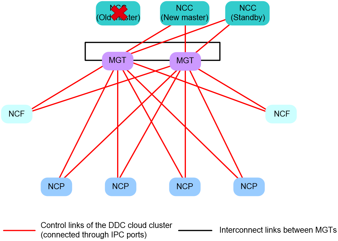
Multi-NCC backup
As a best practice, a DDC cloud cluster should contain a minimum of two NCCs to enable NCC backup. Each NCC runs a Comware container to manage the container cluster. Supported Comware container roles include Master and Standby. Each DDC cloud cluster can have only one master container, with the Comware containers on other NCCs acting as standby containers.
The DDC cloud cluster implements NCC backup as follows:
· During normal operations, the NCC hosting the master container handles all management tasks.
· If the master NCC fails, the system performs the following operations:
a. Detects the NCC failure.
b. Selects the NCC with the smallest member ID from the standby NCCs.
c. Switches the selected NCC to the new master, which then automatically takes over all management tasks.
Figure 16 Multi-NCC backup
Container failover
When the NCC does not respond in time due to a management network failure (for example, the NCC or control link fails), an NCP determines that the control plane fails and thus restarts. As a result, services are interrupted. To avoid this issue, the DDC cloud cluster offers the container failover service, which enhances the high availability of the control plane and minimizes NCP restarts.
The container failover service provides the following failover methods:
· NCP proxy: When a minority of NCPs (less than or equal to 50% of the total NCPs) are disconnected from the management network due to control link failure, NCP proxy is enabled on the other NCPs to forward control packets for those disconnected NCPs.
· Failover container: When a majority of NCPs (more than 50% of the total NCPs) are disconnected from the management network, a failover container is enabled to act as the NCC.
NCP proxy
Application scenarios
When only a few NCPs (less than or equal to 50% of the total NCPs) are disconnected from the management network and they cannot receive control packets from the NCC, the DDC cloud cluster will activate the NCP proxy function.
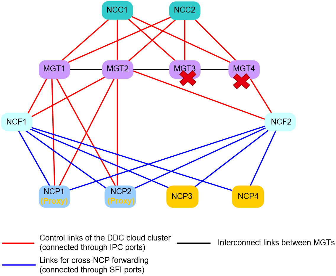
Operating mechanism
As shown in Figure 17, the DDC cloud cluster contains four NCPs. When both NCP3 and NCP4 have a control links failure and they have not received heartbeat packets from the NCCs before the timeout timer expires, the following operations will occur in the DDC cloud cluster:
1. NCP3 notifies NCP1 and NCP2 that it is disconnected from the management network.
2. NCP3 identifies that more than 50% of the NCPs in the cloud cluster are still connected to the management network and are available. Then, NCP3 selects one of the available NCPs as its proxy node (for example, NCP1), and notifies NCP1.
3. Upon receiving the notification, NCP1 activates the NCP proxy function. After that, all packets that NCP3 sends to NCC1 or NCC2 are relayed by NCP1.
4. NCP4 notifies NCP1 and NCP2 that it is disconnected from the management network.
5. NCP4 identifies that 50% of the NCPs in the cloud cluster are still connected to the management network and are available. Then, NCP3 selects one of the available NCPs as its proxy node (for example, NCP2), and notifies NCP2.
6. Upon receiving the notification, NCP2 activates the NCP proxy function. After that, all packets that NCP4 sends to NCC1 or NCC2 are relayed by NCP2.
7. NCP1 notifies NCC1 and NCC2 that it is acting as proxy for NCP3, and all packets sent to NCP3 should be forwarded through NCP1.
8. NCP2 notifies NCC1 and NCC2 that it is acting as proxy for NCP4, and all packets sent to NCP4 should be forwarded through NCP2.
|
|
NOTE: An NCP can act as proxy for only one NCP. |
Failover container
Application scenarios
During DDC cloud cluster setup, the first two NCPs that registered with the NCCs each run an additional Comware container, which acts as a failover container. When all NCCs in the DDC cloud cluster fails, a failover container is selected to take over cluster management tasks from the NCCs. Failover containers are capable of providing essential services and functions to maintain basic operations of the cloud cluster against NCC failures, ensuring the continuity and availability of the cloud cluster.
When all NCCs in the network fail or a majority of NCPs (more than 50% of the total NCPs) are disconnected from the management network, the DDC cloud cluster selects one of the failover containers as the master failover container to take over container cluster management from the NCCs. The other failover container will act as the standby (backup for the master) to provide high availability for the system.
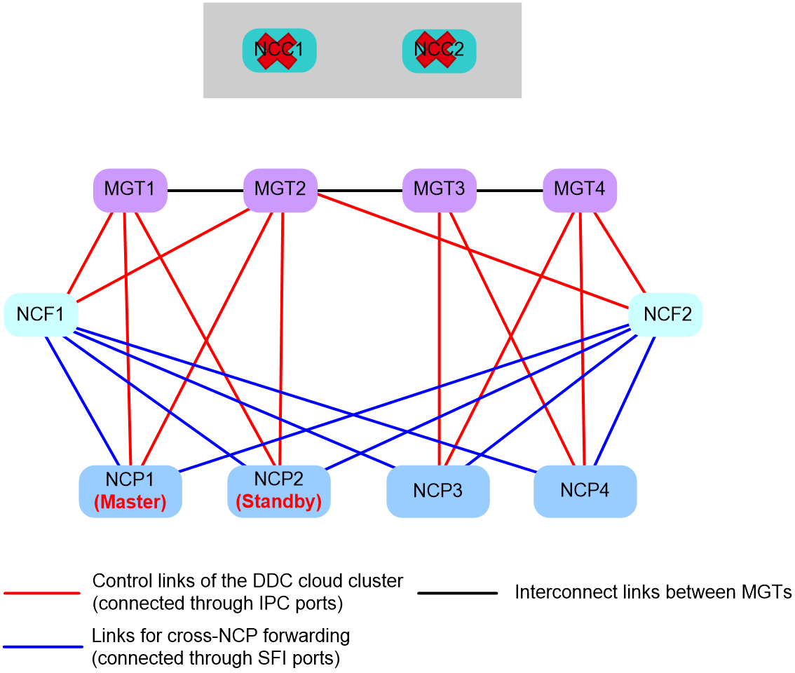
Handling mechanism in scenarios where all NCCs fail
Under normal circumstances, the master container runs on an NCC to manage the container cluster. The failover containers stay in Standby state, backing up data of the master. If all NCCs fail, one of the failover containers is elected as the new master to take over the container cluster. In this situation, NCPs and NCFs still exchange control packets over the management network, as shown in Figure 18.
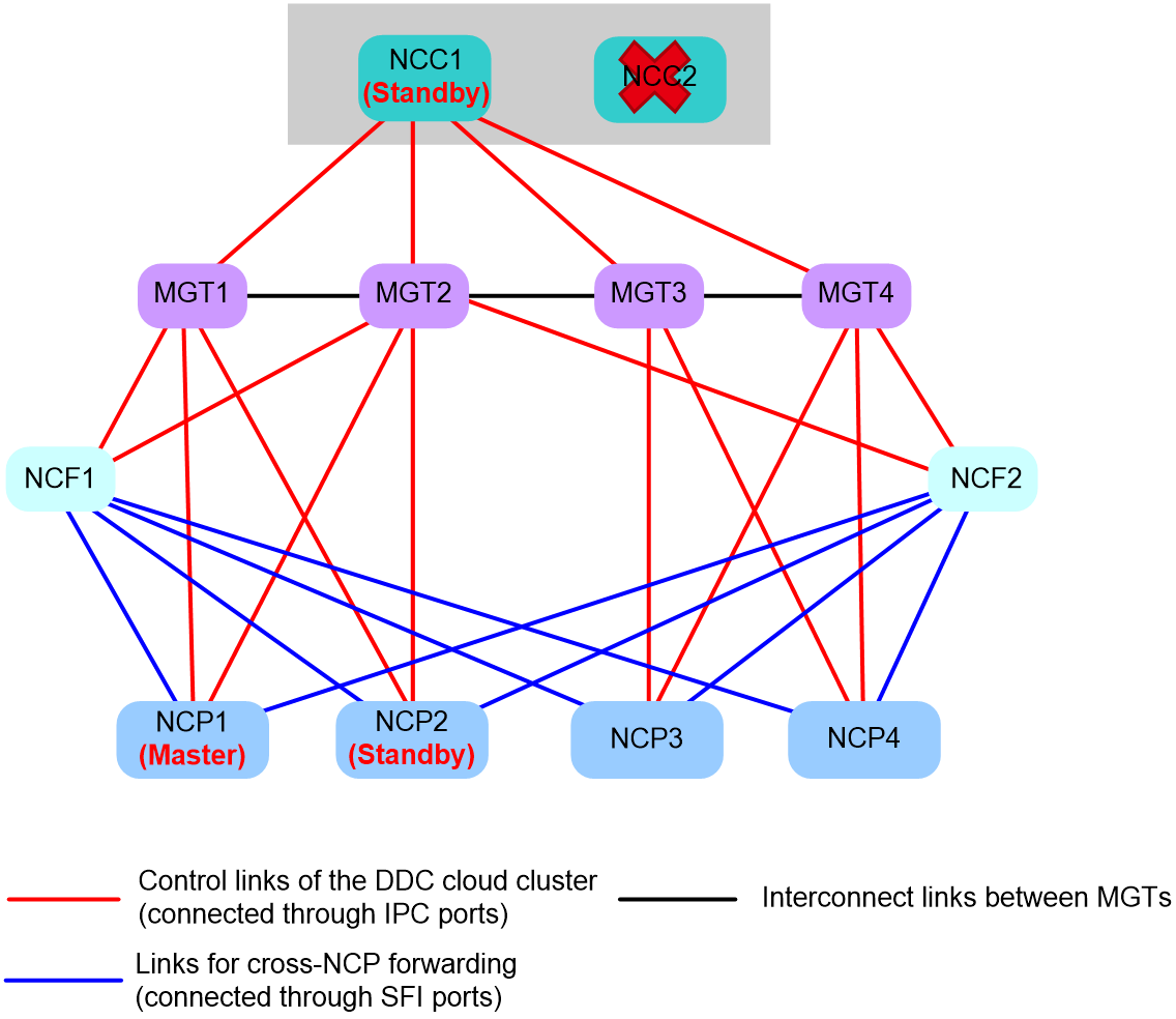
Recovery mechanism in scenarios where all NCCs fail
When an NCC in Figure 18 recover, it joins the existing container cluster as standby container. For example, if NCC1 recovers and NCC1, NCPs, and NCFs can reach each other over the management network, the following operations will occur in the cloud cluster:
1. NCC1 finds that the network has a master container (NCP1) and that container has more NCP users than NCC1. To protect the existing services on NCP1, NCC1 joins the existing container cluster as a standby, as shown in Figure 19.
2. The cloud cluster generates an SCLST_NCC_READY log message to notify the network administrator that the current master container is a failover container.
|
|
NOTE: As a best practice to ensure long-term stability of the cloud cluster, restart the master failover container after the following requirements are met: · An NCC has recovered. · The cloud cluster is running stably. To identify whether the cloud cluster is running stably, execute the display system stable command in any view, and then check the value of the System state field. If this field displays Stable, the cloud cluster is running stably. · The current services allow master container switchover. After you restart the master failover container, the container running on the NCC starts acting as the master. |
Handling mechanism in scenarios where more than 50% of the NCPs suffer from management network issues
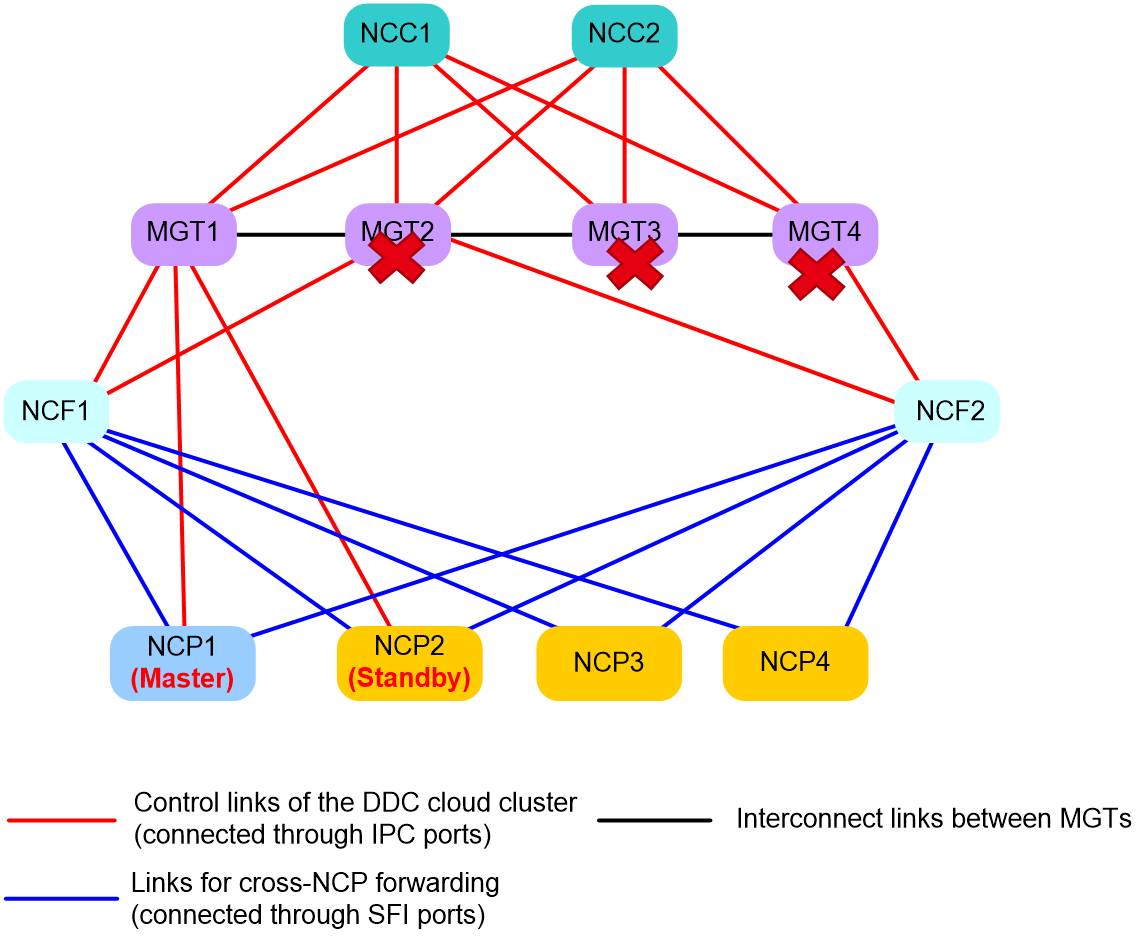
When more than 50% of the NCPs are disconnected from the management network and they cannot receive control packets from the NCCs, the cloud cluster also selects a failover container as the master container. This is because the cloud cluster do not have sufficient proxy nodes in such situation.
As shown in Figure 20, the DDC cloud cluster contains four NCPs. NCC1 and NCC2 are operating correctly. NCP2, NCP3, NCP4 all have a control link failure, and they cannot receive heartbeat packets from the NCCs until the timeout timers expires. The DDC cloud cluster handles this event as follows:
1. NCP2, NCP3, and NCP4 each notify the other NCPs that they are disconnected from the management network.
2. NCP1 and NCP2 identify that the number of NCPs disconnected from the NCCs have exceeded 50% of the total. Therefore, the two failover containers running on NCP1 and NCP2 enters the failover state, and one of them is elected as the master container to take over the container cluster.
In failover state, failover containers do not process cloud cluster protocol packets received from the NCCs. They send cloud cluster protocol packets over the data network, so the NCCs cannot not receive those cloud cluster protocol packets. Consequently, containers running on the NCPs form a container cluster, and those running on the two NCCs form another container cluster. The cloud cluster has two master containers.
3. The NCPs transmit cloud cluster protocol packets to each other through NCFs and the data network, ensuring service continuity.
Recovery mechanism in scenarios where more than 50% of the NCPs suffer from management network issues
As shown in Figure 20, if an NCP recovers from a control link failure and the other NCPs identify that no more than 50% of the NCPs are disconnected from the NCCs, the following operations will occur in the cloud cluster:
1. The NCPs determine that the management network issue has been removed, and thus exit the failover state.
2. The NCPs switch to the management network to send cloud cluster protocol packets, so the failover containers and the NCCs can receive cloud cluster protocol packets from each other.
3. The NCCs restart and join the NCPs’ container cluster as standby so as to protect the existing services on the NCPs. The dual-master issue is thus removed.
4. The cloud cluster generates an SCLST_NCC_READY log message to notify the network administrator that the current master container is a failover container.
|
|
NOTE: When the DDC cloud cluster has a dual-master issue, traffic forwarding is not affected, but management IP conflicts might occur. As a best practice to ensure long-term stability of the cloud cluster, restart the master failover container after the following requirements are met: · The cloud cluster is running stably. To identify whether the cloud cluster is running stably, execute the display system stable command in any view, and then check the value of the System state field. If this field displays Stable, the cloud cluster is running stably. · The current services allow master container switchover. After you restart the master failover container, the container running on the NCC starts acting as the master. |
Unified cloud cluster configuration management
All members in the container cluster run the Comware system. After you log in to the cloud cluster, all configurations are submitted to the master device in the container cluster for centralized processing. The master device then synchronizes the configurations to the standby devices within the container cluster. For configurations on the physical cluster, the master converts them into internal system commands, and then issues them to the physical cluster.
Configuring a container cluster involves two steps: bulk synchronization during initialization and real-time synchronization during stable operation.
Configuration synchronization in a container cluster involves the following:
· Bulk synchronization during cluster initialization
¡ When multiple devices form a container cluster, they first elect a master device. The master device starts by using its own startup configuration file. After the master device has started, it synchronizes its configuration information in bulk to all standby devices. Once the standby devices complete initialization, the container cluster is formed.
¡ Bulk synchronization is triggered when a new device attempts to join the container cluster. After the new device restarts and joins the container cluster as a standby, the master synchronizes the current configuration in bulk to the new device. The new device then completes initialization with the synchronized configuration instead of its own startup configuration file.
· Real-time synchronization during stable cluster operation
After all devices finish initialization, the container cluster operates as a single network device in the network. You can log in to any member device in the container cluster via its console port or Telnet for cluster configuration or management.
As the management hub of the container cluster, the master device is responsible for handling login requests. Regardless of the method or member device used for login, configurations are ultimately made on the master device. It synchronizes user configurations to all standby devices, ensuring configuration consistency across the cluster.
Applications of DDC cloud clusters in high performance computing
In HPC scenarios, the DDC cloud cluster employs an innovative network architecture design that makes a breakthrough from the traditional modular switch design. The flexibility and scalability of data center networks is enhanced through distributed deployment and component decoupling. This design decomposes large network switches into smaller, independent, and modular fixed-port switches, enabling distributed deployment of network functions. It also provides better cooling and power consumption control, and accommodates the demands for device upgrade and space expansion.
In addition, the virtualization technology of the DDC cloud cluster significantly enhances the performance and reliability of data centers, paving the way for future development. It also facilitates device management and operations.
The DDC cloud cluster also employs a range of efficient technologies, such as the non-blocking and low-latency forwarding architecture, VOQ, and cell-based forwarding. These technologies deliver better forwarding performance and bandwidth utilization than traditional solutions. They enable even traffic distribution across links to prevent link overload and traffic congestion arising from massive traffic processing, optimizing bandwidth utilization and overall network performance.