H3C SecPath M9000-AI-E16 NSQM5FAB16A1 Switching Fabric Module Card Manual-APW100-book.pdf(719.80 KB)
- Released At: 07-08-2022
- Page Views:
- Downloads:
- Related Documents
-
H3C SecPath M9000-AI-E16 NSQM5FAB16A1 switching fabric module
1 Identifier
The module identifier NSQM5FAB16A1 is in the upper right corner of the front panel.
2 Specifications
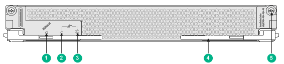
Figure 1 Front panel
|
(1) Slot status LED (RUN/ALM) |
(2) OFL LED (reserved) |
|
(3) OFL button (reserved) |
(4) Ejector lever |
|
(5) Captive screw |
|
Table 1 Module specifications
|
Item |
Specification |
|
Dimensions (H × W × D) |
39.8 × 284.4 × 520.6 mm (1.57 × 11.20 × 20.50 in) |
|
Power consumption |
83 W to 108 W |
|
Weight |
4 kg (8.82 lb) |
|
Hot swapping |
Supported |
|
Ambient temperature |
· Operating: 0°C to 45°C (32°F to 113°F) · Storage: –40°C to +70°C (–40°F to +158°F) |
|
Ambient humidity |
5%RH to 95%RH, noncondensing |
|
Compatible device model and slot |
M9000-AI-E16 multiservice security gateway (slot 10 and slot 11) |
3 LEDs
Table 2 LED description
|
LED |
Status |
Description |
|
Slot status LED (RUN/ALM) |
Flashing green |
The module is operating correctly. |
|
Steady red |
The module is faulty. |
|
|
Off |
The module is not operating. |
4 Installing and removing the module
|
|
CAUTION: Wear a reliably-grounded ESD wrist strap when installing or removing the module. |
4.1 Installing the module
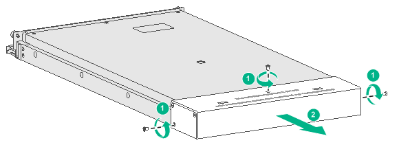
1. Place the module on the workbench and remove the metal protection box at the connector side of the module.
Figure 2 Removing the metal protection box
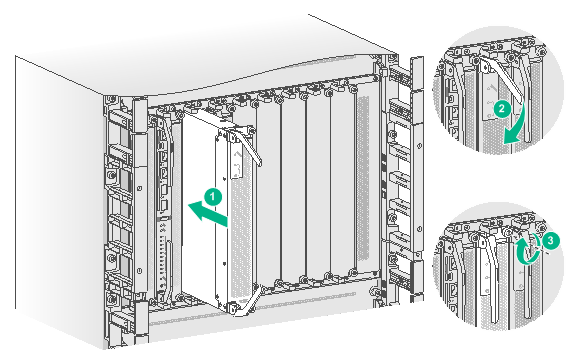
2. Face the front panel of the device. Remove the filler panel from the target slot.
3. Fully open the ejector lever and push the module slowly into the slot along the guide rails until the module is in close contact with the backplane.
4. Close the ejector levers.
5. Use a Phillips screwdriver to fasten the captive screws on the module.
Figure 3 Installing the module
4.2 Removing the module
1. Use a Phillips screwdriver to loosen the captive screws on the module until all pressure is released.
2. Simultaneously open the ejector levers on the module to separate the module from the backplane, and then pull the module slowly out of the chassis along the guide rails.
3. Install a metal protection box at the connector side of the removed module.
4. If you are not to install a new module, install a filler panel in the slot to prevent dust and ensure good ventilation.
Copyright © 2019 New H3C Technologies Co., Ltd.
The information in this document is subject to change without notice.
