H3C SecPath M9000-AI-E8 NSQM5SUP08A1 Supervisor Engine Module Card Manual-APW100-book.pdf(517.87 KB)
- Released At: 07-08-2022
- Page Views:
- Downloads:
- Related Documents
-
H3C SecPath M9000-AI-E8 NSQM5SUP08A1 supervisor engine module (MPU)
1 Identifier
The module identifier NSQM5SUP08A1 is in the upper right corner of the front panel.
2 About the module
The NSQM5SUP08A1 supervisor engine module is developed for the M9000-AI-E8 multiservice security gateway. It monitors the system status and detects abnormal commands and provides various intelligent analysis and management methods. It can enhance the security capability of the device and enable the device to deliver comprehensive and reliable security protection for users.
3 Specifications
The module has one console port, two 10/100/1000BASE-T copper management Ethernet ports, and two GE SFP fiber management Ethernet ports.
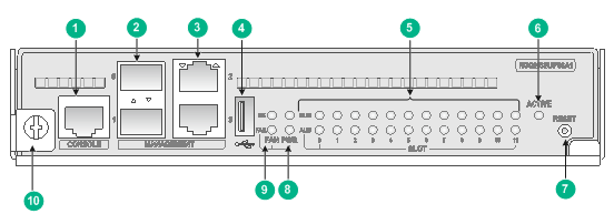
Figure 1 Front panel
|
(1) Console port (CONSOLE) |
(2) GE SFP fiber management Ethernet ports |
|
(3) 10/100/1000BASE-T copper management Ethernet ports |
|
|
(4) USB port (reserved) |
(5) Slot status LEDs |
|
(6) Active/standby status LED (ACTIVE) |
(7) Reset button (RESET) |
|
(8) Power module status LEDs |
(9) Fan tray status LEDs |
|
(10) Captive screw |
|
Table 1 Module specifications
|
Item |
Specification |
|
Flash |
1 GB |
|
Memory |
8GB (DDR3 SDRAM) |
|
Dimensions (H × W × D) |
39.8 × 200.5 × 411 mm (1.57 × 7.89 × 16.18 in) |
|
Power consumption |
46 W to 50 W |
|
Weight |
2.8 kg (6.17 lb) |
|
Hot swapping |
Supported |
|
Port |
· 1 × console port · 1 × USB port (reserved) · 4 × network management ports, including two 10/100/1000BASE-T ports and two SFP ports |
|
Ambient temperature |
· Operating: 0°C to 45°C (32°F to 113°F) · Storage: –40°C to +70°C (–40°F to +158°F) |
|
Ambient humidity |
5% RH to 95% RH, noncondensing |
|
Compatible device models and slots |
M9000-AI-E8 multiservice security gateway (slots 4 and 5) |
|
|
IMPORTANT: · To verify compatibility of the module with the software release you are using, see the release notes. · To connect a port to a management Ethernet port on the module, configure the same data rate and duplex mode for the two ports. · To upgrade the software or BootWare from BootWare, you can only use a 10/100/1000BASE-T copper management Ethernet port to transfer the software image files. |
Table 2 Console port specifications
|
Item |
Specification |
|
Connector type |
RJ-45 |
|
Interface standard |
RS-232 |
|
Transmission baud rate |
9600 bps (default) to 115200 bps |
|
Transmission medium |
Asynchronous serial cable |
|
Transmission distance |
≤ 15 m (49.21 ft) |
|
Services |
· Provides connection to an ASCII terminal. · Provides connection to the serial port of a local PC running terminal emulation program. · Supports the command line interface (CLI) |
Table 3 10/100/1000BASE-T Ethernet copper port specifications
|
Item |
Specification |
|
Connector type |
RJ-45 |
|
Interface standard |
802.3, 802.3u, and 802.3ab |
|
Interface type |
MDI/MDIX autosensing |
|
Transmission medium |
Category-5 (or above) twisted pair cable |
|
Transmission distance |
100 m (328.08 ft) |
|
Transmission rate and duplex mode |
· 10 Mbps, half/full duplex · 100 Mbps, half/full duplex · 1000 Mbps, full duplex |
Table 4 1000BASE-X SFP fiber port specifications
|
Item |
Specification |
|
Connector type |
LC |
|
Transceiver medium and maximum transmission distance |
SFP transceiver modules: see Table 5. |
|
Interface standard |
802.3, 802.3u, and 802.3ab |
|
Transmission rate and duplex mode |
1000 Mbps, full duplex |
Table 5 SFP transceiver modules available for the 1000BASE-X SFP fiber ports
|
Module |
Central wavelength |
Connector type |
Cable specifications |
Maximum transmission distance |
|
SFP-GE-SX-MM850-A |
850 nm |
LC |
50/125 µm multi-mode optical fiber (MMF) |
550 m (1804.46 ft) |
|
62.5/125 µm MMF |
275 m (902.23 ft) |
|||
|
SFP-GE-LX-SM1310-A |
1310 nm |
LC |
9/125 µm single-mode optical fiber (SMF) |
10 km (6.21 miles) |
4 LEDs
Table 6 LED description
|
LED |
Status |
Description |
|
|
10/100/1000BASE-T copper management Ethernet port LED/SFP fiber management Ethernet port LED |
Flashing |
A link is present on the port and the port is sending or receiving data. |
|
|
On |
A link is present on the port. |
||
|
Off |
No link is present on the port. |
||
|
Power module status LEDs (PWR OK and FAL) |
OK |
FAIL |
|
|
On |
Off |
All the power modules are operating correctly. |
|
|
Off |
On |
One or more power modules are faulty. |
|
|
Off |
Off |
No power is present on the device. |
|
|
FAN tray status LEDs (FAN OK and FAIL) |
OK |
FAIL |
|
|
On |
Off |
All the fan trays are operating correctly. |
|
|
Off |
On |
A fan tray is faulty, or no fan tray is present in the device. |
|
|
Off |
Off |
No power is present on the device. |
|
|
Slot status LED (SLOT RUN and ALM) |
RUN |
ALM |
|
|
Flashing (4 Hz) |
On |
The supervisor engine module, interface modules, or switching fabric module in the slot is loading software. If the LEDs remain in this state, the module software is not compatible with the device software. |
|
|
Flashing (0.5 Hz) |
Off |
The supervisor engine module, interface modules, or switching fabric module in the slot is operating correctly. |
|
|
Flashing (0.25 Hz) |
The temperature has reached the high-temperature warning threshold or dropped below the low-temperature threshold. |
||
|
On |
On |
The supervisor engine module, interface modules, or switching fabric module in the slot is starting up or is faulty. |
|
|
Off |
Off |
No supervisor engine module, interface module, or switching fabric module is present in the slot. |
|
|
Active/standby statusLED |
On |
The module is operating in active state. |
|
|
Off |
· The module is operating in standby state. · The module is faulty. (You can examine also the slot status LED for the module to determine whether a fault has occurred.) |
||
5 Installing and removing the module
|
|
CAUTION: · Wear a reliably-grounded ESD wrist strap or ESD gloves when installing or removing the module. · Do not touch the components on the module. |
5.1 Installing the module
1. Use a Phillips screwdriver to loosen the captive screws on the filler panel in the target slot and remove the filler panel.
Skip this step if the target slot does not have a filler panel.
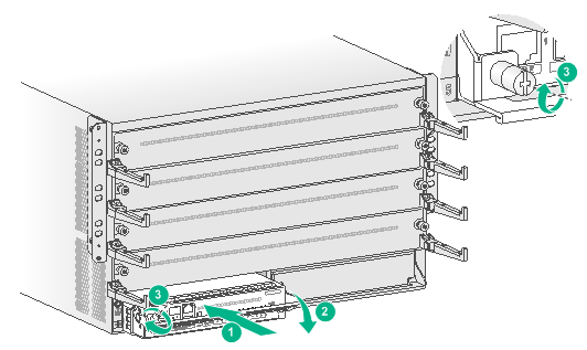
2. Align the module with the target slot.
3. Pivot up the ejector handle on the module and gently push the module into the slot along the guide rails.
4. Pivot down the ejector handle to ensure that the module is in close contact with the backplane.
5. Use a Phillips screwdriver to fasten the captive screw on the ejector handle.
Figure 2 Installing the module
5.2 Removing the module
1. Use a Phillips screwdriver to loosen the captive screw on the ejector handle until all pressure is released.
2. Pivot up the ejector handle and pull the module slowly out of the slot along the guide rails.
3. Place the module on an anti-static workbench or put it in an anti-static bag, with the component side facing up.
4. If you are not to install a new module, install a filler panel in the slot to prevent dust and ensure good ventilation in the device.
6 Software upgrade
For information about upgrading the module, see the release notes.
Copyright © 2019 New H3C Technologies Co., Ltd.
The information in this document is subject to change without notice.
