- Released At: 13-11-2022
- Page Views:
- Downloads:
- Table of Contents
- Related Documents
-
H3C RL-1U-A 1U Bottom-Support Rails Installation Guide
1 About the support rails
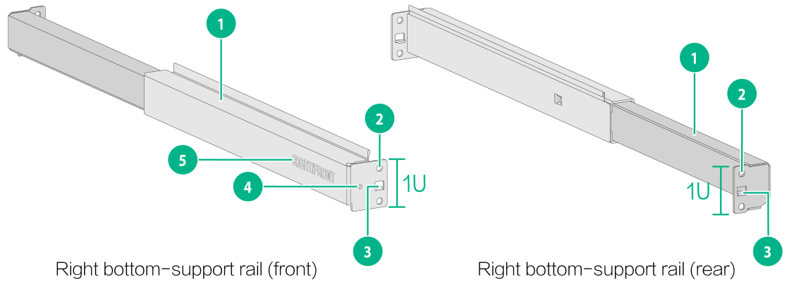
The H3C RL-1U-A 1U bottom-support rails are extendable in length. The left and right bottom-support rails are similar.
Figure 1 Right bottom-support rail
|
(1) Guide rail |
(2) Bottom-support rail installation hole |
(3) Locating tab |
|
(4) Front plate installation hole |
(5) Sign |
|
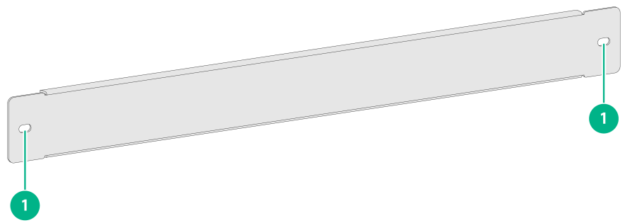
The bottom-support rails came with a front plate, as shown in Figure 2. To ensure adequate ventilation of the device, use the front plate together with the bottom-support rails.
|
(1) Installation holes |
2 Specifications
Table 1 Bottom-support rail specifications
|
Max weight bearing capacity |
Length range |
Rack space |
Compatible device models |
|
200 kg (440.92 lb) |
380 to 630 mm (14.96 to 24.80 in) |
1 RU |
· CR16000-M8 · CR16000-M16 |
When you install the bottom-support rails, follow these restrictions and guidelines:
· To attach the bottom-support rails to a rack, make sure the rack depth is in the length range of the bottom-support rails.
· Make sure the bottom-support rails have sufficient weight bearing capacity to support the device and its accessories.
3 Installation procedure
The bottom-support rails are applicable only to four-post racks.
The bottom-support rail installation might vary by rack type. The following installation procedure is for your reference only.
To install the bottom-support rails:
1. Read the signs on the bottom-support rails to avoid installation mistake.
Table 2 Description of the signs on the bottom-support rails
|
Sign |
Meaning |
Remarks |
|
FRONT/LEFT |
Front end of the left bottom-support rail |
Mount this end to the front left rack post. |
|
RIGHT/FRONT |
Front end of the right bottom-support rail |
Mount this end to the front right rack post. |
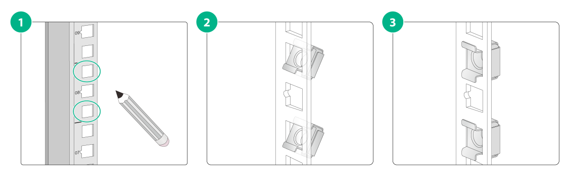
2. Mark the bottom-support rail installation positions on a rack post.
Figure 3 Installing cage nuts
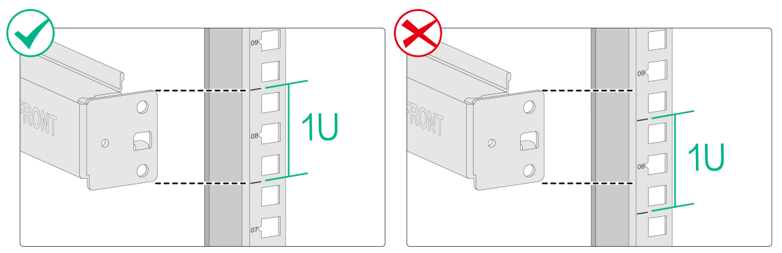
3. Make sure the bottom edge of the bottom-support rail aligns with the middle of the narrower metal area between holes in the rack post, and the locating tab aligns with the auxiliary installation hole in the rack post. See Figure 4.
|
|
NOTE: · In this document, the right bottom-support rail is installed first. · One rack unit has two standard installation holes and one auxiliary installation hole in the middle. The space between a standard installation hole and an auxiliary installation hole is larger than the space between two adjacent standard installation holes. |
Figure 4 Determining the bottom-support rail installation position on a rack post
4. Mark the square holes at the same height on the other three rack posts. You only need to mark the uppermost square holes and lowermost square holes for installation.
Install two cage nuts at a distance of 1U between them on each rack post. Make sure the corresponding cage nuts on the left and right rack posts are at the same height.
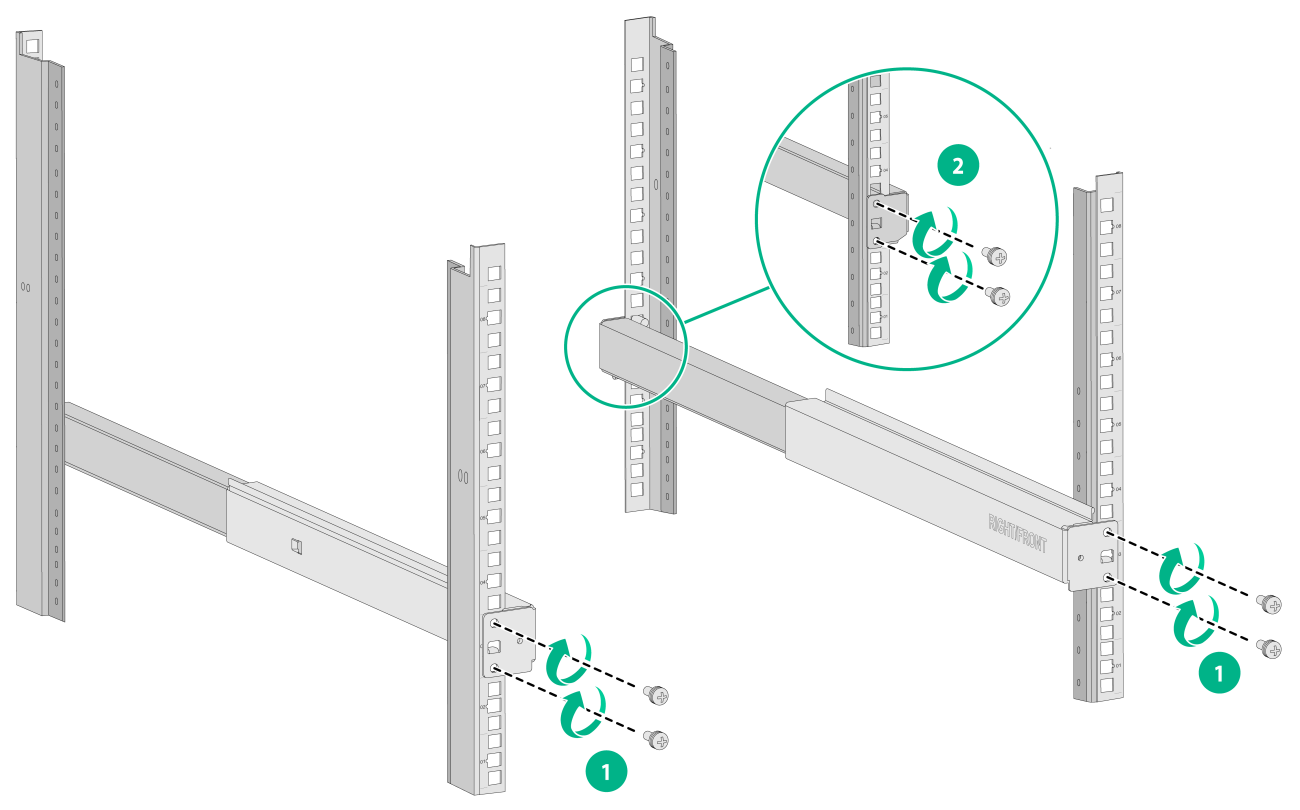
5. Align the bottom-support rail installation holes on the front end of the bottom-support rail with the cage nuts on the front rack post. Use two screws to secure the front end of the bottom-support rail to the front rack post, as shown by callout 1 in Figure 5.
6. Keep the bottom-support rail horizontally and adjust its length until the bottom-support rail installation holes on the rear end of the bottom-support rail engage the cage nuts on the rear rack post. Use two screws to secure the rear end of the bottom-support rail to the rear rack post, as shown by callout 2 in Figure 5.
7. Repeat steps 5 and 6 to install the other bottom-support rail. Make sure the two bottom-support rails are at the same height so that the device can be placed on them horizontally.
Figure 5 Using screws to secure the bottom-support rails to the rack posts
|
|
NOTE: To ensure the weight bearing capacity, make sure each installation hole in the bottom-support rails has a screw attached. |
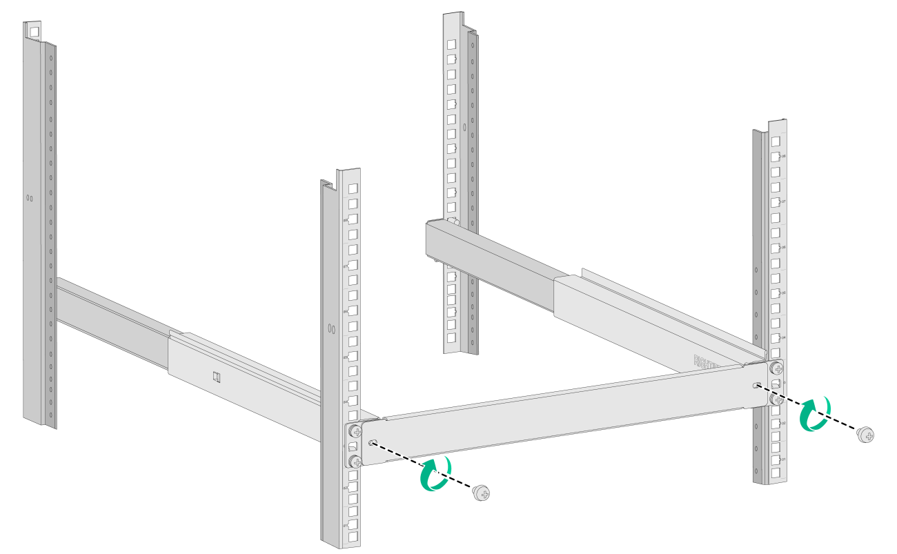
8. Attach the front plate to the bottom-support rails.
Figure 6 Attaching the front plate to the bottom-support rails
Copyright © 2022 New H3C Technologies Co., Ltd.
