- Released At: 12-12-2022
- Page Views:
- Downloads:
- Related Documents
-
|
H3C CR16000-F Router Series |
|
Universal Open Application Platform Datasheet |
|
|
|
|
Copyright © 2019 to 2022 New H3C Technologies Co., Ltd. All rights reserved.
No part of this manual may be reproduced or transmitted in any form or by any means without prior written consent of New H3C Technologies Co., Ltd.
Except for the trademarks of New H3C Technologies Co., Ltd., any trademarks that may be mentioned in this document are the property of their respective owners.
The information in this document is subject to change without notice.
Overview
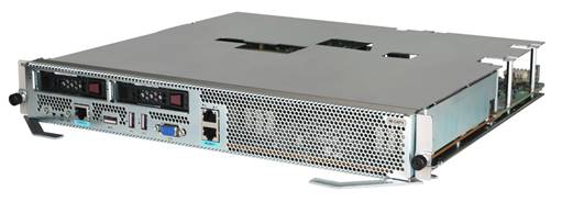
The CR16000-F routers support the IM-OAPX universal open application platform.
|
|
NOTE: For compatibility between the IM-OAPX universal open application platform and switching fabric modules, see "Appendix B FRUs and compatibility matrixes" in H3C CR16000-F Routers Installation Guide. |
Key features
IT and CT integration
IM-OAPX is an X86 module designed based on the OAA architecture. The module realizes the function of X86 general-purpose server and storage, and also provides high-speed forwarding channel and protocol interfaces to access the router system.
High-speed computing capacity
The X86 system uses Intel Xeon CPUs, enhanced DDR4 memory and large-capacity SSD drives to realize high-speed computing and storage and improve reliability.
Powerful forwarding performance
With advanced architecture and a powerful network processor, the module can perform high-speed data forwarding.
Powerful IT scalability
The X86-based system can be extended again on a Linux/Windows OS to meet various needs of users.
Specifications
The figures in this section are for illustration only.
IM-OAPX
Front panel
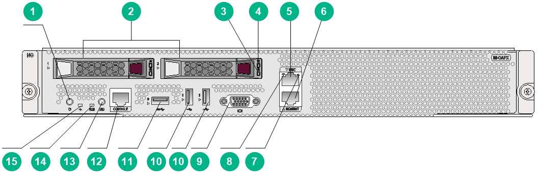
Figure 2 IM-OAPX front panel
|
(1) Power on/standby button and system power LED (see Table 1 for the LED description) |
|
(2) 2.5 inch SATA drive slot |
|
(3) Hard disk Present/Active LED (see Table 5 for the LED description) |
|
(4) Hard disk Fault/UID LED (see Table 5 for the LED description) |
|
(5) BMC network port (1 Gbps, RJ-45, default IP address 192.168.1.2/24) |
|
(6) Shared network port, which can be used as an Ethernet port (1 Gbps, RJ-45) or BMC network port (1 Gbps, RJ-45, automatically obtaining IP addresses via DHCP) |
|
(7) BMC network port status LED (see Table 6 for the LED description) |
|
(8) Shared network port status LED (see Table 7 for the LED description) |
|
(9) VGA connector |
|
(10) USB connector (USB 2.0) |
|
(11) USB connector (USB 3.0) |
|
(12) Console port |
|
(13) UID LED (see Table 4 for the LED description) |
|
(14) Run LED (see Table 3 for the LED description) |
|
(15) Health LED (see Table 2 for the LED description) |
Technical specifications
|
Item |
Specifications |
|
Dimensions (H × W × D) |
52.5 × 399 × 352 mm (2.07 × 15.71 × 13.86 in) |
|
Power consumption |
295 W to 320 W |
|
Applicable system software versions |
7751 or later |
LEDs
Table 1 System power status LED description
|
Status |
Description |
|
Steady green |
The system has started up. |
|
Flashing green (1 Hz) |
The system is starting up. |
|
Steady amber |
The system is in standby mode. |
|
Off |
No power input. |
Table 2 Health LED description
|
Status |
Description |
|
Steady green |
The system is operating correctly. |
|
Flashing green (4 Hz) |
BMC is initializing. |
|
Flashing green and yellow (1 Hz) |
A general alarm has occurred on the system, including BMC monitoring alarm and hardware alarm. |
|
Flashing yellow (1 Hz) |
A severe alarm has occurred on the system, including BMC monitoring alarm, hardware alarm, and CPU hardware abnormal alarm. |
|
Status |
Description |
|
Steady on |
The module is faulty. |
|
Off |
The module is faulty or is not installed. |
|
Normal flashing (1 Hz) |
The module is operating correctly. |
|
Fast flashing |
The module is starting up. If the LED keeps fast flashing, module registration has failed. |
|
Status |
Description |
|
Steady blue |
The UID LED is activated. The UID LED can be activated by using any of the following methods: · Press the UID button. · Turn on the UID LED via BMC. |
|
Flashing blue |
· 1 Hz—The system is being remotely managed by BMC or the firmware is being upgraded. · 4 Hz—BMC is rebooting. To reboot BMC, press UID button/LED for 8 seconds. |
|
Off |
The UID LED is not activated. |
Table 5 Hard disk LED description
|
Fault/UID LED status |
Present/Active status |
Description |
|
Flashing amber (0.5 Hz) |
Steady green /Flashing green (4 Hz) |
A hard disk failure is predicted. As a best practice, replace the hard disk before it fails. |
|
Steady amber |
Steady green /Flashing green (4 Hz) |
The hard disk is faulty. Replace the hard disk immediately. |
|
Steady blue |
Steady green /Flashing green (4 Hz) |
The hard disk is operating correctly and is selected by the RAID controller. |
|
Off |
Flashing green (4 Hz) |
The hard disk is performing a RAID migration or rebuilding, or the system is reading or writing data to the hard disk. |
|
Off |
Steady green |
The hard disk is present but no data is being read or written to the hard disk. |
|
Off |
Off |
The hard disk is not securely installed. |
Table 6 BMC network port status LED description
|
Status |
Description |
|
Steady green |
The network port is being activated. |
|
Flashing green (1 Hz) |
The network port is receiving or sending data. |
|
Off |
The network port is not connected. |
Table 7 Shared network port status LED description
|
Status |
Description |
|
Steady green |
The network port is being activated. |
|
Flashing green (1 Hz) |
The network port is receiving or sending data. |
|
Off |
The network port is not connected. |
Environment requirements
Make sure the ambient environment meets the following requirements:
· Temperature and humidity requirements
Table 8 Temperature and humidity requirements
|
Item |
Specifications |
|
Operating temperature |
0°C to 45°C (32°F to 113°F) |
|
Storage temperature |
–40°C to +70°C (–40°F to +158°F) |
|
Operating humidity |
10% RH to 95% RH, non-condensing |
|
Storage humidity |
5% RH to 95% RH, non-condensing |
· Dust protection requirements
Table 9 Dust concentration limits in the equipment room
|
Substance |
Particle diameter |
Concentration limit |
|
Dust particles |
≥ 0.5 µm |
≤ 1.8 × 10⁷ particles/m3 |
· Corrosive gas protection requirements
Table 10 Corrosive gas concentration limits in the equipment room
|
Gas |
Average concentration (mg/m3) |
Maximum concentration (mg/m3) |
|
SO2 |
0.3 |
1.0 |
|
H2S |
0.1 |
0.5 |
|
Cl2 |
0.1 |
0.3 |
|
HCI |
0.1 |
0.5 |
|
HF |
0.01 |
0.03 |
|
NH3 |
1.0 |
3.0 |
|
O3 |
0.05 |
0.1 |
|
NOX |
0.5 |
1.0 |
