- Released At: 12-12-2022
- Page Views:
- Downloads:
- Table of Contents
- Related Documents
-
|
|
|
H3C CR16000-F Series |
|
ATM Subcard Datasheet |
|
|
|
|
Copyright © 2015 to 2022 New H3C Technologies Co., Ltd. All rights reserved.
No part of this manual may be reproduced or transmitted in any form or by any means without prior written consent of New H3C Technologies Co., Ltd.
Except for the trademarks of New H3C Technologies Co., Ltd., any trademarks that may be mentioned in this document are the property of their respective owners.
The information in this document is subject to change without notice.
Contents
Overview
The following ATM subcards are available for the CR16000-F routers.
Table 1 ATM subcards available for the CR16000-F routers
|
Card model |
Description |
|
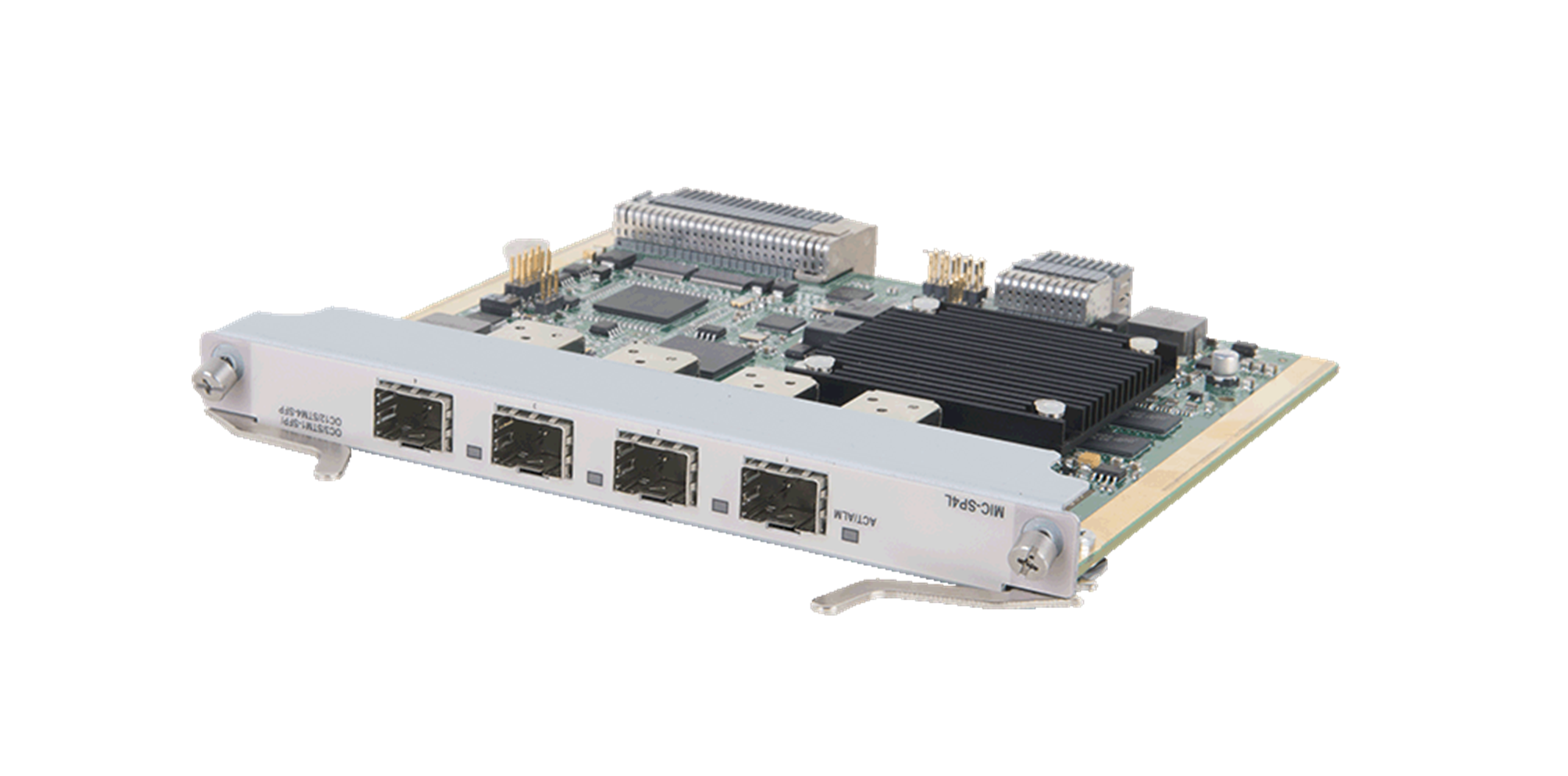
MIC-SP4L |
4-port OC-3c/STM-1c POS/ATM or 1-port OC-12c/STM-4c POS/ATM optical interface card (SFP, LC) |
Key features
Encapsulation types
The ATM interfaces support SNAP encapsulation and support the configuration of scrambling, frame format, and path trace bytes. The ATM interfaces are well compatible with devices of other mainstream manufacturers.
At ATM adaptation layer 5 (AAL5), the ATM interfaces support 2684R and 2684B encapsulation.
The ATM interfaces support the IP over ATM (IPoA). IPoA enables ATM to carry IP packets. In an IPoA implementation, ATM provides the data link layer for IP hosts in the same network. To enable IP hosts to communicate with one another over an ATM network, the IP packets they send need to be processed accordingly. IPoA makes full use of the advantage of ATM. It provides high-speed point-to-point connections and improves the bandwidth of the IP network. It also provides excellent network performance and perfect QoS services.
ATM OAM
OAM is implemented on an ATM connection as follows:
1. Each side of the connection periodically sends OAM cells to its peer.
2. After receiving an OAM cell, the recipient returns the OAM cell to the sender.
3. Each side examines the received OAM cells to see if the OAM cells are those previously sent by itself.
An ATM connection is considered normal if the round trip time of an ATM OAM cell is within a specific period. If a specific number of successive ATM OAM cells do not return within the period, the ATM connection is considered faulty.
QoS
The ATM subcards support PVC bandwidth control. Each PVC supports scheduling of eight queues.
Specifications
The figures in this section are for illustration only.
Front panel
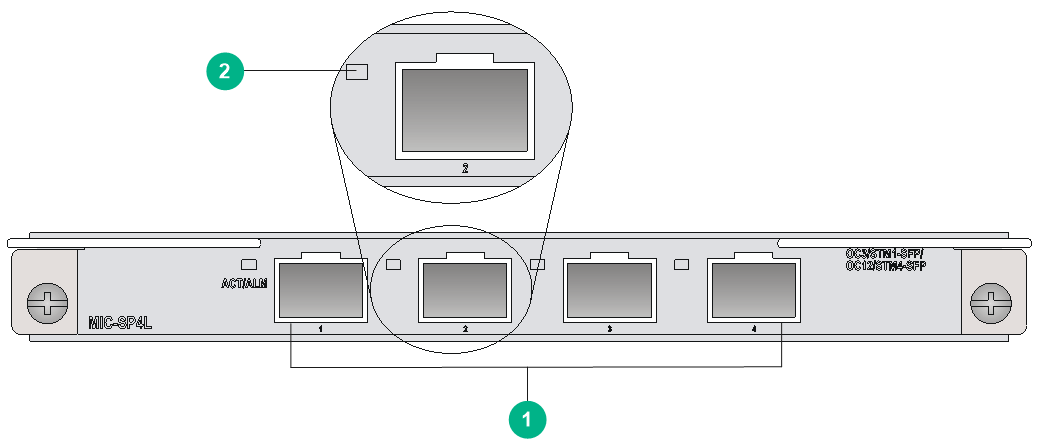
Figure 2 MIC-SP4L front panel
|
(1) OC-3c/STM-1c POS/ATM or OC-12c/STM-4c POS/ATM ports (4 in total) |
|
(2) Port status LED |
Technical specifications
|
Item |
Specifications |
|
Dimensions (H × W × D) |
18 × 165 × 142 mm (0.71 × 6.50 × 5.59 in) |
|
Power consumption |
9.6 W to 13.5 W |
|
Ports |
4 NOTE: You can configure a fiber port as an OC-3c/STM-1c POS/ATM or OC-12c/STM-4c POS/ATM fiber port at the CLI. By default, the port operates as an OC-3c/STM-1c POS fiber port.
Only port 1 can be configured as an OC-12c/STM-4c POS/ATM fiber port. |
|
Connector type |
SFP/LC |
|
Port speed |
· OC-3/STM-1 · OC-12/STM-4 |
LEDs
Table 2 POS/ATM port status LED description
|
Mark |
Status |
Description |
|
ACT/ALM |
Flashing green |
The port is sending or receiving data. |
|
Steady green |
A link is present. |
|
|
Steady red |
An alarm has occurred. |
|
|
Off |
No link is present. |
Environment requirements
Make sure the ambient environment meets the following requirements:
· Temperature and humidity requirements
Table 3 Temperature and humidity requirements
|
Item |
Specifications |
|
Operating temperature |
0°C to 45°C (32°F to 113°F) |
|
Storage temperature |
–40°C to +70°C (–40°F to +158°F) |
|
Operating humidity |
10% RH to 95% RH, non-condensing |
|
Storage humidity |
5% RH to 95% RH, non-condensing |
· Dust protection requirements
Table 4 Dust concentration limits in the equipment room
|
Substance |
Particle diameter |
Concentration limit |
|
Dust particles |
≥ 0.5 µm |
≤ 1.8 × 10⁷ particles/m3 |
· Corrosive gas protection requirements
Table 5 Corrosive gas concentration limits in the equipment room
|
Gas |
Average concentration (mg/m3) |
Maximum concentration (mg/m3) |
|
SO2 |
0.3 |
1.0 |
|
H2S |
0.1 |
0.5 |
|
Cl2 |
0.1 |
0.3 |
|
HCI |
0.1 |
0.5 |
|
HF |
0.01 |
0.03 |
|
NH3 |
1.0 |
3.0 |
|
O3 |
0.05 |
0.1 |
|
NOX |
0.5 |
1.0 |
