- Released At: 12-12-2022
- Page Views:
- Downloads:
- Related Documents
-
|
|
|
H3C CR16000-F Router Series |
|
100G Ethernet Optical Interface Module Datasheet |
|
|
|
|
Copyright © 2015 to 2022 New H3C Technologies Co., Ltd. All rights reserved.
No part of this manual may be reproduced or transmitted in any form or by any means without prior written consent of New H3C Technologies Co., Ltd.
Except for the trademarks of New H3C Technologies Co., Ltd., any trademarks that may be mentioned in this document are the property of their respective owners.
The information in this document is subject to change without notice.
Contents
Overview
The following 100G Ethernet optical interface modules are available for the CR16000-F routers.
Table 1 100G Ethernet optical interface modules available for the routers
|
Module model |
Description |
|
CSPC-CP1LCX |
1-Port 100GBASE Ethernet optical interface module (CFP, LC) (C Type) |
|
CSPC-CP2LB |
2-Port 100GBASE Ethernet optical interface module (CFP, LC) (B Type) |
|
|
NOTE: For compatibility between 100G Ethernet optical interface modules and switching fabric modules, see Appendix B FRUs and compatibility matrixes in H3C CR16000-F Routers Installation Guide. |
Key features
High-speed access rate
The interface modules use 100GE CFP transceiver modules to provide an access rate of 100 Gbps per port, meeting data rate requirements for data centers.
High performance and scalability
With high-speed CPUs, the interface modules greatly improve the service processing capability and provide independent OAM engine for link status monitoring.
Environment-friendly design
The interface modules are compliant with the Restriction of Hazardous Substances (RoHS) standard.
Hot swapping
The interface modules are hot swappable. Installing and removing such a module on an operating router does not affect ongoing services on other modules. The management system monitors the module in real time and implements automated configuration for the module to ensure service continuity.
Specifications
The figures in this section are for illustration only.
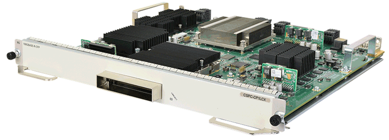
CSPC-CP1LCX
Figure 1 CSPC-CP1LCX
Front panel
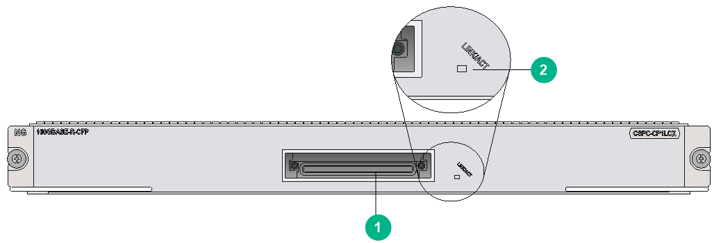
Figure 2 CSPC-CP1LCX front panel
|
(1) 100GBASE-R-CFP fiber port (1 in total) |
(2) CFP port status LED |
Technical specifications
|
Item |
Specifications |
|
Dimensions (H × W × D) |
40 × 399 × 352 mm (1.57 ×15.7 × 13.86 in) |
|
Power consumption |
115 W to 173 W |
|
Ports |
1 |
|
Connector type |
LC |
|
Port speed |
100 Gbps |
|
Net weight |
3.5 kg (7.72 lb) |
|
System software version |
7133 or later |
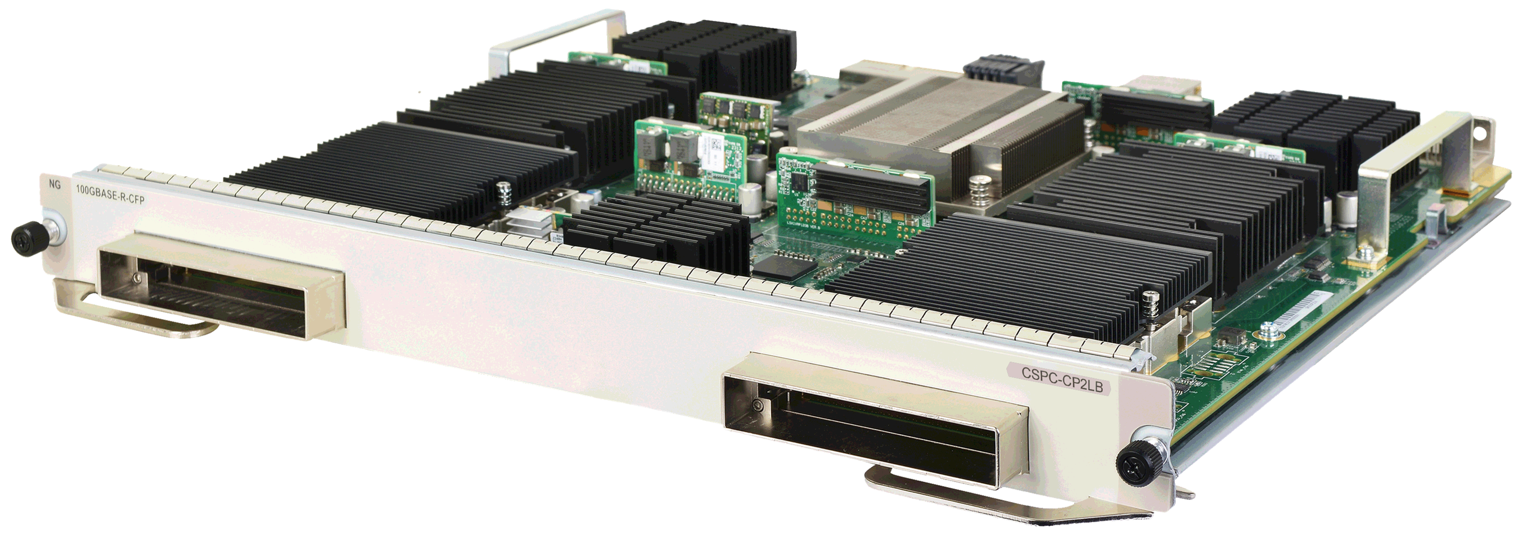
CSPC-CP2LB
Figure 3 CSPC-CP2LB
Front panel
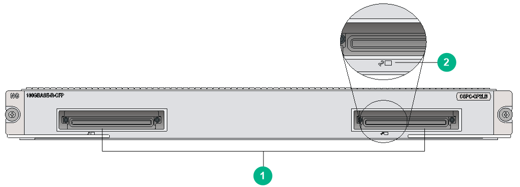
Figure 4 CSPC-CP2LB front panel
|
(1) 100GBASE-R-CFP fiber ports (2 in total) |
(2) CFP port status LED |
Technical specifications
|
Item |
Specifications |
|
Dimensions (H × W × D) |
40 × 399 ×352 mm (1.57 ×15.7 × 13.86 in) |
|
Power consumption |
150 W to 197 W |
|
Ports |
2 |
|
Connector type |
LC |
|
Port speed |
100 Gbps |
|
Net weight |
4.06 kg (8.95 lb) |
|
System software version |
7133 or later |
LEDs
Table 2 CFP port status LED description
|
Status |
Description |
|
Flashing |
The port is receiving or transmitting data. |
|
On |
A link is present. |
|
Off |
No link is present. |
Environment requirements
Make sure the ambient environment meets the following requirements:
· Temperature and humidity requirements
Table 3 Temperature and humidity requirements
|
Item |
Specifications |
|
Operating temperature |
0°C to 45°C (32°F to 113°F) |
|
Storage temperature |
–40°C to +70°C (–40°F to +158°F) |
|
Operating humidity |
10% RH to 95% RH, non-condensing |
|
Storage humidity |
5% RH to 95% RH, non-condensing |
· Dust protection requirements
Table 4 Dust concentration limits in the equipment room
|
Substance |
Particle diameter |
Concentration limit |
|
Dust particles |
≥ 0.5 µm |
≤ 1.8 × 10⁷ particles/m3 |
· Corrosive gas protection requirements
Table 5 Corrosive gas concentration limits in the equipment room
|
Gas |
Average concentration (mg/m3) |
Maximum concentration (mg/m3) |
|
SO2 |
0.3 |
1.0 |
|
H2S |
0.1 |
0.5 |
|
Cl2 |
0.1 |
0.3 |
|
HCI |
0.1 |
0.5 |
|
HF |
0.01 |
0.03 |
|
NH3 |
1.0 |
3.0 |
|
O3 |
0.05 |
0.1 |
|
NOX |
0.5 |
1.0 |
