- Released At: 16-10-2023
- Page Views:
- Downloads:
- Table of Contents
- Related Documents
-
|
|
|
IPsec Technology White Paper |
|
|
|
|
|
|
Copyright © 2022 New H3C Technologies Co., Ltd. All rights reserved.
No part of this manual may be reproduced or transmitted in any form or by any means without prior written consent of New H3C Technologies Co., Ltd.
Except for the trademarks of New H3C Technologies Co., Ltd., any trademarks that may be mentioned in this document are the property of their respective owners.
The information in this document is subject to change without notice.
Contents
Relationship between IPsec and IKE
IPsec SA setup through IKEv1 negotiation
Hardware crypto engine with high security and efficiency
Quantum encryption with high security
IPv6 routing protocol-based IPsec
Netmask filtering and flow overlap check
Peer address backup and switchback
Flexible encapsulation protocol switching
Remote access from mobile users
IPsec in multiple VPN instances
Overview
Technical background
With the rapid development of Internet technology, more and more enterprises choose the Internet for information exchange. However, data transmission security cannot be guaranteed because the IP protocol cannot ensure security and networks have many security threats and data leakage risks.
IP Security (IPsec) is defined by the IETF to provide transparent security services for IP communications. It operates at the IP layer and transmits data in a secure channel established between two endpoints (such as two security gateways). Such a secure channel is usually called an IPsec tunnel.
Benefits
IPsec provides the following benefits:
· Confidentiality—The sender encrypts packets before transmitting them over the Internet, protecting the packets from being eavesdropped en route.
· Data integrity—The receiver verifies the hash values of the packets received from the sender to make sure they are not tampered with during transmission.
· Data origin authentication—The receiver verifies the digital signature of the packets to identify the authenticity of the sender.
· Good compatibility—IPsec is applicable to all IP-based data transmission without modifying any original packets.
· Support for IKE—IKE provides automatic key negotiation and simplifies IPsec configuration.
· Anti-replay—IPsec supports encryption on a per-packet and supports anti-reply to prevent attacks.
IPsec implementation
Concepts
IPsec includes the following basic concepts: Security association, security protocols, security mechanism, and encapsulation modes.
Security association
About security association
A security association (SA) is an agreement negotiated between two communicating parties called IPsec peers. An SA includes the following parameters for data protection:
· Security protocols (AH, ESP, or both).
· Encapsulation mode (transport mode or tunnel mode).
· Authentication algorithm (HMAC-MD5, SM3, or HMAC-SHA1).
· Encryption algorithm (DES, 3DES, SM, or AES).
· Shared keys and their lifetimes.
An SA is unidirectional. At least two SAs are needed to protect data flows in a bidirectional communication. If two peers want to use both AH and ESP to protect data flows between them, they construct an independent SA for each protocol in each direction.
An SA is uniquely identified by a triplet, which consists of the security parameter index (SPI), destination IP address, and security protocol identifier. An SPI is a 32-bit number. It is transmitted in the AH/ESP header.
SA setup
An SA can be set up in the following modes:
· Manual mode—Configure all parameters for the SA through commands. This configuration mode is complex and does not support some advanced features (such as periodic key update), but it can implement IPsec without IKE. This mode is mainly used in small and static networks or when the number of IPsec peers in the network is small.
· IKE negotiation mode—The peers negotiate and maintain the SA through IKE. This configuration mode is simple and has good expansibility. As a best practice, set up SAs through IKE negotiations in medium- and large-scale dynamic networks.
SA aging
A manually configured SA never ages out.
An IKE-created SA has a lifetime and will be deleted when its lifetime timer expires.
Before the SA lifetime timer expires, IKE negotiates a new SA, which takes over immediately after its creation. The interval from the creation of an SA to the negotiation of a new SA is the SA's soft lifetime.
The SA soft lifetime is calculated as follows: SA soft lifetime = SA lifetime – SA soft lifetime buffer. If the SA soft lifetime buffer is not configured, the system calculates a default SA soft lifetime based on the SA lifetime.
The lifetime of an IKE-created SA comes in two types:
· Time-based lifetime—Defines how long the SA can exist after it is created.
· Traffic-based lifetime—Defines the maximum traffic that the SA can process.
If both lifetime timers are configured for an SA, the SA is deleted when either of the lifetime timers expires.
Security protocols
IPsec is a security framework that has the following protocols and algorithms:
· Authentication Header (AH).
· Encapsulating Security Payload (ESP).
· Internet Key Exchange (IKE).
· Algorithms for authentication and encryption.
AH and ESP are security protocols that provide security services with different encapsulation modes. IKE performs automatic key exchange.
IPsec comes with two security protocols, AH and ESP. They define how to encapsulate IP packets and the security services that they can provide.
· AH (protocol 51) defines the encapsulation of the AH header in an IP packet. AH can provide data origin authentication, data integrity, and anti-replay services to prevent data tampering, but it cannot prevent eavesdropping. Therefore, it is suitable for transmitting non-confidential data. Authentication algorithms supported by AH include HMAC-MD5 and HMAC-SHA1. AH does not support NAT traversal.
· ESP (protocol 50) defines the encapsulation of the ESP header and trailer in an IP packet. ESP can provide data encryption, data origin authentication, data integrity, and anti-replay services. Unlike AH, ESP can guarantee data confidentiality because it can encrypt the data before encapsulating the data to IP packets. ESP-supported encryption algorithms include DES, 3DES, and AES, and authentication algorithms include HMAC-MD5 and HMAC-SHA1.
Both AH and ESP provide authentication services, but AH performs authentication on the entire IP packets, while ESP performs authentication only on the payload part of IP packets. The authentication service provided by AH is stronger. In practice, you can choose either or both security protocols. When both AH and ESP are used, an IP packet is encapsulated first by ESP and then by AH.
Security mechanism
Authentication algorithms
IPsec uses hash algorithms to perform authentication. A hash algorithm produces a fixed-length digest for an arbitrary-length message. IPsec peers respectively calculate message digests for each packet. The receiver compares the local digest with that received from the sender. If the digests are identical, the receiver considers the packet intact and the sender's identity valid. IPsec supports the following types of authentication algorithms:
· Hash-based Message Authentication Code (HMAC) based authentication algorithms, including HMAC-MD5 and HMAC-SHA.
HMAC-MD5 is faster but less secure than HMAC-SHA.
· SM3 authentication algorithms.
Encryption algorithms
IPsec uses symmetric encryption algorithms, which encrypt and decrypt data by using the same keys. The following encryption algorithms are available for IPsec on the device:
· DES—Encrypts a 64-bit plaintext block with a 56-bit key. DES is the least secure but the fastest algorithm.
· 3DES—Encrypts plaintext data with three 56-bit DES keys. The key length totals up to 168 bits. It provides moderate security strength and is slower than DES.
· AES—Encrypts plaintext data with a 128-bit, 192-bit, or 256-bit key. AES provides the highest security strength and is slower than 3DES.
· SM—Encrypts plaintext data with a 128-bit key. SM provides the same level of security strength as AES.
Key exchange algorithm
The DH algorithm is a public key algorithm. With this algorithm, two peers can exchange keying material and then use the material to calculate the shared keys. Due to the decryption complexity, a third party cannot decrypt the keys even after intercepting all keying materials.
Encapsulation modes
IPsec supports the following encapsulation modes: transport mode and tunnel mode.
Transport mode
The security protocols protect the upper layer data of an IP packet. Only the transport layer data is used to calculate the security protocol headers. The calculated security protocol headers and the encrypted data (only for ESP encapsulation) are placed after the original IP header. You can use the transport mode when end-to-end security protection is required (the secured transmission start and end points are the actual start and end points of the data). The transport mode is typically used for protecting host-to-host communications, as shown in Figure 1.
Figure 1 IPsec protection in transport mode

Tunnel mode
The security protocols protect the entire IP packet. The entire IP packet is used to calculate the security protocol headers. The calculated security protocol headers and the encrypted data (only for ESP encapsulation) are encapsulated in a new IP packet. In this mode, the encapsulated packet has two IP headers. The inner IP header is the original IP header. The outer IP header is added by the network device that provides the IPsec service. You must use the tunnel mode when the secured transmission start and end points are not the actual start and end points of the data packets (for example, when two gateways provide IPsec but the data start and end points are two hosts behind the gateways). The tunnel mode is typically used for protecting gateway-to-gateway communications, as shown in Figure 2.
Figure 2 IPsec protection in tunnel mode

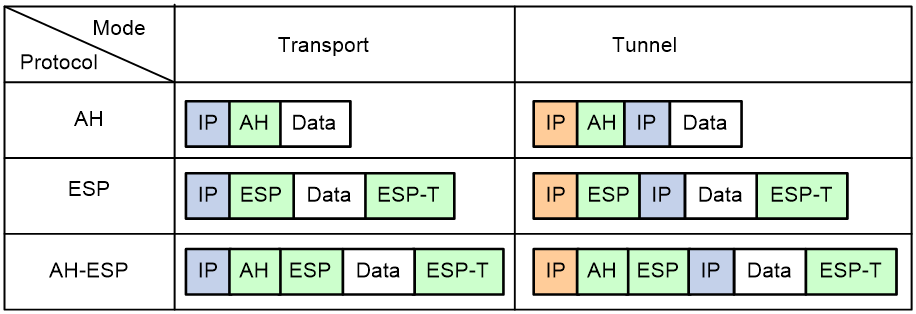
Figure 3 shows how the security protocols encapsulate an IP packet in different encapsulation modes.
Figure 3 Security protocol encapsulations in different modes
IKE
Benefits of IKE
IKE provides the following benefits for IPsec:
· Automatically negotiates IPsec parameters.
· Performs DH exchanges to calculate shared keys, making sure each SA has a key that is independent of other keys.
· Automatically negotiates SAs when the sequence number in the AH or ESP header overflows, making sure IPsec can provide the anti-replay service by using the sequence number.
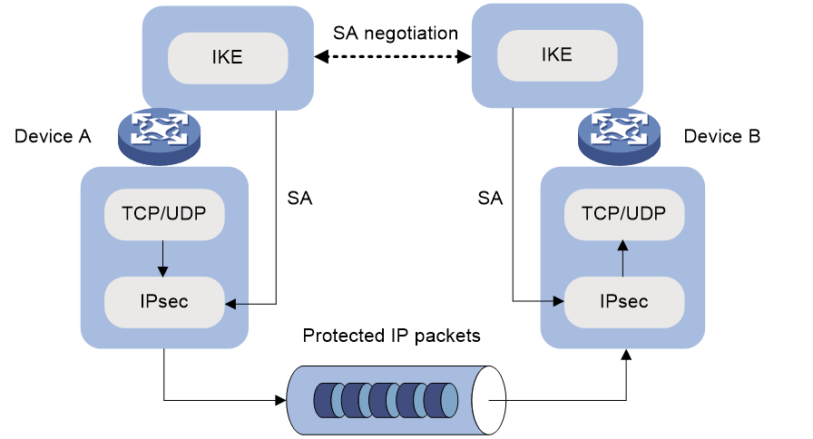
Relationship between IPsec and IKE
As shown in Figure 4, IKE negotiates SAs for IPsec and transfers the SAs to IPsec, and IPsec uses the SAs to protect IP packets.
Figure 4 Relationship between IKE and IPsec
IKE security mechanism
IKE has a series of self-protection mechanisms and supports secure identity authentication, key distribution, and IPsec SA establishment on insecure networks.
Identity authentication
The IKE identity authentication mechanism is used to authenticate the identity of the communicating peers. The device supports the following identity authentication methods:
· Preshared key authentication—Two communicating peers use the pre-configured shared key for identity authentication.
· RSA signature authentication and DSA signature authentication—Two communicating peers use the digital certificates issued by the CA for identity authentication.
DH algorithm
The DH algorithm is a public key algorithm. With this algorithm, two peers can exchange keying material and then use the material to calculate the shared keys. Due to the decryption complexity, a third party cannot decrypt the keys even after intercepting all keying materials.
PFS
The Perfect Forward Secrecy (PFS) feature is a security feature based on the DH algorithm. After PFS is enabled, an additional DH exchange is performed in IKE phase 2 to make sure IPsec keys have no derivative relations with IKE keys and a broken key brings no threats to other keys
IKE versions
IKEv1
Built on a framework defined by ISAKMP, Internet Key Exchange version 1 (IKEv1) provides automatic key negotiation and SA establishment services for IPsec.
IKEv2
Internet Key Exchange version 2 (IKEv2) is an enhanced version of IKEv1. The same as IKEv1, IKEv2 has a set of self-protection mechanisms and can be used on insecure networks for reliable identity authentication, key distribution, and IPsec SA negotiation.
Difference between IKEv1 and IKEv2
Compared with IKEv1, IKEv2 provides stronger protection against attacks and higher key exchange ability and needs fewer message exchanges.
IPsec SA setup through IKEv1 negotiation
IKEv1 negotiation process
Basic process
IKE negotiates keys and SAs for IPsec in two phases:
1. Phase 1—The two peers establish an IKE SA, a secure, authenticated channel for communication.
2. Phase 2—Using the IKE SA established in phase 1, the two peers negotiate to establish IPsec SAs.
Negotiation mode
The available IKE negotiation modes for phase 1 include the following:
· Main mode.
· Aggressive mode.
· GM main mode.
IKE exchange process in main mode
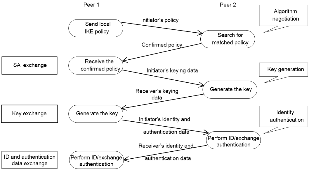
As shown in Figure 5, the main mode of IKE negotiation in phase 1 involves three pairs of messages:
· SA exchange—Used for negotiating the IKE security policy.
· Key exchange—Used for exchanging the DH public value and other values, such as the random number. The two peers use the exchanged data to generate key data and use the encryption key and authentication key to ensure the security of IP packets.
· ID and authentication data exchange—Used for identity authentication.
Figure 5 IKE exchange process in main mode
IKE exchange process in aggressive mode
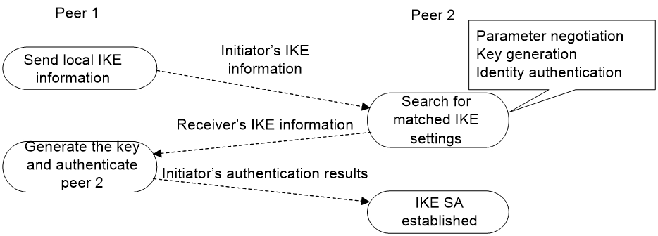
As shown in Figure 6, the process of phase 1 IKE negotiation in aggressive mode is as follows:
1. The initiator (peer 1) sends a message containing the local IKE information to peer 2. The message includes parameters used for IKE SA establishment, keying data, and peer 1's identity information.
2. Peer 2 chooses the IKE establishment parameters to use, generate the key, and authenticate peer 1's identity. Then it sends the IKE data to peer 1.
3. Peer 1 generates the key, authenticates peer 2's identity, and sends the results to peer 1.
After the preceding process, an IKE SA is established between peer 1 and peer 2.
The aggressive mode is faster than the main mode but it does not provide identity information protection. The main mode provides identity information protection but is slower. Choose the appropriate negotiation mode according to your requirements.
Figure 6 IKE exchange process in aggressive mode
IKE exchange process in GM main mode
The IKE exchange process in GM main mode is similar to that in main mode.
If the local end uses the GM main mode, the two IKE peers must use the RSA-DE or SM2-DE digital envelope authentication method for user authentication.
IPsec SA setup through IKEv2
IKEv2 negotiation process
Compared with IKEv1, IKEv2 simplifies the negotiation process and is much more efficient. For IKEv1 to set up one IKE SA and one pair of IPsec SAs, it must go through two phases that use a minimum of six messages. IKEv2 can set up one IKE SA and one pair of IPsec SAs by using four messages through two exchanges. To set up one more pair of IPsec SAs, IKEv2 uses only one exchange with two messages.
IKEv2 defines three types of exchanges as follows:
· Initial exchanges—Negotiates one IKE SA and one pair of IPsec SAs with four messages.
· CREATE_CHILD_SA exchange—Allows IKEv2 to set up one more pair of IPsec SAs within the IKE SA after the four-message initial exchanges. IKEv2 also uses the CREATE_CHILD_SA exchange to rekey IKE SAs and Child SAs.
· INFORMATIONAL exchange—Conveys control messages about errors and notifications.
As shown in Figure 7, IKEv2 uses two exchanges during the initial exchange process: IKE_SA_INIT and IKE_AUTH, each with two messages.
· IKE_SA_INIT exchange—Negotiates IKE SA parameters and exchanges keys.
· IKE_AUTH exchange—Authenticates the identity of the peer and establishes IPsec SAs.
After the four-message initial exchanges, IKEv2 sets up one IKE SA and one pair of IPsec SAs.
Figure 7 IKEv2 Initial exchange process

New features in IKEv2
DH guessing
In the IKE_SA_INIT exchange, the initiator guesses the DH group that the responder is most likely to use and sends it in an IKE_SA_INIT request message. If the initiator's guess is correct, the responder responds with an IKE_SA_INIT response message and the IKE_SA_INIT exchange is finished. If the guess is wrong, the responder responds with an INVALID_KE_PAYLOAD message that contains the DH group that it wants to use. The initiator then uses the DH group selected by the responder to reinitiate the IKE_SA_INIT exchange.
The DH guessing mechanism allows for more flexible DH group configuration and enables the initiator to adapt to different responders.
Cookie challenging
During IKEv2 initial exchanges, messages for the IKE_SA_INIT exchange are in plain text, which might be tampered. An IKEv1 responder cannot confirm the validity of the initiators and must maintain half-open IKE SAs, which makes the responder susceptible to DoS attacks. An attacker can send a large number of IKE_SA_INIT requests with forged source IP addresses to the responder, exhausting the responder's system resources.
IKEv2 introduces the cookie challenging mechanism to prevent such DoS attacks. When an IKEv2 responder maintains a threshold number of half-open IKE SAs, it starts the cookie challenging mechanism. The responder generates a cookie and includes it in the response sent to the initiator. If the initiator initiates a new IKE_SA_INIT request that carries the correct cookie, the responder considers the initiator valid and proceeds with the negotiation. If the carried cookie is incorrect, the responder terminates the negotiation.
The cookie challenging mechanism automatically stops working when the number of half-open IKE SAs drops below the threshold.
IKEv2 SA rekeying
For security purposes, both IKE SAs and IPsec SAs have a lifetime and must be rekeyed when the lifetime expires. An IKEv1 SA lifetime is negotiated. An IKEv2 SA lifetime, in contrast, is configured. If two peers are configured with different lifetimes, the peer with the shorter lifetime always initiates the SA rekeying. This mechanism reduces the possibility that two peers will simultaneously initiate a rekeying. Simultaneous rekeying results in redundant SAs and SA status inconsistency on the two peers.
IKEv2 message retransmission
Unlike IKEv1 messages, for IKEv2, all messages sent by an initiator must be confirmed by the responder, thus increasing reliability. IKEv2 messages appear in request/response pairs. IKEv2 uses the Message ID field in the message header to identify the request/response pair. If an initiator sends a request but receives no response with the same Message ID value within a specific period of time, the initiator retransmits the request.
It is always the IKEv2 initiator that initiates the retransmission, and the retransmitted message must use the same Message ID value.
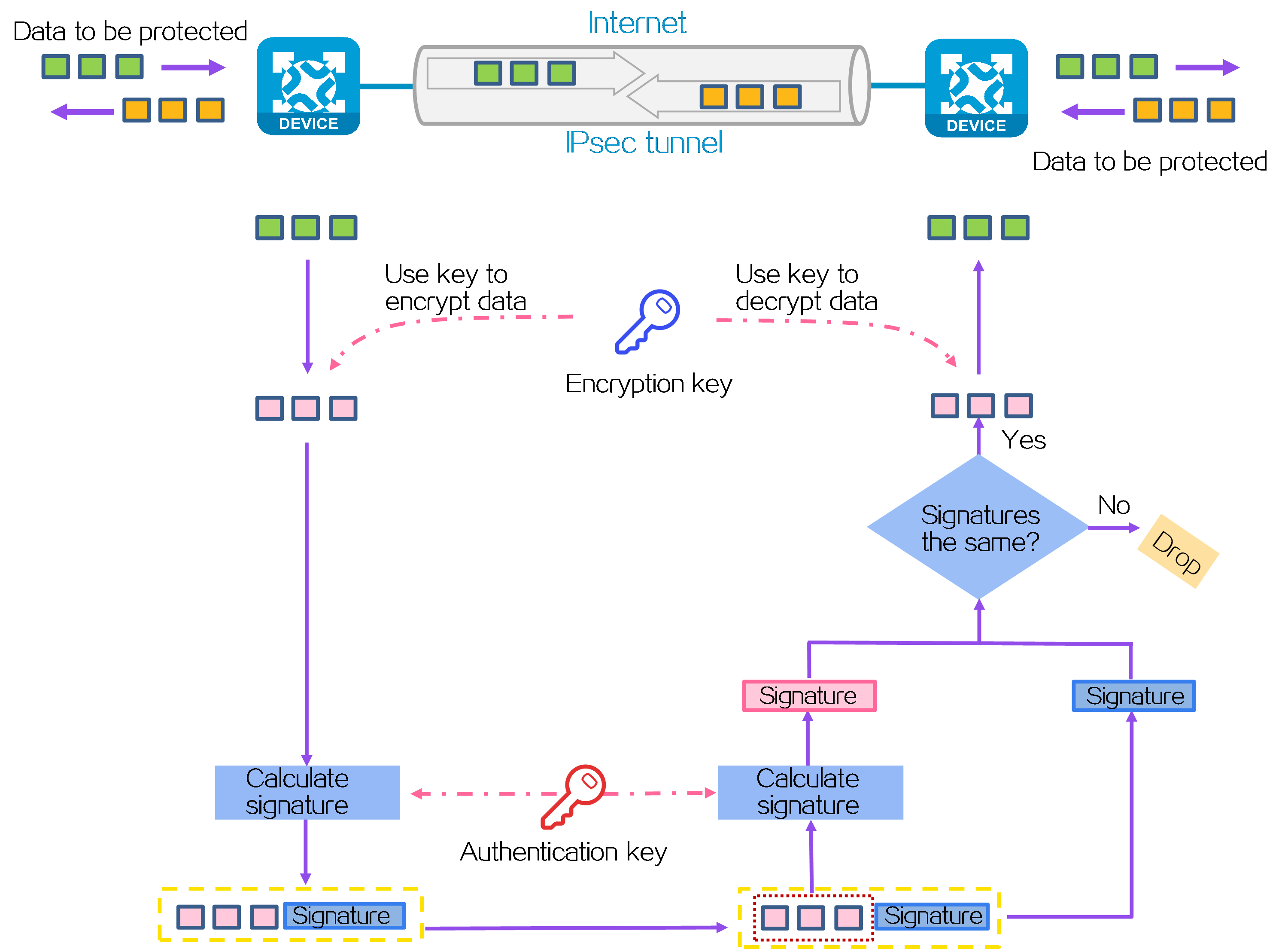
Mechanism
As shown in Figure 8, IPsec operates as follows:
1. Define data flows to be protected by IPsec based on ACLs or routing settings. For more information, see "Data flows to be protected."
2. The IPsec peers determine the data protection and authentication policy (including the security protocols, authentication and encryption algorithms, keys, and the key lifetime) and establish the IPsec tunnel accordingly, using one of the following methods:
¡ Manual configuration—Configures all settings for the IPsec tunnel through commands. The IPsec tunnel is established immediately after the configuration is complete.
¡ IKEv1 negotiation—Uses IKEv1 to negotiate an IPsec policy automatically. After IKEv1 is configured, data flows from the initiator can trigger the setup of the IPsec tunnel.
¡ IKEv2 negotiation—Uses IKEv2 to negotiate an IPsec policy automatically. After IKEv2 is configured, data flows from the initiator can trigger the setup of the IPsec tunnel.
¡ Quantum encryption—Obtains quantum keys from the quantum key server to negotiate an IPsec policy automatically. After the required configuration is complete, data flows from the initiator can trigger the setup of the IPsec tunnel.
¡ Group Domain of Interpretation (GDOI) negotiation—Group domain VPN uses a group-based IPsec model. Members in a group use a common IPsec policy, which includes security protocols, algorithms, and keys. This reduces management complexity and increases scalability.
¡ SDWAN negotiation—An SDWAN IPsec profile is used to generate IPsec SAs on SDWAN devices. It is applied to an SDWAN tunnel interface to protect all the traffic routed to the interface. You do not need to specify the remote end address or an ACL.
3. The IPsec initiator uses an encryption key and algorithm to encrypt a packet to be protected. A signature is generated through the authentication algorithm and key, and is encapsulated in the packet for transmission.
4. The responder uses the same authentication algorithm and authentication key to generate a new signature for the received encrypted packet, and then compares it with the signature in the packet. If the signatures are different, the packet is illegitimate and will be discarded. If the signatures are the same, the packet is legitimate. The legitimate packet is decrypted by the decryption algorithm and key. Then, the responder obtains the original packet.
Data flows to be protected
IPsec protects specific traffic defined in the following methods:
· ACL-based IPsec—An ACL is used to define the data flows to be protected by IPsec. Packets that match a permit rule of the ACL will be protected by IPsec, and packets that do not match any permit rule will not be protected by IPsec. You can use ACLs to flexibly specify methods for using IPsec to protect packets.
· Tunnel interface-based IPsec—After you create an IPsec tunnel on a tunnel interface, IPsec will protect all packets routed to the tunnel interface unless users specify that a packet does not need protection. Tunnel interface-based IPsec simplifies IPsec configuration, and supports dynamic routing protocols and multicast traffic protection.
ACL-based IPsec
To implement ACL-based IPsec, configure an ACL to define the data flows to be protected, specify the ACL in an IPsec policy, and then apply the IPsec policy to an interface. You can apply an IPsec policy to physical interfaces such as Ethernet interfaces, or virtual interfaces such as tunnel interfaces and virtual template interfaces.
ACL-based IPsec operates as follows:
· When packets sent by the interface match a permit rule of the ACL, the packets are protected by the outbound IPsec SA and encapsulated with IPsec.
· When the interface receives an IPsec packet destined for the local device, it searches for the inbound IPsec SA according to the SPI in the IPsec packet header for de-encapsulation. By default:
¡ If the de-encapsulated packet matches a permit rule of the ACL, the device processes the packet.
¡ If the de-encapsulated packet does not match any permit rule of the ACL, the device drops the packet.
If ACL checking for de-encapsulated packets is disabled, the device does not the de-encapsulated packet that does not match any permit rule of the ACL.
The device supports the following data flow protection modes:
· Standard mode—One IPsec tunnel protects one data flow. The data flow permitted by an ACL rule is protected by one IPsec tunnel that is established solely for it.
· Aggregation mode—One IPsec tunnel protects all data flows permitted by all the rules of an ACL. This mode is only used to communicate with old-version devices.
· Per-host mode—One IPsec tunnel protects one host-to-host data flow. One host-to-host data flow is identified by one ACL rule and protected by one IPsec tunnel established solely for it. This mode consumes more system resources when multiple data flows exist between two subnets to be protected.
Tunnel interface-based IPsec
Tunnel interface-based IPsec is also known as virtual tunnel interface (VTI)-based IPsec.
To implement tunnel interface-based IPsec, configure an IPsec profile and apply the IPsec profile to a tunnel interface. IPsec will protect all traffic routed to the tunnel interface, except the traffic that you specify not to protect. Tunnel interface-based IPsec supports only the tunnel encapsulation mode.
Compared with ACL-based IPsec, tunnel interface-based IPsec has the following advantages:
· Supports multicast traffic protection.
· Supports dynamic routing protocol advertisement between the IPsec tunnel peers.
· Simplifies configuration. Tunnel interface-based IPsec does not require using ACL rules to define the traffic to be protected. The routing table directs the traffic to the tunnel interface for protection.
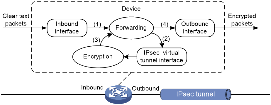
For tunnel interface-based IPsec, packet encapsulation and decapsulation are performed on the tunnel interfaces.
As shown in Figure 9, a tunnel interface encapsulates an IP packet as follows:
1. Upon receiving a clear text packet, the input interface sends the packet to the forwarding module for routing.
2. If the packet requires IPsec protection, the forwarding module sends the packet to the tunnel interface.
3. The tunnel interface encapsulates the packet into a new IP packet. The source and destination IP addresses in the new IP header are the source and destination IP addresses of the tunnel interface. Then, the tunnel interface sends the packet back to the forwarding module.
4. The forwarding module looks up the routing table again and sends the packet out of the physical interface of the tunnel interface.
Figure 9 Tunnel interface encapsulation
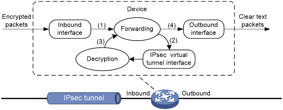
As shown in Figure 10, a tunnel interface de-encapsulates an IP packet as follows:
1. Upon receiving an encrypted packet, the inbound interface sends the packet to the forwarding module for routing.
2. Because the packet is destined for the tunnel interface's source address and the payload protocol is AH or ESP, the forwarding module sends the packet to the tunnel interface.
3. The tunnel interface de-encapsulates the packet (removes the outer IP header) and sends the de-encapsulated packet back to the forwarding module.
4. The forwarding module looks up the routing table again and sends the packet out of the output interface.
Figure 10 Tunnel interface de-encapsulation
H3C implementation of IPsec
Hardware crypto engine with high security and efficiency
Both software and hardware crypto engines can implement encryption/decryption and authentication algorithms for IPsec. The IPsec feature is resource intensive for its complex encryption/decryption and authentication algorithms. To improve processing performance, you can use a hardware crypto engine to offload IPsec tasks.
If the device is enabled with hardware crypto engines, the hardware crypto engine processes all IPsec protected packets and hands the processed packets back to the device for forwarding.
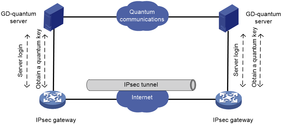
Quantum encryption with high security
After enabling GD-quantum encryption for IKE, the device can use the symmetric key provided by the GD-quantum server to encrypt the IPsec protected data, which further enhance the security of IPsec.
The device obtains keys from the GD-quantum server in the following steps:
1. Connecting the GD-quantum server—After GD-quantum encryption settings are configured, the device establishes a connection with the specified GD-quantum server.
2. Logging in to the GD-quantum server—After the connection is established, the device sends a login request to the GD-quantum server, carrying the GD-quantum access ID and the GD-quantum authentication key. Only devices with verified GD-quantum access IDs and GD-quantum authentication keys can successfully log in to the GD-quantum server.
3. Obtaining the GD-quantum keys—After successful login and the IKE phase 1 negotiation, the device obtains the encrypted GD-quantum keys from the GD-quantum server, decrypt them with the GD-quantum decryption keys configured on the device, and finally obtain the GD-quantum keys for IPsec.
Figure 11 GD-quantum encryption mechanism
Support for GM algorithms
IPsec supports mainstream GM algorithms, including SM1, SM2, SM3, and SM4.
IPsec smart link selection
To improve network stability and availability, a branch's IPsec gateway typically deploys multiple links to connect to the corporate headquarters. The qualities of these links (in terms of packet loss ratio and delay) are not static but keep changing with time. It is important that the branch gateway can dynamically select a link with desired transmission quality to establish the IPsec tunnel to the headquarters. IPsec smart link selection can meet this requirement.
IPsec smart link selection enables the branch gateway to monitor the real-time packet loss ratio and delay of the active link over which the IPsec tunnel is established. If the packet loss ratio or delay of the link exceeds the specified threshold, IPsec smart link selection reselects a link for the IPsec tunnel. You can also manually activate a link to establish the IPsec tunnel over that link.
The IPsec smart link selection process is as follows:
1. When the branch gateway identifies traffic that needs IPsec protection for the first time, it establishes an IPsec tunnel to the headquarters over the link with the highest priority.
After a link is selected for IPsec tunnel establishment, the device applies the IPsec policy that uses the IPsec smart link policy to the local interface of the link.
2. The device periodically sends probe packets to test the packet loss ratio and delay over the active link.
3. If the packet loss ratio or delay over the link exceeds the configured threshold, the device starts a cyclic link switchover process, during which a qualified link is selected to transfer traffic.
Cyclic link switchover probes the available links one by one in descending order of the link priority, and uses the first qualified link to transfer traffic. If no links are qualified when the maximum number of link switchover cycles is reached, the device selects a link for traffic as follows:
¡ Selects the link with the lowest packet loss ratio.
¡ Selects the link with the lowest delay if the links have the same packet loss ratio.
¡ Selects the link with the lowest priority if the links have the same packet loss ratio and delay.
After 10 minutes, the device starts link quality probing and cyclic link switchovers again.
IPsec RRI
IPsec Reverse Route Injection (RRI) enables an IPsec tunnel gateway to automatically add and delete static routes destined for the protected private networks. It automatically adds the static routes when the IPsec SAs are established and deletes the static routes when the IPsec SAs are deleted. This greatly reduces the static route configuration work load on the gateway and increases the scalability of the IPsec VPN.
IPsec RRI is applicable to gateways that must provide many IPsec tunnels (for example, a headquarters gateway).
As shown in Figure 12, the traffic between the enterprise center and the branches are protected by IPsec. The gateway at the enterprise center is configured with static routes to route traffic to the IPsec-protected interfaces. It is difficult to add or modify static routes on the gateway at the enterprise center if the IPsec VPN has a large number of branches or if the network structure changes.
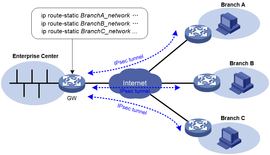
After you can enable IPsec RRI on the gateway, the gateway automatically adds a static route to the routing table each time an IPsec tunnel is established. The destination IP address is the protected private network. The next hop IP address can be the remote IP address of the IPsec tunnel (default) or a user-defined next hop IP address. Traffic destined for the peer end is routed to the IPsec tunnel interface and thereby protected by IPsec.
You can advertise the static routes created by IPsec RRI in the internal network, and the internal network device can use them to forward traffic in the IPsec VPN.
You can set preferences for the static routes created by IPsec RRI to implement flexible route management. For example, you can set the same preference for multiple routes to the same destination to implement load sharing, or you can set different preferences to implement route backup.
You can also set tags for the static routes created by IPsec RRI to implement flexible route control through routing policies.
IPv6 routing protocol-based IPsec
You can implement IPv6 routing protocol-based IPsec by binding an IPsec profile to an IPv6 routing protocol. All packets of the protocol are encapsulated with IPsec. Supported IPv6 routing protocols include OSPFv3, IPv6 BGP, and RIPng.
All packets of the applications that are not bound to IPsec and the IPsec packets that failed to be de-encapsulated are dropped.
In one-to-many communication scenarios, you must configure the IPsec SAs for an IPv6 routing protocol in manual mode because of the following reasons:
· The automatic key exchange mechanism protects communications between two points. In one-to-many communication scenarios, automatic key exchange cannot be implemented.
· One-to-many communication scenarios require that all the devices use the same SA parameters (SPI and key) to receive and send packets. IKE negotiated SAs cannot meet this requirement.
IPsec for SDWAN packets
About SDWAN
Software-defined WAN (SDWAN) is a VPN technology that applies SDN to the WAN scenarios. The control plane advertises Transport Tunnel Endpoint (TTE) and EVPN route information through the standard MP-BGP to implement MAC address and IP address learning and advertisement between sites. The data plane uses UDP to encapsulate and forward data packets and provides fast, secure and reliable data transport between physically dispersed enterprise networks and data centers.
SDWAN network model
Figure 13 SDWAN network diagram
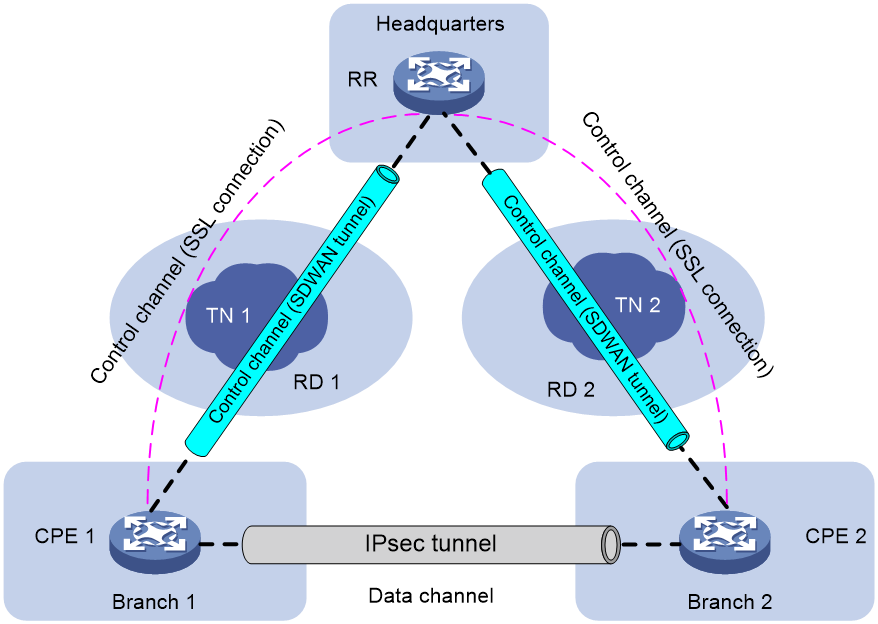
As shown in Figure 13, an SDWAN network comprises control channels and data channels. Each CPE generates an IPsec SA and advertises the IPsec SA to other CPEs through the RR's control channels. When there is data to be transmitted between CPEs over the data channel, the CPEs use the IPsec SAs to protect the transmitted data.
For example, when CPE 1 sends packets to CPE 2, CPE 1 first encrypts the packets by using the IPsec SA of CPE 2 and then sends the encrypted packets to CPE 2. After CPE 2 receives the packets, it uses its own IPsec SA to decrypt the packets and discards the unencrypted packets. When CPE 2 sends packets to CPE 1, CPE 2 first encrypts the packets by using the IPsec SA of CPE 1 and then sends the encrypted packets to CPE 1. After CPE 1 receives the packets, it uses its own IPsec SA to decrypt the packets and discards the unencrypted packets.
IPsec SAs are unidirectional. Packet encryption and decryption use different IPsec SAs. Typically, the device uses the locally generated IPsec SAs for encryption and the IPsec SAs received from remote devices for decryption.
Hereinafter, the locally generated IPsec SAs are referred to as local IPsec SAs and the IPsec SAs received from remote devices are referred to as remote IPsec SAs.
Netmask filtering and flow overlap check
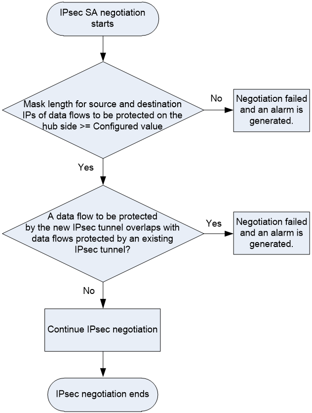
On a hub-spoke network, if the IPsec data flow range configured on a spoke is much larger than other spokes, traffic of other spokes might be directed to that spoke incorrectly. To avoid incorrect packet forwarding, you can enable IPsec netmask filtering on the hub device.
When negotiating an IPsec SA for a data flow, the device checks the mask lengths of the data flow. The IPsec SA negotiation proceeds only if the mask lengths of the source and destination IP addresses of the data flow are greater than or equal to those configured by IPsec netmask filtering. If the data flow fails to pass the netmask filtering, the IPsec SA negotiation fails and the device generates a corresponding SA negotiation failure notification. The notification indicates that the mask length of the data flow to be protected is too small. On receiving such notifications, you must reconfigure the ACL settings for IPsec on the spoke devices. For example, branch A and branch B performs IPsec SA negotiation with the headquarters. The source address in the ACL rule configured on branch A is 192.168.1.0/24, and the source address in the ACL rule configured on branch B is 192.168.0.0/8. The traffic that matches branch A also matches branch B. Since the device matches ACL rules in sequence, the traffic that is destined for branch A might be sent to branch B.
The data flows to be protected by the IPsec SAs might overlap with each other. To avoid IPsec flow overlapping, you can enable IPsec flow overlap check on the hub device. When negotiating an IPsec SA for a data flow, the device checks whether the data flow overlaps with an existing protected data flow. If yes, the new IPsec SA negotiation fails and the device generates an IPsec flow overlap notification. On receiving such notifications, you must reconfigure the ACL settings for IPsec on the spoke devices.
This flow overlap check feature checks the destination IP address of a data flow to be protected with the destination IP addresses of the existing protected data flows. If an overlap exists, the feature determines that the data flow overlaps.
The workflow of IPsec netmask filtering and flow overlap check is as shown in Figure 14.
Figure 14 Workflow of IPsec netmask filtering and flow overlap check
IPsec no NAT
By default, on an interface where both IPsec and NAT are configured, the device performs NAT processing before IPsec processing for outgoing packets. Packets after NAT cannot match with ACL rules, which cause the packets to fail to be processed by IPsec. For packets to be protected by IPsec correctly on the interface, you must deploy complicated configuration to identify traffic for NAT and that for IPsec.
After the IPsec no NAT feature is enabled, the device does not perform NAT for the traffic to be processed by IPsec. So, you do not need to distinguish traffic for NAT and IPsec, reducing the configuration complexity.
Peer address backup and switchback
Peer address backup
For high availability, the IPsec gateway of the headquarters is configured with multiple links for redundancy. With peer address backup, a branch's IPsec gateway will initiate negotiations with other backup addresses of the headquarters to establish an IPsec tunnel when a link of the headquarters fails.
IPsec supports specifying multiple peer IP address as a peer IP address list. To establish an IPsec tunnel, the local end initiates an IPsec negotiation with IP addresses in the list according to the configuration order. If the negotiation succeeds, an IPsec tunnel is established. If the negotiation fails, the local end will initiate a negotiation with the next IP address in the list until the last IP address.
You can also specify a preferred IP address in the IP address list. That is, this IP address has the highest priority. Each time a negotiation is triggered, the negotiation uses this IP address first. If the negotiation with the preferred IP address fails, the local end will initiate a negotiation with the IP address following the preferred IP address in the list until the last address.
Peer address switchback
After a peer IPsec address is associated with a track entry, the device can detect the status of the peer address. If the preferred address or a backup address is unavailable, the device will immediately establish an IPsec with another address. The peer address switchback feature allows the device to re-establish an IPsec tunnel with the preferred address when the preferred address becomes available. If the peer address switchback feature is disabled, the device will not re-establish an IPsec tunnel with the preferred address when the preferred address becomes available.
Flexible encapsulation protocol switching
IPsec supports two encapsulation protocols at the transport layer, UDP and TCP.
By default, IPsec uses UDP for encapsulation. When UDP packets are blocked or restricted in the network, IPsec packets can be encapsulated into TCP packets for transmission.
IMC-based unified IPsec O&M
The IMC-based VPN solution, IPsec VPN Manager (IVM), can manage IPsec VPNs in the following aspects, which IPsec VPNs cannot completes:
· Completing quick deployment since the IPsec VPN technology is complex with many commands.
· Monitoring the operating status of IPsec VPN networks.
· Monitoring the performance of tenant VPNs.
· Quickly locating IPsec VPN device faults.
Application scenarios
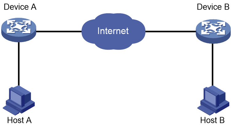
LAN interconnection
As shown in Figure 15, establish an IPsec tunnel between Device A and Device B to protect data transmitted between two LANs.
Remote access from mobile users
As shown in Figure 16, establish an IPsec tunnel between the host of a remote user and the device to protect data flows between the host and the internal server.

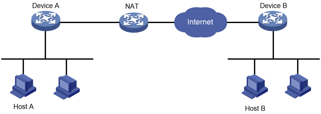
NAT traversal
As shown in Figure 17, Establish an IPsec tunnel between Device A and Device B to secure communications between two LANs. Device A is behind the NAT device and IPsec supports NAT traversal.
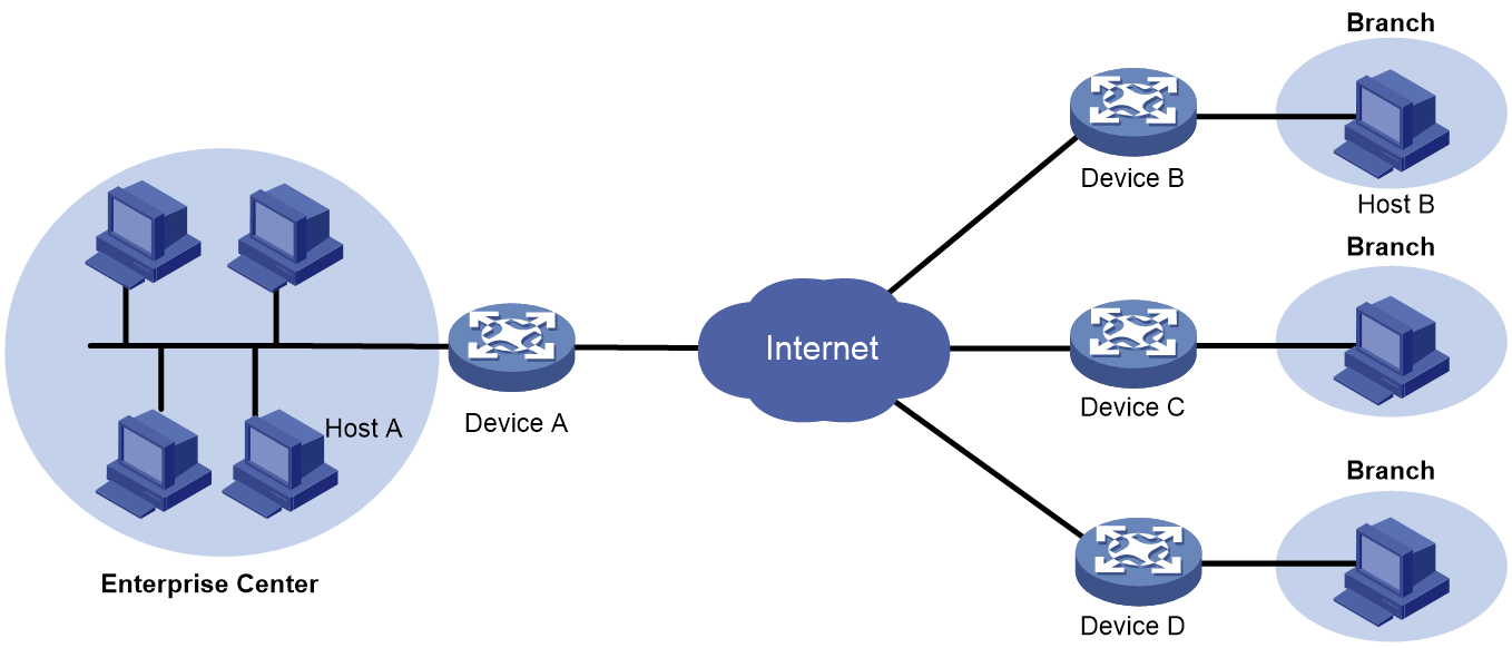
IPsec RRI
As shown in Figure 18, branches access the enterprise headquarters through an IPsec VPN. Configure IPsec RRI on Device A to automatically create static routes to the branches based on the established IPsec SAs.
Figure 18 Network diagram
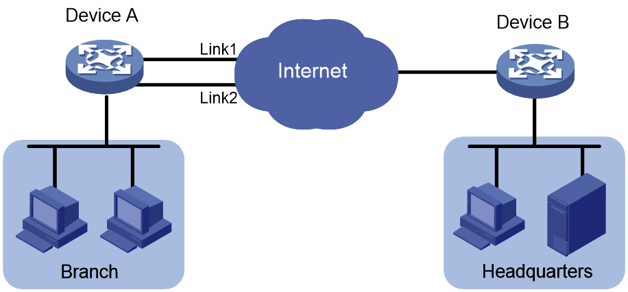
IPsec smart link selection
As shown in Figure 19, branches access the enterprise headquarters through an IPsec VPN. Configure IPsec smart link selection on Device A so the branch can establish an IPsec tunnel to the headquarters over link 1 or link 2, whichever has a better link quality.
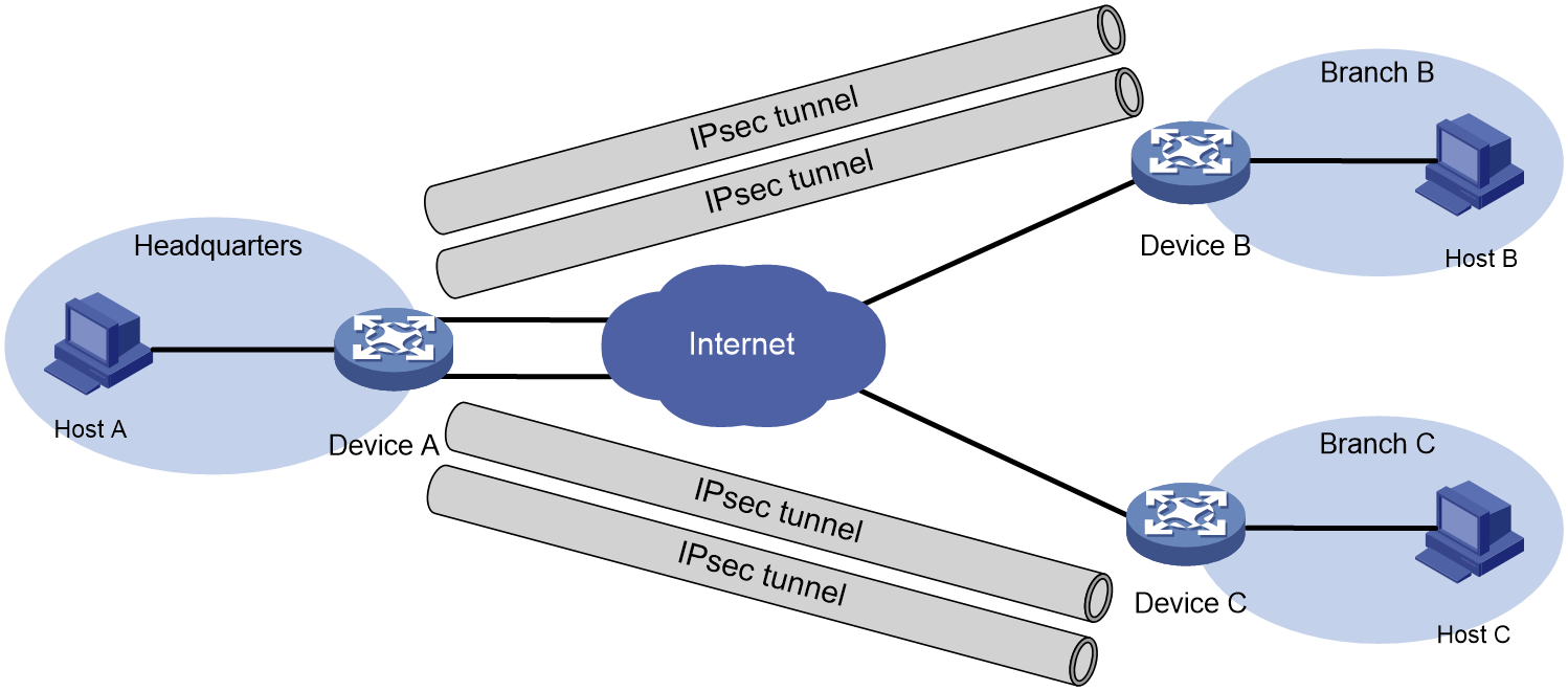
Headquarters with dual links
As shown in Figure 20, the headquarters gateway device Device A has two links connected to the Internet. Branch gateway devices Device B and Device C each has one link connected to the Internet. The headquarters and the branches select high-quality, low-latency links based on the NQA test results to dynamically establish IPsec tunnels.
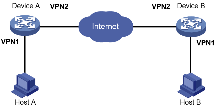
IPsec in multiple VPN instances
As shown in Figure 21, the internal port and external port on the gateway devices for the enterprise headquarters and the branch belong to different VPN instances. Establish an IPsec tunnel between the headquarters and the branch to secure the communication.
References
· RFC2408: Internet Security Association and Key Management Protocol (ISAKMP)
· RFC2409: The Internet Key Exchange (IKE)
· RFC2412: The OAKLEY Key Determination Protocol
· Internet-Draft: draft-ietf-ipsec-isakmp-xauth-06.txt
· Internet-Draft: draft-dukes-ike-mode-cfg-02.txt
· RFC 2408: Internet Security Association and Key Management Protocol (ISAKMP)
· RFC 4306: Internet Key Exchange (IKEv2) Protocol
· RFC 4718: IKEv2 Clarifications and Implementation Guidelines
· RFC 2412: The OAKLEY Key Determination Protocol
· RFC 5996: Internet Key Exchange Protocol Version 2 (IKEv2)
