- Released At: 19-12-2020
- Page Views:
- Downloads:
- Table of Contents
- Related Documents
-
|
|
|
WLAN Dual-AC IRF |
|
Technology White Paper |
|
|
|
|
Copyright © 2020 New H3C Technologies Co., Ltd. All rights reserved.
No part of this manual may be reproduced or transmitted in any form or by any means without prior written consent of New H3C Technologies Co., Ltd.
Except for the trademarks of New H3C Technologies Co., Ltd., any trademarks that may be mentioned in this document are the property of their respective owners.
The information in this document is subject to change without notice.
Contents
Implementation of IRF in AC services
Improved CAPWAP request processing efficiency
Standalone dual-AC IRF fabric with direct IRF connection
Standalone dual-AC IRF fabric with indirect IRF connection
Dual-AC IRF fabric hosted in a standalone switch chassis
Dual-AC IRF fabric hosted in a dual-switch IRF fabric
Overview
H3C Intelligent Resilient Framework (IRF) technology virtualizes multiple physical devices into one virtual system called an IRF fabric for increased processing capability, unified management, and uninterrupted maintenance. This document describes the application of IRF in AC services.
About dual-AC IRF
To increase wireless service availability, you can virtualize two access controllers (ACs) into an IRF fabric. This IRF fabric appears as one node on the network and is manageable from one single point of management. When one AC fails, the other AC takes over to provide services to APs.
Benefits
Dual-AC IRF provides the following benefits:
· Simplified topology—An IRF fabric appears as one node on the network. Any topological changes in the IRF fabric are transparent to APs.
· Single point of management—The IRF fabric is accessible at a single IP address on the network. You can use this IP address to log in at any member AC to manage all the members of the IRF fabric.
· Node redundancy—In a dual-AC IRF fabric, one member acts as the master to control the entire IRF fabric and process services, and the other member backs up the master. When the master fails, the other member takes over the master role to process services. The original AC can join the IRF fabric as the standby AC after it recovers.
· Ease of deployment and configuration—A dual-AC IRF deployment does not require any extra settings or changes on the AP side. In addition, you configure services on a dual-AC IRF fabric in the same way you configure services on a standalone AC. The software will automatically synchronize the configuration between the master and standby ACs and restore the configuration and services on a master/standby switchover without any manual intervention.
· License sharing—The ACs in an IRF fabric share their license resources. You only need to consider the number of APs to be connected when you plan the AP license capacity.
Implementation of IRF in AC services
Concepts
Master AC: The AC that controls the entire IRF fabric and processes service traffic.
Standby AC: The AC that backs up the master AC. When the master fails, the standby AC takes over the master role to provide services. The standby AC is also called the subordinate AC.
CAPWAP: Control And Provisioning of Wireless Access Point protocol. It defines how an AP communicates with an AC and provides a generic encapsulation and transport mechanism between AP and AC.
Configuration synchronization
IRF uses an automatic running-configuration synchronization mechanism. When an AC joins an IRF fabric as the standby AC, the master AC automatically synchronizes its running configuration to the configuration database of the standby AC. During the runtime, the master AC synchronizes configuration changes to the configuration database of the standby AC in real time.
Improved CAPWAP request processing efficiency
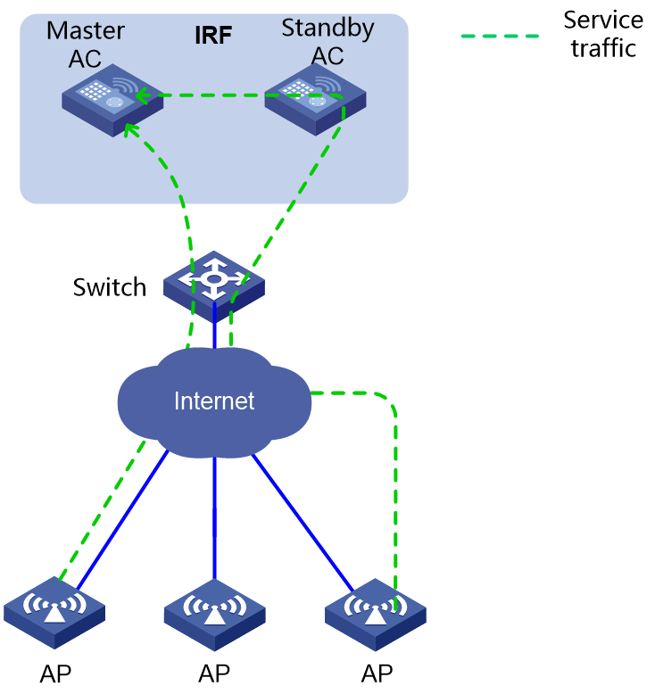
As shown in Figure 1, a dual-AC IRF fabric typically establishes a multi-AC link aggregation to its downstream or upstream device. Traffic enters the IRF fabric from links connected to the master and standby ACs in a link aggregation. The standby AC passes all incoming traffic to the master AC without any processing except the first CAPWAP packet from an AP, which triggers CAPWAP tunnel establishment.
When receiving the first CAPWAP packet from an AP, the standby AC checks the packet for its validity and verifies whether the maximum number of concurrent CAPWAP tunnels has been reached. If the packet is invalid or the maximum number of concurrent CAPWAP tunnels has been reached, the standby AC drops the packet. If the packet is valid and the maximum number of concurrent CAPWAP tunnels has not been reached, the standby AC passes the packet to the master AC.
This processing mechanism improves the efficiency of the master AC in processing CAPWAP tunnel establishment requests and eliminates the processing pressure on the master AC.
Figure 1 Service traffic model in a dual-AC IRF fabric
Failover mechanisms
When the master AC fails, the standby AC takes over the master role and restores the configuration and services in sequence to provide services to APs.
Configuration restoration
The standby AC uses the following procedure to restore the configuration after it takes over the master role:
1. Activates the configuration shell so the user can retrieve and issue settings.
2. Each service module (for example, station management and portal authentication) reads their data and settings in sequence from the configuration database to the running configuration in memory.
The service modules can then use the restored data and configuration to make processing decisions and respond to the retrieval or configuration requests from users.
Service restoration
The standby AC restores its services one by one after it takes over the master role. During this process, the Layer 2 links of the standby AC can continue to send and receive traffic after a transient loss of connection.
The new master AC uses the following procedure to restore its services:
1. Initializes the global service data.
In this phase, the AC restores the global service data required for each module to run. The following are some operations performed by the AC in this phase:
¡ Closes the service ports that are not needed when it operates as the master.
¡ Opens the service ports that are required for it to run as the master.
¡ Restores the service resource counters.
¡ Establishes connections between service processes.
¡ Starts service timers.
2. Restores the services.
After restoring the configuration and global service data, the AC can receive and process incoming service packets as the master.
3. Re-establishes the CAPWAP tunnels.
The APs automatically send CAPWAP requests to the AC after they have failed to receive service responses from the original master AC. On receipt of these requests, the new master AC quickly re-establishes CAPWAP tunnels with the requesting APs and provides services to them.
4. Full recovery of services.
After all service modules on the AC restore their services, the WLAN service functionality recovers completely.
License sharing
The ACs in the dual-AC IRF fabric share their licenses. The licenses running before a master/standby switchover continue to take effect after the switchover.
For more information about license sharing on an IRF fabric, see H3C WLAN AP License Sharing Technology White Paper and H3C WLAN IRF 2.0 Technology White Paper.
Application scenarios
Typical deployments
An AC comes in the form of a standalone device or a service module.
The following are typical deployments for AC devices:
· Standalone dual-AC IRF fabric with direct IRF connection
· Standalone dual-AC IRF fabric with indirect IRF connection
|
|
NOTE: As a best practice, use the direct IRF connection deployment. |
The following are typical deployments for AC modules:
· Dual-AC IRF fabric hosted in a standalone switch chassis
· Dual-AC IRF fabric hosted in a dual-switch IRF fabric
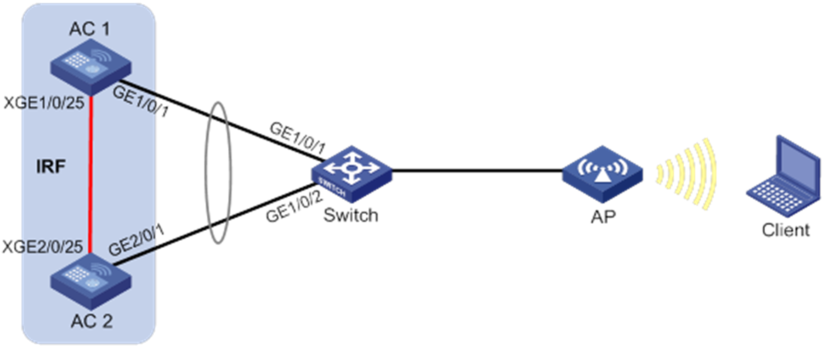
Standalone dual-AC IRF fabric with direct IRF connection
In this deployment, you set up a direct IRF connection between two AC devices and establish a dynamic dual-AC link aggregation with the remote switch, as shown in Figure 2.
Figure 2 Dual-AC IRF fabric with direct IRF connection
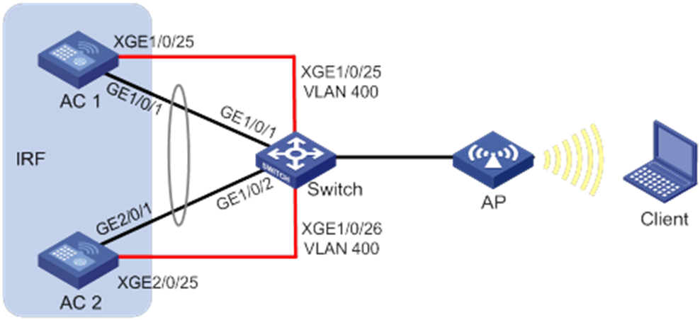
Standalone dual-AC IRF fabric with indirect IRF connection
In this deployment, you set up an IRF connection between two AC devices over a switch and establish a dynamic dual-AC link aggregation with the switch, as shown in Figure 3.
Figure 3 Standalone dual-AC IRF fabric with indirect IRF connection
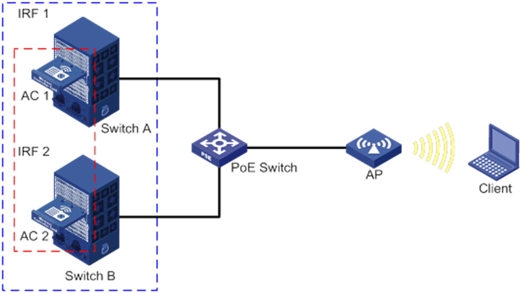
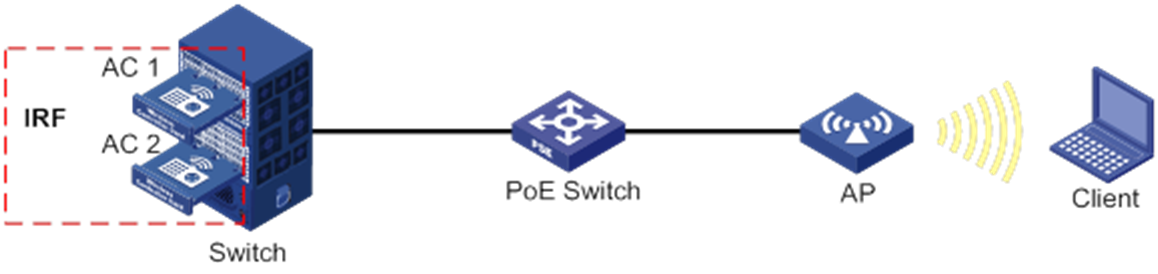
Dual-AC IRF fabric hosted in a standalone switch chassis
In this deployment, you install two AC modules in a switch chassis and establish an IRF connection between their internal ports, as shown in Figure 4.
In addition, use the remaining internal ports of the ACs to establish a dual-AC dynamic link aggregation with the switch chassis.
Figure 4 Dual-AC IRF fabric hosted in a standalone switch chassis
Dual-AC IRF fabric hosted in a dual-switch IRF fabric
In this deployment, you install one AC module in each member of a dual-switch IRF fabric, and establish an IRF connection between internal ports of the ACs, as shown in Figure 5.
In addition, use the remaining internal ports to establish a dual-AC dynamic link aggregation with the dual-switch IRF fabric.
Figure 5 Dual-AC IRF fabric hosted in a dual-switch IRF fabric