- Released At: 20-11-2020
- Page Views:
- Downloads:
- Table of Contents
- Related Documents
-
|
|
|
H3C Servers RAS |
|
Technology White Paper |
|
|
|
|
Copyright © 2020 New H3C Technologies Co., Ltd. All rights reserved.
No part of this manual may be reproduced or transmitted in any form or by any means without prior written consent of New H3C Technologies Co., Ltd.
Except for the trademarks of New H3C Technologies Co., Ltd., any trademarks that may be mentioned in this document are the property of their respective owners.
The information in this document is subject to change without notice.
Overview
The server is one of the key components of any modern data center infrastructure. It includes various components such as processors, storage devices, PCIe devices, power supplies, and fans. To ensure service continuity, correct server operation and data integrity are critical to a modern data center. In other words, we must avoid data corruption no matter data is stored in any server component (memory, cache, or processor registers) or transmitted through any platform links (Intel®UPI, PCI Express, or DMI).
When a server component fails, the set of reliability, availability and serviceability (RAS) features can meet the above requirements by maximizing service availability and maintaining data integrity.
Table 1 RAS definition based on H3C G3 servers
|
Item |
Definition |
|
Reliability |
Probability that the system produces the correct output within a given time T, as measured by the mean time between failures (MTBF) metric. It can be enhanced by avoiding, detecting, and repairing hardware failures. A reliable system does not provide incorrect data and calculation results, but can detect and correct data corruption. |
|
Availability |
Probability of correct system running at a given time, and the percentage of the actual running time of the server to the actual running time. |
|
Serviceability |
How easy and fast the system can be repaired or maintained. If the time for the system to repair errors increases, the serviceability decreases. Serviceability can be improved by simplifying system issue diagnosis and providing clear and intelligent advance warnings of failures to avoid system failures. |
Figure 1 Error categories

Benefits
RAS can provide the following benefits:
· Increased system uptime—Increases system reliability for the system to stay longer, as measured by the Mean Time To Fail (MTTF), Annual Crash Rate (ACR), or Annual Service Rate (ASR) metric.
· Reduced the duration of unexpected downtime—Adopts Intel Xeon processors to support synchronized hardware and firmware logging, helping users to identify and isolate errors and take preventive or proactive maintenance measures. This enables quick system restoration, reduces the cost of repairs, and mitigates the consequences of the outage to the business.
Outages are inevitable even with the best plans and processes. When an unplanned outage happens, a maintainable system can come back online quickly, as measure by the Mean Repair Time (MTTR) matric.
· Enhanced data integrity—RAS provides several mechanisms to prevent data corruption or correct corrupted data, which ensures data corruption can get contained once detected.
Applicable products
This document is applicable to the following H3C UniServer G3 servers:
· H3C UniServer R2700 G3 server
· H3C UniServer R2900 G3 server
· H3C UniServer R4300 G3 server
· H3C UniServer R4700 G3 server
· H3C UniServer R4900 G3 server
· H3C UniServer R6700 G3 server
· H3C UniServer R6900 G3 server
· H3C UniServer R8900 G3 server
Using this document
The information in this document is subject to change over time.
The information in this document might differ from your product if it contains custom configuration options or features.
RAS system architecture
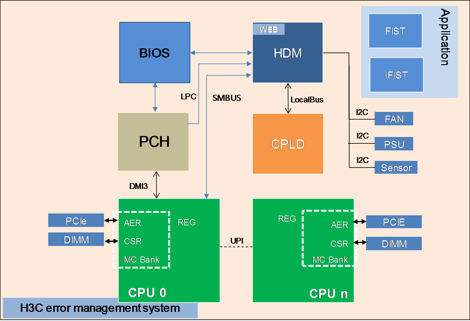
Based on MCA supported by Intel Xeon processors, H3C provides a complete error management system together with hardware, the BIOS, HDM, and OS error processing mechanisms. The system can provide functions such as error diagnosis, error location, error correction, information collection, and error reporting. Since the core of the system runs on the BIOS and HDM, it does not rely on the OS and can perform all-time detection of the system and take corresponding measures once an error occurs.
As shown in Figure 2, the error management system contains the hardware layer, CPLD, processor platform, HDM (out-of-band management), the BIOS, and OS.
· HDM—Core of the error location system. It is responsible for error information collection and analysis and can display error information as event logs or alarms from the Web interface.
· Processor platform—Supported by Intel Xeon processors, which compared with the previous generation provides enhanced RAS capabilities and more powerful management of errors occurred on processors, memory modules, and PCIe devices.
· CPLD—Connects downlink hardware modules, including power supplies, fans, and other underlying hardware (except processors, memory modules, drives, and standard PCIe modules), captures hardware exceptions, connects to HDM at the uplink, and transmits error information.
· BIOS—Collects and locates errors occurred on processors, memory modules, PCIe devices, and storage devices, provides error location results to HDM, and provides OS-level error management interfaces, such as WHEA, to the OS.
· FIST—Server management software developed by H3C. It can decode SDS log messages to record hardware and software events occurred during each service cycle, including main processor, BIOS, OS, and BMC events. This helps customer service or engineers to fast locate server issues and improve serviceability. This component is optional.
· iFIST—Single-server management tool embedded in each server. You can use iFIST to configure RAID settings, install the OS, install drivers, and diagnose server health conditions.
· Web interface—Web interface provided by management tools, such as HDM, for users to maintain the server locally or remotely. Users can use the Web interface together with LEDs of specific server components to manage the server.
· Involved protocols—Protocols used by the error management system includes LPC, PECI, PCIe, UART, I2C, SMBUS, and LocalBus.
Figure 2 H3C error management system architecture
RAS operating mechanism
RAS is realized mainly through the MCA and AER mechanisms.
· Machine Check Architecture (MCA)
The MCA mechanism can report and repair errors occurred on the system bus, ECC, parity check, cache, and TLB as much as possible, identify failure sources, and record failure information in the MC Bank.
Both correctable and uncorrectable errors can be reported. For correctable errors, the system attempts to repair the errors. For uncorrectable errors, a warm restart is usually performed. MCA can take effect on all modules in a processor, including core, uncore, and IIO (through IOMCA).
MCA records only the first uncorrectable error and the last correctable error.
· IIO Advanced Error Reporting (AER)
IIO AER is an optional extended function of PCI Express. Compared with standard PCI Express error reporting, IIO AER provides more powerful error reporting functions, including PCI Express AER, traffic switch, IRP, IIO core, Intel VT-d, CBDMA, and other Intel-specific expansions.
The IIO AER mechanism is responsible for detecting, recording, and sending error signals for submodules of various IIO modules, such as PCIe interfaces, DMI, IIO core logic, and Intel VT-d.
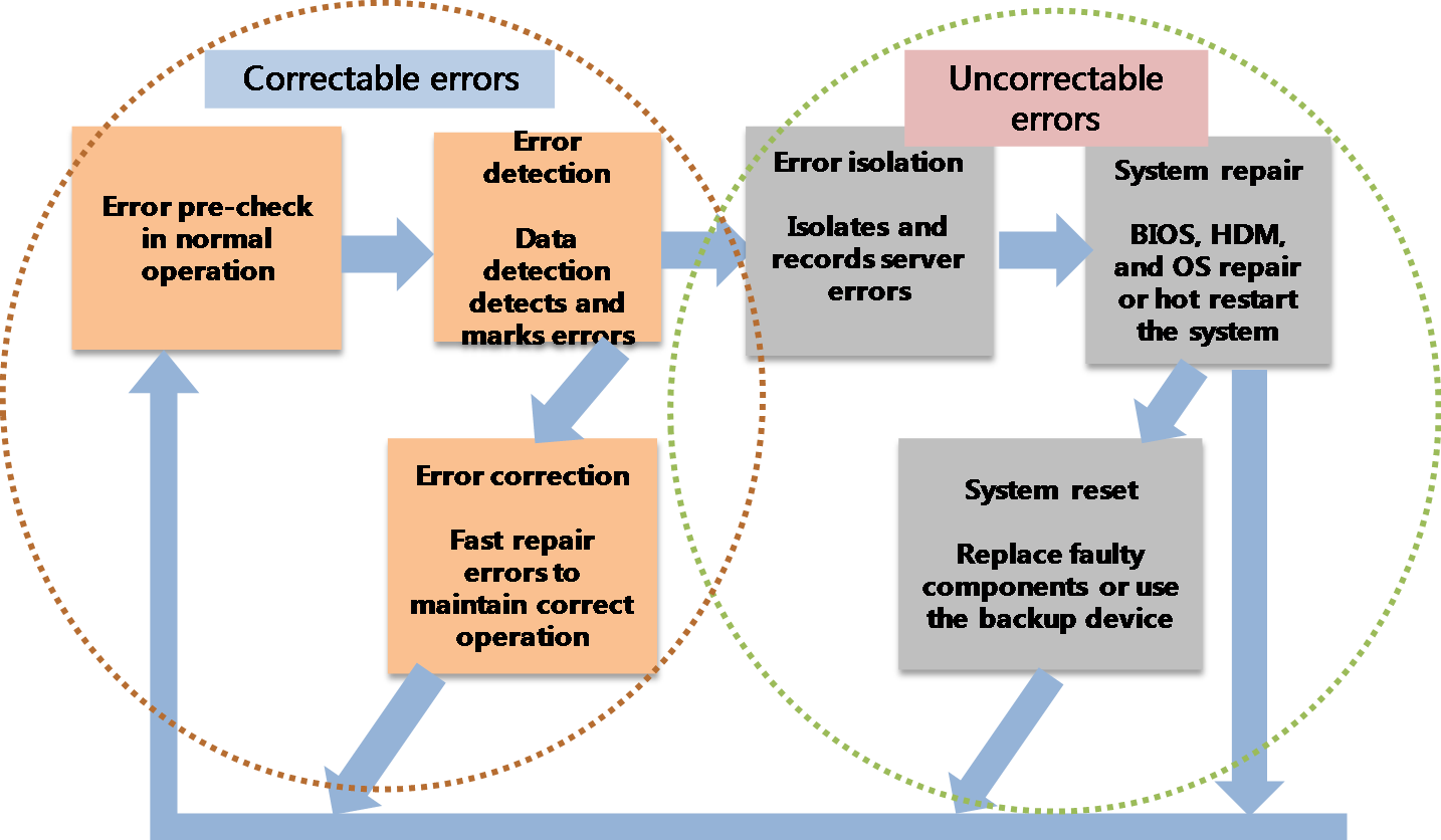
The basic error processing schemes of RAS are as follows:
· For correctable errors, RAS marks the error location and fast repair the corresponding module. Users will not aware the occurrence of such errors.
· For uncorrectable errors, RAS isolates the errors by isolating bad memory blocks or degrading the bus to maintain system operation. If severe errors occur and result in system outage, you must use HDM to restore or restart the system.
· For permanent hardware failures, you must replace the faulty component or use the backup device. You can replace hot swappable components without powering off the server.
Figure 3 RAS schemes
Error detection
As shown in Table 2, H3C G3 servers use different error detection methods for different modules to maintain high processor availability. Both error detection and correction events will be reported.
For more information about error detection methods, see "Error detection and correction (including the socket level)."
Table 2 Error detection methods for different modules
|
Module |
Definition/Submodule |
Detection method |
|
EE |
Execution/Engine |
Residue check |
|
IFU |
Instruction fetch unit (L1 I-Cache) |
Parity |
|
DCU |
Data cache unit (L1 D-cache) |
Parity |
|
I/DTLB |
Instruction/Data translation look aside buffer |
Parity |
|
MLC |
Mid level cache |
ECC |
|
CHA |
L3 cache: Data tag, MESIF state |
ECC |
|
Home agent |
Parity |
|
|
PCU |
Power controller unit |
Parity, stack overflow, time schemes |
|
IVR |
Integrated voltage regulators |
Overvoltage and overcurrent |
|
UPI |
Ultra path interconnect |
CRC |
|
Rx and Tx queues |
Parity |
|
|
IMC |
Read data buffer parity |
Parity |
|
Memory read write data byte enable |
ECC |
|
|
IIO/PCIe |
Integrated I/O: Phy and link layer |
CRC |
|
Rx/Tx queues |
Parity |
|
|
IIO, IRP, Inter VT-d, MISC, DMA errors |
||
|
Internal ring |
Internal ring - data and command (DPPP, APPP) |
Parity |
Error reporting
The system reports detected errors and generates error log messages. Error reporting requires the collaboration of the MCA, AER, memory correctable error reporting, and UPI correctable error reporting mechanisms.
Error reporting modes
The following error reporting modes are available:
· Legacy IA-32 MCA mode—Supported by several generations of Intel processors and most operating systems.
· Corrupt Data Containment (CDC) mode—An enhancement to the MCA mechanism. When the CDC mode detects an uncorrectable error, the detection agent forwards the error data with the poison flag set to the request agent.
· Enhanced MCA Gen1 (EMCA Gen1) mode—First-generation enhancement to the Legacy IA-32 MCA mode. It was developed to implement the firmware first model (FFM) of error reporting.
· Enhanced MCA Gen2 (EMCA Gen2) mode—Second-generation enhancement to the Legacy IA-32 MCA mode. It was developed to create a mode that can be enabled in the OS and further expanded the error reporting coverage of FFM.
· IOMCA mode—Allows IIO correctable and uncorrectable fatal errors to be signaled through MCE.
· Viral mode—Adopts hardware measures to improve error tolerance. The CDC mode can tolerate data errors, but the viral mode can tolerate address, control, and other fatal errors. This prevents errors from being submitted to drives or networks.
Some of the above modes are complementary to each other and can be enabled at the same time. Table 3 describes mode compatibility.
Table 3 Error reporting mode compatibility
|
Mode |
Legacy IA-32 MCA mode |
CDC mode |
EMCA Gen1 mode |
EMCA Gen2 mode |
IO MCA mode |
Viral mode |
|
Legacy IA-32 MCA mode |
Yes |
No |
No |
No |
Yes |
Yes |
|
CDC mode |
No |
Yes |
Yes |
Yes |
Yes |
Yes |
|
EMCA Gen1 mode |
No |
Yes |
Yes |
No |
Yes |
Yes |
|
EMCA Gen2 mode |
No |
Yes |
No |
Yes |
Yes |
Yes |
|
IO MCA mode |
Yes |
Yes |
Yes |
Yes |
Yes |
Yes |
|
Viral mode |
Yes |
Yes |
Yes |
Yes |
Yes |
Yes |
As shown in Table 4, the interrupt type used for error reporting depends on the error type.
Table 4 Error reporting interrupt
|
Error type |
Interrupt type |
Range |
Remarks |
|
|
Correctable errors |
Corrected Machine Check Interrupt (CMCI) |
Core/uncore |
Available only in IA23-legacy MCA mode |
|
|
Corrected SMI (CSMI) |
Core/uncore |
Available only in eMCA2 mode |
||
|
System Management Interrupt (SMI) |
Memory errors |
In-band communication between all sockets through UPI bus |
||
|
Message Signaled Interrupt (MSI) |
PCIe errors |
N/A |
||
|
ERROR_N[0] pin |
IIO AER and memory errors |
Can be used for BMC-based RAS |
||
|
Uncorrectable errors |
UCNA |
CMCI |
Core/uncore errors at the source |
Available only in IA23-legacy MCA mode |
|
MSMI |
Core/uncore errors at the source |
Available only in eMCA2 mode |
||
|
MSI and ERROR_N[1] pin |
Severity 1 IIO AER nonfatal errors |
N/A |
||
|
SRAO and SRAR |
MCERR |
Core/uncore errors |
Available only in IA23-legacy MCA mode |
|
|
MSMI |
Core/uncore errors at the source |
Available only in eMCA2 mode |
||
|
Catastrophic errors |
IERR |
Core/uncore errors |
Available only in IA23-legacy MCA mode |
|
|
MSMI |
Core/uncore errors at the source |
Available only in eMCA2 mode |
||
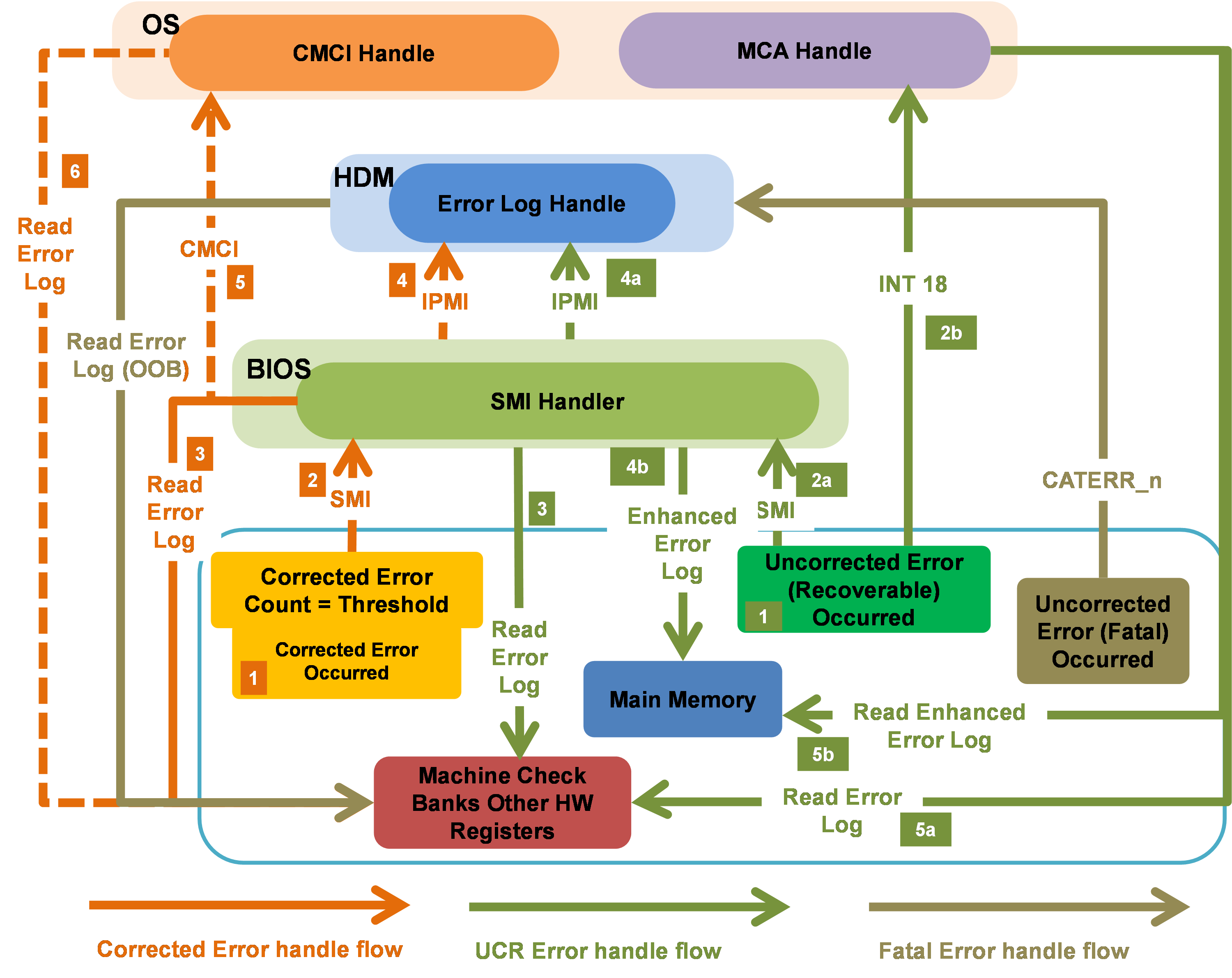
As shown in Figure 4, the system processes errors as follows:
· For correctable errors, when frequently occurred correctable errors reach the threshold based on the leaky bucket algorithm, the system triggers an SMI to notify the BIOS to process the errors. Upon receiving the interrupt request, the BIOS performs the following tasks while ensuring the normal operation of the system:
¡ Take the corresponding measures based on the interrupt type.
¡ Locate and isolate the failed component.
¡ Collect information about the register failure.
¡ Report error events and register information to HDM.
· For uncorrectable errors that can be recovered, the system labels error data and triggers an SMI. Upon receiving the interrupt request, the BIOS collects information about the failed register, locates the failed component, and reports error events and register information to HDM. Such errors will not affect the operation of the system.
· For uncorrectable errors that cannot be recovered, such errors can pull the CATERR_N pin low and causes system outage, which then will triggers HDM to collect information about the failed register in the x86 system. This ensures that users can obtain error information even if the system gets stuck.
Error logging
The system uses MCA Bank status registers, AER status registers, memory correctable error status registers, and Intel UPI error status registers to log and record log messages for the Core, Uncore, and IIO modules.
To prevent new error logs from overwriting existing log messages, enable the FCERR mode. For more information, see "First corrected error mode."
To set the PCIe correctable error reporting thresholds, see "PCIe correctable error reporting." To set the correctable error threshold for SMI triggering, see "Threshold for correctable errors."
Table 5 Error severity and reporting methods
|
Error type |
Range |
Error logging |
|
Corrected or advisory non-fatal |
MCA |
MCA Bank registers |
|
AER (severity 0) |
IIO error registers |
|
|
IMC |
CORRERRSTATUS (per rank) |
|
|
Uncorrected recoverable or non-fatal |
MCA |
MCA Bank registers |
|
AER (severity 1) |
IIO error registers |
|
|
Uncorrected fatal |
MCA |
MCA Bank registers |
|
AER (Severity 2) |
IIO error registers |
|
|
Catastrophic |
MCA |
MCA Bank registers |
Error processing
Memory error processing
As shown in Table 6, the memory error processing method varies by memory error type.
Table 6 Memory error processing
|
Error type |
Possible causes |
Processing method |
|
Bit error |
High energy particle strike-soft error (SE) |
SDDC and patrol scrub For more information about SDDC, see "Memory single-device data correction." |
|
Row error |
SE or persistent fault |
|
|
Bank error |
Hard failure |
ADDDC-SR and ADDDC-MR+1 For more information about ADDDC(MR), see "Adaptive DDDC - Multi Regions (ADDDC - MR)." |
|
Device error |
Hard failure |
ADDDC-MR+1 For more information about ADDDC(MR), see "Adaptive DDDC - Multi Regions (ADDDC - MR)." |
|
Addr/Cmd error |
Transient event |
DDR4 CMD/ADDR parity error check and retry |
|
Multi-device error |
Hard failure + SE |
MCA-recovery and address range mirroring |
|
Connector error |
Wear-out or manufacturing defect |
Memory disable/mapout for FRB |
|
Channel failure |
Board defect |
CPU error processing
CPU errors are mainly processed by using the Core Disable For Fault Resilient Boot (FRB) and Core Corrupt Data Containment Enabled for DCU/IFU functions.
· Core Disable For FRB—Allows the system to power-on despite a failing core-pair. It requires a minimum of one active core-pair for the system to start up.
· Core Corrupt Data Containment Enabled for DCU/IFU—Allows the system to report uncorrectable errors as recoverable errors (SRAR type) instead of fatal errors when the MCA Recovery – Execution path feature is enabled. This feature transmits corrupted data to DCU/IFU with the error containment bit set. DCU/IFU records the errors in MC Bank of MC1/MC0 and triggers MCERR signals. Then, the software will query error flags to identify whether the errors can be recovered.
PCIe error processing
PCIe errors are mainly processed by using the PCIe Link Retraining and Recovery and PCI Express Corrup Data Containment functions.
· PCIe Link Retraining and Recovery—Allows link rebuilding in case of link degrading on PCI Express interfaces without affecting hung processes. If link degrading occurs on a specific lane, the recovery mechanism reduces the link width (for example, from x16 to x8) based on the link degrading rules defined by Platform Design Guide (PDG). If link degrading occurs on multiple lanes, the recovery mechanism attempts to rebuild links at the next available speed.
· PCI Express Corrup Data Containment—Also known as Data Poisoning. This feature allows the system to mark received uncorrectable data errors as bad data and then send the data to the destination. The destination ignores the data or saves the data with the poison bit set. The poison flag can be set by both the transmitter and receiver.
UPI error processing
UPI errors are mainly processed by using the Intel UPI Corrupt Data Containment and Intel UPI Dynamic Link Width Reduction functions.
· Intel UPI Corrupt Data Containment—Adds a global POISON_ENABLE bit to each UPI link, which can be set from the BIOS to enable data poison. With Intel UPI Date Poison enabled, UPI forwards received poison data to the destination without triggering error signal reporting or logging. It is determined by data consumers how to process uncorrectable data errors.
With UPI Data Poison disabled, UPI cannot identify poison data, and all units operate in Legacy MCA mode. Once poison data is received, Intel UPI will send an error signal and log the error.
· Intel UPI Dynamic Link Width Reduction—Dynamically adjusts lane width to recover from hard failures occurred on one or multiple data lanes of an Intel UPI link. If possible, the link will keep operating over the narrow width. In case of a physical lane failure, width reduction from full-width to x8 is supported. Half-width support is only available for a minimal set of a x8 bits to allow for the failure of any single data lane. The supported dynamic link width reduction modes are lanes [7:0] or [19:12], which means that a multi lane failure will recover as long as not all failures are on [7:0] and [19:12]. L0p is supported from a full-width Intel UPI link to x8 for power savings and L0p will be disabled if dynamic link width reduction results in a degraded port.
RAS features
Hardware compatibility with RAS features
Table 7 RAS feature and server compatibility (1)
|
Type |
Feature |
R2700 G3 |
R2900 G3 |
R4700 G3 |
R4900 G3 |
R6900 G3 |
|
CPU |
Yes |
Yes |
Yes |
Yes |
Yes |
|
|
CPU |
Yes |
Yes |
Yes |
Yes |
Yes |
|
|
CPU |
Yes |
Yes |
Yes |
Yes |
Yes |
|
|
CPU |
Yes |
Yes |
Yes |
Yes |
Yes |
|
|
CPU |
Yes |
Yes |
Yes |
Yes |
Yes |
|
|
CPU |
Yes |
Yes |
Yes |
Yes |
Yes |
|
|
CPU |
Yes |
Yes |
Yes |
Yes |
Yes |
|
|
CPU |
Yes |
Yes |
Yes |
Yes |
Yes |
|
|
CPU |
Yes |
Yes |
Yes |
Yes |
Yes |
|
|
CPU |
Yes |
Yes |
Yes |
Yes |
Yes |
|
|
CPU |
Yes |
Yes |
Yes |
Yes |
Yes |
|
|
CPU |
Yes |
Yes |
Yes |
Yes |
Yes |
|
|
Yes |
Yes |
Yes |
Yes |
Yes |
||
|
CPU |
Yes |
Yes |
Yes |
Yes |
Yes |
|
|
CPU |
No for 4xxx and 3xxx CPUs |
No for 4xxx and 3xxx CPUs |
No for 4xxx and 3xxx CPUs |
No for 4xxx and 3xxx CPUs |
No for 4xxx and 3xxx CPUs |
|
|
CPU |
No for 4xxx and 3xxx CPUs |
No for 4xxx and 3xxx CPUs |
No for 4xxx and 3xxx CPUs |
No for 4xxx and 3xxx CPUs |
No for 4xxx and 3xxx CPUs |
|
|
CPU |
No for 4xxx and 3xxx CPUs |
No for 4xxx and 3xxx CPUs |
No for 4xxx and 3xxx CPUs |
No for 4xxx and 3xxx CPUs |
No for 4xxx and 3xxx CPUs |
|
|
Memory |
Yes |
Yes |
Yes |
Yes |
Yes |
|
|
Memory |
Yes |
Yes |
Yes |
Yes |
Yes |
|
|
Memory |
Yes |
Yes |
Yes |
Yes |
Yes |
|
|
Memory |
Yes |
Yes |
Yes |
Yes |
Yes |
|
|
Memory |
Yes |
Yes |
Yes |
Yes |
Yes |
|
|
Memory |
Yes |
Yes |
Yes |
Yes |
Yes |
|
|
Yes |
Yes |
Yes |
Yes |
Yes |
||
|
Memory |
Yes |
Yes |
Yes |
Yes |
Yes |
|
|
Yes |
Yes |
Yes |
Yes |
Yes |
||
|
Memory |
Yes |
Yes |
Yes |
Yes |
Yes |
|
|
Memory |
Yes |
Yes |
Yes |
Yes |
Yes |
|
|
Memory |
No for 4xxx and 3xxx CPUs |
No for 4xxx and 3xxx CPUs |
No for 4xxx and 3xxx CPUs |
No for 4xxx and 3xxx CPUs |
No for 4xxx and 3xxx CPUs |
|
|
Memory |
No for 4xxx and 3xxx CPUs |
No for 4xxx and 3xxx CPUs |
No for 4xxx and 3xxx CPUs |
No for 4xxx and 3xxx CPUs |
No for 4xxx and 3xxx CPUs |
|
|
UPI |
Yes |
Yes |
Yes |
Yes |
Yes |
|
|
UPI |
Yes |
Yes |
Yes |
Yes |
Yes |
|
|
UPI |
No for 4xxx and 3xxx CPUs |
No for 4xxx and 3xxx CPUs |
No for 4xxx and 3xxx CPUs |
No for 4xxx and 3xxx CPUs |
No for 4xxx and 3xxx CPUs |
|
|
UPI |
No for 4xxx and 3xxx CPUs |
No for 4xxx and 3xxx CPUs |
No for 4xxx and 3xxx CPUs |
No for 4xxx and 3xxx CPUs |
No for 4xxx and 3xxx CPUs |
|
|
IIO |
Yes |
Yes |
Yes |
Yes |
Yes |
|
|
IIO |
Yes |
Yes |
Yes |
Yes |
Yes |
|
|
Yes |
Yes |
Yes |
Yes |
Yes |
||
|
IIO |
Yes |
Yes |
Yes |
Yes |
Yes |
|
|
Yes |
Yes |
Yes |
Yes |
|||
|
Yes |
Yes |
Yes |
Yes |
Yes |
||
|
System |
Yes |
Yes |
Yes |
Yes |
Yes |
|
|
System |
Yes |
Yes |
Yes |
Yes |
Yes |
|
|
Yes |
Yes |
Yes |
Yes |
Yes |
||
|
System |
Yes |
Yes |
Yes |
Yes |
Yes |
|
|
System |
No for 4xxx and 3xxx CPUs |
No for 4xxx and 3xxx CPUs |
No for 4xxx and 3xxx CPUs |
No for 4xxx and 3xxx CPUs |
No for 4xxx and 3xxx CPUs |
|
|
System |
No for 4xxx and 3xxx CPUs |
No for 4xxx and 3xxx CPUs |
No for 4xxx and 3xxx CPUs |
No for 4xxx and 3xxx CPUs |
No for 4xxx and 3xxx CPUs |
|
|
System |
No for 4xxx and 3xxx CPUs |
No for 4xxx and 3xxx CPUs |
No for 4xxx and 3xxx CPUs |
No for 4xxx and 3xxx CPUs |
No for 4xxx and 3xxx CPUs |
|
|
System |
No for 4xxx and 3xxx CPUs |
No for 4xxx and 3xxx CPUs |
No for 4xxx and 3xxx CPUs |
No for 4xxx and 3xxx CPUs |
No for 4xxx and 3xxx CPUs |
|
|
Power supply |
Yes |
Yes |
Yes |
Yes |
Yes |
|
|
Fan |
Yes |
Yes |
Yes |
Yes |
Yes |
|
|
Drive |
Hot swappable drives and RAID-supporting storage controllers |
Yes |
Yes |
Yes |
Yes |
Yes |
|
Drive |
Yes |
Yes |
Yes |
Yes |
Yes |
|
|
Storage controller |
Yes (with supercapacitor installed) |
Yes (with supercapacitor installed) |
Yes (with supercapacitor installed) |
Yes (with supercapacitor installed) |
Yes (with supercapacitor installed) |
|
|
Storage controller |
Yes |
Yes |
Yes |
Yes |
Yes |
|
|
Storage controller |
Yes |
Yes |
Yes |
Yes |
Yes |
|
|
HDM |
Yes |
Yes |
Yes |
Yes |
Yes |
|
|
HDM |
Yes |
Yes |
Yes |
Yes |
Yes |
|
|
HDM |
Yes |
Yes |
Yes |
Yes |
Yes |
|
|
HDM |
Yes |
Yes |
Yes |
Yes |
Yes |
|
|
HDM |
Yes |
Yes |
Yes |
Yes |
Yes |
|
|
HDM |
Yes |
Yes |
Yes |
Yes |
Yes |
|
|
HDM |
Yes |
Yes |
Yes |
Yes |
Yes |
|
|
HDM |
Yes |
Yes |
Yes |
Yes |
Yes |
|
|
HDM |
Yes |
Yes |
Yes |
Yes |
Yes |
|
|
HDM |
Yes |
Yes |
Yes |
Yes |
Yes |
Table 8 RAS feature and server compatibility (2)
|
Type |
Feature |
R4300 G3 |
R6700 G3 |
R8900 G3 |
|
CPU |
Yes |
Yes |
Yes |
|
|
CPU |
Yes |
Yes |
Yes |
|
|
CPU |
Yes |
Yes |
Yes |
|
|
CPU |
Yes |
Yes |
Yes |
|
|
CPU |
Yes |
Yes |
Yes |
|
|
CPU |
Yes |
Yes |
Yes |
|
|
CPU |
Yes |
Yes |
Yes |
|
|
CPU |
Yes |
Yes |
Yes |
|
|
CPU |
Yes |
Yes |
Yes |
|
|
CPU |
Yes |
Yes |
Yes |
|
|
CPU |
Yes |
Yes |
Yes |
|
|
CPU |
Yes |
Yes |
Yes |
|
|
CPU |
Yes |
Yes |
Yes |
|
|
CPU |
Yes |
Yes |
Yes |
|
|
CPU |
No for 4xxx and 3xxx CPUs |
No for 4xxx and 3xxx CPUs |
No for 4xxx and 3xxx CPUs |
|
|
CPU |
No for 4xxx and 3xxx CPUs |
No for 4xxx and 3xxx CPUs |
No for 4xxx and 3xxx CPUs |
|
|
CPU |
No for 4xxx and 3xxx CPUs |
No for 4xxx and 3xxx CPUs |
No for 4xxx and 3xxx CPUs |
|
|
Memory |
Yes |
Yes |
Yes |
|
|
Memory |
Yes |
Yes |
Yes |
|
|
Memory |
Yes |
Yes |
Yes |
|
|
Memory |
Yes |
Yes |
Yes |
|
|
Memory |
Yes |
Yes |
Yes |
|
|
Memory |
Yes |
Yes |
Yes |
|
|
Memory |
Yes |
Yes |
Yes |
|
|
Memory |
Yes |
Yes |
Yes |
|
|
Memory |
Yes |
Yes |
Yes |
|
|
Memory |
Yes |
Yes |
Yes |
|
|
Memory |
Yes |
Yes |
Yes |
|
|
Memory |
No for 4xxx and 3xxx CPUs |
No for 4xxx and 3xxx CPUs |
No for 4xxx and 3xxx CPUs |
|
|
Memory |
No for 4xxx and 3xxx CPUs |
No for 4xxx and 3xxx CPUs |
No for 4xxx and 3xxx CPUs |
|
|
UPI |
Yes |
Yes |
Yes |
|
|
UPI |
Yes |
Yes |
Yes |
|
|
UPI |
No for 4xxx and 3xxx CPUs |
No for 4xxx and 3xxx CPUs |
No for 4xxx and 3xxx CPUs |
|
|
UPI |
No for 4xxx and 3xxx CPUs |
No for 4xxx and 3xxx CPUs |
No for 4xxx and 3xxx CPUs |
|
|
IIO |
Yes |
Yes |
Yes |
|
|
IIO |
Yes |
Yes |
Yes |
|
|
IIO |
Yes |
Yes |
Yes |
|
|
IIO |
Yes |
Yes |
Yes |
|
|
IIO |
Yes |
Yes |
Yes |
|
|
System |
Yes |
Yes |
Yes |
|
|
System |
Yes |
Yes |
Yes |
|
|
System |
Yes |
Yes |
Yes |
|
|
System |
Yes |
Yes |
Yes |
|
|
System |
Yes |
Yes |
Yes |
|
|
System |
No for 4xxx and 3xxx CPUs |
No for 4xxx and 3xxx CPUs |
No for 4xxx and 3xxx CPUs |
|
|
System |
No for 4xxx and 3xxx CPUs |
No for 4xxx and 3xxx CPUs |
No for 4xxx and 3xxx CPUs |
|
|
System |
No for 4xxx and 3xxx CPUs |
No for 4xxx and 3xxx CPUs |
No for 4xxx and 3xxx CPUs |
|
|
System |
No for 4xxx and 3xxx CPUs |
No for 4xxx and 3xxx CPUs |
No for 4xxx and 3xxx CPUs |
|
|
Power supply |
Yes |
Yes |
Yes |
|
|
Fan |
Yes |
Yes |
Yes |
|
|
Drive |
Hot swappable drives and RAID-supporting storage controllers |
Yes |
Yes |
Yes |
|
Drive |
Yes |
Yes |
Yes |
|
|
Storage controller |
Yes (with supercapacitor installed) |
Yes (with supercapacitor installed) |
Yes (with supercapacitor installed) |
|
|
Storage controller |
Yes |
Yes |
Yes |
|
|
Storage controller |
Yes |
Yes |
Yes |
|
|
HDM |
Yes |
Yes |
Yes |
|
|
HDM |
Yes |
Yes |
Yes |
|
|
HDM |
Yes |
Yes |
Yes |
|
|
HDM |
Yes |
Yes |
Yes |
|
|
HDM |
Yes |
Yes |
Yes |
|
|
HDM |
Yes |
Yes |
Yes |
|
|
HDM |
Yes |
Yes |
Yes |
|
|
HDM |
Yes |
Yes |
Yes |
|
|
HDM |
Yes |
Yes |
Yes |
|
|
HDM |
Yes |
Yes |
Yes |
RAS feature overview
Error detection and correction (including the socket level)
|
Feature name |
Error detection and correction (including the socket level) |
|
Description |
This feature covers the error detection and correction capability at the entire processor level. It provides data protection and data integrity through enhanced cache error reporting, data path parity protection (DPPP) and address path parity protection (APPP). |
|
Purpose |
Ensure the reliability at the component level. |
|
Configuration |
Enabled by default and cannot be disabled. |
|
Remarks |
N/A |
Corrupt data containment mode – Poison mode
|
Feature name |
Corrupt data containment mode – Poison mode |
|
Description |
The processor supports Legacy IA-32 MCA mode and corrupt data containment mode In Legacy IA-32 MCA mode, if the system detects an uncorrectable error on a module (including error-generating modules and data-transmitting modules), an MCE is directly triggered to reset the system. In corrupt data containment mode, if the system detects an uncorrectable error on a module (including error-generating modules and data-transmitting modules), an MCE will not be triggered. On the detection of an uncorrected error, the detector sets a poison bit, and the system continues data transmission with the poison bit and triggers CMCI interrupt. The receiver can perform various processing operations as needed, including ignoring errors (for example, an error of a certain pixel on the screen), discarding data, initiating retransmission, and triggering MCE. |
|
Purpose |
Improve the fault tolerance of the entire system. |
|
Configuration |
Enabled by default and can be disabled from the BIOS. |
|
Remarks |
N/A |
Complex instruction recovery improvements
|
Feature name |
Complex instruction recovery improvements |
|
Description |
On Skylake processors, most complex instruction flows are recoverable. This feature is used to improve the probability of system recovery when the following events occur simultaneously: · An SRAR event occurs. · A complex instruction is being processed. |
|
Purpose |
Improve system reliability. |
|
Configuration |
Enabled by default and cannot be disabled. |
|
Remarks |
N/A |
Time-out timer schemes
|
Feature name |
Time-out timer schemes |
|
Description |
This feature allows timeout timers within various sub-modules to report the faults as close as possible to the fault source. The following timeout features are implemented on the processors installed on G3 rack servers: · Core 3-strike. · CHA TOR timeout · Intel UPI link level retry timeout. · Mesh-to-Memory (M2Mem) timeout (formerly referred to as CHA BT timeout). · IRP Config_retry_time-out. · PCIe port Completion Timeout (CTO). |
|
Purpose |
Improve the server availability and serviceability. |
|
Configuration |
Enabled by default, and partially configurable. |
|
Remarks |
N/A |
Error reporting (MCA, AER) – Core, Uncore, and IIO
|
Feature name |
Error reporting (MCA, AER) – Core, Uncore, and IIO |
|
Description |
Error reporting includes logging and error signaling. The G3 rack servers mainly support error reporting through Machine Check Architecture (MCA) and Advanced Error Reporting (AER). Platform-specific memory and UPI error reporting mechanisms are also available. |
|
Purpose |
· Report various types of errors occurring in a chassis. · Improve mean time to repair (MTTR). · Accelerate error debugging, especially in the field. |
|
Configuration |
Enabled by default and not configurable. |
|
Remarks |
N/A |
Error reporting through EMCA Gen1
|
Feature name |
Error reporting through EMCA Gen1 |
|
Description |
This feature provides the following functions: · Using dual signaling of SMI and MCE for fatal and correctable errors. · Selecting SMI signal instead of CMCI for correctable memory errors. · Allowing DSM-based pointer for enhanced error logs. |
|
Purpose |
Optimize Firmware First Model (FFM) of error reporting. |
|
Configuration |
Disabled by default and configurable from the BIOS. |
|
Remarks |
Mutually exclusive with EMCA Gen2. |
Error reporting through MCA 2.0 (EMCA Gen2)
|
Feature name |
Error reporting through MCA 2.0 (EMCA Gen2) |
|
Description |
Prior to EMCA Gen2, IA32-Legacy MCA directly reports error signals to OS/VMM, which does not utilize the UEFI FW capability on fault diagnosis. EMCA Gen2 allows the firmware to strengthen the error logging capability of MCA. When this feature is enabled, UEFI-FW SMI handler can read MCA bank registers and other error logging registers before the OS machine check handler reads and clears the MCA banks. |
|
Purpose |
Provide UEFI FW-based recovery mechanism. |
|
Configuration |
Enabled by default and configurable from the BIOS. |
|
Remarks |
Mutually exclusive with EMCA Gen1. |
Processor BIST
|
Feature name |
Processor BIST |
|
Description |
BIST a self-check module inside the processor. It performs self-check on each core of the processor during the BIOS startup process and records the self-check result. |
|
Purpose |
Detect errors in the processor. |
|
Configuration |
Enabled by default and configurable from the BIOS. |
|
Remarks |
N/A |
Error Reporting via IOMCA
|
Feature name |
Error reporting via IOMCA |
|
Description |
This feature allows IIO uncorrectable fatal and nonfatal errors to send error signals through MCE to improve the platform's diagnostic capabilities. If this feature is not available, all the IIO uncorrectable errors are reported through NMI or platform-specific error handlers that use SMI or ERROR_N[2:1] pins. |
|
Purpose |
Provide a uniform error reporting mechanism aligned with MCA for uncorrectable error signaling without relying on NMI. |
|
Configuration |
Disabled by default and configurable from the BIOS. |
|
Remarks |
N/A |
MCA bank error control
|
Feature name |
MCA bank error control |
|
Description |
This feature allows the BIOS to hide correctable errors and UCNA errors from the operating system because these errors are already corrected by the hardware. Thus, a certain number of correctable errors can be regarded as normal system actions. This feature prevents the operating system from taking any action until the BIOS is ready to expose such errors. When this feature is enabled, only SMM and PECI can access this type of error logs. |
|
Purpose |
Enhance BIOS control over errors. |
|
Configuration |
Enabled by default and cannot be disabled. |
|
Remarks |
N/A |
First corrected error mode
|
Feature name |
First corrected error (FCERR) mode of error reporting |
|
Description |
This feature avoids correctable error overwriting when multiple correctable errors are reported. In the case of a correctable error burst, the error handling FW/SW will be able to capture all error logs associated with a given event before clearing the logs. The hardware will not rewrite log registers before error log registers are cleared. |
|
Purpose |
Improve serviceability and faulty FRU identification capability. |
|
Configuration |
Enabled by default and cannot be disabled. |
|
Remarks |
N/A |
PCIe correctable error reporting
|
Feature name |
PCIe correctable error reporting |
|
Description |
You set PCIe correctable error thresholds on the root port basis and implement a better correctable error reporting system through SMI. |
|
Purpose |
Implement a better correctable error reporting architecture. |
|
Configuration |
Enabled by default. You can set the thresholds from the BIOS. |
|
Remarks |
N/A |
Threshold for correctable errors
|
Feature name |
Threshold for corrected errors |
|
Description |
This feature applies to PCIe and UPI links, and controls the thresholds of correctable error events. This feature allows triggering an SMI when a certain number of correctable errors occur on the PCIe links. When EMCA Gen2 is enabled, this feature allows triggering CSMI after a certain number of correctable errors occur on UPI links. |
|
Purpose |
Capture threshold-based error logs for FRU isolation, PFA, and debugging when FFM is enabled. |
|
Configuration |
Enabled by default and configurable from the BIOS. |
|
Remarks |
N/A |
CSR error log cloaking
|
Feature name |
CSR error log cloaking |
|
Description |
The operating system generally does not obtain error logs from control and status registers (CSR), but some drivers might be able to access the error logs. Because these errors are already corrected by the hardware, we allow certain levels of errors to be considered normal system behavior. This feature hides part of the CSR error log registers and prevents the operating system from processing these registers until the BIOS is ready to expose these errors. |
|
Purpose |
With BIOS-based error handling code, system developers can manage system error log capturing and reporting in absence of any interference from the error handling code in the operating system. This enhances the serviceability of the server. |
|
Configuration |
Enabled by default and configurable from the BIOS. |
|
Remarks |
N/A |
Corrupt data containment – Core
|
Feature name |
Corrupt data containment – Core |
|
Description |
This feature enables a system recovery when a hardware uncorrectable error is detected in the memory or MLC/LLC caches. It can cooperates with the uncore corrupt data containment feature. If the corrupted data receiver is a core like obtaining data from memory, the data is discarded or the core triggers a fatal MCERR or a recoverable MCERR (SRAR event). Thus, the operating system is allowed to make an attempt to recover the system. |
|
Purpose |
Improve the system reliability. |
|
Configuration |
Enabled by default and configurable from the BIOS. |
|
Remarks |
N/A |
Viral mode of error containment
|
Feature name |
Viral mode of error containment |
|
Description |
The viral mode is an advanced fault-tolerant feature designed for fatal errors. It is used to prevent faults from spreading to non-volatile storage devices or network devices. Errors that can cause the processor to enter the viral mode are all uncorrectable errors. |
|
Purpose |
Control the spread of errors. |
|
Configuration |
Enabled by default and configurable from the BIOS. |
|
Remarks |
Enable the poison mode first. |
Advanced error detection and correction
|
Feature name |
Advanced error detection and correction (AEDC) |
|
Description |
AEDC enables fault detection by using residue checking and parity protection techniques. Fault correction is completed by instruction retry. Correctable error events are logged in IFU MCA bank. If the retry does not correct a fault, a MCERR signal is triggered. AEDC does not need any additional support of SW/OS, but relies on the current error reporting mechanism. The AEDC-based error recording and signal triggering are managed by IFU MCA bank and is disabled by default. The error recording and signal triggering can be enabled through OS/UEFI-FW during the system initialization phase. |
|
Purpose |
Improve the error coverage in the core execution engine. |
|
Configuration |
Disabled by default. |
|
Remarks |
N/A |
Memory single-device data correction
|
Feature name |
Memory single-device data correction (SDDC) |
|
Description |
SDDC can correct multi-bit errors on a single x4 or x8 DRAM device. SDDC uses a read retry method to correct errors. That is, SDDC sets a certain bit to the opposite value one by one, and then calculate whether the CRC matches successfully. |
|
Purpose |
Effectively handle hard failures on DRAM devices, improving the availability of the memory. |
|
Configuration |
Enabled by default and cannot be disabled. |
|
Remarks |
· X8 SDDC is available only when the operating mode of the memory is set to lockstep from the BIOS. · Though a hard failure on a DRAM device can be corrected by SDDC, the performance of the memory will degrade sharply. |
Memory address parity protection
|
Feature name |
Memory address parity protection |
|
Description |
Both RDIMMs and LRDIMMs have a MA-PAR signal line for address and command verification. |
|
Purpose |
Locate the source of faults in the memory. |
|
Configuration |
Enabled by default and cannot be disabled. |
|
Remarks |
This feature is supported on the DDR3 DIMMs, and can be used for only fault detection. |
Memory data scrambling
|
Feature name |
Memory data scrambling |
|
Description |
The memory data stream is pseudo-randomly coded through the linear shift register to balance the 0/1 distribution and reduce the probability of soft errors. In addition, the memory address double-bit error detection is realized. |
|
Purpose |
Prevent a large number of high and low voltages, reducing electrical shock and increasing reliability. |
|
Configuration |
Enabled by default and cannot be disabled. |
|
Remarks |
N/A |
Memory demand and patrol scrubbing
|
Feature name |
Memory demand and patrol scrubbing |
|
Description |
Demand scrubbing is the ability to write the corrected data back to the memory if a correctable error is detected on a read transaction. If an uncorrectable error is detected in the data, another read operation will be tried. Patrol scrubbing is the ability to proactively searching system memory and attempting to correct any errors. The scrubbing and sparing (SSR) engine in the CHA reads the contents of the memory when it memory is idle according to the set frequency and step size. If a correctable error is detected in the read data, patrol scrubbing will write the corrected data back to the memory. This feature reduces the occurrence of uncorrectable errors by read retry and correcting single-bit errors. |
|
Purpose |
Reduce the possibility of memory error occurrence. |
|
Configuration |
Disabled by default and configurable from the BIOS. |
|
Remarks |
· Once this feature is enabled, even if the MCA corrupt data containment mode is set, an MCE interrupt will be reported by default on the detection of an unrecoverable error. Then, a reset operation is triggered. · An error might be detected on the unused memory through writing memory. · This feature might increases power consumption. |
Memory rank sparing
|
Feature name |
Memory rank sparing |
|
Description |
During memory initialization, this feature allows the system to select one rank as a spare rank per channel. When the system predicts that an error is to occur on a memory block, the data in the memory block that might fail will be copied to the backup memory. This prevents the system crash due to uncorrectable errors. The implementation of this feature requires the cooperation of the BIOS and the support of chipset. |
|
Purpose |
Handle hard failures on DRAM devices, greatly improving the availability of the memory, which is more robust than SDDC and DDDC. |
|
Configuration |
Disabled by default and can enabled from the BIOS. |
|
Remarks |
· Each memory channel the memory capacity of one rank, but memory bandwidth will not be affected. · Memory rank sparing is mutually exclusive with memory mirroring. |
Memory thermal throttling
|
Feature name |
Memory thermal throttling |
|
Description |
This feature allows the system to slow down memory access rate when the memory temperature exceeds the set threshold. |
|
Purpose |
Prevent memory data errors or device damage caused by overheating, reducing the risk of server shutdown. |
|
Configuration |
Enabled by default. |
|
Remarks |
Memory overheating might degrade the memory performance. |
Memory mirroring
|
Feature name |
Memory mirroring |
|
Description |
This feature enables the system to create a redundant copy of the memory as the backup. The redundant copy of the memory is used if the primary memory fails. Memory mirroring can be implemented only in the same CHA. |
|
Purpose |
Improve the availability of the memory through redundancy. |
|
Configuration |
Disabled by default and can be enabled from the BIOS. |
|
Remarks |
· Make sure the installation of DIMMs meets the requirements of memory mirroring. · Only 50% of the memory capacity is exposed to the operating system. · Memory mirroring is mutually exclusive with memory rank sparing. |
Adaptive DDDC - single region (ADDDC - SR)
|
Feature name |
Adaptive DDDC - single region (ADDDC - SR) |
|
Description |
In the same rank, DDDC can correct two failures on DRAM devices. This feature is not supported on x8 DIMMs. |
|
Purpose |
Handle hard failures on DRAM devices, greatly improving the availability of the memory. |
|
Configuration |
Disabled by default and configurable from the BIOS. In specific versions of the R6900 G3, this feature is enabled. |
|
Remarks |
· This feature is supported only on x4 DRAM devices in lockstep mode. · Though a hard failure on a DRAM device can be corrected by DDDC, the performance of the memory will degrade sharply. |
Mem SMBus hang recovery
|
Feature name |
Mem SMBus hang recovery |
|
Description |
This feature enables the BIOS to perform SMBus error recovery by using SMI in runtime. You can configure the memory controller of the server to generate an SMI on SMBus error occurrence. If the SMI occurs, the BIOS SMI handler perform the following operations: 1. Save the TSOD address issued last time. 2. Save the current settings of TSOD polling and error recovery. 3. Disable both TSOD polling and error recovery. 4. Program safe temperature. 5. Save the current settings of closed loop thermal throttling (CLTT) and disable CLTT. 6. Trigger the hardware timer, activate the soft reset for the SMBus, and start the periodic SMI of N ms. The value N depends on the platform. 7. When the periodic SMI expires, identify whether the recovery is completed and disable the periodic timer. If the recovery is not completed, the periodic SMI handler will be executed again. 8. After the SMBus recovery is completed, disable soft reset, and restore the system state saved in steps 1 to 5 above. |
|
Purpose |
Perform SMBus error recovery in runtime, improving the availability of the system. |
|
Configuration |
Enabled by default and cannot be disabled. |
|
Remarks |
N/A |
Memory correctable error reporting
|
Feature name |
|
|
Description |
This feature provides leaky bucket algorithm and SMI/NMI/ERROR_N [0] per rank. Error signaling for platform use only and are not visible to standard OS/VMM. According to the number of correctable error records in each rank, various RAS features can be activated, such as SDC(SR), ADDDC(MR)+1, SDDC, x8 SDDC+1 and rank sparing. |
|
Purpose |
Provide correctable error counters per rank. |
|
Configuration |
Enabled by default. You can set the thresholds from the BIOS. |
|
Remarks |
N/A |
DDR4 write data CRC check and retry
|
Feature name |
DDR4 write data CRC check and retry |
|
Description |
This feature enables the system to check DDR4 specification-based write data CRC check in the DRAM devices and sends an event back to the processor or iMC for retry. The DIMMs will use the PAR_ALERT signal to handle the CRC mismatch. When this feature is enabled, two additional bursts are added (10 bursts in total) to transmit the write CRC bits. This improves the coverage for bus transient and persistent errors on the system board and detects all of 1B, 2B, odd bits, and vertical column errors. |
|
Purpose |
DDR4 write data CRC protection detects DDR4 data bus failures during write operations. |
|
Configuration |
Enabled by default and cannot be disabled. |
|
Remarks |
N/A |
Address range/partial memory mirroring
|
Feature name |
Address range/partial memory mirroring |
|
Description |
In partial mirror mode, you can set the size of mirrored memory. All error detection, signaling, and correction operations in the full mirror mode can be applied to the partial mirror mode in the mirroring region. |
|
Purpose |
Save critical codes or data by using the partial mirror mode. |
|
Configuration |
Disabled by default and configurable from the BIOS. |
|
Remarks |
Memory rank sparing is mutually exclusive with memory mirroring. |
Adaptive DDDC - Multi Regions (ADDDC - MR)
|
Feature name |
Adaptive DDDC - Multi Regions (ADDDC - MR) |
|
Description |
In virtual lockstep mode, the ADDDC (MR) feature can repair hard failures on DRAM devices. If a hard failure on a DRAM device occurs at bank/rank region granularity, it is mapped out through the adaptive virtual lockstep mode. The ADDDC(MR)+1 feature allows a maximum of two such hard failures and is able to correct a single-bit error subsequently. |
|
Purpose |
Handle hard failures on DRAM devices. |
|
Configuration |
Disabled by default and configurable from the BIOS. In specific versions of the R6900 G3, this feature is enabled. |
|
Remarks |
Set the virtual lockstep mode first. |
UPI link level CRC check
|
Feature name |
UPI link level CRC check |
|
Description |
This feature allows the system to perform CRC check on data packets transmitting on the UPI links to detect errors. |
|
Purpose |
Enhance the UPI reliability. |
|
Configuration |
Enabled by default and cannot be disabled. |
|
Remarks |
N/A |
UPI link level retry
|
Feature name |
UPI link level retry |
|
Description |
This feature allows a link to continue the normal operation when the receiver detects a CRC error. On the detection of a CRC error, the receiver sends a retry request to the transmitter. If the CRC error occurs due to a transient event, the retry operation is expected not to experience an error. This feature allows a maximum of two retry attempts. If the error continues after two retry attempts, the physical layer will be initialized. If the error still exits after the initialization, an uncorrectable error is triggered. |
|
Purpose |
Avoid transmission errors caused by transient data errors, improving the transmission reliability of UPI links. |
|
Configuration |
Enabled by default and cannot be disabled. |
|
Remarks |
N/A |
Intel®UPI protocol protection via 32 bit rolling CRC
|
Feature name |
Intel®UPI protocol protection via 32 bit rolling CRC |
|
Description |
This feature enables the system to detect transient data errors by performing CRC check on two packets and using a 32 bit rolling CRC check on each UPI link. This feature implemented inside the hardware as part of the link protocol. |
|
Purpose |
Ensure data integrity. |
|
Configuration |
Enabled by default and cannot be disabled. |
|
Remarks |
N/A |
Intel®UPI Dynamic Link width reduction
|
Feature name |
Intel®UPI dynamic link width reduction |
|
Description |
Dynamic link width reduction clears hard failure for one or multiple data channels on a physical Intel UPI link through dynamically adjusting the link width. If the system detects persistent errors on the link, the Intel UPI link width can be halved. |
|
Purpose |
Improve the uptime and reliability of the system by enabling the system to continue running even when hard failure is detected in some channels. |
|
Configuration |
Enabled by default and cannot be disabled. |
|
Remarks |
· If the clock link fails, the UPI link width narrows by 50%. · After the link width is reduced, fault tolerance is not available for new failures. · As a best practice, arrange the maintenance when the issue is present. |
PCIe link retraining and recovery
|
Feature name |
PCIe link retraining and recovery |
|
Description |
This feature allows the processor to start a PCIe link retraining based on error conditions defined by PCI Express Base Specification, v3.0. Retraining the link includes resetting the link training and status state machine (LTSSM) to the recovery state and continuing the operation. LTSSM in the recovery state can start a speed or width degradation if errors are further detected during the retraining sequence. |
|
Purpose |
Improve the PCIe link reliability through error detection and retraining during link operation. |
|
Configuration |
Enabled by default and cannot be disabled. |
|
Remarks |
N/A |
PCIe link CRC error check and retry
|
Feature name |
PCIe link CRC error check and retry |
|
Description |
This feature provides the ability of CRC error detection and transaction retry on error occurrence. The point is to protect the link from signal integrity issues caused by EMI, marginal links, poor connectors, long trace lengths, and so on. This feature provides a mechanism to detect and correct errors through retry. |
|
Purpose |
Improve the PCIe link reliability in case of low signal integrity. |
|
Configuration |
Enabled by default and cannot be disabled. |
|
Remarks |
N/A |
PCIe corrupt data containment (data poisoning)
|
Feature name |
PCIe corrupt data containment (data poisoning) |
|
Description |
This feature attached an EP bit to the header any time the system detects an uncorrectable error before forwarding the packet to the next agent. This is used to achieve data integrity in both directions at the transaction level. The receiver detects the poison TLP and redirects the error event as a non-fatal warning (correctable error event) instead of sending it as an uncorrectable error signal, to avoid system reset. |
|
Purpose |
Improve the uptime and reliability of the system by allowing the system to continue operation when a poison mark is present on faulty data. |
|
Configuration |
Enabled by default and cannot be disabled. |
|
Remarks |
N/A |
PCIe ECRC
|
Feature name |
PCIe ECRC |
|
Description |
This feature implements PCIe end-to-end CRC depending on the PCI Express Gen 3 specification. When the system detects an ECRC error, the root port reports it as uncorrectable non-fatal error. |
|
Purpose |
ECRC applies to the storage segment to achieve higher data integrity during data exchange between two PCIe ends. |
|
Configuration |
Disabled by default and can be enabled from the BIOS. |
|
Remarks |
N/A |
PCIe stop and scream
|
Feature name |
PCIs stop and scream |
|
Description |
This feature allows the PCIe port to be disabled when a poison is detected in the outbound data This can prevent corrupt data from being used by PCIe devices that do not support corrupt data containment. Once the IIO sub-module detects corrupt data in the TX direction, it drops the data packet, disable the port, record fatal error logs, and send error signals. |
|
Purpose |
Achieve high serviceability in a system where non-compliant PCIe ends are used. This feature detects poison packets in PCIe outbound direction and flags errors without sending poison data. This minimizes the system downtime by identifying the precise source of corrupt data and simplifying the repair process. |
|
Configuration |
Disabled by default and can be enabled from the BIOS. |
|
Remarks |
Enable this feature on PCIe devices that do not support poison TLP. |
Faulty DIMM isolation
|
Feature name |
Faulty DIMM isolation |
|
Description |
The fault management system tracks the number of correctable errors and performs predictive failure analysis to notify the user before the error severity becomes uncorrectable. This feature identifies specific failed DIMMs and sends alarms through HDM to facilitate users to replace the target DIMMs. |
|
Purpose |
Improve the server availability and serviceability. |
|
Configuration |
Enabled by default and cannot be disabled. |
|
Remarks |
N/A |
OOB access to error logs
|
Feature name |
Out of band (OOB) access to error logs |
|
Description |
This feature is an HDM-based RAS implementation. It uses a PECI interface to access MCA bank registers to obtain memory error logs, UPI error logs, and IIO AER logs. |
|
Purpose |
Improve the monitoring ability of HDM fault management system. |
|
Configuration |
Enabled by default and cannot be disabled. |
|
Remarks |
N/A |
Core disable for FRB
|
Feature name |
Core disable for FRB (fault resilient booting) |
|
Description |
This feature disables a failed core, and allows the system to continue the boot process. The platform uses processor BIST results on each core to identify the failed cores and disables or maps out the failed cores in subsequent boots. UEFI will map out the affected processor cores and report the cores to the operating system. |
|
Purpose |
Ensure the server availability by allowing the system to boot successfully with failed cores. |
|
Configuration |
Enabled by default. |
|
Remarks |
A minimum of one core is operating correctly in each processor. |
Enhanced SMM (ESMM)
|
Feature name |
Enhanced SMM (ESMM) |
|
Description |
Multiple RAS features report faults through eMCA gen2, and SMM is part of eMCA gen2. This feature facilitates the SMM mode by improving the following attributes: · Threads in long flow/blocked indicators. · Target SMI. · SMM dump state storage into internal MSRs. |
|
Purpose |
Improve the existing SMM mode and promote the use of eMCA gen2 for error reporting. |
|
Configuration |
Enabled by default and cannot be disabled. |
|
Remarks |
This feature is available only in eMCA mode. |
Error injection
|
Feature name |
Error injection |
|
Description |
You can configure error ejection settings from the BIOS. After enabled, this feature tests the system performance by injection error. |
|
Purpose |
Improve the system reliability by providing the ability to verify RAS features. |
|
Configuration |
Disabled by default and can be enabled from the BIOS. |
|
Remarks |
N/A |
MCA recovery – execution path
|
Feature name |
MCA recovery – execution path |
|
Description |
This feature assists the server to recover from uncorrectable errors through the software layers. The software layers including OS, VMM, DBMS, and applications, can assist the system to recover from uncorrectable errors at the hardware level, and mark the errors as corrupt data through the processors. If a processor identifies an error that cannot be corrected by hardware, the processor marks the data as corrupt data and hands the error event firmware and/or the OS. If the firmware or operating system has a redundant copy of the data, the error might be corrected. If the error occurs in the application space, the operating system can use the SIGBUS event to signal the application and allow further recovery or termination of the application and keep the operating system running. If the error occurs in the kernel space, the operating system will trigger a kernel panic. |
|
Purpose |
Recover the system from uncorrectable errors through the software layers. |
|
Configuration |
Enabled by default and cannot be disabled. |
|
Remarks |
OSs recommended: WS2008 or higher, REHL 6 or higher, and SUSE 11 or higher. |
MCA recovery – non-execution path
|
Feature name |
MCA recovery – non-execution path |
|
Description |
For some uncorrectable errors on non-execution paths, the OS can recover or isolate faulty data. The non-execution paths include patrol scrub events or LLC explicit write back transaction processing. If a processor identifies an error that cannot be corrected by hardware, the processor marks the data as corrupted data and hands the error to firmware and/or the OS. The OS isolates the affected page and prevents applications from using it. This allows the system to continue to operate correctly. If the error occurs in the kernel space, the OS might not be able to isolate the faulty page and can only log the error and continue normal operation. |
|
Purpose |
Improve the system availability through the software layers. |
|
Configuration |
Enabled by default and cannot be disabled. |
|
Remarks |
OSs recommended: WS2008 or higher, REHL 6 or higher, and SUSE 11 or higher. |
MCA 2.0 recovery
|
Feature name |
MCA 2.0 recovery (as per EMCA gen2 architecture) |
|
Description |
EMCA gen2 allows firmware to intercept errors (correctable and uncorrectable errors) triggered by MCA and enables FFM of error handling and possible recovery. |
|
Purpose |
Recover the system from uncorrectable errors defined by the EMCA Gen2 specification through the software layers. |
|
Configuration |
Disabled by default. |
|
Remarks |
N/A |
Local machine check exceptions (LMCE) based recovery
|
Feature name |
Local machine check exceptions (LMCE) based recovery |
|
Description |
LMCE allows the system to deliver the SRAR-type UCR events to the affected logical processors receiving poison data. LMCE implements following functions: · Enumeration—Identifies the hardware that supports LMCE through software. · Control mechanism—UEFI has the ability to enable or disable LMCE. This requires the software to enter LMCE. · Identification of LMCE—The software can identify whether the delivered MCE is only for one logical processor on MCE delivery, and global participation is not required. |
|
Purpose |
Prevent software from broadcasting an MCE of recoverable error type to all threads. |
|
Configuration |
Disabled by default. |
|
Remarks |
Corrupt data containment – Uncore must be enabled. |
Hot swappable power supplies in redundancy
|
Feature name |
Hot swappable power supplies in N+N redundancy |
|
Description |
The power supplies can be hot swapped at the server rear. |
|
Purpose |
Ensure the availability of the power system. |
|
Configuration |
Enabled by default and cannot be disabled. |
|
Remarks |
N/A |
Hot swappable fan modules in N+1 redundancy
|
Feature name |
Hot swappable fan modules in N+1 redundancy |
|
Description |
The fan modules support N+1 redundancy. The server can operate correctly when a single fan module fails. You can hot swap a power supply at the server rear. |
|
Purpose |
Ensure the availability of the server heat dissipation system. |
|
Configuration |
Enabled by default and cannot be disabled. |
|
Remarks |
N/A |
Hot swappable drives and RAID-supporting storage controllers
|
Feature name |
Hot swappable drives and RAID-supporting storage controllers |
|
Description |
RAID levels 0, 1, 1 ADM, 10, 10 ADM, 1E, 5, 50, and 60 are supported. The drives are hot swappable. |
|
Purpose |
Ensure the availability of the storage system. |
|
Configuration |
RAID arrays require scheduled configuration. |
|
Remarks |
Support for RAID levels varies by storage controller configuration. |
Drive fault location
|
Feature name |
Drive fault location |
|
Description |
The server supports locating a single drive fault. |
|
Purpose |
Quickly locate drive faults. |
|
Configuration |
Enabled by default and cannot be disabled. |
|
Remarks |
N/A |
Power fail safeguard
|
Feature name |
Power fail safeguard |
|
Description |
When a system power failure occurs, the supercapacitor of a power fail safeguard module can provide power for a short period of time for data to be transferred from the DDR memory to the flash card. When the power recovers, the data can be transferred back to drives. |
|
Purpose |
Prevents data loss caused by unexpected power failure. |
|
Configuration |
Enabled by default and cannot be disabled. |
|
Remarks |
Because of RAM battery capacity limit, the data can be protected for hours or tens of hours. The actual time depends on the supercapacitor model. |
Drive fault monitoring and data recovery
|
Feature name |
Drive fault monitoring and recovery |
|
Description |
This feature enables the system to inform users of physical drive or logical drive faults through in-band or out-of-band (SEL log reporting) channels. If RAID is configured, the feature can use RAID features to recover data in failed drives. |
|
Purpose |
Enables fast fault identification to prevent error expansion and helps data recovery through RAID. |
|
Configuration |
Enabled by default and cannot be disabled. |
|
Remarks |
N/A |
Storage controller fault location
|
Feature name |
Storage controller fault location |
|
Description |
Storage controller faults can be displayed in many ways. For example, overtemperature errors can be reported by sensors and storage controller operation events can be logged as log messages. |
|
Purpose |
Simplifies monitoring of storage controller status and identifies storage controller faults to accelerate troubleshooting. |
|
Configuration |
Enabled by default and cannot be disabled. |
|
Remarks |
N/A |
Dual out-of-band management software images
|
Feature name |
Dual out-of-band management software images |
|
Description |
If the one image fails, HDM can start up by using the other image. |
|
Purpose |
Ensure the availability of HDM. |
|
Configuration |
Enabled by default and cannot be disabled. |
|
Remarks |
N/A |
Centralized fault management system
|
Feature name |
Centralized fault management system |
|
Description |
The fault management system comprehensively monitors the server, provides a reliable fault detection and prediction mechanism, notify users of faults through HDM. The following faults can be detected: · Processor hardware failure, including CAT errors, self-check failure, and configuration errors. · Overtemperature alarms, including alarms at air inlet and outlet, processors, memory, power supplies, and drives. · Voltage faults on the server boards. · Fan module faults. · Power source faults, including power supply input lost (AC/DC), overtemperature conditions, and power supply fan failure. · DDR3 and DDR4 DIMM faults, including correctable ECC errors exceeding threshold, overtemperature conditions, and configuration errors. · Storage system faults, including LSI storage controller errors, SAS/SATA drive faults, and logical drive exception. · System shutdown. · Hardware operation status (via system health LED). · Faulty components (via SEL log messages) · HDM and OS reboot errors (via SEL log messages). |
|
Purpose |
Provide a unified fault management. |
|
Configuration |
Enabled by default and cannot be disabled. |
|
Remarks |
N/A |
Location of faulty processors
|
Feature name |
Location of faulty processors |
|
Description |
Review the event log for the location of a faulty processor from HDM. |
|
Purpose |
Quickly locate a faulty processor. |
|
Configuration |
Enabled by default and cannot be disabled. |
|
Remarks |
N/A |
Location of faulty DIMMs
|
Feature name |
Location of faulty processors |
|
Description |
Review the event log for the location of a faulty DIMM from HDM. |
|
Purpose |
Precisely locate a faulty DIMM. |
|
Configuration |
Enabled by default and cannot be disabled. |
|
Remarks |
N/A |
Location of faulty power supplies
|
Feature name |
Location of faulty power supplies |
|
Description |
Review the event log for the location of a faulty power supply from HDM or use power supply LEDs to identify the faulty power supply. |
|
Purpose |
Quickly locate a faulty power supply. |
|
Configuration |
Enabled by default and cannot be disabled. |
|
Remarks |
N/A |
Location of faulty fan modules
|
Feature name |
Location of faulty fan modules |
|
Description |
Review the event log for the location of a faulty fan module from HDM. |
|
Purpose |
Quickly locate a faulty fan module. |
|
Configuration |
Enabled by default and cannot be disabled. |
|
Remarks |
N/A |
Remote update of system software and firmware from HDM
|
Feature name |
Remote update of system software and firmware from HDM |
|
Description |
HDM supports remote update of the system software and firmware |
|
Purpose |
Improve the serviceability. |
|
Configuration |
Enabled by default and cannot be disabled. You can update the software and firmware from HDM. |
|
Remarks |
N/A |
BSoD screenshots
|
Feature name |
BSoD screenshots |
|
Description |
This feature automatically takes a bluescreen of death (BSoD) screenshot upon a system crash of Windows for future troubleshooting. HDM can save a maximum of 10 BSoD screenshots, which are named with a sequence number and the screenshot time. When the maximum number of screenshots is reached, a new BSoD screenshot overwrites the oldest one. |
|
Purpose |
Help locate faults when a system shutdown occurs. |
|
Configuration |
Enabled by default and can be disabled from HDM. |
|
Remarks |
· Make sure the KVM service has been enabled. · HDM can save a maximum of 10 BSoD screenshots |
Video replay
|
Feature name |
|
|
Description |
This feature records the server status upon occurrence of severe operating system events, including crash, restart, and shutdown. You can replay these videos to analyze or troubleshoot the recorded events. |
|
Purpose |
Help locate faults by viewing videos from HDM. |
|
Configuration |
Enabled by default and can be disabled from HDM. |
|
Remarks |
· Make sure the KVM service has been enabled. · If the remote console is open when an event triggers video recording, video recording will fail. · Crash event recording is available only for the Windows operating system. · If the operating system is in sleep state when an event occurs, the video replay displays no signal. |
Log download
|
Feature name |
Log download |
|
Description |
This feature enables users to download records about events, storage, configuration, and HDM throughout the lifecycle of the server. The downloaded event log and storage log can be viewed by using a log analysis tool (for example, FIST). You can download the log entries for a period or download the entire log to an .sds log file. SDS log messages record context for every error, provide simple recommended actions, and allow message obtaining through multiple in-band or out-of-band methods. Information is provided in plaintext and is easy to use. |
|
Purpose |
Improve the serviceability by providing fault location ability through faulty data collection, fault analysis, and fault diagnosis. |
|
Configuration |
Enabled by default and can be downloaded from HDM. |
|
Remarks |
You cannot view the logs from HDM. To view the log entries, download the log entries to an .sds log file and import the .sds log file to FIST. |
Appendix A Glossary
|
Word/Acronym |
Definition |
|
AER |
Advanced Error Reporting |
|
BIOS |
Basic Input Output System |
|
BIST |
Built in Self-Test |
|
CDC |
Corrupt Data Containment, also known as Data Poisoning |
|
Core |
A portion of a processor containing the processing units such as Execution Engine (EE) and the dedicated caches |
|
CHA |
Cache and Home Agent |
|
CMCI |
Corrected Machine Check Interrupt |
|
CRC |
Cyclic Redundancy Check |
|
DCU |
Data Cache Unit, a L1 cache |
|
DMI |
Direct Media Interface, proprietary data path between Intel CPU and PCH |
|
DIMM |
Dual-Inline-Memory-Module, a memory device on a socketable substrate |
|
ECC |
Error Checking and Correcting |
|
EMCA |
Enhanced Machine Check Architecture |
|
FFM |
Firmware First Model |
|
FW |
Firmware |
|
FRB |
Fault Resilient Boot |
|
HDM |
Hardware Device Management, IPMI-compliant module-level management controller developed by H3C |
|
HW |
Hardware |
|
ICU |
Instruction Cache Unit |
|
IFU |
Instruction Fetch Unit |
|
IIO |
Integrated I/O Module |
|
IMC |
Integrated Memory Controller |
|
LLC |
Last Level Cache (L3 cache) |
|
LPC |
Low Pin Count, used to connect to I/O devices |
|
MCA |
Machine Check Architecture |
|
MCE |
Machine-Check Exception |
|
MLC |
Mid Level Cache |
|
MRC |
Memory Reference Code |
|
OS |
Operating system |
|
PCH |
Platform Controller Hub |
|
PCIe |
Peripheral Component Interconnect Express |
|
POST |
Power On Self Test |
|
RAS |
Reliability, availability, serviceability |
|
Runtime |
OS runtime |
|
SDDC |
Single device data correction (DIMM CRC) |
|
SMI |
System Management Interrupt |
|
TLP |
PCI Express Transaction Layer Packet |
|
UEFI |
Unified Extensible Firmware Interface |
|
Uncore |
Functionality in processor socket other than processor cores. It encompasses CHA, M2M, Intel®UPI, IMC, IVR, PCU, and UBOX. Note that IIO module is considered as outside of the Uncore but it is still integrated in the same die. |
|
UPI |
Ultra Path Interconnect |
|
VT-d |
Intel Virtualization Technology For Directed I/O |
