- Released At: 11-06-2022
- Page Views:
- Downloads:
- Table of Contents
- Related Documents
-
|
|
|
|
|
vSystem Technology White Paper |
|
|
|
|
Copyright © 2022 New H3C Technologies Co., Ltd. All rights reserved.
No part of this manual may be reproduced or transmitted in any form or by any means without prior written consent of New H3C Technologies Co., Ltd.
Except for the trademarks of New H3C Technologies Co., Ltd., any trademarks that may be mentioned in this document are the property of their respective owners.
The information in this document is subject to change without notice.
Management interface virtualization
Management role virtualization
Interface resource virtualization
Non-interface resource virtualization
Large- and medium-sized enterprise network isolation
Introduction
Background
Network virtualization is aimed to construct a logical network environment that is independent from the underlay physical network topology to meet users' different requirements. VLAN and VPN technologies are developed based on this idea. In recent years, virtualization technologies represented by virtual machine monitor (VMM) are widely used on x86 servers. Users' demand for virtualization at the network device layer is becoming more and more urgent.
Rapid development of service demands and flexible organization structure require that enterprise networks must have high flexibility and maintainability. The following scenarios are most commonly met:
· A company urgently needs to carry out a new service and needs to deploy a new network environment for it. Purchasing and deploying new network devices will not only increase the construction cost, but also prolong the service online time.
· A large enterprise contains a large number of service departments, which has complex network division and isolation requirements. Traditional firewalls control the network through security zones and security policies. In the face of such a complex internal network environment, the above methods often lead to extremely complex policy configuration and bring huge maintenance burden to administrators.
· A service provider provides cloud computing services for various enterprises. These enterprises have different service sizes and service security requirements. Cloud computing gateways are required to provide different security protection services and customize different security protection policies for different customers.
The vSystem technology is a solution developed to resolve the issues in the above mentioned scenarios.
Benefits
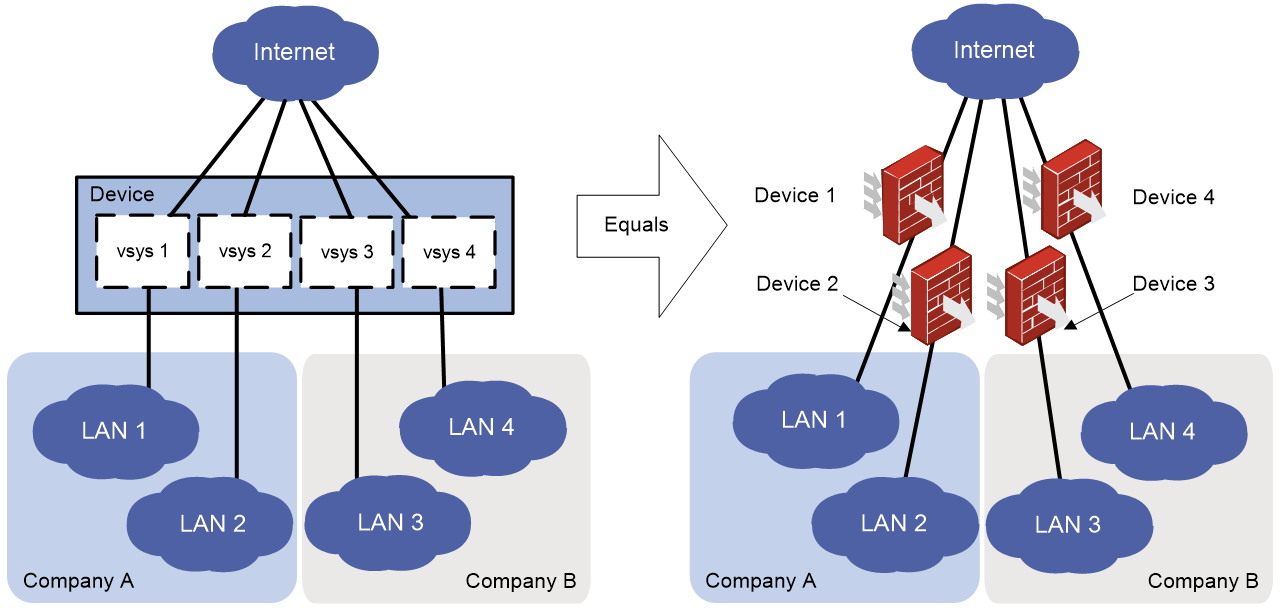
As shown in Figure 1, vSystem is a virtualization technology that divides one physical device into multiple independent logical devices called vSystems. vSystems provide the following benefits:
· vSystems can make effective use of device hardware resources. A single device can provide independent services for multiple organizations, reducing energy consumption and management costs.
· vSystems can be managed by a unified root system administrator or independent vSystem administrators. The administrators have clear responsibilities and can manage vSystems flexibly.
· Each vSystem has independent service settings and route entries. Users with overlapping address spaces can still communicate with one another.
· Each vSystem has fixed interfaces, VLAN resources, and other resource constraints. Busy vSystems do not affect other vSystems.
· The traffic of one vSystem is isolated from that of another vSystem. Traffic forwarding is secure. When necessary, vSystems can also conduct secure mutual visits.
· vSystems consume less device resources and is suitable for large-scale deployment.
Figure 1 vSystem network diagram
Implementation
For massive vSystem construction, the vSystem technology has breakthroughs in the following aspects:
· Management virtualization.
· Resource virtualization.
· Service virtualization.
· vSystem forwarding mechanisms.
Management virtualization
Management interface virtualization
The vSystem technology creates independent management interfaces for all non-default vSystems, including CLIs, Web interfaces, and NETCONF interfaces. These interfaces have the same presentation and usage methods as those on a physical device. No extra operations are required when users use these interfaces on non-default vSystems. This ensures the configuration universality and maintainability of vSystems.
Management role virtualization
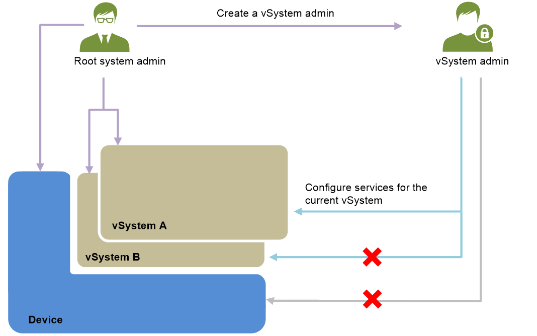
As shown in Figure 2, the vSystem technology realizes flexible management role authorization and clear division of management rights and responsibilities through a two-level management system. The management system contains the following management roles:
· Root system administrator (network-admin)—Responsible for creating vSystems, allocating resources to vSystems, and creating vSystem administrators.
· vSystem administrator (vsys-admin)—Responsible for configuring and managing vSystems. A vSystem administrator has only management privileges to its own vSystem. A vSystem administrator of one vSystem cannot log in to another vSystem to view information and configure features.
Figure 2 vSystem management roles
An enterprise that has a large number of branches can use the vSystem technology to manage the branches as follows:
· The root system administrator in the headquarters creates and initializes the vSystems in the branches and assigns privileges to or removes privileges from the vSystem administrators.
· The vSystem administrators in the branches are responsible for configure services and manage devices in their own departments. If necessary, you can also allow the root system administrator in the headquarters to configure and manage the services and devices in the branches.
Resource virtualization
Interface resource virtualization
The root system administrator can allocate the Layer 3 interface and VLAN resources on a physical device to vSystems on demand. When the use requirements of different vSystems change, the root system administrator can reallocate and coordinate these resources to maximize resource utilization.
vSystems use Layer 3 interface and VLAN resources in exclusive mode. Once a Layer 3 interface or VLAN is assigned to a vSystem, other vSystems cannot use this Layer 3 interface or VLAN (and its associated VLAN interface).
All resources that are not assigned to non-default vSystems belong to the default vSystem.
Non-interface resource virtualization
Unlike Layer 3 interface and VLAN resources, other resources such as security policies, sessions, and throughput are shared by all vSystems. A vSystem can flexibly apply for table entry resources and bandwidth resources according to the operation status of its own services.
To prevent a vSystem from consuming too many resources and affecting the services of other vSystems, the root system administrator can limit the resources available for each vSystem. When the resource usage (including the number of security policy rules, session establishment rate, maximum number of concurrent sessions, and throughput) on a vSystem reaches the specified upper limit, the vSystem cannot apply for more resources.
Resource reclamation
Interface resources must be manually reclaimed by the root system administrator. For table entries and bandwidth resources, when the resource usage of a vSystem decreases, the released resources can be freely used by other vSystems within their upper limits.
Once the root system administrator deletes a vSystem, all the resources allocated to the vSystem will be released. The resources can be allocated to other vSystems for further use.
Service virtualization
Service isolation
When you create a vSystem, a VPN instance with the same name will be created and the created vSystem will be bound to the VPN instance automatically. The service traffic of that vSystem belongs to the VPN instance. The device treats packets in different vSystems as packets in different VPN instances, and it only needs to start one process for a service in all vSystems.
Configuration isolation
The settings of different vSystems are independent. Settings on one vSystem are unable to interfere with settings on another vSystem. After a vSystem is restarted, its configuration information can be restored accurately.
vSystem uses an idea similar to service isolation for configuration isolation. Specifically, the device maintains only one configuration file for all vSystems. The configurations of different vSystems are saved in different sections of the file. When a vSystem runs, it cannot obtain the configurations of other vSystems. After the physical device is restarted, the configuration information of each vSystem will be restored according to the settings in the corresponding sections.
The root system administrator can view and export the configuration information of all vSystems, while a vSystem administrator can only view and export the configuration information of the current vSystem.
Log isolation
Each vSystem generates and outputs log messages independently during operation. The log messages contain the IDs of the vSystems that output them. After service deployment, you can choose to output the log messages of multiple vSystems to different log servers. You can also choose to output them to the same log server without worrying about confusion.
vSystem forwarding mechanisms
Layer 2 forwarding
In a Layer 2 network environment, different branches of an enterprise use VLAN to divide the network. By assigning different VLANs to the vSystems in different branches, the network can forward frames in different branches to the vSystems of the corresponding branches for processing.
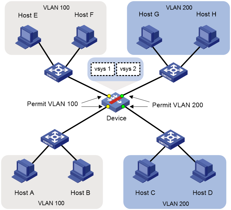
After receiving frames, the device identifies the VLAN to which the frames belong according to the VLAN tag in the header of the frames. Then, the device forwards the frames to the corresponding vSystem according to the bindings between VLANs and vSystems. After the frames reaches the vSystem, the vSystem looks up the MAC address table for the output interface, obtains the inter-zone relationship of the frame input and output interfaces, and then performs security detection and security control on the frames according to the security policies configured on the vSystem.
As shown in Figure 3, Host A, Host B, Host E, and Host F belong to VLAN 100, and Host C, Host D, Host G, and Host H belong to VLAN 200. Assign VLAN 100 to vSystem vsys1 and VLAN 200 to vSystem vsys2, so vSystem vsys1 processes traffic between Host A (or Host B) and Host E (or Host F) and vSystem vsys2 processes traffic between Host C (or Host D and Host G (or Host H).
Figure 3 vSystem support for Layer 2 forwarding
Layer 3 forwarding
In a Layer 3 network environment, branches of an enterprise are divided into multiple network segments. By assigning the interfaces connecting the device to the networks of different branches to the vSystem of each department, packets from different branches will be sent to the vSystems of their corresponding departments for routing table lookup, security policy processing, and packet forwarding.
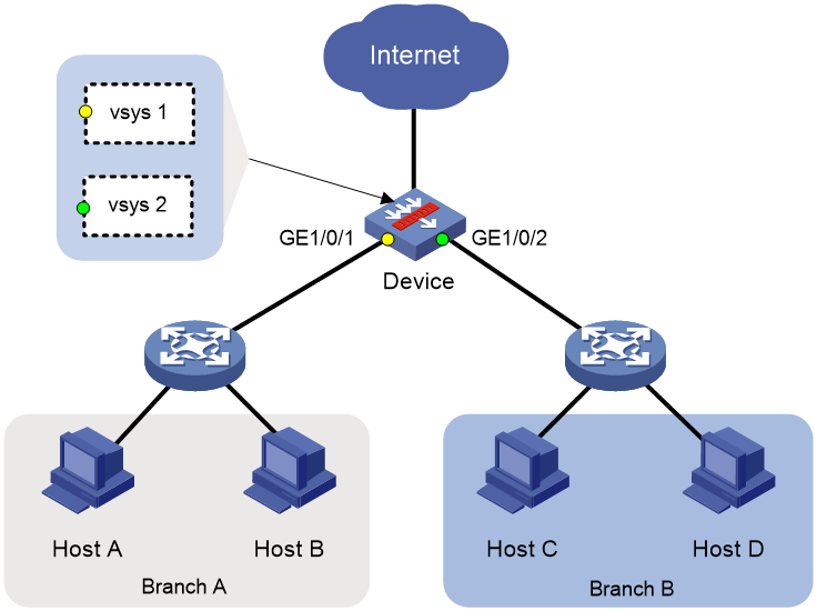
As shown in Figure 4, services in branches A and B are independent. And they have different security defense requirements. You need to create a vSystem to act as a security gateway for each of the branches. To ensure that hosts in the branch networks can access the Internet, you must assign GE 1/0/1 (the interface connected to Branch A) to vSystem vsys1 and assign GE 1/0/2 (the interface connected to Branch B) to vSystem vsys2. In addition, configure routes destined for the external network and security policies on vSystems vsys1 and vsys2.
Figure 4 vSystem support for Layer 3 forwarding
Inter-vSystem communication
vSystem interface
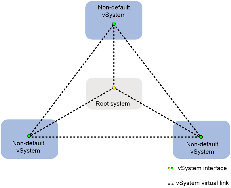
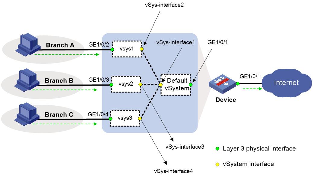
As shown in Figure 5, inter-vSystem communication can be performed through vSystem interfaces. Each vSystem has a vSystem interface, which is always in up state. To ensure that a vSystem interface can operate correctly, you must configure an IP address for it and assign it to a security zone. A vSystem interface is named in the format of vSys-interface interface-number, in which the interface-number portion is the same as the ID of the vSystem. For example, the vSystem interface on the root system is vSys-interface 1. The ID of the root system is 1, and the IDs of non-default vSystems increase in turn according to their creation order.
A virtual link exists between each pair of vSystem interfaces. On one vSystem, you can configure route destined for the vSystem interface of another vSystem for accessing users in the latter vSystem.
Figure 5 vSystem interface network diagram
In a real network, inter-vSystem communications include the following scenarios:
· Communication between a non-default vSystem and the default vSystem.
· Communication between non-default vSystems.
Communication between a non-default vSystem and the default vSystem
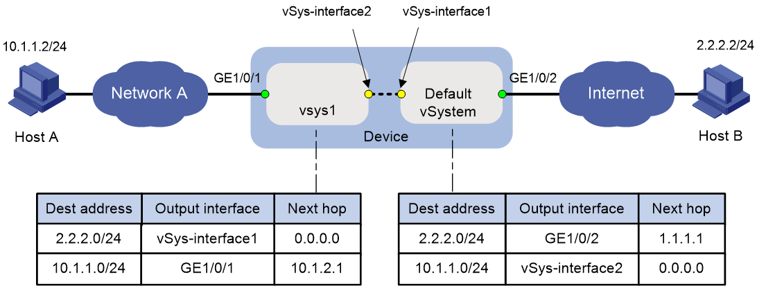
As shown in Figure 6, the root system administrator creates vSystem vsys1 on the device and assign interface GE 1/0/1 to vSystem vsys1. Interface GE 1/0/2 still belongs to the default vSystem. vSys-interface 1 and vSys-interface 2 are the vSystem interfaces of the default vSystem and vSystem vsys1, respectively. For Host A in vSystem vsys1 to communicate with Host B in the default vSystem, you must configure forward and backward routes as follows on the default vSystem and vSystem vsys1:
· Forward routes—On vSystem vsys1, configure a static route destined for 2.2.2.2/32. The output interface is vSys-interface 1 and the next hop is 0.0.0.0. On the default vSystem, configure a static route destined for 2.2.2.0/24. The output interface is GE 1/0/2 and the next hop is 1.1.1.1 (IP address of the interface connected to interface GE 1/0/2).
· Backward routes—On the default vSystem, configure a static route destined for 10.1.1.0/24. The output interface is vSys-interface 2 and the next hop is 0.0.0.0. On vSystem vsys1, configure a static route destined for 10.1.1.0/24. The output interface is GE 1/0/1 and the next hop is 10.1.2.1 (IP address of the interface connected to interface GE 1/0/1).
In addition, you must configure the following security zone and security policy settings on vSystem vsys1 and the default vSystem:
· Security zone settings—On vSystem vsys1, add interface GE 1/0/1 to security zone Trust and add interface vSys-interface 2 to security zone Untrust. On the default vSystem, add interface GE 1/0/2 to security zone Untrust and add interface vSys-interface 1 to security zone Trust.
· Security policy settings—On vSystem vsys1 and the default vSystem, create the following security policies:
¡ Security policy that allows Host A in security zone Trust to access Host B in security zone Untrust.
¡ Security policy that allows Host B in security zone Untrust to access Host A in security zone Trust.
Figure 6 Communication between a non-default vSystem and the default vSystem
When Host A accesses Host B, the packets are forwarded in the following process:
1. Host A sends packets to Host B.
2. When the first packet reaches the device, the device distributes the packet based on the packet incoming interface and forwards the packet to vSystem vsys1. vSystem vsys1 processes the packet as a firewall, including matching the blocklist, looking up for a route, performing NAT, and matching a security policy. If vSystem vsys1 does not permit to forward the packet, it drops the packet and stops the process for forwarding packets from Host A to Host B. If vSystem vsys1 permits to forward the packet, it forwards the packet to the default vSystem through the virtual link between vSys-interface 2 and vSys-interface 1 and establishes a session for subsequent packets on vSystem vsys1.
3. When vSys-interface 1 on the default vSystem receives the packet, the default vSystem processes the packet as a firewall. If the default vSystem does not permit to forward the packet, it drops the packet and stops the process for forwarding packets from Host A to Host B. If the default vSystem permits to forward the packet, it forwards the packet to Host B and establishes a session for subsequent packets on the default vSystem.
4. The packet reaches Host B after routing. Host B sends a response packet to Host A.
5. When the response packet reaches the device, the device uses the same process to forward the response packet to Host A.
Communication between non-default vSystems
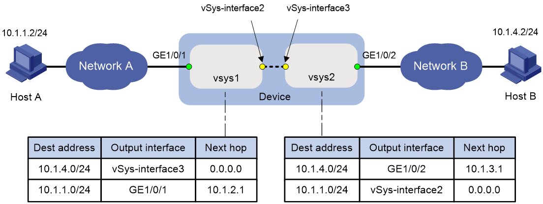
As shown in Figure 7, the root system administrator creates vSystems vsys1 and vsys2 on the device, assigns interface GE 1/0/1 to vSystems vsys1, and assigns interface GE 1/0/2 to vSystem vsys2. vSys-interface 2 and vSys-interface 3 are the vSystem interfaces of vSystems vsys1 and vsys2, respectively. For Host A in vSystem vsys1 to access Host B in vSystem vsys2, you must configure forward and backward routes as follows on vSystems vsys1 and vsys2:
· Forward routes—On vSystem vsys1, configure a static route destined for 2.2.2.2/32. The output interface is vSys-interface 3 and the next hop is 0.0.0.0. On vSystem vsys2, configure a static route destined for 10.1.4.0/24. The output interface is GE 1/0/2 and the next hop is 10.1.3.1 (IP address of the interface connected to interface GE 1/0/2).
· Backward routes—On vSystem vsys2, configure a static route destined for 10.1.1.0/24. The output interface is vSys-interface 2 and the next hop is 0.0.0.0. On vSystem vsys1, configure a static route destined for 10.1.1.0/24. The output interface is GE 1/0/1 and the next hop is 10.1.2.1 (IP address of the interface connected to interface GE 1/0/1).
In addition, you must configure the following security zone and security policy settings on vSystems vsys1 and vsys2:
· Security zone settings—On vSystem vsys1, add interface GE 1/0/1 to security zone Trust and add vSys-interface 2 to security zone DMZ. On vSystem vsys2, add interface GE 1/0/2 to security zone Trust and add vSys-interface 3 to security zone DMZ.
· Security policy settings—On vSystem vsys1, create a security policy to allow Host A in security zone Trust to access Host B in security zone DMZ. On vSystem vsys2, create a security policy to allow Host B in security zone Trust to access Host A in security zone DMZ.
Figure 7 Communication between non-default vSystems
When Host A accesses Host B, the packets are forwarded in the following process:
1. Host A sends packets to Host B.
2. When the first packet reaches the device, the device distributes the packet based on the packet incoming interface and forwards the packet to vSystem vsys1. vSystem vsys1 processes the packet as a firewall, including matching the blocklist, looking up for a route, performing NAT, and matching a security policy. If vSystem vsys1 does not permit to forward the packet, it drops the packet and stops the process for forwarding packets from Host A to Host B. If vSystem vsys1 permits to forward the packet, it forwards the packet to vSystem vsys2 through the virtual link between vSys-interface 2 and vSys-interface 3 and establishes a session for subsequent packets on vSystem vsys1.
3. When vSys-interface 3 on vSystem vsys2 receives the packet, vSystem vsys2 processes the packet as a firewall. If vSystem vsys2 does not permit to forward the packet, it drops the packet and stops the process for forwarding packets from Host A to Host B. If vSystem vsys2 permits to forward the packet, it forwards the packet to Host B and establishes a session for subsequent packets on vSystem vsys2.
4. The packet reaches Host B after routing. Host B sends a response packet to Host A.
5. When the response packet reaches the device, the device uses the same process to forward the response packet to Host A.
Application scenarios
Large- and medium-sized enterprise network isolation
As shown in Figure 8, the internal network of an enterprise is divided into multiple areas based on departments. Each area has its own Internet access requirements. In order to provide customizable security gateway services for each department, you can create a vSystem for each area on the device that acts as the enterprise egress gateway and use the vSystems as the security gateway of each area. When users in an area access the Internet, the access packets will be processed by the gateway vSystem in the area and the root system in turn, and finally forwarded to the Internet through the public network interface of the root system.
Figure 8 Network diagram for large- and medium-sized enterprise network isolation
Cloud security gateway
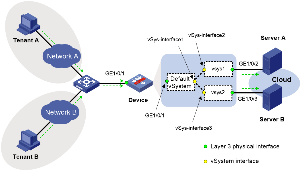
As shown in Figure 9, Tenant A and Tenant B in the public network rent servers in the cloud center. The cloud center provides independent protection for cloud assets deployed by Tenant A and Tenant B. For this purpose, create vSystems on the egress gateway Device to act as security gateways for the tenants. When a tenant accesses its cloud assets, the access packets pass through the default vSystem and the vSystem that acts as the security gateway for the tenant. The latter vSystem forwards the packets to the cloud network through a private network interface.
Figure 9 Cloud security gateway network diagram