Stateful failover system
About stateful failover
For high availability, you can set up a stateful failover system with two hosts to prevent hardware or software failure from interrupting services. In the stateful failover system, one host is placed in primary state to provide services, and the other host is placed in backup state as a standby. The primary host synchronizes database files to the backup host over the management network in real time. When the primary host fails, the backup host takes over automatically to ensure service continuity.
You can create a local synchronization partition on both the primary and secondary nodes to synchronize the data other than database files.
Stateful failover supports the following deployment modes:
Converged deployment—The primary and backup nodes are in a service cluster, such as a compute, network, or storage cluster, as shown in Figure 1.
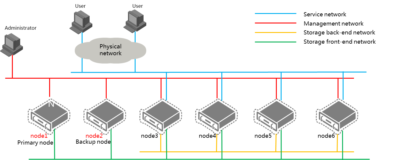
Distributed deployment—The primary and backup nodes are independent nodes not in a service cluster, as shown in Figure 2.
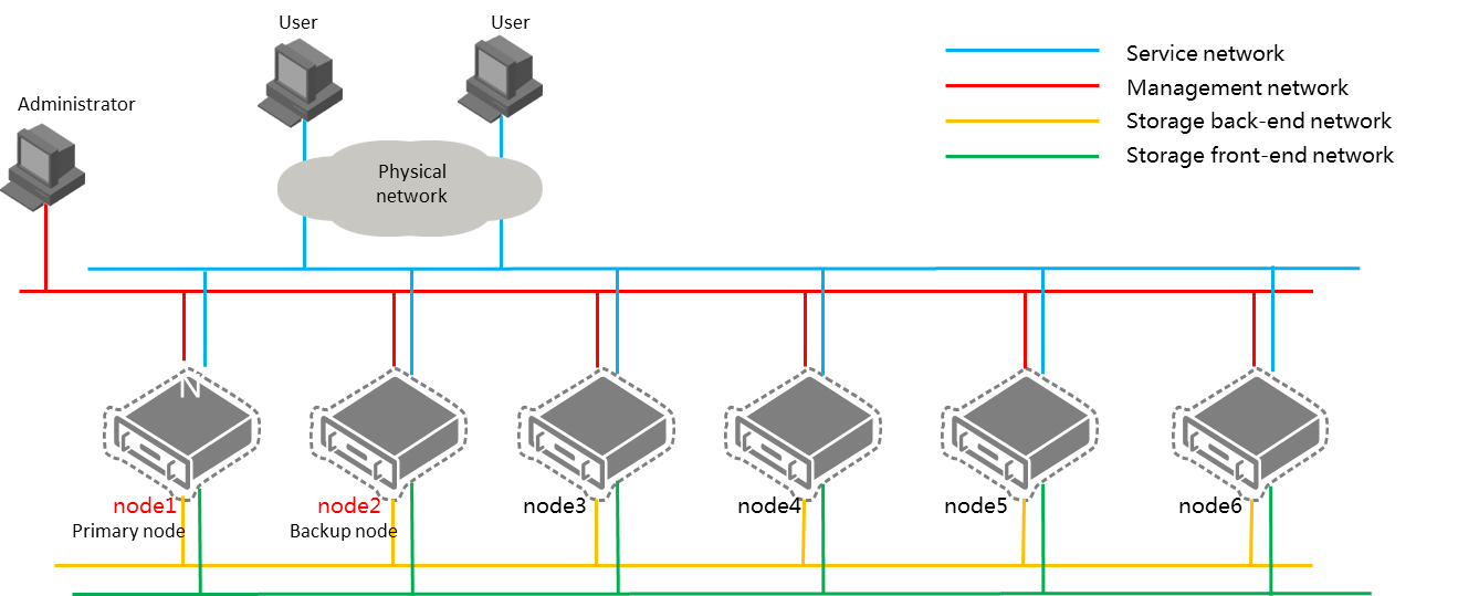
Figure-2 Distributed deployment
Prerequisites
Make sure the two management hosts for stateful failover meet the following requirements:
The hosts have the same hardware configuration.
You can set up a stateful failover system only when deploying Space Console. Make sure no CVK hosts are incorporated, and no VMs exist.
The storage pools on the hosts use the default settings after initialization. The hosts only have default storage pools isopool and defaultpool.
The hosts use the same Space Console version, boot mode, and boot drive.
The two hosts have the same system time.
The vms partition has at least 20GB storage space.
The management networks of the two hosts are reachable to each other.
The following settings on the two hosts are exactly the same:
Number of system disks and disk sizes.
RAID configuration.
Extended partitions, including their names and sizes.
Restrictions and guidelines
You must set up a stateful failover system in an HCI environment.
Stateful failover system setup fails when desktop image storage or course storage is in use by other applications.
Do not perform any operations during a primary/backup switchover.
You can set up a stateful failover system only when deploying Space Console. You cannot set up a stateful failover system for deployed Space Console because data of deployed Space Console is cleared in stateful failover system setup.
You cannot split a stateful failover system into two independent Space Console platforms.
Make sure both management hosts are in or not in a service cluster.
As a best practice to save the management network bandwidth, use FC or iSCSI shared directories as template pools to synchronize desktop image templates.
If the stateful failover system splits because of network anomalies, the nodes in the system automatically elect the primary node after the network recovers. If service hosts are sending performance statistics to the backup node when the split-brain failure occurs, the hosts will still send performance statistics to the backup node after the stateful failover system recovers, which causes data loss on the primary node. To resolve this issue, you must connect the service hosts to the primary Space Console platform.
Do not modify the hostname or IP address of a management node after the stateful failover system is set up. If you do so, data loss will occur.
To add member nodes of a stateful failover system as CVK hosts, make sure Space Console has not been upgraded on the nodes.
If you use an NVMe drive as the system disk, stateful failover is not supported, and you need to manually configure RAID for the hard disk. As a best practice, configure RAID 1 for two NVMe drives before installation, and use the manual installation method.
Set up a stateful failover system
Procedure
|
|
· During the setup process of the stateful failover system, do not access the /vms directory through SSH. If you do so, stateful failover system setup fails. · During the setup process of the stateful failover system, do not reboot or shut down a management node. If a management node reboots or shuts down unexpectedly, you must set up the stateful failover system again. · To avoid unexpected errors, do not modify the host names or IP addresses after the stateful failover system is set up. · Make sure hosts for setting up a stateful failover system have the same IP type (IPv4 or IPv6) as the network type planned by Space Console. |
From the navigation pane, select System > Failover System Management > Stateful Failover System.
Click Set Up Stateful Failover System.
Configure the parameters as described in "Parameters."
Click OK.
Parameters
Virtual IP Address: Specify the IP address for accessing Space Console. It must be an IP address not in use.
Subnet Mask: Specify the subnet mask for the virtual IP address.
Storage Component Virtual IP: Specify the virtual IP address used for high availability management of the distributed storage system. The virtual IP address can be automatically assigned or manually configured. It must be an unused IP address in the management network. This parameter is available only in a converged deployment environment.
Backup Host Location: Specify the location of the backup host.
Host in System—A host in a service cluster, such as a compute, network, or storage cluster. Select this option in a converged deployment environment.
Others—A host not in a service cluster. Select this option in a distributed deployment environment.
Backup Host IP: Specify the management IP address of the backup Space Console. This parameter is available if the backup host is in a service cluster.
Select Backup Host: Select the backup host by its IP address. This parameter is available if the backup host is not in a service cluster.
Backup Host IP: IP address of the backup host. This parameter is automatically populated with the IP address of the selected backup host. This parameter is available if the backup host is not in a service cluster.
Quorum Mode: Select a quorum mode. Options include Advanced and Ping.
Advanced—When the primary and backup hosts cannot communicate with each other, they send their respective state information to the quorum host. The quorum host determines the role of each node and sends the role information to the nodes. The quorum host must have Space Console installed. As a best practice, use a host in the cluster as a quorum host.
Ping—When the primary and backup hosts cannot communicate with each other, they ping the quorum IP addresses. If a node fails to ping any quorum IP address, the node determines that it has network failures and becomes a backup node.
Quorum Host IP: Specify the IP address of the quorum host.
Quorum Host Root PWD: Enter the root password of the quorum host.
Quorum IP Address: Specify the IP address of a gateway that can be accessed or the IP address of a host that is always reachable. The quorum IP address is used to check the network connectivity of the hosts. As a best practice, specify the IP address of a gateway. You must specify two different quorum IP addresses if you select the Ping quorum mode.
Estimated Host Quantity: Enter the estimated number of hosts in Space Console for calculating the database partition size.
Estimated VM Quantity: Enter the estimated number of VMs in Space Console for calculating the database partition size.
Database Partition Size: Specify the database partition size. The database partition is used for data synchronization between the primary and backup hosts and is part of the /vms partition. Database partition size (in MB) = (Estimated host quantity × 7 MB + estimated VM quantity × 5 MB) × 15 days / 1024 MB. The database partition size cannot be smaller than 20 GB.
Display stateful failover settings
From the navigation pane, select System > Failover System Management > Stateful Failover System.
Click View Stateful Failover Settings.
Perform manual primary/backup switchover
|
|
· For successful primary/backup switchover, make sure the primary and backup nodes have consistent data. · Do not perform a manual primary/backup switchover when the backup node is abnormal, data synchronization is in progress, or data synchronization is abnormal. · Perform a manual primary/backup switchover when services are suspended or services do not have traffic. Users cannot set up new desktop connections during the switchover. Connected desktops are not affected. |
From the navigation pane, select System > Failover System Management > Stateful Failover System.
Click Primary/Backup Switchover.
Click OK.
Configure the virtual IP address of the service network
Perform this task if the management network and the service network are isolated and the VM network is on the service network in a stateful failover system. This task ensures that VMs on the service network can correctly communicate with the management platform after primary/backup switchover.
From the navigation pane, select System > Failover System Management > Stateful Failover System.
Click Configure Service Network VIP.
In the dialog box that opens, select a vSwitch and then specify the virtual IP address and subnet mask of the service network.
Make sure the virtual IP address of the service network and the service network IP addresses of the vSwitches of the primary and standby management nodes are on the same network segment.
Click OK.
Display stateful failover host information
This task is available in a distributed deployment environment.
Procedure
From the navigation pane, select System > Failover System Management > Stateful Failover System.
If a host is not in a service cluster, the system displays the Network and Storage Adapters tabs for the host.
Manage the vSwitches of the host on the Network tab. You can add, modify, or delete vSwitches.
Manage the storage adapters of the host on the Storage Adapters tab. You can modify the IQN or scan storage devices.
Parameters
Network parameters:
Network Type: Select a network type for the virtual switch.
Mgmt—Transmits the management data between the management platform and the hosts.
Service—Transmits the service data for VMs.
Storage—Transmits packets between hosts and the distributed storage system or the IP SAN storage server. This type of virtual switches cannot be used by VMs.
Backup—Transmits the backup data of VMs. A host can have only one virtual switch of this type and the virtual switch cannot be used by VMs.
Migration—Transmits the data for migrating VMs. A host can have only one virtual switch of this type and the virtual switch cannot be used by VMs.
Others—Transmits other kinds of data.
Physical Interface: Uplink interface on the physical NIC used by the virtual switch.
Forwarding Mode: Select a forwarding mode for the virtual switch. Only the Virtual Ethernet Bridge (VEB) mode is supported in the current software version. In this mode, traffic between VMs is forwarded through the software.
VLAN ID: Enter the VLAN ID of the interface connected to the protocol stack of the host.
State: State of the virtual switch.
IP: IP address of the virtual switch.
Mask/Prefix: Subnet mask/prefix of the virtual switch.
Gateway: Gateway of the virtual switch.
Bandwidth Ratio: Bandwidth ratios of different networks when they use the same physical interface. For example, the bandwidth of an interface is 10000 Mbps, and both the storage front-end network and the storage back-end network use the interface. If the bandwidth ratio of the storage back-end network is 60%, the maximum bandwidth of the network is 6000 Mbps.
DPDK State: DPDK state of the virtual switch.
Storage adapter parameters:
Name: Storage adapter Name.
Model: Storage adapter model.
Type: Storage adapter type.
State: Storage adapter state.
IQN: Storage adapter identifier.
Normal Scanning: Scans devices by following normal scanning rules.