Manage virtual switches
A virtual switch provides software-based switching between VMs, hosts, and the external network.
UIS provides standard and accelerated vSwitches. A standard vSwitch uses a NIC that does not have acceleration functions. Accelerated vSwitches include DPDK-accelerated vSwitches (created on DPDK-enabled hosts) and smart NIC-accelerated vSwitches.
Virtual switch logical topology
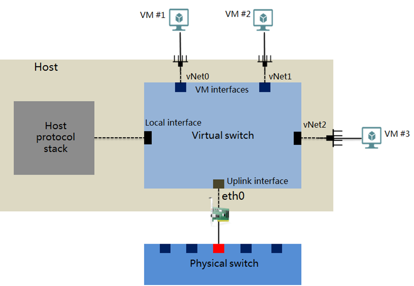
Virtual switch interfaces
A virtual switch provides the following interfaces:
VM interface—An interface that connects to the virtual NIC of a VM for the VM to communicate with other VMs or the external network.
Local interface— An interface that connects to the protocol stack on the host.
Uplink interface— An interface that connects to the physical NIC of the host.
Restrictions and guidelines
Virtual switches being used by VMs cannot be deleted.
After you add or delete a virtual switch with a network type of service network, the virtual switch will also be added to or removed from the network topology.
Editing virtual switch settings might cause network failures. Please be cautious. Before you edit a vSwitch, make sure no services are running on the vSwitch and the related settings on the physical switch are also edited.
Suspended virtual switches cannot provide services. To avoid service interruption, make sure a virtual switch is not being used before suspending the virtual switch.
If you cannot select a smart NIC when you create a smart NIC-accelerated vSwitch on a host, enable HugePages on the host and reboot it.
Editing the management network IP of a host might cause connectivity issues between the host and the cluster network and affect services. Before editing the management network IP of a host, stop all services on the host, suspend and delete the storage pool, and delete the host from the cluster. For more information, contact the technical support.
Add a virtual switch
On the top navigation bar, click Cloud Resources, and then select Network > vSwitches from the navigation pane.
Set the parameters as described in "Parameters."
Click Finish.
Edit a virtual switch
On the top navigation bar, click Cloud Resources, and then select Network > vSwitches from the navigation pane.
Click the Edit icon
 for a virtual switch.
Edit the parameters as described in "Parameters."
Click Finish.
Delete virtual switches
On the top navigation bar, click Cloud Resources, and then select Network > vSwitches from the navigation pane.
Click the Delete icon
 for a virtual switch.
In the dialog box that opens, click OK.
View the topology for a virtual switch
On the top navigation bar, click Cloud Resources, and then select Network > vSwitches from the navigation pane.
Click the View Topology icon
 for a virtual switch to view its topology.
Detach a host from a virtual switch
On the top navigation bar, click Cloud Resources, and then select Network > vSwitches from the navigation pane.
Click the Delete vSwitch from Host icon
 for a host in the Attached Hosts area.
In the dialog box that opens, click OK.
Parameters
Network Type: Select a network type for the virtual switch.
Management—Transmits the control layer data between UIS Manager and the hosts.
Service—Transmits VM service data.
Storage—Transmits data between the hosts and storage servers. This type of virtual switches cannot be used by VMs.
Backup—Transmits the backup data of VMs. A host can have only one virtual switch of this type, and the virtual switch cannot be used by VMs. If you do not configure an independent backup network switch, the system transmits backup data through management network switch vswitch0.
Migration—Transmits the data for migrating VMs. A host can have only one virtual switch of this type, and the virtual switch cannot be used by VMs. If you do not configure an independent migration network switch, the system transmits migration data through management network switch vswitch0.
Others—Transmits other kinds of data.
Forwarding Mode: Select a forwarding mode for the virtual switch. Only VEB is available.
VEB—In Virtual Ethernet Bridge (VEB) mode, the traffic between VMs is forwarded through the software.
VLAN ID: Enter the VLAN ID of the interface connected to the protocol stack of the host.
Acceleration: State of the acceleration feature. This field displays Smart NIC for a smart NIC-accelerated vSwitch and DPDK for a DPDK-accelerated vSwitch. For a standard vSwitch, this field is empty.
MTU: Set the maximum packet length that the virtual switch allows, in bytes.
Multicast: Set the state of multicast forwarding.
DPDK: Configure whether to enable DPDK or not. Enabling DPDK can improve the network performance of the VM.
NIC Type: Select Physical Interfaces for a standard vSwitch, and select Smart NIC for a smart NIC-accelerated vSwitch. A smart NIC offers high forwarding performance without using the compute resources of a host. To create a smart NIC-accelerated virtual siwtch on a host, install a smart NIC and enable HugePages on the host.
Select Interfaces: Select interfaces on NICs.
Physical Interfaces: Select the physical interfaces used by the virtual switch. A physical interface can be used by only one virtual switch. This parameter is unavailable if all physical interfaces on the hosts have been used. If no physical interface is configured for a virtual switch, VMs connected to the virtual switch can only communicate with each other, not with the external network. If you select multiple physical interfaces, you must configure the link aggregation mode and load balancing mode.
Intelligent NIC: Select one or two physical interfaces. If you select two physical interfaces, make sure the two interfaces are on the same intelligent NIC.
IP: Enter an IP address for the virtual switch.
Subnet Mask: Enter the subnet mask of the IP address.
Gateway: Enter a gateway address for the virtual switch.
Linux Link Aggregation: Configure how to aggregate the links between the smart NIC and a physical switch and distribute traffic on the aggregate link.
Active/Backup—Balances load based on the active and backup roles of physical interfaces. If the active interface fails, traffic is automatically switched to the backup interface.
XOR—Balances load based on the source and destination MAC addresses by using the XOR algorithm. In this mode, configure link aggregation and disable negotiation on the physical switch to ensure that specific flows are forwarded by the same interface.
LACP—Runs IEEE 802.3ad LACP to dynamically aggregate the links. In this mode, you must configure dynamic link aggregation on the physical switch.
LAGG Mode: Select a link aggregation mode for the physical NICs. Options include Static and Dynamic. As a best practice, use dynamic link aggregation mode. If you select the dynamic link aggregation mode, you must enable LACP on the physical switch. This parameter is available only when you select multiple physical interfaces.
LB Mode: Select the load balancing mode for physical NICs on the virtual switch. This parameter is available only when you select multiple physical interfaces.
Advanced—Performs load balancing based on Ethernet type, IP protocol, source IP address, destination IP address, source port, and destination port of the packets. As a best practice, use advanced load balancing mode in an environment that requires precise load balancing.
Basic—Performs load balancing based on the source MAC address and VLAN tag of the packets.
Primary/Backup—Performs load balancing based on the primary and backup physical NICs. When the primary NIC fails, the system automatically switches the traffic to the backup NIC. This option is available only when the link aggregation mode is Static.
Fallback: Select whether to switch services from the backup NIC back to the primary NIC after the primary NIC recovers. This parameter is required when the load balancing mode is Primary/Backup.
Primary NIC Selection: Select the method used to select the primary NIC. This parameter is required when the load balancing mode is Primary/Backup.
Rate-Based: The system automatically selects the primary NIC based on the rates of the NICs. The NIC with the highest rate becomes the primary NIC. When multiple NICs have the same rate, the system randomly selects a NIC as the primary NIC.
Manual: You specify the primary NIC by arranging the LB priorities of the NICs. The NIC with the highest priority is the primary NIC. You must configure the LB priorities for the NICs in this mode.
LB Priority: Arrange the NICs to define their LB priorities. The NIC on the top has the highest priority and is the primary NIC.
Host Name: Enter the name of the host to which the virtual switch is attached.