- Table of Contents
- Related Documents
-
| Title | Size | Download |
|---|---|---|
| 01-EVPN configuration | 1.37 MB |
Contents
Restrictions: Hardware compatibility with EVPN features
Assignment of traffic to VXLANs
Traffic from the local site to a remote site
Traffic from a remote site to the local site
Centralized EVPN gateway deployment
Distributed EVPN gateway deployment
RD and route target selection of BGP EVPN routes
Hardware compatibility with EVPN multihoming
Hardware compatibility with EVPN multicast
Multicast in single-homed sites
Restrictions: Hardware compatibility with EVPN gateways
Restrictions and guidelines: EVPN configuration
Setting the VXLAN hardware resource mode
Setting the VXLAN hardware resource mode (S6800 and S6860 switch series)
Setting the VXLAN hardware resource mode (S6820 switch series)
Restrictions and guidelines for VXLAN configuration on a VSI
Restrictions and guidelines for EVPN multihoming
Hardware compatibility with EVPN multihoming
Assigning an ESI to an interface
Disabling advertisement of EVPN multihoming routes
Configuring BGP to advertise BGP EVPN routes
Restrictions and guidelines for BGP EVPN route advertisement
Enabling BGP to advertise BGP EVPN routes
Configuring optimal route selection and route advertisement settings
Mapping a static Ethernet service instance to a VSI
Mapping dynamic Ethernet service instances to VSIs
Configuring a centralized EVPN gateway
Configuring a distributed EVPN gateway
Restrictions and guidelines for distributed EVPN gateway configuration
Prerequisites for distributed EVPN gateway configuration
Configuring an L3 VXLAN ID for a VSI interface
Configuring IP prefix route advertisement
Configuring the EVPN global MAC address
Disabling generation of IP prefix advertisement routes for the subnets of a VSI interface
Managing remote MAC address entries and remote ARP or ND learning
Disabling remote MAC address learning and remote ARP or ND learning
Disabling MAC address advertisement
Disabling learning of MAC addresses from ARP or ND information
Disabling ARP information advertisement
Enabling ARP mobility event suppression
Enabling conversational learning for forwarding entries
About conversational learning for forwarding entries
Restrictions and guidelines for enabling conversational learning for forwarding entries
Enabling conversational learning for remote MAC address entries
Enabling conversational learning for host route FIB entries
Configuring BGP EVPN route redistribution and advertisement
Redistributing MAC/IP advertisement routes into BGP unicast routing tables
Enabling BGP EVPN route advertisement to the local site
Enabling ARP or ND flood suppression
Enabling packet statistics for VXLAN tunnels
Configuring EVPN distributed relay
Display and maintenance commands for EVPN
Example: Configuring a centralized IPv4 EVPN gateway
Example: Configuring distributed IPv4 EVPN gateways (IPv4 underlay network)
Example: Configuring distributed IPv6 EVPN gateways (IPv4 underlay network)
Example: Configuring communication between IPv4 EVPN networks and the public network
Example: Configuring IPv4 EVPN distributed relay using an Ethernet aggregate link as the IPL
Example: Configuring IPv4 EVPN distributed relay using a VXLAN tunnel as the IPL (with Monitor Link)
Example: Configuring IPv4 EVPN multihoming
Example: Configuring EVPN multicast
Restrictions: Hardware compatibility with EVPN-DCI
Restrictions and guidelines: EVPN-DCI configuration
Enabling route nexthop replacement and route router MAC replacement
Enabling an ED to replace the L3 VXLAN ID and RD of IP prefix advertisement routes
Suppressing BGP EVPN route advertisement
Configuring the BGP EVPN address family and the BGP VPNv4 or VPNv6 address family to exchange routes
Enabling BGP VPNv4 or VPNv6 route advertisement for the BGP EVPN address family
Enabling BGP EVPN route advertisement for the BGP VPNv4 or VPNv6 address family
Configuring EVPN-DCI dual-homing
EVPN-DCI configuration examples
Example: Configuring a basic EVPN-DCI network (IPv4 underlay network)
Example: Configuring EVPN-DCI intermediate VXLAN mapping (IPv4 underlay network)
Example: Configuring EVPN-DCI Layer 3 communication (IPv4 sites+IPv4 underlay network)
Example: Configuring EVPN-DCI Layer 3 communication (IPv6 sites+IPv4 underlay network)
Example: Configuring EVPN-DCI dual-homing (IPv4 sites+IPv4 underlay network)
EVPN overview
Ethernet Virtual Private Network (EVPN) is a Layer 2 VPN technology that provides both Layer 2 and Layer 3 connectivity between distant network sites across an IP network. EVPN uses MP-BGP in the control plane and VXLAN in the data plane. EVPN is typically used in data centers for multitenant services.
EVPN provides the following benefits:
· Configuration automation—MP-BGP automates VTEP discovery, VXLAN tunnel establishment, and VXLAN tunnel assignment to ease deployment.
· Separation of the control plane and the data plane—EVPN uses MP-BGP to advertise host reachability information in the control plane and uses VXLAN to forward traffic in the data plane.
· Integrated routing and bridging (IRB)—MP-BGP advertises both Layer 2 and Layer 3 host reachability information to provide optimal forwarding paths and minimize flooding.
Restrictions: Hardware compatibility with EVPN features
The S6861 switch series does not support EVPN.
EVPN multihoming, EVPN gateways, and EVPN-DCI are not supported by S6800 switches labeled with the following product codes:
· LS-6800-2C.
· LS-6800-32Q.
· LS-6800-4C.
EVPN network model
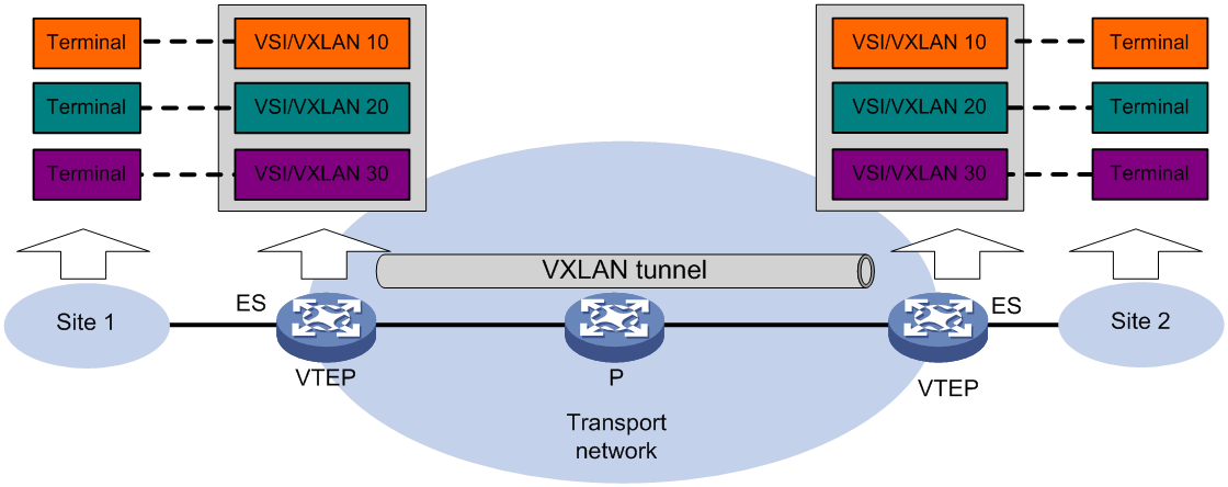
As shown in Figure 1, EVPN uses the VXLAN technology for traffic forwarding in the data plane. The transport edge devices assign user terminals to different VXLANs, and then forward traffic between sites for user terminals by using VXLAN tunnels. The transport edge devices are VXLAN tunnel endpoints (VTEPs).
Supported user terminals include PCs, wireless terminals, and VMs on servers.
|
|
NOTE: This document uses VMs as examples to describe the mechanisms of EVPN. The mechanisms do not differ between different kinds of user terminals. |
A VTEP uses ESs, VSIs, and VXLAN tunnels to provide VXLAN services:
· Ethernet segment (ES)—An ES is a link that connects a site to a VTEP. Each ES is uniquely identified by an Ethernet segment identifier (ESI).
· VSI—A virtual switch instance is a virtual Layer 2 switched domain. Each VSI provides switching services only for one VXLAN. VSIs learn MAC addresses and forward frames independently of one another. User terminals in different sites have Layer 2 connectivity if they are in the same VXLAN. A VXLAN is identified by a 24-bit VXLAN ID which is also called the virtual network identifier (VNI). A VXLAN corresponds to an EVPN instance.
· VXLAN tunnel—Logical point-to-point tunnels between VTEPs over the transport network. Each VXLAN tunnel can trunk multiple VXLANs.
All VXLAN processing is performed on VTEPs. The ingress VTEP encapsulates VXLAN traffic in the VXLAN, outer UDP, and outer IP headers, and forwards the traffic through VXLAN tunnels. The egress VTEP removes the VXLAN encapsulation and forwards the traffic to the destination. Transport network devices (for example, the P device in Figure 1) forward VXLAN traffic only based on the outer IP header of VXLAN packets.
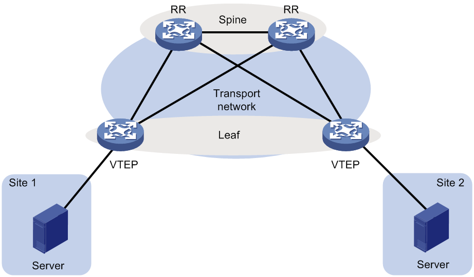
Layered transport network
As shown in Figure 2, typically the EVPN transport network uses a layered structure. On the transport network, leaf nodes act as VTEPs to provide VXLAN services, and spine nodes perform forwarding for VXLAN traffic based on the outer IP header. If all VTEPs and transport network devices of an EVPN network belong to the same AS, the spine nodes can act as route reflectors (RRs) to reflect routes between the VTEPs. In this scenario, the spine nodes advertise and receive BGP EVPN routes, but do not perform VXLAN encapsulation and de-encapsulation.
Figure 2 Layered transport network
MP-BGP extension for EVPN
To support EVPN, MP-BGP introduces the EVPN subsequent address family under the L2VPN address family and the following network layer reachability information (BGP EVPN routes):
· Ethernet auto-discovery route—Advertises ES information in multihomed sites.
· MAC/IP advertisement route—Advertises MAC reachability information and host route information (host ARP or ND information).
· Inclusive multicast Ethernet tag (IMET) route—Advertises VTEP and VXLAN mappings for automating VTEP discovery, VXLAN tunnel establishment, and VXLAN tunnel assignment.
· Ethernet segment route—Advertises ES and VTEP mappings.
· IP prefix advertisement route—Advertises BGP IPv4 or IPv6 unicast routes as IP prefixes.
· Selective multicast Ethernet tag (SMET) route—Advertises IGMP multicast group information among VTEPs in an EVPN network. A VTEP advertises an SMET route only when receiving a membership report for an IGMP multicast group for the first time. The VTEP does not advertise an SMET route if subsequent membership reports for the multicast group use the same IGMP version as the first membership report.
· IGMP join synch route—Advertises IGMP membership reports among redundant VTEPs for an ES.
· IGMP leave synch route—Advertises IGMP leave group messages for withdrawal of IGMP join synch routes among redundant VTEPs for an ES.
MP-BGP uses the route distinguisher (RD) field to differentiate BGP EVPN routes of different VXLANs and uses route targets to control the advertisement and acceptance of BGP EVPN routes. MP-BGP supports the following types of route targets:
· Export target—A VTEP sets the export targets for BGP EVPN routes learned from the local site before advertising them to remote VTEPs.
· Import target—A VTEP checks the export targets of BGP EVPN routes received from remote VTEPs. The VTEP imports the BGP EVPN routes only when their export targets match the local import targets.
Configuration automation
VTEPs use BGP EVPN routes to discover VTEP neighbors, establish VXLAN tunnels, and assign the tunnels to VXLANs.
· IMET route—VTEPs advertise the VXLAN IDs they have through IMET routes. If two VTEPs have the same VXLAN ID, they automatically establish a VXLAN tunnel and assign the tunnel to the VXLAN.
· MAC/IP advertisement route and IP prefix advertisement route—In the EVPN gateway deployment, VTEPs advertise MAC/IP advertisement routes or IP prefix advertisement routes with the export targets. When a VTEP receives a route, it compares the export targets of the route with the local import targets. If the route targets match, the VTEP establishes a VXLAN tunnel with the remote VTEP and associates the tunnel with the L3 VXLAN ID of the corresponding VPN instance. For more information about the L3 VXLAN ID, see "Distributed EVPN gateway deployment."
Assignment of traffic to VXLANs
Traffic from the local site to a remote site
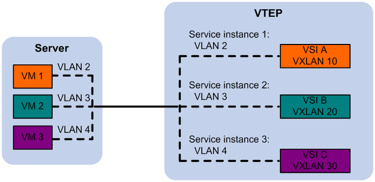
The VTEP uses an Ethernet service instance to match customer traffic on a site-facing interface. The VTEP assigns customer traffic to a VXLAN by mapping the Ethernet service instance to a VSI.
An Ethernet service instance is identical to an attachment circuit (AC) in L2VPN. An Ethernet service instance matches a list of VLANs on a Layer 2 Ethernet interface by using a frame match criterion. The frame match criterion specifies the characteristics of traffic from the VLANs, such as tagging status and VLAN IDs.
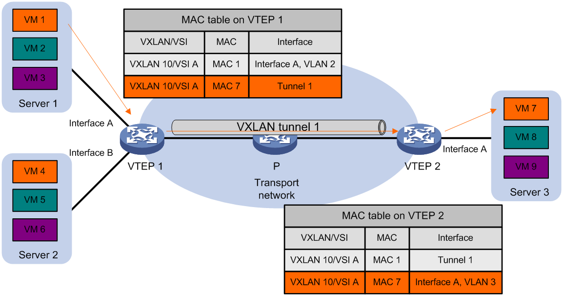
As shown in Figure 3, Ethernet service instance 1 matches VLAN 2 and is mapped to VSI A (VXLAN 10). When a frame from VLAN 2 arrives, the VTEP assigns the frame to VXLAN 10, and looks up VSI A's MAC address table for the outgoing interface.
Figure 3 Identifying traffic from the local site
Traffic from a remote site to the local site
When a VXLAN packet arrives at a VXLAN tunnel interface, the VTEP uses the VXLAN ID in the packet to identify its VXLAN.
Layer 2 forwarding
MAC learning
The VTEP performs Layer 2 forwarding based on a VSI's MAC address table. The VTEP learns MAC addresses by using the following methods:
· Local MAC learning—The VTEP automatically learns the source MAC addresses of frames sent from the local site. The outgoing interfaces of local MAC address entries are site-facing interfaces on which the MAC addresses are learned.
· Remote MAC learning—The VTEP uses MP-BGP to advertise local MAC reachability information to remote sites and learn MAC reachability information from remote sites. The outgoing interfaces of MAC address entries advertised from a remote site are VXLAN tunnel interfaces.
Unicast
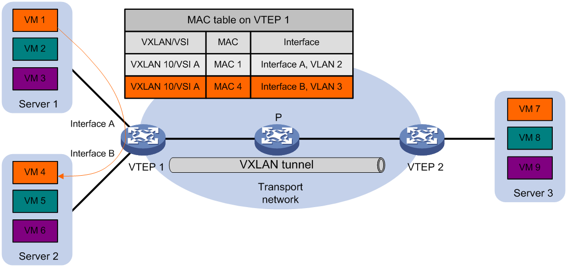
As shown in Figure 4, the VTEP performs typical Layer 2 forwarding for known unicast traffic within the local site.
As shown in Figure 5, the following process applies to a known unicast frame between sites:
1. The source VTEP encapsulates the Ethernet frame in the VXLAN/UDP/IP header.
In the outer IP header, the source IP address is the source VTEP's VXLAN tunnel source IP address. The destination IP address is the VXLAN tunnel destination IP address.
2. The source VTEP forwards the encapsulated packet out of the outgoing VXLAN tunnel interface found in the VSI's MAC address table.
3. The intermediate transport devices (P devices) forward the packet to the destination VTEP by using the outer IP header.
4. The destination VTEP removes the headers on top of the inner Ethernet frame. It then performs MAC address table lookup in the VXLAN's VSI to forward the frame out of the matching outgoing interface.
Flood
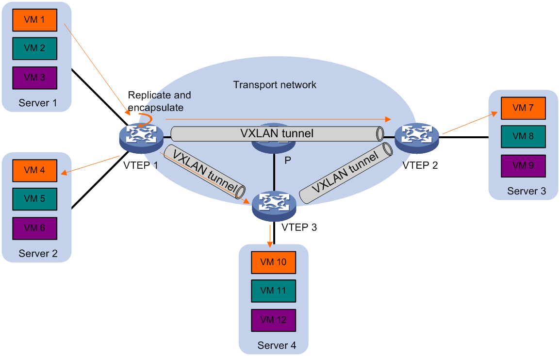
As shown in Figure 6, a VTEP floods a broadcast, multicast, or unknown unicast frame to all site-facing interfaces and VXLAN tunnels in the VXLAN, except for the incoming interface. The source VTEP replicates the flood frame, and then sends one replica to the destination IP address of each VXLAN tunnel in the VXLAN. Each destination VTEP floods the inner Ethernet frame to all the site-facing interfaces in the VXLAN. To avoid loops, the destination VTEPs do not flood the frame to VXLAN tunnels.
Figure 6 Forwarding of flood traffic
Layer 3 forwarding
EVPN uses EVPN gateways to provide Layer 3 forwarding services for hosts in VXLANs. EVPN provides the following EVPN gateway placement designs:
· Centralized EVPN gateway deployment—Use one VTEP to provide Layer 3 forwarding for VXLANs. Typically, the gateway-collocated VTEP connects to other VTEPs and the external network. To use this design, make sure the gateway has sufficient bandwidth and processing capability.
· Distributed EVPN gateway deployment—Deploy one EVPN gateway on each VTEP to provide Layer 3 forwarding for VXLANs at their respective sites. This design distributes the Layer 3 traffic load across VTEPs. However, its configuration is more complex than the centralized EVPN gateway design.
In either design, the gateways use virtual Layer 3 VSI interfaces as gateway interfaces for VXLANs.
|
|
NOTE: A centralized EVPN gateway can provide services only for IPv4 sites. A distributed EVPN gateway can provide services for both IPv4 sites and IPv6 sites. |
Centralized EVPN gateway deployment
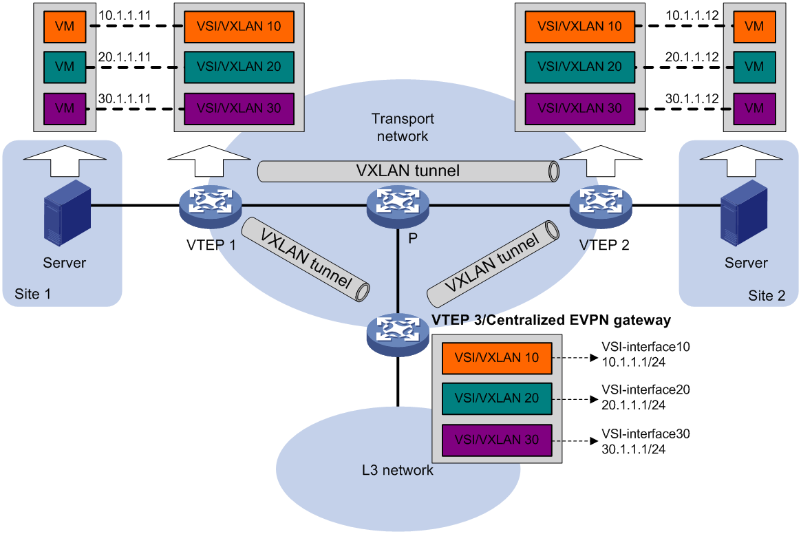
As shown in Figure 7, a VTEP acts as a gateway for VMs in the VXLANs. The VTEP both terminates the VXLANs and performs Layer 3 forwarding for the VMs. The network uses the following process to forward Layer 3 traffic from a VM to the destination:
1. The VM sends an ARP request to obtain the MAC address of the VSI interface that acts as the gateway, and then sends the Layer 3 traffic to the centralized EVPN gateway.
2. The local VTEP looks up the matching VSI's MAC address table and forwards the traffic to the centralized EVPN gateway through a VXLAN tunnel.
3. The centralized EVPN gateway removes the VXLAN encapsulation and forwards the traffic at Layer 3.
4. The centralized EVPN gateway forwards the replies sent by the destination node to the VM based on the ARP entry for the VM.
Figure 7 Example of centralized EVPN gateway deployment
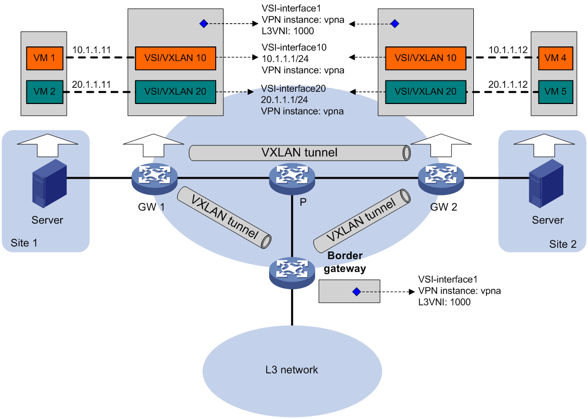
Distributed EVPN gateway deployment
About distributed EVPN gateway deployment
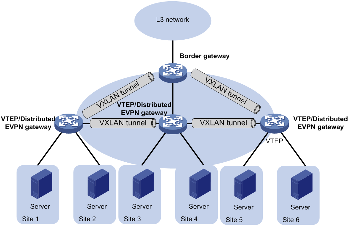
As shown in Figure 8, each site's VTEP acts as a gateway to perform Layer 3 forwarding for the VXLANs of the local site. A VTEP acts as a border gateway to the Layer 3 network for the VXLANs.
Figure 8 Distributed EVPN gateway placement design
Symmetric IRB
A distributed EVPN gateway uses symmetric IRB for Layer 3 forwarding, which means both the ingress and egress gateways perform Layer 2 and Layer 3 lookups. Symmetric IRB introduces the following concepts:
· L3 VXLAN ID—Also called L3 VNI. An L3 VXLAN ID identifies the traffic of a routing domain where devices have Layer 3 reachability. An L3 VXLAN ID is associated with one VPN instance. Distributed EVPN gateways use VPN instances to isolate traffic of different services on VXLAN tunnel interfaces.
· Router MAC address—Each distributed EVPN gateway has a unique router MAC address used for inter-gateway forwarding. The MAC addresses in the inner Ethernet header of VXLAN packets are router MAC addresses of distributed EVPN gateways.
VSI interfaces
As shown in Figure 9, each distributed EVPN gateway has the following types of VSI interfaces:
· VSI interface as a gateway interface of a VXLAN—The VSI interface acts as the gateway interface for VMs in a VXLAN. The VSI interface is associated with a VSI and a VPN instance. On different distributed EVPN gateways, the VSI interface of a VXLAN use the same IP address to provide services.
· VSI interface associated with an L3 VXLAN ID—The VSI interface is associated with a VPN instance and assigned an L3 VXLAN ID. VSI interfaces associated with the same VPN instance share an L3 VXLAN ID.
A border gateway only has VSI interfaces that are associated with an L3 VXLAN ID.
Figure 9 Example of distributed EVPN gateway deployment
Layer 3 forwarding entry learning
A distributed EVPN gateway forwards Layer 3 traffic based on FIB entries generated from BGP EVPN routes and ARP information.
A VTEP advertises an external route imported in the EVPN address family through MP-BGP. A remote VTEP adds the route to the FIB table of a VPN instance based on the L3 VXLAN ID carried in the route. In the FIB entry, the outgoing interface is a VXLAN tunnel interface, and the next hop is the peer VTEP address in the NEXT_HOP attribute of the route.
A VTEP has the following types of ARP information:
· Local ARP information—ARP information of VMs in the local site. The VTEP snoops GARP packets, RARP packets, and ARP requests for the gateway MAC address to learn the ARP information of the senders and generates ARP entries and FIB entries. In an ARP or FIB entry, the outgoing interface is the site-facing interface where the packet is received, and the VPN instance is the instance associated with the corresponding VSI interface.
· Remote ARP information—ARP information of VMs in remote sites. Each VTEP uses MP-BGP to advertise its local ARP information with L3 VXLAN IDs in routes to remote sites. A VTEP generates only FIB entries for the remote ARP information. A FIB entry contains the following information:
¡ Outgoing interface: VSI interface associated with the L3 VXLAN ID.
¡ Next hop: Peer VTEP address in the NEXT_HOP attribute of the route.
¡ VPN instance: VPN instance associated with the L3 VXLAN ID.
The VTEP then creates an ARP entry for the next hop in the FIB entry.
Traffic forwarding
A distributed EVPN gateway can work in one of the following mode:
· Switching and routing mode—Forwards Layer 2 traffic based on the MAC address table and forwards Layer 3 traffic based on the FIB table. In this mode, you need to enable ARP flood suppression on the distributed EVPN gateway to reduce flooding.
· Routing mode— Forwards both Layer 2 and Layer 3 traffic based on the FIB table. In this mode, you need to enable local proxy ARP on the distributed EVPN gateway.
For more information about MAC address table-based Layer 2 forwarding, see "Unicast."
Figure 10 shows the intra-site Layer 3 forwarding process.
1. The source VM sends an ARP request to obtain the MAC address of the destination VM.
2. The gateway replies to the source VM with the MAC address of the VSI interface associated with the source VM's VSI.
3. The source VM sends a Layer 3 packet to the gateway.
4. The gateway looks up the FIB table of the VPN instance associated with the source VM's VSI and finds the matching outgoing site-facing interface.
5. The gateway processes the Ethernet header of the Layer 3 packet as follows:
¡ Replaces the destination MAC address with the destination VM's MAC address.
¡ Replaces the source MAC address with the VSI interface's MAC address.
6. The gateway forwards the Layer 3 packet to the destination VM.
Figure 10 Intra-site Layer 3 forwarding
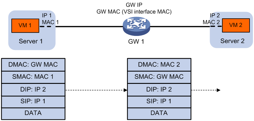
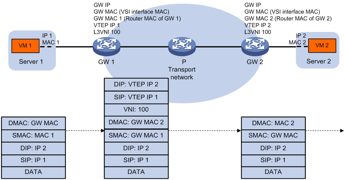
Figure 11 shows the inter-site Layer 3 forwarding process.
1. The source VM sends an ARP request to obtain the MAC address of the destination VM.
2. The gateway replies to the source VM with the MAC address of the VSI interface associated with the source VM's VSI.
3. The source VM sends a Layer 3 packet to the gateway.
4. The gateway looks up the FIB table of the VPN instance associated with the source VM's VSI and finds the matching outgoing VSI interface.
5. The gateway processes the Ethernet header of the Layer 3 packet as follows:
¡ Replaces the destination MAC address with the destination gateway's router MAC address.
¡ Replaces the source MAC address with its own router MAC address.
6. The gateway adds VXLAN encapsulation to the Layer 3 packet and forwards the packet to the destination gateway. The encapsulated VXLAN ID is the L3 VXLAN ID of the corresponding VPN instance.
7. The destination gateway identifies the VPN instance of the packet based on the L3 VXLAN ID and removes the VXLAN encapsulation. Then the gateway forwards the packet based on the matching ARP entry.
Figure 11 Inter-site Layer 3 forwarding
Communication between private and public networks
A distributed EVPN gateway uses the public instance to perform Layer 3 forwarding for the public network and to enable communication between private and public networks. The public instance is similar to a VPN instance. A distributed EVPN gateway processes traffic of the public instance in the same way it does for a VPN instance. For the public instance to work correctly, you must configure an RD, an L3 VXLAN ID, and route targets for it. If a VSI interface is not associated with any VPN instance, the VSI interface belongs to the public instance.
RD and route target selection of BGP EVPN routes
As shown in Table 1, you can configure RDs and route targets for BGP EVPN routes in multiple views.
Table 1 Supported views for RD and route target configuration
|
Item |
Views |
|
RD |
· VSI EVPN instance view · VPN instance view · Public instance view |
|
Route targets |
· VSI EVPN instance view · VPN instance view · VPN instance IPv4 address family view · VPN instance IPv6 address family view · VPN instance EVPN view · Public instance view · Public instance IPv4 address family view · Public instance IPv6 address family view · Public instance EVPN view NOTE: Route targets configured in VPN instance view apply to IPv4 VPN, IPv6 VPN, and EVPN. Route targets configured in IPv4 address family view apply only to IPv4 VPN. Route targets configured in IPv6 address family view apply only to IPv6 VPN. Route targets configured in VPN instance EVPN view apply only to EVPN. Route targets configured in IPv4 address family view, IPv6 address family view, or VPN instance EVPN view take precedence over those in VPN instance view. The precedence order for different views of a VPN instance also applies to the views of the public instance. |
The device selects RDs and route targets for BGP EVPN routes by using the following rules:
· IMET routes and MAC/IP advertisement routes that contain only MAC addresses—The device uses the RD and route targets configured in EVPN instance view when advertising and accepting the routes.
· MAC/IP advertisement routes that contain ARP or ND information—The device uses the following settings when advertising the routes:
¡ RD and export route targets configured in EVPN instance view.
¡ Export route targets configured for EVPN on a VPN instance or the public instance (VPN instance view, EVPN view of a VPN instance or the public instance, and public instance view).
The device uses the import route targets configured for EVPN on a VPN instance or the public instance when accepting the routes.
· IP prefix advertisement routes—The device uses the route targets configured for the IPv4 or IPv6 address family on a VPN instance or the public instance when advertising and accepting the routes.
EVPN multihoming
About EVPN multihoming
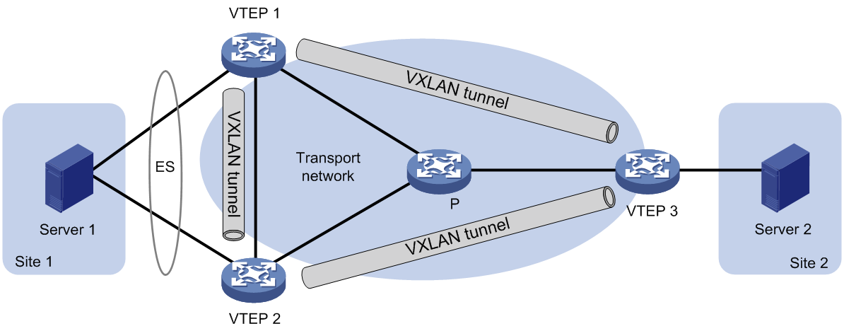
As shown in Figure 12, EVPN supports deploying multiple VTEPs at a site for redundancy and high availability. On the redundant VTEPs, Ethernet links connected to the site form an Ethernet segment (ES) that is uniquely identified by an Ethernet segment identifier (ESI).
Hardware compatibility with EVPN multihoming
EVPN multihoming is not supported by the following switches:
· S6820 switch series.
· S6800 switches labeled with the following product codes:
¡ LS-6800-2C.
¡ LS-6800-32Q.
¡ LS-6800-4C.
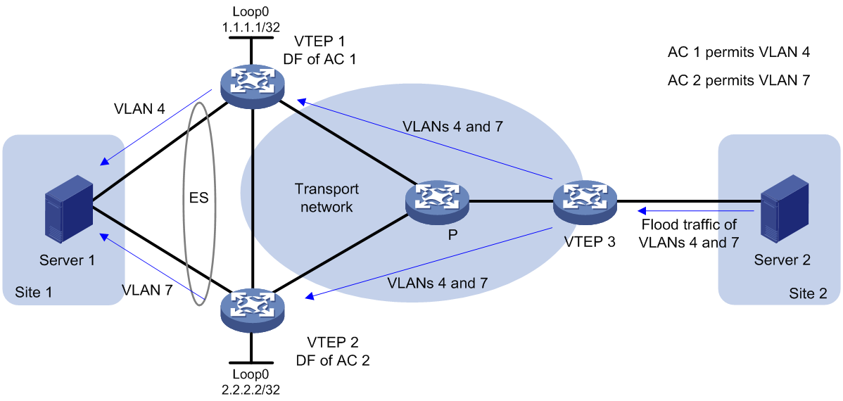
DF election
To prevent redundant VTEPs from sending duplicate flood traffic to a multihomed site, a designated forwarder (DF) is elected from the VTEPs for each AC to forward flood traffic to the AC. VTEPs that fail the election are assigned the backup designated forwarder (BDF) role. BDFs of an AC do not forward flood traffic to the AC.
A remote VTEP takes part in the DF election of a multihomed site. Redundant VTEPs of the site send Ethernet segment routes to the remote VTEP to advertise ES and VTEP IP mappings. Then, the VTEPs select a DF for each AC based on the ES and VTEP IP mappings by using the following procedure:
2. Divide the lowest VLAN ID permitted on an AC by the number of the redundant VTEPs, and match the reminder to the sequence numbers of IP addresses.
3. Assign the DF role to the VTEP that uses the IP address with the matching sequence number.
The following uses AC 1 in Figure 13 as an example to explain the DF election procedure:
1. VTEP 1 and VTEP 2 send Ethernet segment routes to VTEP 3.
2. Sequence numbers 0 and 1 are assigned to IP addresses 1.1.1.1 and 2.2.2.2 in the Ethernet segment routes, respectively.
3. The VTEPs divide 4 (the lowest VLAN ID permitted by AC 1) by 2 (the number of redundant VTEPs), and match the reminder 0 to the sequence numbers of the IP addresses.
4. The DF role is assigned to VTEP 1 at 1.1.1.1.
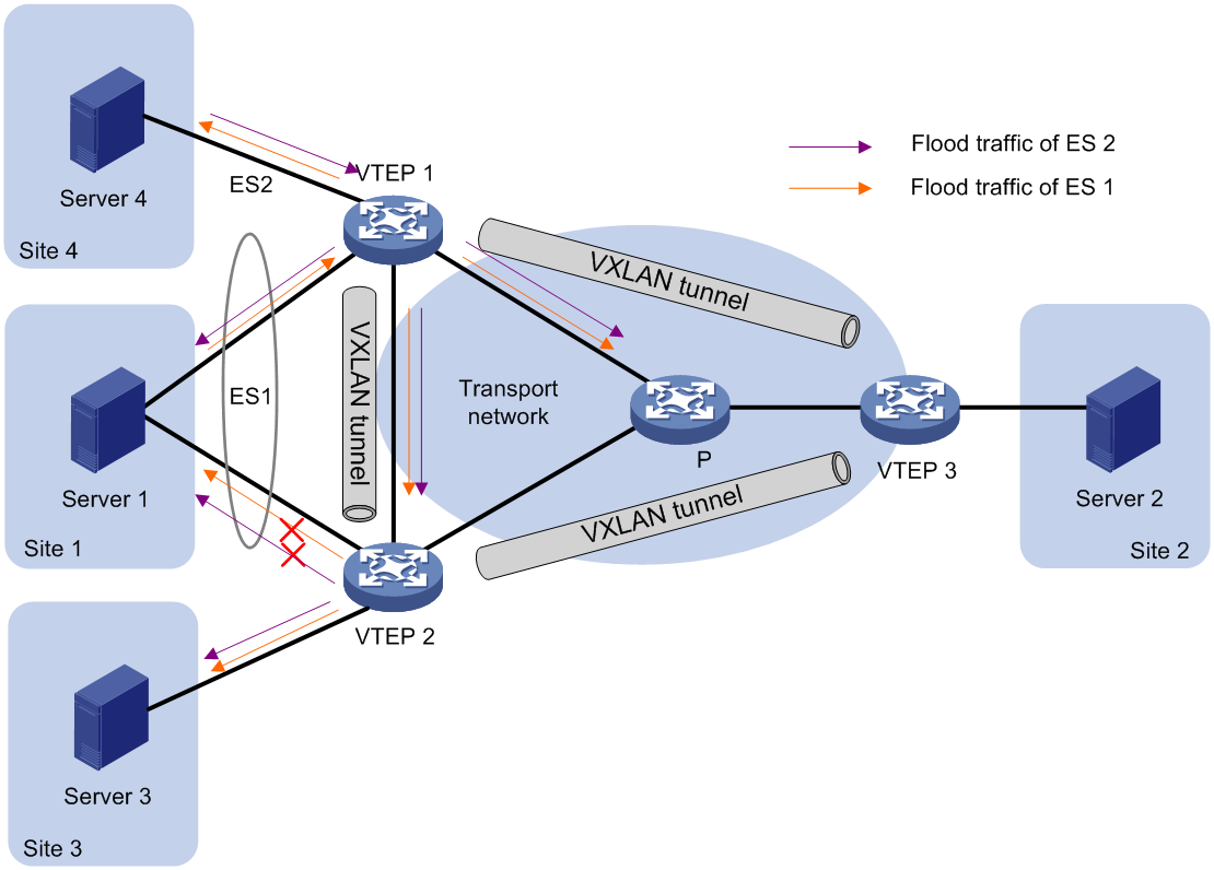
Split horizon
In a multihomed site, a VTEP forwards multicast, broadcast, and unknown unicast frames received from ACs out of all site-facing interfaces and VXLAN tunnels in the corresponding VXLAN, except for the incoming interface. As a result, the other VTEPs at the site receive these flood frames and forward them to site-facing interfaces, which causes duplicate floods and loops. EVPN introduces split horizon to resolve this issue. Split horizon disables a VTEP from forwarding flood traffic received from another local VTEP to site-facing interfaces if an ES on that local VTEP has the same ESI as these interfaces. As shown in Figure 14, both VTEP 1 and VTEP 2 have ES 1. When receiving flood traffic from VTEP 1, VTEP 2 does not forward the traffic to interfaces with ESI 1.
Redundancy mode
The device supports the all-active redundancy mode of EVPN multihoming. This mode allows all redundant VTEPs at a multihomed site to forward broadcast, multicast, and unknown unicast traffic.
· For flood frames received from remotes sites, a VTEP forwards them to the ACs of which it is the DF.
· For flood frames received from the local site, a VTEP forwards them out of all site-facing interfaces and VXLAN tunnels in the corresponding VXLAN, except for the incoming interfaces. For flood frames to be sent out of a VXLAN tunnel interface, a VTEP replicates each flood frame and sends one replica to all the other VTEPs in the corresponding VXLAN.
IP aliasing
In all-active redundancy mode, all redundant VTEPs of an ES advertise the ES to remote VTEPs through MP-BGP. IP aliasing allows a remote VTEP to add the IP addresses of all the redundant VTEPs as the next hops for the MAC or ARP information received from one of these VTEPs. This mechanism creates ECMP routes between the remote VTEP and the redundant VTEPs.
EVPN multicast
EVPN supports multicast forwarding. In an EVPN network, VTEPs create and maintain multicast forwarding entries based on received IGMP membership reports and leave group messages to reduce IGMP floods.
Hardware compatibility with EVPN multicast
EVPN multicast is not supported by the following switches:
· S6820 switch series.
· S6800 switches labeled with the following product codes:
¡ LS-6800-2C.
¡ LS-6800-32Q.
¡ LS-6800-4C.
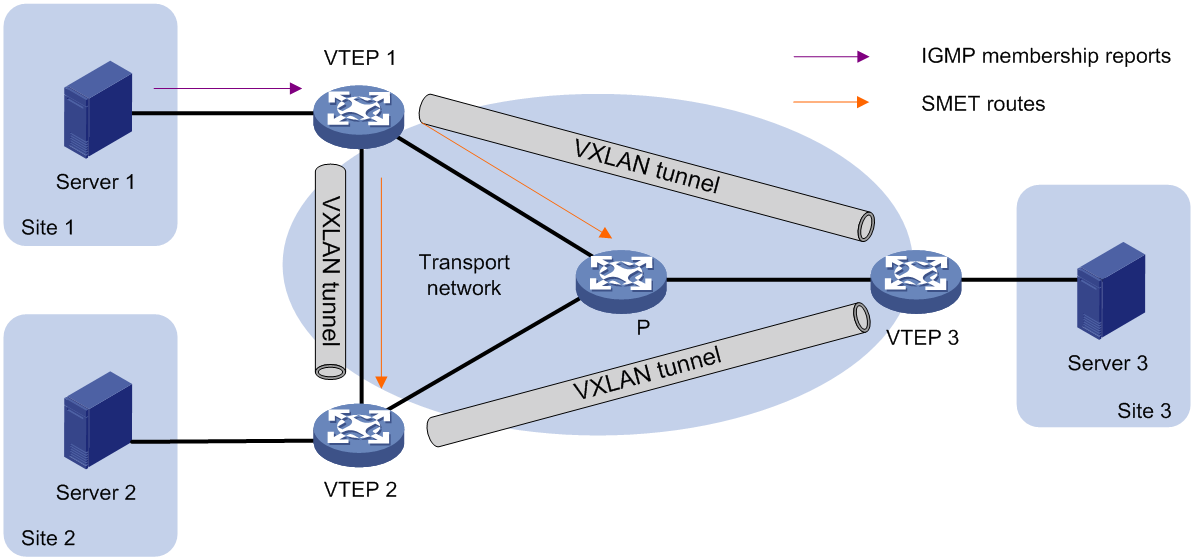
Multicast in single-homed sites
As shown in Figure 15, VTEPs at single-homed sites create multicast forwarding entries by using the following procedure:
1. VTEP 1 receives the IGMP membership report sent by Server 1.
2. VTEP 1 creates a multicast forwarding entry and advertises information about the multicast group to VTEP 2 and VTEP 3 through an SMET route.
3. VTEP 2 and VTEP 3 create multicast forwarding entries based on the SMET route. The next hop in the entries is VTEP 1.
Figure 15 Multicast in single-homed sites
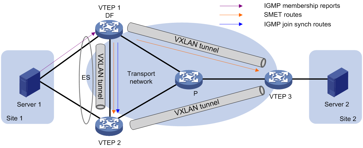
Multicast in multihomed sites
The IGMP membership reports and leave group messages sent from a multihomed site are received by multiple VTEPs. To ensure consistency of multicast forwarding entries, redundant VTEPs advertise IGMP join synch and leave synch routes to synchronize multicast information for each ES.
As shown in Figure 16, if the DF receives the first membership report for an IGMP multicast group, the following route advertisement and withdrawal process takes place:
1. VTEP 1 (DF) receives an IGMP membership report.
2. VTEP 1 sends an SMET route to VTEP 2 and VTEP 3, and sends an IGMP join synch route to VTEP 2.
3. An IGMP leave group message is sent from Site 1, and one of the following processes occurs:
¡ If VTEP 1 (DF) receives the message, it sends an IGMP leave synch route to VTEP 2 and withdraws the SMET route and IGMP join synch route that it has advertised.
¡ If VTEP 2 (BDF) receives the message, it sends an IGMP leave synch route to VTEP 1. Then VTEP 1 withdraws the SMET route and IGMP join synch route that it has advertised.
As shown in Figure 16, if the BDF receives the first membership report for an IGMP multicast group, the following route advertisement and withdrawal process takes place:
4. VTEP 2 (BDF) receives an IGMP membership report.
5. VTEP 2 sends an IGMP join synch route to VTEP 1 (DF).
6. VTEP 1 sends an SMET route to VTEP 2 and VTEP 3.
7. An IGMP leave group message is sent from Site 1, and one of the following processes occurs:
¡ If VTEP 1 (DF) receives the message, it sends an IGMP leave synch route to VTEP 2, and VTEP 2 withdraws the IGMP join synch route that it has advertised. Then, VTEP 1 withdraws the SMET route that it has advertised.
¡ If VTEP 2 (BDF) receives the message, it sends an IGMP leave synch route to VTEP 1 and withdraws the IGMP join synch route that it has advertised. Then, VTEP 1 withdraws the SMET route that it has advertised.
Figure 16 Multicast in multihomed sites
ARP and ND flood suppression
ARP or ND flood suppression reduces ARP request broadcasts or ND request multicasts by enabling the VTEP to reply to ARP or ND requests on behalf of VMs.
As shown in Figure 17, this feature snoops ARP or ND requests, ARP or ND responses, and BGP EVPN routes to populate the ARP or ND flood suppression table with local and remote MAC addresses. If an ARP or ND request has a matching entry, the VTEP replies to the request on behalf of the VM. If no match is found, the VTEP floods the request to both local and remote sites.
Figure 17 ARP and ND flood suppression
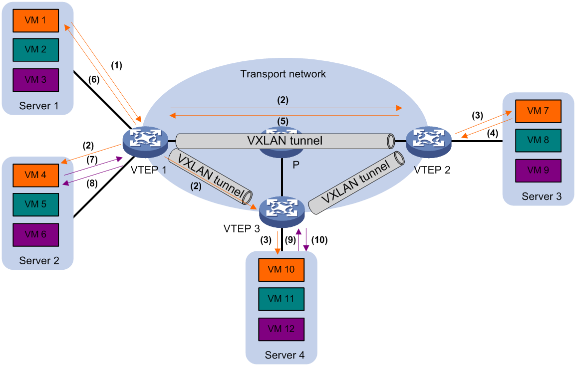
The following uses ARP flood suppression as an example to explain the flood suppression workflow:
1. VM 1 sends an ARP request to obtain the MAC address of VM 7.
2. VTEP 1 creates a suppression entry for VM 1, floods the ARP request in the VXLAN, and sends the suppression entry to VTEP 2 and VTEP 3 through BGP EVPN.
3. VTEP 2 and VTEP 3 de-encapsulate the ARP request and broadcast the request in the local site.
4. VM 7 sends an ARP reply.
5. VTEP 2 creates a suppression entry for VM 7, forwards the ARP reply to VTEP 1, and sends the suppression entry to VTEP 1 and VTEP 3 through BGP EVPN.
6. VTEP 1 de-encapsulates the ARP reply and forwards the ARP reply to VM 1.
7. VM 4 sends an ARP request to obtain the MAC address of VM 1.
8. VTEP 1 creates a suppression entry for VM 4 and replies to the ARP request.
9. VM 10 sends an ARP request to obtain the MAC address of VM 1.
10. VTEP 3 creates a suppression entry for VM 10 and replies to the ARP request.
MAC mobility
MAC mobility refers to that a VM or host moves from one ES to another. The source VTEP is unaware of the MAC move event. To notify other VTEPs of the change, the destination VTEP advertises a MAC/IP advertisement route for the MAC address. The source VTEP withdraws the old route for the MAC address after receiving the new route. The MAC/IP advertisement route has a sequence number that increases when the MAC address moves. The sequence number identifies the most recent move if the MAC address moves multiple times.
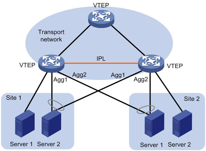
EVPN distributed relay
|
|
NOTE: EVPN distributed relay supports only IPv4 sites. |
As shown in Figure 18, EVPN distributed relay virtualizes two VTEPs or EVPN gateways into one distributed-relay (DR) system through Distributed Resilient Network Interconnect (DRNI) to avoid single points of failure. The VTEPs or EVPN gateways are called DR member devices. For more information about DRNI, see Layer 2—LAN Switching Configuration Guide.
EVPN distributed relay uses the following mechanisms:
· VM reachability information synchronization—To ensure VM reachability information consistency in the DR system, the DR member devices synchronize MAC address entries and ARP information with each other through an intra-portal link (IPL). The IPL can be an Ethernet aggregate link or a VXLAN tunnel.
|
IMPORTANT: The VXLAN tunnel that acts as the IPL is automatically associated with all VXLANs on each DR member device. |
· Virtual VTEP address—The DR member devices use a virtual VTEP address to set up VXLAN tunnels with remote VTEPs or EVPN gateways.
· Independent BGP neighbor relationship establishment—The DR member devices use different BGP peer addresses to establish neighbor relationships with remote devices. For load sharing and link redundancy, a neighbor sends traffic destined for the virtual VTEP address to both of the DR member devices through ECMP routes of the underlay network.
· Site-facing link redundancy—As shown in Figure 18, a VM accesses the EVPN network through multiple Ethernet links that connect to the VTEPs. On each VTEP, all site-facing Ethernet links are assigned to a Layer 2 aggregation group for high availability. On the corresponding Layer 2 aggregate interfaces, Ethernet service instances are configured as ACs of VXLANs to match customer traffic.
¡ If you specify the Ethernet aggregate link between the VTEPs as the IPL, the site-facing link backup mechanism is as follows:
When a site-facing AC is configured on a DR member device, the device automatically creates an AC on the IPL with the same traffic match criterion as the site-facing AC. Then, it maps the automatically created AC to the VSI of the site-facing AC. When the site-facing AC is down, traffic sent to the AC is forwarded to the other DR member device through the IPL. This mechanism ensures service continuity in case of AC failure.
¡ If a VXLAN tunnel acts as the IPL, the site-facing link backup mechanism is as follows:
If a site-facing AC on a DR member device is down, traffic sent to the AC will be encapsulated into VXLAN packets. The VXLAN ID belongs to the VXLAN that is associated with the VSI of the site-facing AC. The DR member device forwards the VXLAN packets through the IPL VXLAN tunnel to the peer DR member device. The peer DR member device assigns the traffic to the correct VSI based on the VXLAN ID in the received packets.
¡ If you specify the Ethernet aggregate link between the VTEPs as the IPL, the traffic forwarding mechanism is as follows:
When a single-armed AC is configured on a VTEP, the VTEP automatically creates an AC on the IPL with the same traffic match criterion as the single-armed AC. Then, it maps the automatically created AC to the VSI of the single-armed AC. When receiving traffic from the single-armed AC, the VTEP sends the traffic to the other VTEP through the IPL. Then the other VTEP identifies the VSI of the traffic and forwards it.
¡ If a VXLAN tunnel acts as the IPL, the traffic forwarding mechanism is as follows:
When receiving traffic from a single-armed AC, a VTEP encapsulates the traffic into VXLAN packets and sends them to the other VTEP through the IPL. The VXLAN ID in the VXLAN packets belongs to the VSI to which the single-armed AC is mapped. Then the other VTEP identifies the VSI of the traffic and forwards it.
Figure 18 EVPN distributed relay
Configuring EVPN
Restrictions: Hardware compatibility with EVPN gateways
EVPN gateways are not supported by S6800 switches labeled with the following product codes:
· LS-6800-2C.
· LS-6800-32Q.
· LS-6800-4C.
Restrictions and guidelines: EVPN configuration
Make sure the following VXLAN tunnels are not associated with the same VXLAN when they have the same tunnel destination IP address:
· A VXLAN tunnel automatically created by EVPN.
· A manually created VXLAN tunnel.
For more information about manual tunnel configuration, see VXLAN Configuration Guide.
As a best practice to ensure correct traffic forwarding, configure the same MAC address for all VSI interfaces on an EVPN gateway.
When you configure EVPN gateways, follow these restrictions and guidelines:
|
Device role |
Configuration |
Restrictions and guidelines |
|
EVPN gateway |
Ethernet service instance and access mode |
· Use the Ethernet access mode if an Ethernet service instance uses the encapsulation untagged criterion. · Use the VLAN access mode if an Ethernet service instance uses the encapsulation s-vid { vlan-id [ only-tagged ] | vlan-id-list } criterion. |
|
Priority trust mode |
An EVPN gateway processes the DSCP precedence in frames received from an AC as follows: · For Layer 3 forwarding, the gateway always uses the DSCP precedence for priority mapping, regardless of whether you configure the qos trust dscp command on the incoming interface. · For Layer 2 forwarding, the gateway uses the DSCP precedence for priority mapping only when the qos trust dscp command is configured on the incoming interface. |
|
|
PBR |
A PBR policy cannot match VXLAN packets by the source and destination IP addresses in the outer IP header on a Layer 3 interface (VSI interfaces not included). To match VXLAN packets by the source and destination IP addresses in the outer IP header, apply a PBR policy to a VSI interface. |
|
|
VTEP |
PBR |
On a Layer 3 interface, a PBR policy cannot match VXLAN packets by the source and destination IP addresses in the outer IP header. |
|
Border gateway (S6800 and S6860 switch series) |
ACL |
An ACL applied to a Layer 3 Ethernet interface or Layer 3 aggregate interface matches packets on both the interface and its subinterfaces. For more information about ACLs, see ACL and QoS Configuration Guide. |
|
QoS |
· A QoS policy applied to a Layer 3 Ethernet interface also takes effect on its subinterfaces if the QoS policy does not contain inner and outer VLAN ID match criteria. For more information about QoS policies, see ACL and QoS Configuration Guide. · If a QoS policy is applied to an interface other than a Layer 3 Ethernet interface, the inner and outer VLAN ID match criteria in the QoS policy cannot match untagged packets that are forwarded at Layer 3. |
|
|
PBR |
A PBR policy applied to a Layer 3 Ethernet interface or Layer 3 aggregate interface takes effect on both the interface and its subinterfaces. For more information about PBR, see Layer 3—IP Routing Configuration Guide. |
|
|
Storm suppression |
Broadcast, multicast, or unknown unicast storm suppression configured on a Layer 3 Ethernet interface takes effect on both the interface and its subinterfaces. For more information about storm suppression, see Layer 2—LAN Switching Configuration Guide. |
|
|
MAC address assignment |
Do not use the mac-address command to assign MAC addresses to the following interfaces: · Layer 3 Ethernet interfaces. · Layer 3 Ethernet subinterfaces. · Layer 3 aggregate interfaces. · Layer 3 aggregate subinterfaces. |
|
|
ARP |
You cannot execute the arp mode uni command on interfaces of a Layer 3 border gateway. For more information about this command, see ARP commands in Layer 3—IP Services Command Reference. |
EVPN tasks at a glance
To configure EVPN, perform the following tasks:
1. Setting the VXLAN hardware resource mode
2. Configuring a VXLAN on a VSI
b. (Optional.) Configuring VSI parameters
3. Configuring an EVPN instance
4. (Optional.) Configuring EVPN multihoming
a. Assigning an ESI to an interface
b. (Optional.) Setting the DF election delay
c. Disabling advertisement of EVPN multihoming routes
5. Configuring BGP to advertise BGP EVPN routes
a. Enabling BGP to advertise BGP EVPN routes
b. (Optional.) Configuring optimal route selection and route advertisement settings
c. (Optional.) Maintaining BGP sessions
7. Configuring an EVPN gateway
Choose one of the following tasks:
¡ Configuring a centralized EVPN gateway
¡ Configuring a distributed EVPN gateway
8. (Optional.) Managing remote MAC address entries and remote ARP or ND learning
¡ Disabling remote MAC address learning and remote ARP or ND learning
¡ Disabling MAC address advertisement
¡ Disabling learning of MAC addresses from ARP or ND information
¡ Disabling ARP information advertisement
¡ Enabling ARP mobility event suppression
9. (Optional.) Enabling conversational learning for forwarding entries
To save device hardware resources, remote MAC entries and host route FIB entries are issued to the hardware only when the entries are required for packet forwarding.
¡ Enabling conversational learning for remote MAC address entries
¡ Enabling conversational learning for host route FIB entries
10. (Optional.) Configuring BGP EVPN route redistribution and advertisement
¡ Redistributing MAC/IP advertisement routes into BGP unicast routing tables
¡ Enabling BGP EVPN route advertisement to the local site
11. (Optional.) Maintaining and optimizing an EVPN network
¡ Disabling flooding for a VSI
¡ Enabling ARP or ND flood suppression
¡ Enabling packet statistics for VXLAN tunnels
12. (Optional.) Configuring EVPN distributed relay
Perform this task to virtualize two VTEPs or EVPN gateways into one DR system to avoid single points of failure.
Setting the VXLAN hardware resource mode
Setting the VXLAN hardware resource mode (S6800 and S6860 switch series)
About the VXLAN hardware resource mode
Set the hardware resource mode for VXLAN based on the role of the device.
· l2gw—Applies to VTEPs that perform only Layer 2 forwarding.
· l3gw8k, l3gw16k, l3gw24k, l3gw32k, or l3gw40k—Applies to VXLAN IP gateways.
· border8k, border16k, border24k, border28k, border32k, or border40k—Applies to Layer 3 border gateways that provide access to external networks.
Hardware and feature compatibility
This feature is not supported by S6800 switches labeled with the following product codes:
· LS-6800-2C.
· LS-6800-32Q.
· LS-6800-4C.
Restrictions and guidelines
For the hardware resource mode to take effect, you must reboot the device.
Procedure
1. Enter system view.
system-view
2. Set the VXLAN hardware resource mode.
hardware-resource vxlan { border8k | border16k | border24k | border28k | border32k | border40k | l2gw | l3gw8k | l3gw16k | l3gw24k | l3gw32k | l3gw40k }
By default, the VXLAN hardware resource mode is l2gw.
For more information about this command, see VXLAN Command Reference.
The S6800 switch series does not support the border28k keyword.
The S6860 switch series does not support the border8k, border16k, border32k, border40k, l3gw32k, or l3gw40k keyword.
Setting the VXLAN hardware resource mode (S6820 switch series)
About the VXLAN hardware resource mode
The device supports the following VXLAN hardware resource modes:
· l3gw—Layer 3 gateway mode. In this mode, VXLAN-DCI is not supported, and you can create more ACs and VXLAN tunnels than in border mode.
· border—Border mode. In this mode, VXLAN-DCI is supported, and you can create less ACs and VXLAN tunnels than in Layer 3 gateway mode.
You must set the VXLAN hardware resource mode to border on EDs of a VXLAN-DCI network.
Restrictions and guidelines
For the hardware resource mode to take effect, you must reboot the device.
Procedure
1. Enter system view.
system-view
2. Set the VXLAN hardware resource mode.
hardware-resource vxlan { l3gw | border }
By default, the VXLAN hardware resource mode is l3gw.
For more information about this command, see VXLAN Command Reference.
Configuring a VXLAN on a VSI
Restrictions and guidelines for VXLAN configuration on a VSI
For more information about the VXLAN commands in this task, see VXLAN Command Reference.
Creating a VXLAN on a VSI
1. Enter system view.
system-view
2. Enable L2VPN.
l2vpn enable
By default, L2VPN is disabled.
3. Create a VSI and enter VSI view.
vsi vsi-name
4. Enable the VSI.
undo shutdown
By default, a VSI is enabled.
5. Create a VXLAN and enter VXLAN view.
vxlan vxlan-id
You can create only one VXLAN on a VSI. The VXLAN ID must be unique for each VSI.
Configuring VSI parameters
1. Enter system view.
system-view
2. Enter VSI view.
vsi vsi-name
3. Configure a VSI description.
description text
By default, a VSI does not have a description.
4. Set the MTU for the VSI.
mtu size
The default MTU is 1500 bytes for a VSI.
5. Set the maximum bandwidth for known unicast traffic of the VSI.
bandwidth bandwidth
By default, the maximum bandwidth is not limited for known unicast traffic of a VSI.
6. Set the broadcast, multicast, or unknown unicast restraint bandwidth for the VSI.
restrain { broadcast | multicast | unknown-unicast } bandwidth
By default, a VSI's broadcast restraint bandwidth, multicast restraint bandwidth, and unknown unicast restraint bandwidth are not set.
7. Enable MAC address learning for the VSI.
mac-learning enable
By default, MAC address learning is enabled for a VSI.
Configuring an EVPN instance
About EVPN instances
You do not need to associate a VPN instance with a VXLAN that requires only Layer 2 connectivity. The BGP EVPN routes advertised by the device carry the RD and route targets configured for the EVPN instance associated with the VXLAN.
Procedure
1. Enter system view.
system-view
2. Enter VSI view.
vsi vsi-name
3. Create an EVPN instance and enter EVPN instance view.
evpn encapsulation vxlan
4. Configure an RD for the EVPN instance.
route-distinguisher { route-distinguisher | auto [ router-id ] }
By default, no RD is configured for an EVPN instance.
5. Configure route targets for the EVPN instance.
vpn-target { vpn-target&<1-8> | auto } [ both | export-extcommunity | import-extcommunity ]
By default, an EVPN instance does not have route targets.
Make sure the following requirements are met:
¡ The import targets of the EVPN instance do not match the export targets of the VPN instance associated with the VXLAN or the public instance.
¡ The export targets of the EVPN instance do not match the import targets of the VPN instance associated with the VXLAN or the public instance.
For more information about VPN instance configuration and public instance configuration, see "Configuring an L3 VXLAN ID for a VSI interface."
Configuring EVPN multihoming
Restrictions and guidelines for EVPN multihoming
In a multihomed site, AC configuration and VXLAN IDs must be consistent on redundant VTEPs of the same ES. For each VXLAN ID, you must configure unique RDs for the EVPN instance of VSIs on the redundant VTEPs. You must configure different RDs for the VPN instances and the public instance that use the same VXLAN IP gateway.
Hardware compatibility with EVPN multihoming
EVPN multihoming is not supported by the following switches:
· S6820 switch series.
· S6800 switches labeled with the following product codes:
¡ LS-6800-2C.
¡ LS-6800-32Q.
¡ LS-6800-4C.
Assigning an ESI to an interface
About ESIs
An ESI uniquely identifies an ES. The links on interfaces with the same ESI belong to the same ES. Traffic of the ES can be distributed among the links for load sharing.
Procedure
1. Enter system view.
system-view
2. Enter interface view.
¡ Enter Layer 2 Ethernet interface view.
interface interface-type interface-number
¡ Enter Layer 2 aggregate interface view.
interface bridge-aggregation interface-number
3. Assign an ESI to the interface.
esi esi-id
By default, no ESI is assigned to an interface.
Setting the DF election delay
About the DF election delay
The DF election can be triggered by site-facing interface status changes, redundant VTEP membership changes, and interface ESI changes. To prevent frequent DF elections from degrading network performance, set the DF election delay. The DF election delay defines the minimum interval allowed between two DF elections.
Procedure
1. Enter system view.
system-view
2. Set the DF election delay.
evpn multihoming timer df-delay delay-value
By default, the DF election delay is 3 seconds.
Disabling advertisement of EVPN multihoming routes
About advertisement of EVPN multihoming routes
EVPN multihoming routes include Ethernet auto-discovery routes and Ethernet segment routes.
In a multihomed EVPN network, perform this task on a redundant VTEP before you reboot it. This operation allows other VTEPs to refresh their EVPN routing table to prevent traffic interruption caused by the reboot.
Procedure
1. Enter system view.
system-view
2. Disable advertisement of EVPN multihoming routes and withdraw the EVPN multihoming routes that have been advertised to remote sites.
evpn multihoming advertise disable
By default, the device advertises EVPN multihoming routes.
Configuring BGP to advertise BGP EVPN routes
Restrictions and guidelines for BGP EVPN route advertisement
For more information about BGP commands in this task, see Layer 3—IP Routing Command Reference.
Enabling BGP to advertise BGP EVPN routes
1. Enter system view.
system-view
2. Configure a global router ID.
router id router-id
By default, no global router ID is configured.
3. Enable a BGP instance and enter BGP instance view.
bgp as-number [ instance instance-name ]
By default, BGP is disabled and no BGP instances exist.
4. Specify remote VTEPs as BGP peers.
peer { group-name | ipv4-address [ mask-length ] } as-number as-number
5. Create the BGP EVPN address family and enter BGP EVPN address family view.
address-family l2vpn evpn
6. Enable BGP to exchange BGP EVPN routes with a peer or peer group.
peer { group-name | ipv4-address [ mask-length ] } enable
By default, BGP does not exchange BGP EVPN routes with peers.
Configuring optimal route selection and route advertisement settings
1. Enter system view.
system-view
2. Enter BGP instance view.
bgp as-number [ instance instance-name ]
3. Enter BGP EVPN address family view.
address-family l2vpn evpn
4. Permit the local AS number to appear in routes from a peer or peer group and set the number of appearances.
peer { group-name | ipv4-address [ mask-length ] } allow-as-loop [ number ]
By default, the local AS number is not allowed in routes from peers.
5. Enable route target filtering for BGP EVPN routes.
policy vpn-target
By default, route target filtering is enabled for BGP EVPN routes.
6. (Optional.) Set the optimal route selection delay timer.
route-select delay delay-value
By default, the optimal route selection delay timer is 0 seconds, which means optimal route selection is not delayed.
7. Configure BGP route reflection settings:
a. Configure the device as an RR and specify a peer or peer group as its client.
peer { group-name | ipv4-address [ mask-length ] } reflect-client
By default, no RR or client is configured.
b. (Optional.) Enable BGP EVPN route reflection between clients.
reflect between-clients
By default, BGP EVPN route reflection between clients is enabled.
c. (Optional.) Configure the cluster ID of the RR.
reflector cluster-id { cluster-id | ipv4-address }
By default, an RR uses its own router ID as the cluster ID.
d. (Optional.) Create a reflection policy for the RR to filter reflected BGP EVPN routes.
rr-filter ext-comm-list-number
By default, an RR does not filter reflected BGP EVPN routes.
e. (Optional.) Enable the RR to change the attributes of routes to be reflected.
reflect change-path-attribute
By default, an RR cannot change the attributes of routes to be reflected.
8. Configure the device to not change the next hop of routes advertised to an EBGP peer or peer group.
peer { group-name | ipv4-address [ mask-length ] } next-hop-invariable
By default, the device uses its address as the next hop of routes advertised to EBGP peers.
9. Apply a routing policy to routes received from or advertised to a peer or peer group.
peer { group-name | ipv4-address [ mask-length ] } route-policy route-policy-name { export | import }
By default, no routing policies are applied to routes received from or advertised to peers or peer groups.
10. Advertise the COMMUNITY attribute to a peer or peer group.
peer { group-name | ipv4-address [ mask-length ] } advertise-community
By default, the device does not advertise the COMMUNITY attribute to peers or peer groups.
11. Remove the default-gateway extended community attribute from the EVPN gateway routes advertised to a peer or peer group.
peer { group-name | ipv4-address [ mask-length ] } default-gateway no-advertise
By default, EVPN gateway routes advertised to peers and peer groups contain the default-gateway extended community attribute.
Maintaining BGP sessions
Perform the following tasks in user view:
· Reset BGP sessions of the BGP EVPN address family.
reset bgp [ instance instance-name ] { as-number | ipv4-address [ mask-length ] | all | external | group group-name | internal } l2vpn evpn
· Soft-reset BGP sessions of the BGP EVPN address family.
refresh bgp [ instance instance-name ] { ipv4-address [ mask-length ] | all | external | group group-name | internal } { export | import } l2vpn evpn
Mapping ACs to a VSI
Mapping a static Ethernet service instance to a VSI
About static Ethernet service instance mappings
A static Ethernet service instance matches a list of VLANs on a site-facing interface by using a frame match criterion. The VTEP assigns traffic from the VLANs to a VXLAN by mapping the Ethernet service instance to a VSI. The VSI performs Layer 2 forwarding for the VLANs based on its MAC address table.
For more information about the VXLAN commands in this task, see VXLAN Command Reference.
Restrictions and guidelines
You can create static Ethernet service instances on both a Layer 2 aggregate interface and its member ports and map the Ethernet service instances to VSIs. However, the Ethernet service instances on the aggregation member ports are down. For the Ethernet service instances to come up, you must remove the aggregation member ports from the aggregation group.
For information about the frame match criterion configuration restrictions and guidelines of Ethernet service instances, see VXLAN Command Reference.
Procedure
1. Enter system view.
system-view
2. Enter interface view.
¡ Enter Layer 2 Ethernet interface view.
interface interface-type interface-number
¡ Enter Layer 2 aggregate interface view.
interface bridge-aggregation interface-number
3. Create an Ethernet service instance and enter Ethernet service instance view.
service-instance instance-id
4. Choose one option to configure a frame match criterion.
¡ Match frames with the specified outer VLAN tags.
encapsulation s-vid vlan-id [ only-tagged ]
encapsulation s-vid vlan-id-list
¡ Match frames with the specified inner and outer VLAN tags.
encapsulation s-vid vlan-id-list c-vid vlan-id-list
encapsulation s-vid vlan-id c-vid { vlan-id-list | all }
¡ Match any VLAN tagged or untagged frames.
encapsulation { tagged | untagged }
¡ Match frames that do not match any other service instance on the interface.
encapsulation default
An interface can contain only one Ethernet service instance that uses the encapsulation default criterion.
An Ethernet service instance that uses the encapsulation default criterion matches any frames if it is the only instance on the interface.
By default, an Ethernet service instance does not contain a frame match criterion.
5. Map the Ethernet service instance to a VSI.
xconnect vsi vsi-name [ access-mode { ethernet | vlan } ] [ track track-entry-number&<1-3> ]
By default, an Ethernet service instance is not mapped to any VSI.
Mapping dynamic Ethernet service instances to VSIs
About dynamic Ethernet service instance mappings
The 802.1X or MAC authentication feature can use the authorization VSI, the guest VSI, the Auth-Fail VSI, and the critical VSI to control the access of users to network resources. When assigning a user to a VSI, 802.1X or MAC authentication sends the VXLAN feature the VSI information and the user's access information, including access interface, VLAN, and MAC address. Then the VXLAN feature creates a dynamic Ethernet service instance for the user and maps it to the VSI. For more information about 802.1X authentication and MAC authentication, see Security Configuration Guide.
A dynamic Ethernet service instance supports the following traffic match modes:
· VLAN-based mode—Matches frames by VLAN ID.
· MAC-based mode—Matches frames by VLAN ID and source MAC address.
By default, dynamic Ethernet service instances use VLAN-based traffic match mode. To use MAC-based traffic match mode for dynamic Ethernet service instances, you must enable MAC authentication or 802.1X authentication that uses MAC-based access control.
Restrictions and guidelines for dynamic Ethernet service instance mappings
Dynamic Ethernet service instances cannot be created on member ports of a Layer 2 aggregation group.
Configuring the VLAN-based traffic match mode
To use the VLAN-based traffic match mode, configure 802.1X authentication or MAC authentication and perform one of the following tasks:
· Configure the guest VSI, Auth-Fail VSI, or critical VSI on the 802.1X- or MAC authentication-enabled interface.
· Issue an authorization VSI to an 802.1X or MAC authentication user from a remote AAA server.
Then, the device will automatically create a dynamic Ethernet service instance for the 802.1X or MAC authentication user and map the Ethernet service instance to a VSI.
For more information about configuring 802.1X authentication and MAC authentication, see Security Configuration Guide.
Configuring the MAC-based traffic match mode
1. Enter system view.
system-view
2. Enter interface view.
¡ Enter Layer 2 Ethernet interface view.
interface interface-type interface-number
¡ Enter Layer 2 aggregate interface view.
interface bridge-aggregation interface-number
3. Enable MAC-based traffic match mode for dynamic Ethernet service instances on the interface.
mac-based ac
By default, VLAN-based traffic match mode is used for dynamic Ethernet service instances.
For more information about this command, see VXLAN Command Reference.
4. Enable MAC authentication or 802.1X authentication that uses MAC-based access control.
To use the MAC-based traffic match mode, configure MAC authentication or 802.1X authentication that uses MAC-based access control and perform one of the following tasks:
¡ Configure the guest VSI, Auth-Fail VSI, or critical VSI on the 802.1X- or MAC authentication-enabled interface.
¡ Issue an authorization VSI to an 802.1X or MAC authentication user from a remote AAA server.
Then, the device will automatically create a dynamic Ethernet service instance for the 802.1X or MAC authentication user and map the Ethernet service instance to a VSI.
For more information about configuring 802.1X authentication and MAC authentication, see Security Configuration Guide.
Configuring a centralized EVPN gateway
Restrictions and guidelines
If an EVPN network contains a centralized EVPN gateway, you must enable ARP or ND flood suppression on VTEPs. Typically remote ARP or ND learning is disabled in an EVPN network. When ARP or ND requests for the gateway MAC address are sent to the centralized EVPN gateway through VXLAN tunnels, the gateway does not respond to the requests. If ARP or ND flood suppression is disabled on VTEPs, VMs cannot obtain the MAC address of the gateway.
Prerequisites
Before you configure a centralized EVPN gateway, you must perform the following tasks:
· Set the VXLAN hardware resource mode to Layer 3 gateway.
· When you use an S6820-32H or S6820-4C switch as an EVPN gateway, you must configure a service loopback group of the VSI gateway type by performing the following tasks:
a. Execute the service-loopback group type vsi-gateway command in system view to create a service loopback group of the VSI gateway type.
b. Use the port service-loopback group command to assign any Layer 2 Ethernet interface to the service loopback group.
For more information about service loopback group configuration, see Layer 2—LAN Switching Configuration Guide.
· When you use an S6820-56HF switch as an EVPN gateway, you do not need to configure a service loopback group.
· When you use an IRF fabric that contains S6820-56HF switches and S6820-32H or S6820-4C switches as an EVPN gateway, you must configure a service loopback group of the VSI gateway type.
¡ If local-first load sharing for link aggregation is enabled on the IRF fabric, assign a Layer 2 Ethernet interface on an S6820-32H or S6820-4C member to the service loopback group.
¡ If local-first load sharing for link aggregation is disabled on the IRF fabric, assign any Layer 2 Ethernet interface to the service loopback group.
To configure local-first load sharing for link aggregation, use the link-aggregation load-sharing mode local-first command.
Procedure
1. Enter system view.
system-view
2. Create a VSI interface and enter VSI interface view.
interface vsi-interface vsi-interface-id
For more information about this command, see VXLAN Command Reference.
3. Assign an IP address to the VSI interface.
ip address ip-address { mask | mask-length } [ sub ]
By default, no IP address is assigned to a VSI interface.
4. Return to system view.
quit
5. Enter VSI view.
vsi vsi-name
6. Specify the VSI interface as the gateway interface for the VSI.
gateway vsi-interface vsi-interface-id
By default, no gateway interface is specified for a VSI.
For more information about this command, see VXLAN Command Reference.
Configuring a distributed EVPN gateway
Restrictions and guidelines for distributed EVPN gateway configuration
When you configure VSI interfaces on a distributed EVPN gateway, follow these restrictions and guidelines:
· Do not assign reserved MAC addresses to VSI interfaces.
· You must assign the same MAC address to the VSI interfaces with L3 VXLAN IDs associated. A distributed EVPN gateway selects the lowest-numbered VSI interface from those VSI interfaces to provide the router MAC address.
· On distributed EVPN gateways, you must assign the same MAC address and IP address to the VSI interfaces that act as the gateway for the same VXLAN.
· If a distributed EVPN gateway is connected to an IPv6 site, make sure the VSI interfaces with L3 VXLAN IDs associated use the same link-local address.
As a best practice, do not use ARP flood suppression and local proxy ARP or ND flood suppression and local ND proxy together on distributed EVPN gateways. If both ARP flood suppression and local proxy ARP are enabled on a distributed EVPN gateway, only local proxy ARP takes effect. If both ND flood suppression and local ND proxy are enabled on a distributed EVPN gateway, only local ND proxy takes effect.
Prerequisites for distributed EVPN gateway configuration
Before you configure a distributed EVPN gateway, you must perform the following tasks:
· Set the VXLAN hardware resource mode to Layer 3 gateway.
· When you use an S6820-32H or S6820-4C switch as an EVPN gateway, you must configure a service loopback group of the VSI gateway type by performing the following tasks:
a. Execute the service-loopback group type vsi-gateway command in system view to create a service loopback group of the VSI gateway type.
b. Use the port service-loopback group command to assign any Layer 2 Ethernet interface to the service loopback group.
For more information about service loopback group configuration, see Layer 2—LAN Switching Configuration Guide.
· When you use an S6820-56HF switch as an distributed EVPN gateway, you do not need to configure a service loopback group.
· When you use an IRF fabric that contains S6820-56HF switches and S6820-32H or S6820-4C switches as an EVPN gateway, you must configure a service loopback group of the VSI gateway type.
¡ If local-first load sharing for link aggregation is enabled on the IRF fabric, assign a Layer 2 Ethernet interface on an S6820-32H or S6820-4C member to the service loopback group.
¡ If local-first load sharing for link aggregation is disabled on the IRF fabric, assign any Layer 2 Ethernet interface to the service loopback group.
To configure local-first load sharing for link aggregation, use the link-aggregation load-sharing mode local-first command.
For a VXLAN to access the external network, specify the VXLAN's VSI interface on the border gateway as the next hop on distributed EVPN gateways by using one of the following methods:
· Configure a static route.
· Configure a routing policy, and apply the policy by using the apply default-next-hop or apply next-hop command. For more information about configuring routing policies, see routing policy configuration in Layer 3—IP Routing Configuration Guide.
Configuring a VSI interface
About VSI interfaces
To save Layer 3 interface resources on a distributed EVPN gateway, multiple VSIs can share one VSI interface. You can assign multiple IP addresses to the VSI interface for the VSIs to use as gateway addresses.
When VSIs share a VSI interface, you must specify the subnet of each VSI for the VSI interface to identify the VSI of a packet. The subnets must be unique.
Procedure
1. Enter system view.
system-view
2. Create a VSI interface and enter VSI interface view.
interface vsi-interface vsi-interface-id
For more information about this command, see VXLAN Command Reference.
3. Assign an IP address to the VSI interface.
IPv4:
ip address ip-address { mask | mask-length } [ sub ]
IPv6:
See IPv6 basics in Layer 3—IP Services Configuration Guide.
By default, no IP address is assigned to a VSI interface.
4. Assign a MAC address to the VSI interface.
mac-address mac-address
On the S6800, S6860, and S6861 switch series, the default MAC address of VSI interfaces is the MAC address of VLAN-interface 4094 + 1. On the S6820 switch series, the default MAC address of VSI interfaces is the bridge MAC address + 5.
To ensure correct forwarding after VM migration, you must assign the same MAC address to the VSI interfaces of a VXLAN on all distributed gateways.
5. Specify the VSI interface as a distributed gateway.
distributed-gateway local
By default, a VSI interface is not a distributed gateway.
For more information about this command, see VXLAN Command Reference.
6. (Optional.) Enable local proxy ARP or local ND proxy.
IPv4:
local-proxy-arp enable [ ip-range startIP to endIP ]
By default, local proxy ARP is disabled.
For more information about the command, see proxy ARP commands in Layer 3—IP Services Command Reference.
IPv6:
local-proxy-nd enable
By default, local ND proxy is disabled.
For more information about the commands, see IPv6 basic commands Layer 3—IP Services Command Reference.
7. Return to system view.
quit
8. Enter VSI view.
vsi vsi-name
9. Specify the VSI interface as the gateway interface for the VSI.
gateway vsi-interface vsi-interface-id
By default, no gateway interface is specified for a VSI.
For more information about this command, see VXLAN Command Reference.
10. Assign a subnet to the VSI.
gateway subnet { ipv4-address wildcard-mask | ipv6-address prefix-length }
By default, no subnet exists on a VSI.
For more information about this command, see VXLAN Command Reference.
Configuring an L3 VXLAN ID for a VSI interface
Restrictions and guidelines for L3 VXLAN ID configuration
The L3 VXLAN ID of a VSI interface cannot be the same as the VXLAN ID specified by using the mapping vni command. For more information about this command, see "Configuring VXLAN mapping."
Configuring an L3 VXLAN ID for the VSI interface of a VPN instance
1. Enter system view.
system-view
2. Configure a VPN instance:
a. Create a VPN instance and enter VPN instance view.
ip vpn-instance vpn-instance-name
b. Configure an RD for the VPN instance.
route-distinguisher route-distinguisher
By default, no RD is configured for a VPN instance.
c. Configure route targets for the VPN instance.
vpn-target { vpn-target&<1-8> [ both | export-extcommunity | import-extcommunity ]
By default, a VPN instance does not have route targets.
d. (Optional.) Apply an export routing policy to the VPN instance.
export route-policy route-policy
By default, no export routing policy is applied to a VPN instance.
e. (Optional.) Apply an import routing policy to the VPN instance.
import route-policy route-policy
By default, no import routing policy is applied to a VPN instance. The VPN instance accepts a route when the export route targets of the route match local import route targets.
3. Configure EVPN on the VPN instance:
a. Enter VPN instance EVPN view.
address-family evpn
b. Configure route targets for EVPN on the VPN instance.
vpn-target vpn-target&<1-8> [ both | export-extcommunity | import-extcommunity ]
By default, EVPN does not have route targets on a VPN instance.
Make sure the following requirements are met:
- The import targets of EVPN do not match the export targets of the VPN instance.
- The export targets of EVPN do not match the import targets of the VPN instance.
c. (Optional.) Apply an export routing policy to EVPN on the VPN instance.
export route-policy route-policy
By default, no export routing policy is applied to EVPN on a VPN instance.
d. (Optional.) Apply an import routing policy to EVPN on the VPN instance.
import route-policy route-policy
By default, no import routing policy is applied to EVPN on a VPN instance. The VPN instance accepts a route when the route targets of the route match local import route targets.
4. Execute the following commands in sequence to return to system view.
a. quit
b. quit
5. Create a VSI interface and enter VSI interface view.
interface vsi-interface vsi-interface-id
6. Associate the VSI interface with the VPN instance.
ip binding vpn-instance vpn-instance-name
By default, a VSI interface is not associated with a VPN instance. The interface is on the public network.
7. Configure an L3 VXLAN ID for the VSI interface.
l3-vni vxlan-id
By default, no L3 VXLAN ID is configured for a VSI interface.
A VPN instance can have only one L3 VXLAN ID. If multiple L3 VXLAN IDs are configured for a VPN instance, the VPN instance uses the lowest one. To view the L3 VXLAN ID of a VPN instance, use the display evpn routing-table command.
Configuring an L3 VXLAN ID for the VSI interface of the public instance
1. Enter system view.
system-view
2. Create the public instance and enter its view.
ip public-instance
3. Configure an RD for the public instance.
route-distinguisher route-distinguisher
By default, no RD is configured for the public instance.
4. Configure an L3 VXLAN ID for the public instance.
l3-vni vxlan-id
By default, the public instance does not have an L3 VXLAN ID.
The public instance can have only one L3 VXLAN ID. To modify the L3 VXLAN ID for the public instance, you must first delete the original L3 VXLAN ID.
5. (Optional.) Configure route targets for the public instance.
vpn-target vpn-target&<1-8> [ both | export-extcommunity | import-extcommunity ]
By default, the public instance does not have route targets.
6. Enter IPv4 address family view, IPv6 address family view, or EVPN view.
¡ Enter IPv4 address family view.
address-family ipv4
¡ Enter IPv6 address family view.
address-family ipv6
¡ Enter EVPN view.
address-family evpn
7. Configure route targets for the IPv4 address family, IPv6 address family, or EVPN.
vpn-target vpn-target&<1-8> [ both | export-extcommunity | import-extcommunity ]
By default, the IPv4 address family, IPv6 address family, and EVPN do not have route targets on the public instance.
Make sure the following requirements are met:
¡ The import targets of an EVPN instance do not match the export targets of the public instance.
¡ The export targets of an EVPN instance do not match the import targets of the public instance.
8. Execute the following commands in sequence to return to system view.
a. quit
b. quit
9. Enter VSI interface view.
interface vsi-interface vsi-interface-id
10. Configure an L3 VXLAN ID for the VSI interface.
l3-vni vxlan-id
By default, no L3 VXLAN ID is configured for a VSI interface.
Of the VSI interfaces associated with the public instance, a minimum of one VSI interface must use the same L3 VXLAN ID as the public instance.
Configuring IP prefix route advertisement
About IP prefix route advertisement
If IGP routes are imported to the BGP-VPN IPv4 or IPv6 unicast address family and the corresponding VPN instance has an L3 VXLAN ID, the device advertises the imported routes as IP prefix advertisement routes.
If IGP routes are imported to the BGP IPv4 or IPv6 unicast address family and the public instance has an L3 VXLAN ID, the device advertises the imported routes as IP prefix advertisement routes.
A VTEP compares the export route targets of received IP prefix advertisement routes with the import route targets configured for the IPv4 address family or IPv6 address family on a VPN instance or the public instance. If the route targets match, the VTEP accepts the routes and adds the routes to the routing table of the VPN instance or public instance.
Restrictions and guidelines
This feature is supported only by distributed EVPN gateway deployment.
For more information about the BGP commands in this task, see Layer 3—IP Routing Command Reference.
Procedure
1. Enter system view.
system-view
2. Enter BGP instance view.
bgp as-number [ instance instance-name ]
3. Enter BGP address family view.
¡ Enter BGP IPv4 unicast address family view.
address-family ipv4 [ unicast ]
¡ Execute the following commands in sequence to enter BGP-VPN IPv4 unicast address family view.
ip vpn-instance vpn-instance-name
address-family ipv4 [ unicast ]
¡ Enter BGP IPv6 unicast address family view.
address-family ipv6 [ unicast ]
¡ Execute the following commands in sequence to enter BGP-VPN IPv6 unicast address family view.
ip vpn-instance vpn-instance-name
address-family ipv6 [ unicast ]
4. Enable BGP to redistribute routes from an IGP protocol.
import-route protocol [ { process-id | all-processes } [ allow-direct | med med-value | route-policy route-policy-name ] * ]
By default, BGP does not redistribute IGP routes.
5. (Optional.) Enable default route redistribution into the BGP routing table.
default-route imported
By default, default route redistribution into the BGP routing table is disabled.
6. (Optional.) Configure ECMP VPN route redistribution:
a. Return to BGP instance view.
quit
b. Enter BGP EVPN address family view.
address-family l2vpn evpn
c. Enable ECMP VPN route redistribution.
vpn-route cross multipath
By default, ECMP VPN route redistribution is disabled. If multiple routes have the same prefix and RD, BGP only imports the optimal route into the EVPN routing table.
ECMP VPN route redistribution enables BGP to import all routes that have the same prefix and RD into the EVPN routing table.
Configuring the EVPN global MAC address
About the EVPN global MAC address
The EVPN global MAC address is used only by VSI interfaces associated with an L3 VXLAN ID. For such a VSI interface, the MAC address assigned to it by using the mac-address command takes precedence over the EVPN global MAC address.
A distributed EVPN gateway selects the lowest-numbered VSI interface that is associated with an L3 VXLAN ID as its router MAC address. In a DR system, distributed EVPN gateways that act as DR member devices might use different router MAC addresses, which causes forwarding errors. To resolve this problem, you can configure the same EVPN global MAC address on the gateways.
Restrictions and guidelines
Do not use a reserved MAC address as the EVPN global MAC address. The reserved MAC addresses include the bridge MAC address and the 179 MAC addresses higher than the bridge MAC address.
Procedure
1. Enter system view.
system-view
2. Configure the EVPN global MAC address.
evpn global-mac mac-address
By default, no EVPN global MAC address is configured.
Disabling generation of IP prefix advertisement routes for the subnets of a VSI interface
About generation of IP prefix advertisement routes for VSI interfaces
A distributed VXLAN IP gateway by default generates IP prefix advertisement routes for the subnets of VSI interfaces and advertises these routes to remote VTEPs. The remote VTEPs advertise these routes to their local sites. To disable advertisement of these routes to remote sites, you can disable generation of IP prefix advertisement routes for the subnets of VSI interfaces.
Restrictions and guidelines
This feature takes effect only on a VSI interface that provides distributed VXLAN IP gateway service (configured by using the distributed-gateway local command). It does not take effect on VSI interfaces that provide centralized VXLAN IP gateway service. The device only generates MAC/IP advertisement routes for VSI interfaces that provide centralized VXLAN IP gateway service.
Procedure
1. Enter system view.
system-view
2. Enter VSI interface view.
interface vsi-interface vsi-interface-id
3. Disable generation of IP prefix advertisement routes for the subnets of the VSI interface.
ip-prefix-route generate disable
By default, the device generates IP prefix advertisement routes for the subnets of a VSI interface that provides distributed VXLAN IP gateway service.
Managing remote MAC address entries and remote ARP or ND learning
Disabling remote MAC address learning and remote ARP or ND learning
About remote MAC address learning and remote ARP or ND learning
By default, the device learns MAC information, ARP information, and ND information of remote user terminals from packets received on VXLAN tunnel interfaces. The automatically learned remote MAC, ARP, and ND information might conflict with the remote MAC, ARP, and ND information advertised through BGP. As a best practice to avoid the conflicts, disable remote MAC address learning and remote ARP or ND learning on the device.
For more information about the VXLAN commands in this task, see VXLAN Command Reference.
Procedure
1. Enter system view.
system-view
2. Disable remote MAC address learning.
vxlan tunnel mac-learning disable
By default, remote MAC address learning is enabled.
3. Disable remote ARP learning.
vxlan tunnel arp-learning disable
By default, remote ARP learning is enabled.
4. Disable remote ND learning.
vxlan tunnel nd-learning disable
By default, remote ND learning is enabled.
Disabling MAC address advertisement
About MAC address advertisement
The MAC information and ARP or ND information advertised by the VTEP overlap. To avoid duplication, disable MAC address advertisement and withdraw the MAC addresses advertised to remote VTEPs.
Procedure
1. Enter system view.
system-view
2. Enter VSI view.
vsi vsi-name
3. Enter EVPN instance view.
evpn encapsulation vxlan
4. Disable MAC address advertisement and withdraw advertised MAC addresses.
mac-advertising disable
By default, MAC address advertisement is enabled.
Disabling learning of MAC addresses from ARP or ND information
About MAC address learning based on ARP or ND information
The MAC information and ARP or ND information advertised by a remote VTEP overlap. To avoid duplication, disable the learning of MAC addresses from ARP or ND information. EVPN will learn remote MAC addresses only from the MAC information advertised from remote sites.
Procedure
1. Enter system view.
system-view
2. Enter VSI view.
vsi vsi-name
3. Enter EVPN instance view.
evpn encapsulation vxlan
4. Disable the EVPN instance from learning MAC addresses from ARP information.
arp mac-learning disable
By default, an EVPN instance learns MAC addresses from ARP information.
5. Disable the EVPN instance from learning MAC addresses from ND information.
nd mac-learning disable
By default, an EVPN instance learns MAC addresses from ND information.
Disabling ARP information advertisement
About ARP information advertisement
In an EVPN network with distributed gateways, you can disable ARP information advertisement for a VXLAN to save resources if all its user terminals use the same EVPN gateway device. The EVPN instance of the VXLAN will stop advertising ARP information through MAC/IP advertisement routes and withdraw advertised ARP information. When ARP information advertisement is disabled, user terminals in other VXLANs still can communicate with that VXLAN through IP prefix advertisement routes.
Procedure
1. Enter system view.
system-view
2. Enter VSI view.
vsi vsi-name
3. Enter EVPN instance view.
evpn encapsulation vxlan
4. Disable ARP information advertisement for the EVPN instance.
arp-advertising disable
By default, ARP information advertisement is enabled for an EVPN instance.
Enabling ARP mobility event suppression
About ARP mobility event suppression
Misconfiguration of IP addresses might cause two sites attached to different distributed EVPN gateways to contain the same IP address. In this condition, the gateways constantly synchronize and update EVPN ARP entries and determine that ARP mobility events occur. As a result, an inter-site loop might occur, and the bandwidth is occupied by ARP entry synchronization traffic. To eliminate loops and suppress those ARP mobility events, enable ARP mobility event suppression on distributed EVPN gateways. This feature allows an IP address to move at most four times between sites within 180 seconds. If an IP address moves more than four times within 180 seconds, distributed EVPN gateways suppress the excess ARP mobility events and do not advertise ARP information for the IP address.
Procedure
1. Enter system view.
system-view
2. Enable ARP mobility event suppression.
evpn route arp-mobility suppression
By default, ARP mobility event suppression is disabled.
Enabling conversational learning for forwarding entries
About conversational learning for forwarding entries
Perform the tasks in this section to issue forwarding entries to the hardware only when the entries are required for packet forwarding. The on-demand mechanism saves the device hardware resources.
The forwarding entries in this section include remote MAC address entries and host route FIB entries.
Restrictions and guidelines for enabling conversational learning for forwarding entries
Perform the tasks in this section only on an EVPN network.
Enabling conversational learning for remote MAC address entries
About conversational learning for remote MAC address entries
By default, the device issues a remote MAC address entry to the hardware after the remote MAC address is advertised to the local site by BGP EVPN routes. This feature enables the device to issue a remote MAC address entry to the hardware only when the entry is required for packet forwarding. This feature saves hardware resources on the device.
With this feature enabled, the device generates a blackhole MAC address entry for an unknown MAC address if receiving 50 frames destined for that MAC address within the MAC aging time. For more information about the MAC aging time and blackhole MAC address entries, see MAC address table configuration in Layer 2—LAN Switching Configuration Guide.
Procedure
1. Enter system view.
system-view
2. Enable conversational learning for remote MAC address entries.
mac-address forwarding-conversational-learning
By default, conversational learning is disabled for remote MAC address entries.
Enabling conversational learning for host route FIB entries
About conversational learning for host route FIB entries
By default, the device issues a host route FIB entry to the hardware after the entry is generated. This feature enables the device to issue a host route FIB entry to the hardware only when the entry is required for packet forwarding. This feature saves hardware resources on the device.
Restrictions and guidelines
Set an appropriate aging timer for host route FIB entries according to your network. A much longer or shorter aging timer will degrade the device performance.
· If the aging timer is too long, the device will save many outdated host route FIB entries and fail to accommodate the most recent network changes. These entries cannot be used for correct packet forwarding and exhaust FIB resources.
· If the aging timer is too short, the device will delete the valid host route FIB entries that can still be effective for packet forwarding. As a result, FIB entry flapping will occur, and the device performance will be affected.
Procedure
1. Enter system view.
system-view
2. Enable conversational learning for host route FIB entries.
ip forwarding-conversational-learning [ aging aging-time ]
By default, conversational learning is disabled for host route FIB entries.
Configuring BGP EVPN route redistribution and advertisement
Redistributing MAC/IP advertisement routes into BGP unicast routing tables
About redistributing MAC/IP advertisement routes into BGP unicast routing tables
This task enables the device to redistribute received MAC/IP advertisement routes that contain ARP or ND information into a BGP unicast routing table.
· If you perform this task for the BGP IPv4 or IPv6 unicast address family, the device will redistribute the routes into the BGP IPv4 or IPv6 unicast routing table. In addition, the device will advertise the routes to the local site.
· If you perform this task for the BGP-VPN IPv4 or IPv6 unicast address family, the device will redistribute the routes into the BGP-VPN IPv4 or IPv6 unicast routing table of the corresponding VPN instance. To advertise the routes to the local site, you must configure the advertise l2vpn evpn command.
Procedure (BGP instance view)
1. Enter system view.
system-view
2. Enter BGP instance view.
bgp as-number [ instance instance-name ]
3. Enter BGP IPv4 or IPv6 unicast address family view.
address-family { ipv4 | ipv6 }
4. Redistribute MAC/IP advertisement routes that contain ARP or ND information into the BGP IPv4 or IPv6 unicast routing table.
import evpn mac-ip
By default, MAC/IP advertisement routes that contain ARP or ND information are not redistributed into the BGP IPv4 or IPv6 unicast routing table.
Procedure (BGP-VPN instance view)
1. Enter system view.
system-view
2. Enter BGP instance view.
bgp as-number [ instance instance-name ]
3. Enter BGP-VPN instance view.
ip vpn-instance vpn-instance-name
4. Enter BGP-VPN IPv4 or IPv6 unicast address family view.
address-family { ipv4 | ipv6 }
5. Redistribute MAC/IP advertisement routes that contain ARP or ND information into the BGP-VPN IPv4 or IPv6 unicast routing table.
import evpn mac-ip
By default, MAC/IP advertisement routes that contain ARP or ND information are not redistributed into the BGP-VPN IPv4 or IPv6 unicast routing table.
Enabling BGP EVPN route advertisement to the local site
About BGP EVPN route advertisement to the local site
This feature enables the device to advertise BGP EVPN routes to the local site after the device adds the routes to the routing table of a VPN instance. The BGP EVPN routes here are IP prefix advertisement routes and MAC/IP advertisement routes that contain ARP or ND information.
Procedure (IPv4)
1. Enter system view.
system-view
2. Enter BGP instance view.
bgp as-number [ instance instance-name ]
3. Enter BGP-VPN instance view.
ip vpn-instance vpn-instance-name
4. Enter BGP-VPN IPv4 unicast address family view.
address-family ipv4 [ unicast ]
5. Enable BGP EVPN route advertisement to the local site.
advertise l2vpn evpn
By default, BGP EVPN route advertisement to the local site is enabled.
Procedure (IPv6)
1. Enter system view.
system-view
2. Enter BGP instance view.
bgp as-number [ instance instance-name ]
3. Enter BGP-VPN instance view.
ip vpn-instance vpn-instance-name
4. Enter BGP-VPN IPv6 unicast address family view.
address-family ipv6 [ unicast ]
5. Enable BGP EVPN route advertisement to the local site.
advertise l2vpn evpn
By default, BGP EVPN route advertisement to the local site is enabled.
Disabling flooding for a VSI
About VSI flooding
By default, the VTEP floods broadcast, unknown unicast, and unknown multicast frames received from the local site to the following interfaces in the frame's VXLAN:
· All site-facing interfaces except for the incoming interface.
· All VXLAN tunnel interfaces.
When receiving broadcast, unknown unicast, and unknown multicast frames on VXLAN tunnel interfaces, the device floods the frames to all site-facing interfaces in the frames' VXLAN.
To confine a kind of flood traffic, disable flooding for that kind of flood traffic on the VSI bound to the VXLAN.
You can use selective flood to exclude a remote MAC address from the remote flood suppression done by using the flooding disable command. The VTEP will flood the frames destined for the specified MAC address to remote sites when floods are confined to the local site.
For more information about the VXLAN commands in this task, see VXLAN Command Reference.
Procedure
1. Enter system view.
system-view
2. Enter VSI view.
vsi vsi-name
3. Disable flooding for the VSI.
flooding disable { all | { broadcast | unknown-multicast | unknown-unicast } * } [ all-direction | dci ]
By default, flooding is enabled for a VSI.
If VXLAN-DCI is configured, flood traffic is also sent out of VXLAN-DCI tunnel interfaces. To confine flood traffic to the site-facing interfaces and VXLAN tunnels within a data center, you can specify the dci keyword to disable flooding only to VXLAN-DCI tunnel interfaces.
The all-direction keyword disables flooding traffic received from an AC or VXLAN tunnel interface to any other ACs and VXLAN tunnel interfaces of the same VSI. If VXLAN-DCI is configured, this keyword also disables flooding between VXLAN tunnel interfaces and VXLAN-DCI tunnel interfaces.
4. (Optional.) Enable selective flood for a MAC address.
selective-flooding mac-address mac-address
Enabling ARP or ND flood suppression
About ARP or ND flood suppression
Use ARP or ND flood suppression to reduce ARP request broadcasts or ND request multicasts.
The aging timer is fixed at 25 minutes for ARP or ND flood suppression entries. If the flooding disable command is configured, set the MAC aging timer to a higher value than the aging timer for ARP or ND flood suppression entries on all VTEPs. This setting prevents the traffic blackhole that occurs when a MAC address entry ages out before its ARP or ND flood suppression entry ages out. To set the MAC aging timer, use the mac-address timer command.
When remote ARP or ND learning is disabled for VXLANs, the device does not use ARP or ND flood suppression entries to respond to ARP or ND requests received on VXLAN tunnels.
Enabling ARP flood suppression
1. Enter system view.
system-view
2. Enter VSI view.
vsi vsi-name
3. Enable ARP flood suppression.
arp suppression enable
By default, ARP flood suppression is disabled.
For more information about this command, see VXLAN Command Reference.
Enabling ND flood suppression
1. Enter system view.
system-view
2. Enter VSI view.
vsi vsi-name
3. Enable ND flood suppression.
ipv6 nd suppression enable
By default, ND flood suppression is disabled.
For more information about this command, see VXLAN Command Reference.
Enabling packet statistics for VXLAN tunnels
About packet statistics of VXLAN tunnels
Perform this task to enable packet statistics globally for automatically created VXLAN tunnels.
To display the packet statistics for a VXLAN tunnel, use the display interface tunnel command in any view.
To clear the packet statistics for a VXLAN tunnel, use the reset counters interface tunnel command in user view.
Procedure
1. Enter system view.
system-view
2. Enable packet statistics for automatically created VXLAN tunnels.
tunnel statistics vxlan auto
By default, the packet statistics feature is disabled for automatically created VXLAN tunnels.
For more information about this command, see VXLAN Command Reference.
Configuring EVPN distributed relay
About EVPN distributed relay
EVPN distributed relay virtualizes two VTEPs or EVPN gateways into one DR system to avoid single points of failure. The VTEPs or EVPN gateways use a virtual VTEP address to establish VXLAN tunnels to remote devices.
An AC that is attached to only one of the VTEPs in a DR system is called a single-armed AC. To ensure that the traffic of a single-armed AC is forwarded to its attached VTEP, specify the IP addresses of the VTEPs in the DR system by using the evpn drni local command. After you configure this command, each VTEP in a DR system changes the next hop of the routes for single-armed ACs to its local VTEP IP address when advertising the routes. When a VTEP receives BGP EVPN routes from the peer VTEP IP address specified by using this command, it does not set up a VXLAN tunnel to the peer VTEP.
You must execute the evpn drni local command if single-armed ACs are attached to a DR system that uses an Ethernet aggregate link as the IPL. You do not need to execute this command on a DR system that uses a VXLAN tunnel as the IPL. In such a DR system, a VTEP uses the source IP address of the IPL as the next hop of routes for single-armed ACs to ensure correct traffic forwarding.
Restrictions and guidelines
When you configure EVPN distributed relay, follow these restrictions and guidelines:
· In a DR system, DR member devices must have the same EVPN configuration.
· Do not configure overlapping outer VLAN IDs for Ethernet service instances of different VSIs.
· For a DR member device to re-establish VXLAN tunnels, you must execute the address-family l2vpn evpn command in BGP instance view after you perform one of the following tasks:
¡ Modify the virtual VTEP address.
¡ Enable or disable EVPN distributed relay.
· You must execute the undo mac-address static source-check enable command on the Layer 2 aggregate interfaces or Layer 2 Ethernet interfaces that act as IPPs and on transport-facing physical interfaces.
· You cannot specify a secondary IP address of an interface as the virtual VTEP address.
· To ensure nonstop traffic forwarding, configure route backup on an EVPN distributed relay system. When the upstream link on one DR member device fails, upstream traffic is switched to the other DR member device through the backup route.
· If the traffic outgoing interface for a VXLAN tunnel is a DR interface, do not assign the DR interface to a VLAN that matches an Ethernet service instance on the IPL.
· Make sure the IPPs and the interfaces with single-homed ACs configured have the same link type.
· If the DR system is formed by two distributed EVPN gateways, use the evpn global-mac command to configure the same EVPN global MAC address on the distributed EVPN gateways.
· If the IPL or an AC forwards both overlay and underlay traffic, the IPP or the site-facing interface that hosts the AC might reflect back received packets. To resolve this issue, assign the IPP or site-facing interface to a port isolation group to disable it from reflecting packets back. This restriction does not apply to the S6820 switch series and S6800 switches labeled with product codes LS-6800-32Q, LS-6800-2C, LS-6800-4C, LS-6800-54QF, and LS-6800-54QT.
If an Ethernet aggregate link is used as the IPL, follow these restrictions:
· You can configure only the following criteria for Ethernet service instances:
¡ encapsulation s-vid { vlan-id | vlan-id-list }
¡ encapsulation untagged
In addition, you must set the access mode to VLAN for site-facing Ethernet service instances.
· Make sure the Ethernet service instances that use the same match criterion are mapped to the same VSI.
· As a best practice, do not redistribute external routes on the DR member devices.
Prerequisites
In addition to EVPN distributed relay configuration, you must configure the following settings:
· Configure other DRNI and EVPN settings depending on your network. For information about DRNI configuration, see Layer 2—LAN Switching Configuration Guide.
· Use the drni mad exclude interface command to exclude all interfaces used by EVPN from the shutdown action by DRNI MAD. The interfaces include VSI interfaces, interfaces that provide BGP peer addresses, interfaces used for setting up the keepalive link, and transport-facing outgoing interfaces of VXLAN tunnels.
· Execute the drni restore-delay command to set the data restoration interval to a value equal to or larger than 180 seconds.
If you use a VXLAN tunnel as the IPL, you must also complete the following tasks:
· Manually create the VXLAN tunnel interface and configure it as the IPP. An automatically created VXLAN tunnel cannot be used as an IPL.
· As a best practice, use different physical interfaces as the traffic outgoing interfaces of the IPL VXLAN tunnel and non-IPL VXLAN tunnels.
· Use the drni mad exclude interface command to exclude IPPs from the shutdown action by DRNI MAD.
· The source address of the IPL VXLAN tunnel must be the address used by the device to establish BGP peer relationships with other devices.
· To prioritize transmission of DRNI protocol packets on the IPL, use the tunnel tos command on the VXLAN tunnel interface to set a high ToS value for tunneled packets.
· Specify the virtual VTEP address and the source address of the IPL VXLAN tunnel as the IP addresses of different loopback interfaces. Configure a routing protocol to advertise the IP addresses.
· You must disable spanning tree on the Layer 2 Ethernet interface that acts as the physical traffic outgoing interface of a VXLAN tunnel. If you enable spanning tree on that interface, the upstream device will falsely block the interfaces connected to the DR member devices.
· Use the reserved vxlan command to specify a reserved VXLAN to forward DRNI protocol packets. The DR member devices in a DR system must have the same reserved VXLAN.
Procedure
1. Enter system view.
system-view
2. Enable EVPN distributed relay and specify the virtual VTEP address.
evpn drni group virtual-vtep-ip
By default, EVPN distributed relay is disabled.
To modify the virtual VTEP address, you must first delete the original virtual VTEP address.
3. Specify the IP addresses of the VTEPs in the DR system.
evpn drni local local-ip remote remote-ip
By default, the IP addresses of the VTEPs in a DR system are not specified.
Make sure the IP address of the local VTEP belongs to a local interface. Make sure the local VTEP IP address and peer VTEP IP address are reversed on the VTEPs in the DR system.
Display and maintenance commands for EVPN
|
|
IMPORTANT: The S6820 switch series and S6800 switches labeled with product codes LS-6800-32Q, LS-6800-2C, and LS-6800-4C do not support the following commands: · display evpn es · display evpn route { igmp-js | igmp-ls | smet } [ local | remote ] [ vsi vsi-name ] [ count ] · display l2vpn forwarding evpn split-horizon |
Execute display commands in any view and reset commands in user view.
|
Task |
Command |
|
Display BGP peer group information. |
display bgp [ instance instance-name ] group l2vpn evpn [ group-name group-name ] |
|
Display BGP EVPN routes. |
display bgp [ instance instance-name ] l2vpn evpn [ peer ipv4-address { advertised-routes | received-routes } [ statistics ] | [ route-distinguisher route-distinguisher | route-type { auto-discovery | es | igmp-ls | igmp-js | imet | ip-prefix | mac-ip | smet } ] * [ { evpn-route route-length | evpn-prefix } [ advertise-info ] | ipv4-address | ipv6-address | mac-address ] | statistics ] |
|
Display BGP peer or peer group information. |
display bgp [ instance instance-name ] peer l2vpn evpn [ ipv4-address mask-length | { ipv4-address | group-name group-name } log-info | [ ipv4-address ] verbose ] |
|
Display information about BGP update groups. |
display bgp [ instance instance-name ] update-group l2vpn evpn [ ipv4-address ] |
|
Display information about IPv4 peers that are automatically discovered through BGP. |
display evpn auto-discovery { imet [ peer ip-address] [ vsi vsi-name ] | mac-ip | macip-prefix [ nexthop next-hop ] [ count ] } |
|
Display DR-synchronized MAC address entries. |
display evpn drni synchronized-mac [ vsi vsi-name ] [ count ] |
|
Display EVPN ES information. |
display evpn es { local [ vsi vsi-name ] [ esi esi-id ] [ verbose ] | remote [ vsi vsi-name ] [ esi esi-id ] [ nexthop next-hop ] } |
|
Display EVPN ARP entries. |
display evpn route arp [ local | remote ] [ public-instance | vpn-instance vpn-instance-name ] [ count ] |
|
Display ARP flood suppression entries. |
display evpn route arp suppression [ local | remote ] [ vsi vsi-name ] [ count ] |
|
Display EVPN multicast routes. |
display evpn route { igmp-js | igmp-ls | smet } [ local | remote ] [ vsi vsi-name ] [ count ] |
|
Display EVPN MAC address entries. |
display evpn route mac [ local | remote ] [ vsi vsi-name ] [ count ] |
|
Display EVPN ND entries. |
display evpn route nd [ local | remote ] [ public-instance | vpn-instance vpn-instance-name ] [ count ] |
|
Display EVPN ND flood suppression entries. |
display evpn route nd suppression [ local | remote ] [ vsi vsi-name ] [ count ] |
|
Display the routing table for a VPN instance. |
display evpn routing-table [ ipv6 ] { public-instance | vpn-instance vpn-instance-name } [ count ] |
|
Display site-facing interfaces excluded from traffic forwarding by split horizon. |
display l2vpn forwarding evpn split-horizon [ tunnel tunnel-number ] slot slot-number |
|
|
NOTE: For more information about the display bgp group, display bgp peer, and display bgp update-group commands, see BGP commands in Layer 3—IP Routing Command Reference. |
EVPN configuration examples
Example: Configuring a centralized IPv4 EVPN gateway
Network configuration
As shown in Figure 19:
· Configure VXLAN 10 and VXLAN 20 on Switch A, Switch B, and Switch C to provide connectivity for the VMs in the VXLANs across the network sites.
· Configure Switch C as a centralized IPv4 EVPN gateway to provide gateway services and access to the connected Layer 3 network.
· Configure Switch D as an RR to reflect BGP EVPN routes between Switch A, Switch B, and Switch C.
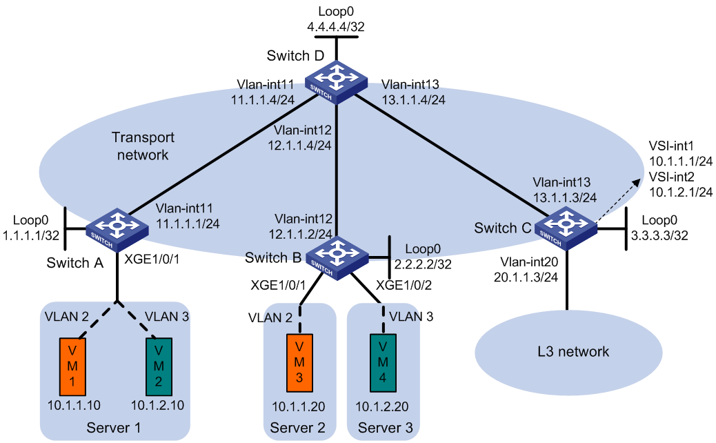
Procedure
1. Set the VXLAN hardware resource mode:
¡ (S6800 and S6860 switch series.) Set the VXLAN hardware resource mode on Switch C and reboot the switch for the mode to take effect.
<SwitchC> system-view
[SwitchC] hardware-resource vxlan l3gw16k
Do you want to change the specified hardware resource working mode? [Y/N]:y
The hardware resource working mode is changed, please save the configuration and
reboot the system to make it effective.
[SwitchC] quit
<SwitchC> reboot
Start to check configuration with next startup configuration file, please wait..
.......DONE!
Current configuration may be lost after the reboot, save current configuration?
[Y/N]:y
This command will reboot the device. Continue? [Y/N]:y
¡ (S6820 switch series.) Set the VXLAN hardware resource mode to l3gw or border on Switch C and reboot the switch for the mode to take effect. (Details not shown.)
2. On VM 1 and VM 3, specify 10.1.1.1 as the gateway address. On VM 2 and VM 4, specify 10.1.2.1 as the gateway address. (Details not shown.)
3. Configure IP addresses and unicast routing settings:
# Assign IP addresses to interfaces, as shown in Figure 19. (Details not shown.)
# Configure OSPF on all transport network switches (Switches A through D) for them to reach one another. (Details not shown.)
4. Configure Switch A:
# Enable L2VPN.
<SwitchA> system-view
[SwitchA] l2vpn enable
# Disable remote MAC address learning.
[SwitchA] vxlan tunnel mac-learning disable
# Create an EVPN instance on VSI vpna, and configure the switch to automatically generate an RD and a route target for the EVPN instance.
[SwitchA] vsi vpna
[SwitchA-vsi-vpna] arp suppression enable
[SwitchA-vsi-vpna] evpn encapsulation vxlan
[SwitchA-vsi-vpna-evpn-vxlan] route-distinguisher auto
[SwitchA-vsi-vpna-evpn-vxlan] vpn-target auto
[SwitchA-vsi-vpna-evpn-vxlan] quit
# Create VXLAN 10.
[SwitchA-vsi-vpna] vxlan 10
[SwitchA-vsi-vpna-vxlan-10] quit
[SwitchA-vsi-vpna] quit
# Create an EVPN instance on VSI vpnb, and configure the switch to automatically generate an RD and a route target for the EVPN instance.
[SwitchA] vsi vpnb
[SwitchA-vsi-vpnb] arp suppression enable
[SwitchA-vsi-vpnb] evpn encapsulation vxlan
[SwitchA-vsi-vpnb-evpn-vxlan] route-distinguisher auto
[SwitchA-vsi-vpnb-evpn-vxlan] vpn-target auto
[SwitchA-vsi-vpnb-evpn-vxlan] quit
# Create VXLAN 20.
[SwitchA-vsi-vpnb] vxlan 20
[SwitchA-vsi-vpnb-vxlan-20] quit
[SwitchA-vsi-vpnb] quit
# Configure BGP to advertise BGP EVPN routes.
[SwitchA] bgp 200
[SwitchA-bgp-default] peer 4.4.4.4 as-number 200
[SwitchA-bgp-default] peer 4.4.4.4 connect-interface loopback 0
[SwitchA-bgp-default] address-family l2vpn evpn
[SwitchA-bgp-default-evpn] peer 4.4.4.4 enable
[SwitchA-bgp-default-evpn] quit
[SwitchA-bgp-default] quit
# On Ten-GigabitEthernet 1/0/1, create Ethernet service instance 1000 to match VLAN 2.
[SwitchA] interface ten-gigabitethernet 1/0/1
[SwitchA-Ten-GigabitEthernet1/0/1] service-instance 1000
[SwitchA-Ten-GigabitEthernet1/0/1-srv1000] encapsulation s-vid 2
# Map Ethernet service instance 1000 to VSI vpna.
[SwitchA-Ten-GigabitEthernet1/0/1-srv1000] xconnect vsi vpna
[SwitchA-Ten-GigabitEthernet1/0/1-srv1000] quit
# On Ten-GigabitEthernet 1/0/1, create Ethernet service instance 2000 to match VLAN 3.
[SwitchA-Ten-GigabitEthernet1/0/1] service-instance 2000
[SwitchA-Ten-GigabitEthernet1/0/1-srv2000] encapsulation s-vid 3
# Map Ethernet service instance 2000 to VSI vpnb.
[SwitchA-Ten-GigabitEthernet1/0/1-srv2000] xconnect vsi vpnb
[SwitchA-Ten-GigabitEthernet1/0/1-srv2000] quit
[SwitchA-Ten-GigabitEthernet1/0/1] quit
5. Configure Switch B:
# Enable L2VPN.
<SwitchB> system-view
[SwitchB] l2vpn enable
# Disable remote MAC address learning.
[SwitchB] vxlan tunnel mac-learning disable
# Create an EVPN instance on VSI vpna, and configure the switch to automatically generate an RD and a route target for the EVPN instance.
[SwitchB] vsi vpna
[SwitchB-vsi-vpna] arp suppression enable
[SwitchB-vsi-vpna] evpn encapsulation vxlan
[SwitchB-vsi-vpna-evpn-vxlan] route-distinguisher auto
[SwitchB-vsi-vpna-evpn-vxlan] vpn-target auto
[SwitchB-vsi-vpna-evpn-vxlan] quit
# Create VXLAN 10.
[SwitchB-vsi-vpna] vxlan 10
[SwitchB-vsi-vpna-vxlan-10] quit
[SwitchB-vsi-vpna] quit
# Create an EVPN instance on VSI vpnb, and configure the switch to automatically generate an RD and a route target for the EVPN instance.
[SwitchB] vsi vpnb
[SwitchB-vsi-vpnb] arp suppression enable
[SwitchB-vsi-vpnb] evpn encapsulation vxlan
[SwitchB-vsi-vpnb-evpn-vxlan] route-distinguisher auto
[SwitchB-vsi-vpnb-evpn-vxlan] vpn-target auto
[SwitchB-vsi-vpnb-evpn-vxlan] quit
# Create VXLAN 20.
[SwitchB-vsi-vpnb] vxlan 20
[SwitchB-vsi-vpnb-vxlan-20] quit
[SwitchB-vsi-vpnb] quit
# Configure BGP to advertise BGP EVPN routes.
[SwitchB] bgp 200
[SwitchB-bgp-default] peer 4.4.4.4 as-number 200
[SwitchB-bgp-default] peer 4.4.4.4 connect-interface loopback 0
[SwitchB-bgp-default] address-family l2vpn evpn
[SwitchB-bgp-default-evpn] peer 4.4.4.4 enable
[SwitchB-bgp-default-evpn] quit
[SwitchB-bgp-default] quit
# On Ten-GigabitEthernet 1/0/1, create Ethernet service instance 1000 to match VLAN 2.
[SwitchB] interface ten-gigabitethernet 1/0/1
[SwitchB-Ten-GigabitEthernet1/0/1] service-instance 1000
[SwitchB-Ten-GigabitEthernet1/0/1-srv1000] encapsulation s-vid 2
# Map Ethernet service instance 1000 to VSI vpna.
[SwitchB-Ten-GigabitEthernet1/0/1-srv1000] xconnect vsi vpna
[SwitchB-Ten-GigabitEthernet1/0/1-srv1000] quit
[SwitchB-Ten-GigabitEthernet1/0/1] quit
# On Ten-GigabitEthernet 1/0/2, create Ethernet service instance 2000 to match VLAN 3.
[SwitchB] interface ten-gigabitethernet 1/0/2
[SwitchB-Ten-GigabitEthernet1/0/2] service-instance 2000
[SwitchB-Ten-GigabitEthernet1/0/2-srv2000] encapsulation s-vid 3
# Map Ethernet service instance 2000 to VSI vpnb.
[SwitchB-Ten-GigabitEthernet1/0/2-srv2000] xconnect vsi vpnb
[SwitchB-Ten-GigabitEthernet1/0/2-srv2000] quit
[SwitchB-Ten-GigabitEthernet1/0/2] quit
6. Configure Switch C:
# Enable L2VPN.
<SwitchC> system-view
[SwitchC] l2vpn enable
# (S6820 switch series.) Reserve the global VLAN interface resources of VLAN 3000 and VLAN 3001.
[SwitchC] reserve-vlan-interface 3000 to 3001 global
# (S6820-32H and S6820-4C switches.) Create VSI gateway service loopback group 1, and assign Layer 2 Ethernet interface Ten-GigabitEthernet 1/0/4 to the service loopback group.
[SwitchC] service-loopback group 1 type vsi-gateway
[SwitchC] interface ten-gigabitethernet 1/0/4
[SwitchC-Ten-GigabitEthernet1/0/4] port service-loopback group 1
All configurations on the interface will be lost. Continue?[Y/N]:y
[SwitchC-Ten-GigabitEthernet1/0/4] quit
# Disable remote MAC address learning.
[SwitchC] vxlan tunnel mac-learning disable
# Create an EVPN instance on VSI vpna, and configure the switch to automatically generate an RD and a route target for the EVPN instance.
[SwitchC] vsi vpna
[SwitchC-vsi-vpna] evpn encapsulation vxlan
[SwitchC-vsi-vpna-evpn-vxlan] route-distinguisher auto
[SwitchC-vsi-vpna-evpn-vxlan] vpn-target auto
[SwitchC-vsi-vpna-evpn-vxlan] quit
# Create VXLAN 10.
[SwitchC-vsi-vpna] vxlan 10
[SwitchC-vsi-vpna-vxlan-10] quit
[SwitchC-vsi-vpna] quit
# Create an EVPN instance on VSI vpnb, and configure the switch to automatically generate an RD and a route target for the EVPN instance.
[SwitchC] vsi vpnb
[SwitchC-vsi-vpnb] evpn encapsulation vxlan
[SwitchC-vsi-vpnb-evpn-vxlan] route-distinguisher auto
[SwitchC-vsi-vpnb-evpn-vxlan] vpn-target auto
[SwitchC-vsi-vpnb-evpn-vxlan] quit
# Create VXLAN 20.
[SwitchC-vsi-vpnb] vxlan 20
[SwitchC-vsi-vpnb-vxlan-20] quit
[SwitchC-vsi-vpnb] quit
# Configure BGP to advertise BGP EVPN routes.
[SwitchC] bgp 200
[SwitchC-bgp-default] peer 4.4.4.4 as-number 200
[SwitchC-bgp-default] peer 4.4.4.4 connect-interface loopback 0
[SwitchC-bgp-default] address-family l2vpn evpn
[SwitchC-bgp-default-evpn] peer 4.4.4.4 enable
[SwitchC-bgp-default-evpn] quit
[SwitchC-bgp-default] quit
# Create VSI-interface 1 and assign the interface an IP address. The IP address will be used as the gateway address for VXLAN 10.
[SwitchC] interface vsi-interface 1
[SwitchC-Vsi-interface1] ip address 10.1.1.1 255.255.255.0
[SwitchC-Vsi-interface1] quit
# Specify VSI-interface 1 as the gateway interface for VSI vpna.
[SwitchC] vsi vpna
[SwitchC-vsi-vpna] gateway vsi-interface 1
[SwitchC-vsi-vpna] quit
# Create VSI-interface 2 and assign the interface an IP address. The IP address will be used as the gateway address for VXLAN 20.
[SwitchC] interface vsi-interface 2
[SwitchC-Vsi-interface2] ip address 10.1.2.1 255.255.255.0
[SwitchC-Vsi-interface2] quit
# Specify VSI-interface 2 as the gateway interface for VSI vpnb.
[SwitchC] vsi vpnb
[SwitchC-vsi-vpnb] gateway vsi-interface 2
[SwitchC-vsi-vpnb] quit
7. Configure Switch D:
# Establish BGP connections with other transport network switches.
<SwitchD> system-view
[SwitchD] bgp 200
[SwitchD-bgp-default] group evpn
[SwitchD-bgp-default] peer 1.1.1.1 group evpn
[SwitchD-bgp-default] peer 2.2.2.2 group evpn
[SwitchD-bgp-default] peer 3.3.3.3 group evpn
[SwitchD-bgp-default] peer evpn as-number 200
[SwitchD-bgp-default] peer evpn connect-interface loopback 0
# Configure BGP to advertise BGP EVPN routes, and disable route target filtering for BGP EVPN routes.
[SwitchD-bgp-default] address-family l2vpn evpn
[SwitchD-bgp-default-evpn] peer evpn enable
[SwitchD-bgp-default-evpn] undo policy vpn-target
# Configure Switch D as an RR.
[SwitchD-bgp-default-evpn] peer evpn reflect-client
[SwitchD-bgp-default-evpn] quit
[SwitchD-bgp-default] quit
Verifying the configuration
1. Verify the EVPN gateway settings on Switch C:
# Verify that Switch C has advertised MAC/IP advertisement routes and IMET routes for the gateways and received MAC/IP advertisement routes and IMET routes from Switch A and Switch B.
[SwitchC] display bgp l2vpn evpn
BGP local router ID is 3.3.3.3
Status codes: * - valid, > - best, d - dampened, h - history
s - suppressed, S - stale, i - internal, e - external
a - additional-path
Origin: i - IGP, e - EGP, ? - incomplete
Total number of routes from all PEs: 10
Route distinguisher: 1:10
Total number of routes: 7
* >i Network : [2][0][48][0000-1234-0001][32][10.1.1.10]/136
NextHop : 1.1.1.1 LocPrf : 100
PrefVal : 0 OutLabel : NULL
MED : 0
Path/Ogn: i
* >i Network : [2][0][48][0000-1234-0003][0][0.0.0.0]/104
NextHop : 2.2.2.2 LocPrf : 100
PrefVal : 0 OutLabel : NULL
MED : 0
Path/Ogn: i
* >i Network : [2][0][48][0000-1234-0003][32][10.1.1.20]/136
NextHop : 2.2.2.2 LocPrf : 100
PrefVal : 0 OutLabel : NULL
MED : 0
Path/Ogn: i
* > Network : [2][0][48][0003-0003-0003][32][10.1.1.1]/136
NextHop : 0.0.0.0 LocPrf : 100
PrefVal : 32768 OutLabel : NULL
MED : 0
Path/Ogn: i
* >i Network : [3][0][32][1.1.1.1]/80
NextHop : 1.1.1.1 LocPrf : 100
PrefVal : 0 OutLabel : NULL
MED : 0
Path/Ogn: i
* >i Network : [3][0][32][2.2.2.2]/80
NextHop : 2.2.2.2 LocPrf : 100
PrefVal : 0 OutLabel : NULL
MED : 0
Path/Ogn: i
* > Network : [3][0][32][3.3.3.3]/80
NextHop : 0.0.0.0 LocPrf : 100
PrefVal : 32768 OutLabel : NULL
MED : 0
Path/Ogn: i
Route distinguisher: 1:20
Total number of routes: 7
* >i Network : [2][0][48][0000-1234-0002][32][10.1.2.10]/136
NextHop : 1.1.1.1 LocPrf : 100
PrefVal : 0 OutLabel : NULL
MED : 0
Path/Ogn: i
* >i Network : [2][0][48][0000-1234-0004][0][0.0.0.0]/104
NextHop : 2.2.2.2 LocPrf : 100
PrefVal : 0 OutLabel : NULL
MED : 0
Path/Ogn: i
* >i Network : [2][0][48][0000-1234-0004][32][10.1.2.20]/136
NextHop : 2.2.2.2 LocPrf : 100
PrefVal : 0 OutLabel : NULL
MED : 0
Path/Ogn: i
* > Network : [2][0][48][0005-0005-0005][32][10.1.2.1]/136
NextHop : 0.0.0.0 LocPrf : 100
PrefVal : 32768 OutLabel : NULL
MED : 0
Path/Ogn: i
* >i Network : [3][0][32][1.1.1.1]/80
NextHop : 1.1.1.1 LocPrf : 100
PrefVal : 0 OutLabel : NULL
MED : 0
Path/Ogn: i
* >i Network : [3][0][32][2.2.2.2]/80
NextHop : 2.2.2.2 LocPrf : 100
PrefVal : 0 OutLabel : NULL
MED : 0
Path/Ogn: i
* > Network : [3][0][32][3.3.3.3]/80
NextHop : 0.0.0.0 LocPrf : 100
PrefVal : 32768 OutLabel : NULL
MED : 0
Path/Ogn: i
# Verify that the VXLAN tunnel interfaces are up on Switch C.
[SwitchC] display interface tunnel
Tunnel0
Current state: UP
Line protocol state: UP
Description: Tunnel0 Interface
Bandwidth: 64 kbps
Maximum transmission unit: 1464
Internet protocol processing: Disabled
Last clearing of counters: Never
Tunnel source 3.3.3.3, destination 2.2.2.2
Tunnel protocol/transport UDP_VXLAN/IP
Last 300 seconds input rate: 0 bytes/sec, 0 bits/sec, 0 packets/sec
Last 300 seconds output rate: 7 bytes/sec, 56 bits/sec, 0 packets/sec
Input: 10 packets, 980 bytes, 0 drops
Output: 85 packets, 6758 bytes, 0 drops
Tunnel1
Current state: UP
Line protocol state: UP
Description: Tunnel1 Interface
Bandwidth: 64 kbps
Maximum transmission unit: 1464
Internet protocol processing: Disabled
Last clearing of counters: Never
Tunnel source 3.3.3.3, destination 1.1.1.1
Tunnel protocol/transport UDP_VXLAN/IP
Last 300 seconds input rate: 1 bytes/sec, 8 bits/sec, 0 packets/sec
Last 300 seconds output rate: 9 bytes/sec, 72 bits/sec, 0 packets/sec
Input: 277 packets, 20306 bytes, 0 drops
Output: 1099 packets, 85962 bytes, 0 drops
# Verify that the VSI interfaces are up on Switch C.
[SwitchC] display interface vsi-interface
Vsi-interface1
Current state: UP
Line protocol state: UP
Description: Vsi-interface1 Interface
Bandwidth: 1000000 kbps
Maximum transmission unit: 1444
Internet address: 10.1.1.1/24 (primary)
IP packet frame type: Ethernet II, hardware address: 0003-0003-0003
IPv6 packet frame type: Ethernet II, hardware address: 0003-0003-0003
Physical: Unknown, baudrate: 1000000 kbps
Last clearing of counters: Never
Input (total): 0 packets, 0 bytes
Output (total): 0 packets, 0 bytes
Vsi-interface2
Current state: UP
Line protocol state: UP
Description: Vsi-interface2 Interface
Bandwidth: 1000000 kbps
Maximum transmission unit: 1444
Internet address: 10.1.2.1/24 (primary)
IP packet frame type: Ethernet II, hardware address: 0005-0005-0005
IPv6 packet frame type: Ethernet II, hardware address: 0005-0005-0005
Physical: Unknown, baudrate: 1000000 kbps
Last clearing of counters: Never
Input (total): 0 packets, 0 bytes
Output (total): 0 packets, 0 bytes
# Verify that the VXLAN tunnels have been assigned to the VXLANs, and that the VSI interfaces are the gateway interfaces of their respective VXLANs.
[SwitchC] display l2vpn vsi verbose
VSI Name: vpna
VSI Index : 0
VSI State : Up
MTU : 1500
Bandwidth : Unlimited
Broadcast Restrain : Unlimited
Multicast Restrain : Unlimited
Unknown Unicast Restrain: Unlimited
MAC Learning : Enabled
MAC Table Limit : -
MAC Learning rate : -
Drop Unknown : -
Flooding : Enabled
Statistics : Disabled
Gateway Interface : VSI-interface 1
VXLAN ID : 10
Tunnels:
Tunnel Name Link ID State Type Flood proxy
Tunnel0 0x5000000 UP Auto Disabled
Tunnel1 0x5000001 UP Auto Disabled
VSI Name: vpnb
VSI Index : 1
VSI State : Up
MTU : 1500
Bandwidth : Unlimited
Broadcast Restrain : Unlimited
Multicast Restrain : Unlimited
Unknown Unicast Restrain: Unlimited
MAC Learning : Enabled
MAC Table Limit : -
MAC Learning rate : -
Drop Unknown : -
Flooding : Enabled
Statistics : Disabled
Gateway Interface : VSI-interface 2
VXLAN ID : 20
Tunnels:
Tunnel Name Link ID State Type Flood proxy
Tunnel0 0x5000000 UP Auto Disabled
Tunnel1 0x5000001 UP Auto Disabled
# Verify that Switch C has created EVPN ARP entries for the VMs.
[SwitchC] display evpn route arp
Flags: D - Dynamic B - BGP L - Local active
G - Gateway S - Static M - Mapping I - Invalid
Public instance Interface: Vsi-interface1
IP address MAC address Router MAC VSI index Flags
10.1.1.1 0003-0003-0003 - 0 GL
10.1.1.10 0000-1234-0001 - 0 B
10.1.1.20 0000-1234-0003 - 0 B
Public instance Interface: Vsi-interface2
IP address MAC address Router MAC VSI index Flags
10.1.2.1 0005-0005-0005 - 1 GL
10.1.2.10 0000-1234-0002 - 1 B
10.1.2.20 0000-1234-0004 - 1 B
# Verify that Switch C has created FIB entries for the VMs.
[SwitchC] display fib 10.1.1.10
Destination count: 1 FIB entry count: 1
Flag:
U:Usable G:Gateway H:Host B:Blackhole D:Dynamic S:Static
R:Relay F:FRR
Destination/Mask Nexthop Flag OutInterface/Token Label
10.1.1.10/32 10.1.1.10 UH Vsi1 Null
2. Verify that VM 1, VM 2, VM 3, and VM 4 can communicate with one another.
Example: Configuring distributed IPv4 EVPN gateways (IPv4 underlay network)
Network configuration
As shown in Figure 20:
· Configure VXLAN 10 and VXLAN 20 on Switch A and Switch B to provide connectivity for the VMs in the VXLANs across the network sites.
· Configure Switch A and Switch B as distributed EVPN gateways to provide gateway services. Configure Switch C as a border gateway to provide access to the connected Layer 3 network.
· Configure Switch D as an RR to reflect BGP EVPN routes between Switch A, Switch B, and Switch C.
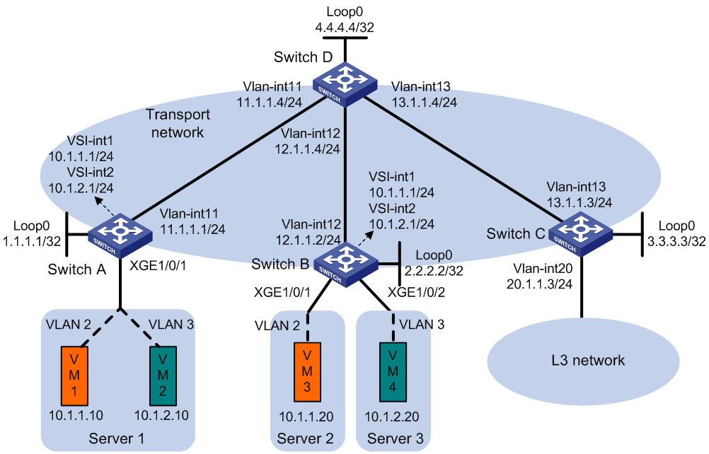
Procedure
1. Set the VXLAN hardware resource mode:
¡ S6800 and S6860 switch series:
# Set the VXLAN hardware resource mode on Switch A and Switch B and reboot the switches for the mode to take effect. This step uses Switch A as an example.
<SwitchA> system-view
[SwitchA] hardware-resource vxlan l3gw16k
Do you want to change the specified hardware resource working mode? [Y/N]:y
The hardware resource working mode is changed, please save the configuration and
reboot the system to make it effective.
[SwitchA] quit
<SwitchA> reboot
Start to check configuration with next startup configuration file, please wait..
.......DONE!
Current configuration may be lost after the reboot, save current configuration?
[Y/N]:y
This command will reboot the device. Continue? [Y/N]:y
# Set the VXLAN hardware resource mode on Switch C and reboot the switch for the mode to take effect.
<SwitchC> system-view
[SwitchC] hardware-resource vxlan border24k
Do you want to change the specified hardware resource working mode? [Y/N]:y
The hardware resource working mode is changed, please save the configuration and
reboot the system to make it effective.
[SwitchC] quit
<SwitchC> reboot
Start to check configuration with next startup configuration file, please wait..
.......DONE!
Current configuration may be lost after the reboot, save current configuration?
[Y/N]:y
This command will reboot the device. Continue? [Y/N]:y
¡ S6820 switch series:
# Set the VXLAN hardware resource mode to l3gw or border on Switch A, Switch B, and Switch C and reboot the switches .for the mode to take effect (Details not shown.)
2. On VM 1 and VM 3, specify 10.1.1.1 as the gateway address. On VM 2 and VM 4, specify 10.1.2.1 as the gateway address. (Details not shown.)
3. Configure IP addresses and unicast routing settings:
# Assign IP addresses to interfaces, as shown in Figure 20. (Details not shown.)
# Configure OSPF on all transport network switches (Switches A through D) for them to reach one another. (Details not shown.)
4. Configure Switch A:
# Enable L2VPN.
<SwitchA> system-view
[SwitchA] l2vpn enable
# (S6820 switch series.) Reserve the global VLAN interface resources of VLAN 3000 through VLAN 3002.
[SwitchA] reserve-vlan-interface 3000 to 3002 global
# (S6820-32H and S6820-4C switches.) Create VSI gateway service loopback group 1, and assign Layer 2 Ethernet interface Ten-GigabitEthernet 1/0/4 to the service loopback group.
[SwitchA] service-loopback group 1 type vsi-gateway
[SwitchA] interface ten-gigabitethernet 1/0/4
[SwitchA-Ten-GigabitEthernet1/0/4] port service-loopback group 1
All configurations on the interface will be lost. Continue?[Y/N]:y
[SwitchA-Ten-GigabitEthernet1/0/4] quit
# Disable remote MAC address learning and remote ARP learning.
[SwitchA] vxlan tunnel mac-learning disable
[SwitchA] vxlan tunnel arp-learning disable
# Create an EVPN instance on VSI vpna, and configure the switch to automatically generate an RD and a route target for the EVPN instance.
[SwitchA] vsi vpna
[SwitchA-vsi-vpna] evpn encapsulation vxlan
[SwitchA-vsi-vpna-evpn-vxlan] route-distinguisher auto
[SwitchA-vsi-vpna-evpn-vxlan] vpn-target auto
[SwitchA-vsi-vpna-evpn-vxlan] quit
# Create VXLAN 10.
[SwitchA-vsi-vpna] vxlan 10
[SwitchA-vsi-vpna-vxlan-10] quit
[SwitchA-vsi-vpna] quit
# Create an EVPN instance on VSI vpnb, and configure the switch to automatically generate an RD and a route target for the EVPN instance.
[SwitchA] vsi vpnb
[SwitchA-vsi-vpnb] evpn encapsulation vxlan
[SwitchA-vsi-vpnb-evpn-vxlan] route-distinguisher auto
[SwitchA-vsi-vpnb-evpn-vxlan] vpn-target auto
[SwitchA-vsi-vpnb-evpn-vxlan] quit
# Create VXLAN 20.
[SwitchA-vsi-vpnb] vxlan 20
[SwitchA-vsi-vpnb-vxlan-20] quit
[SwitchA-vsi-vpnb] quit
# Configure BGP to advertise BGP EVPN routes.
[SwitchA] bgp 200
[SwitchA-bgp-default] peer 4.4.4.4 as-number 200
[SwitchA-bgp-default] peer 4.4.4.4 connect-interface loopback 0
[SwitchA-bgp-default] address-family l2vpn evpn
[SwitchA-bgp-default-evpn] peer 4.4.4.4 enable
[SwitchA-bgp-default-evpn] quit
[SwitchA-bgp-default] quit
# On Ten-GigabitEthernet 1/0/1, create Ethernet service instance 1000 to match VLAN 2.
[SwitchA] interface ten-gigabitethernet 1/0/1
[SwitchA-Ten-GigabitEthernet1/0/1] service-instance 1000
[SwitchA-Ten-GigabitEthernet1/0/1-srv1000] encapsulation s-vid 2
# Map Ethernet service instance 1000 to VSI vpna.
[SwitchA-Ten-GigabitEthernet1/0/1-srv1000] xconnect vsi vpna
[SwitchA-Ten-GigabitEthernet1/0/1-srv1000] quit
# On Ten-GigabitEthernet 1/0/1, create Ethernet service instance 2000 to match VLAN 3.
[SwitchA-Ten-GigabitEthernet1/0/1] service-instance 2000
[SwitchA-Ten-GigabitEthernet1/0/1-srv2000] encapsulation s-vid 3
# Map Ethernet service instance 2000 to VSI vpnb.
[SwitchA-Ten-GigabitEthernet1/0/1-srv2000] xconnect vsi vpnb
[SwitchA-Ten-GigabitEthernet1/0/1-srv2000] quit
[SwitchA-Ten-GigabitEthernet1/0/1] quit
# Configure RD and route target settings for VPN instance vpna.
[SwitchA] ip vpn-instance vpna
[SwitchA-vpn-instance-vpna] route-distinguisher 1:1
[SwitchA-vpn-instance-vpna] address-family ipv4
[SwitchA-vpn-ipv4-vpna] vpn-target 2:2
[SwitchA-vpn-ipv4-vpna] quit
[SwitchA-vpn-instance-vpna] address-family evpn
[SwitchA-vpn-evpn-vpna] vpn-target 1:1
[SwitchA-vpn-evpn-vpna] quit
[SwitchA-vpn-instance-vpna] quit
# Configure VSI-interface 1.
[SwitchA] interface vsi-interface 1
[SwitchA-Vsi-interface1] ip binding vpn-instance vpna
[SwitchA-Vsi-interface1] ip address 10.1.1.1 255.255.255.0
[SwitchA-Vsi-interface1] mac-address 1-1-1
[SwitchA-Vsi-interface1] distributed-gateway local
[SwitchA-Vsi-interface1] local-proxy-arp enable
[SwitchA-Vsi-interface1] quit
# Configure VSI-interface 2.
[SwitchA] interface vsi-interface 2
[SwitchA-Vsi-interface2] ip binding vpn-instance vpna
[SwitchA-Vsi-interface2] ip address 10.1.2.1 255.255.255.0
[SwitchA-Vsi-interface2] mac-address 2-2-2
[SwitchA-Vsi-interface2] distributed-gateway local
[SwitchA-Vsi-interface2] local-proxy-arp enable
[SwitchA-Vsi-interface2] quit
# Associate VSI-interface 3 with VPN instance vpna, and configure the L3 VXLAN ID as 1000 for the VPN instance.
[SwitchA] interface vsi-interface 3
[SwitchA-Vsi-interface3] ip binding vpn-instance vpna
[SwitchA-Vsi-interface3] l3-vni 1000
[SwitchA-Vsi-interface3] quit
# Specify VSI-interface 1 as the gateway interface for VSI vpna.
[SwitchA] vsi vpna
[SwitchA-vsi-vpna] gateway vsi-interface 1
[SwitchA-vsi-vpna] quit
# Specify VSI-interface 2 as the gateway interface for VSI vpnb.
[SwitchA] vsi vpnb
[SwitchA-vsi-vpnb] gateway vsi-interface 2
[SwitchA-vsi-vpnb] quit
5. Configure Switch B:
# Enable L2VPN.
<SwitchB> system-view
[SwitchB] l2vpn enable
# (S6820 switch series.) Reserve the global VLAN interface resources of VLAN 3000 through VLAN 3002.
[SwitchB] reserve-vlan-interface 3000 to 3002 global
# (S6820-32H and S6820-4C switches.) Create VSI gateway service loopback group 1, and assign Layer 2 Ethernet interface Ten-GigabitEthernet 1/0/4 to the service loopback group.
[SwitchB] service-loopback group 1 type vsi-gateway
[SwitchB] interface ten-gigabitethernet 1/0/4
[SwitchB-Ten-GigabitEthernet1/0/4] port service-loopback group 1
All configurations on the interface will be lost. Continue?[Y/N]:y
[SwitchB-Ten-GigabitEthernet1/0/4] quit
# Disable remote MAC address learning and remote ARP learning.
[SwitchB] vxlan tunnel mac-learning disable
[SwitchB] vxlan tunnel arp-learning disable
# Create an EVPN instance on VSI vpna, and configure the switch to automatically generate an RD and a route target for the EVPN instance.
[SwitchB] vsi vpna
[SwitchB-vsi-vpna] evpn encapsulation vxlan
[SwitchB-vsi-vpna-evpn-vxlan] route-distinguisher auto
[SwitchB-vsi-vpna-evpn-vxlan] vpn-target auto
[SwitchB-vsi-vpna-evpn-vxlan] quit
# Create VXLAN 10.
[SwitchB-vsi-vpna] vxlan 10
[SwitchB-vsi-vpna-vxlan-10] quit
[SwitchB-vsi-vpna] quit
# Create an EVPN instance on VSI vpnb, and configure the switch to automatically generate an RD and a route target for the EVPN instance.
[SwitchB] vsi vpnb
[SwitchB-vsi-vpnb] evpn encapsulation vxlan
[SwitchB-vsi-vpnb-evpn-vxlan] route-distinguisher auto
[SwitchB-vsi-vpnb-evpn-vxlan] vpn-target auto
[SwitchB-vsi-vpnb-evpn-vxlan] quit
# Create VXLAN 20.
[SwitchB-vsi-vpnb] vxlan 20
[SwitchB-vsi-vpnb-vxlan-20] quit
[SwitchB-vsi-vpnb] quit
# Configure BGP to advertise BGP EVPN routes.
[SwitchB] bgp 200
[SwitchB-bgp-default] peer 4.4.4.4 as-number 200
[SwitchB-bgp-default] peer 4.4.4.4 connect-interface loopback 0
[SwitchB-bgp-default] address-family l2vpn evpn
[SwitchB-bgp-default-evpn] peer 4.4.4.4 enable
[SwitchB-bgp-default-evpn] quit
[SwitchB-bgp-default] quit
# On Ten-GigabitEthernet 1/0/1, create Ethernet service instance 1000 to match VLAN 2.
[SwitchB] interface ten-gigabitethernet 1/0/1
[SwitchB-Ten-GigabitEthernet1/0/1] service-instance 1000
[SwitchB-Ten-GigabitEthernet1/0/1-srv1000] encapsulation s-vid 2
# Map Ethernet service instance 1000 to VSI vpna.
[SwitchB-Ten-GigabitEthernet1/0/1-srv1000] xconnect vsi vpna
[SwitchB-Ten-GigabitEthernet1/0/1-srv1000] quit
[SwitchB-Ten-GigabitEthernet1/0/1] quit
# On Ten-GigabitEthernet 1/0/2, create Ethernet service instance 2000 to match VLAN 3.
[SwitchB] interface ten-gigabitethernet 1/0/2
[SwitchB-Ten-GigabitEthernet1/0/2] service-instance 2000
[SwitchB-Ten-GigabitEthernet1/0/2-srv2000] encapsulation s-vid 3
# Map Ethernet service instance 2000 to VSI vpnb.
[SwitchB-Ten-GigabitEthernet1/0/2-srv2000] xconnect vsi vpnb
[SwitchB-Ten-GigabitEthernet1/0/2-srv2000] quit
[SwitchB-Ten-GigabitEthernet1/0/2] quit
# Configure RD and route target settings for VPN instance vpna.
[SwitchB] ip vpn-instance vpna
[SwitchB-vpn-instance-vpna] route-distinguisher 1:1
[SwitchB-vpn-instance-vpna] address-family ipv4
[SwitchB-vpn-ipv4-vpna] vpn-target 2:2
[SwitchB-vpn-ipv4-vpna] quit
[SwitchB-vpn-instance-vpna] address-family evpn
[SwitchB-vpn-evpn-vpna] vpn-target 1:1
[SwitchB-vpn-evpn-vpna] quit
[SwitchB-vpn-instance-vpna] quit
# Configure VSI-interface 1.
[SwitchB] interface vsi-interface 1
[SwitchB-Vsi-interface1] ip binding vpn-instance vpna
[SwitchB-Vsi-interface1] ip address 10.1.1.1 255.255.255.0
[SwitchB-Vsi-interface1] mac-address 1-1-1
[SwitchB-Vsi-interface1] distributed-gateway local
[SwitchB-Vsi-interface1] local-proxy-arp enable
[SwitchB-Vsi-interface1] quit
# Configure VSI-interface 2.
[SwitchB] interface vsi-interface 2
[SwitchB-Vsi-interface2] ip binding vpn-instance vpna
[SwitchB-Vsi-interface2] ip address 10.1.2.1 255.255.255.0
[SwitchB-Vsi-interface2] mac-address 2-2-2
[SwitchB-Vsi-interface2] distributed-gateway local
[SwitchB-Vsi-interface2] local-proxy-arp enable
[SwitchB-Vsi-interface2] quit
# Associate VSI-interface 3 with VPN instance vpna, and configure the L3 VXLAN ID as 1000 for the VPN instance.
[SwitchB] interface vsi-interface 3
[SwitchB-Vsi-interface3] ip binding vpn-instance vpna
[SwitchB-Vsi-interface3] l3-vni 1000
[SwitchB-Vsi-interface3] quit
# Specify VSI-interface 1 as the gateway interface for VSI vpna.
[SwitchB] vsi vpna
[SwitchB-vsi-vpna] gateway vsi-interface 1
[SwitchB-vsi-vpna] quit
# Specify VSI-interface 2 as the gateway interface for VSI vpnb.
[SwitchB] vsi vpnb
[SwitchB-vsi-vpnb] gateway vsi-interface 2
[SwitchB-vsi-vpnb] quit
6. Configure Switch C:
# Enable L2VPN.
<SwitchC> system-view
[SwitchC] l2vpn enable
# (S6820 switch series.) Reserve the global VLAN interface resource of VLAN 3000.
[SwitchC] reserve-vlan-interface 3000 global
# (S6820-32H and S6820-4C switches.) Create VSI gateway service loopback group 1, and assign Layer 2 Ethernet interface Ten-GigabitEthernet 1/0/4 to the service loopback group.
[SwitchC] service-loopback group 1 type vsi-gateway
[SwitchC] interface ten-gigabitethernet 1/0/4
[SwitchC-Ten-GigabitEthernet1/0/4] port service-loopback group 1
All configurations on the interface will be lost. Continue?[Y/N]:y
[SwitchC-Ten-GigabitEthernet1/0/4] quit
# Disable remote MAC address learning and remote ARP learning.
[SwitchC] vxlan tunnel mac-learning disable
[SwitchC] vxlan tunnel arp-learning disable
# Configure BGP to advertise BGP EVPN routes.
[SwitchC] bgp 200
[SwitchC-bgp-default] peer 4.4.4.4 as-number 200
[SwitchC-bgp-default] peer 4.4.4.4 connect-interface loopback 0
[SwitchC-bgp-default] address-family l2vpn evpn
[SwitchC-bgp-default-evpn] peer 4.4.4.4 enable
[SwitchC-bgp-default-evpn] quit
[SwitchC-bgp-default] quit
# Configure RD and route target settings for VPN instance vpna.
[SwitchC] ip vpn-instance vpna
[SwitchC-vpn-instance-vpna] route-distinguisher 1:1
[SwitchC-vpn-instance-vpna] address-family ipv4
[SwitchC-vpn-ipv4-vpna] vpn-target 2:2
[SwitchC-vpn-ipv4-vpna] quit
[SwitchC-vpn-instance-vpna] address-family evpn
[SwitchC-vpn-evpn-vpna] vpn-target 1:1
[SwitchC-vpn-evpn-vpna] quit
[SwitchC-vpn-instance-vpna] quit
# Associate VSI-interface 3 with VPN instance vpna, and configure the L3 VXLAN ID as 1000 for the VPN instance.
[SwitchC] interface vsi-interface 3
[SwitchC-Vsi-interface3] ip binding vpn-instance vpna
[SwitchC-Vsi-interface3] l3-vni 1000
[SwitchC-Vsi-interface3] quit
# Configure a default route. The next hop is the IP address of a device in the Layer 3 network.
[SwitchC] ip route-static vpn-instance vpna 0.0.0.0 0 20.1.1.100
# Import the default route to the BGP IPv4 unicast routing table of VPN instance vpna.
[SwitchC] bgp 200
[SwitchC-bgp-default] ip vpn-instance vpna
[SwitchC-bgp-default-vpna] address-family ipv4 unicast
[SwitchC-bgp-default-ipv4-vpna] default-route imported
[SwitchC-bgp-default-ipv4-vpna] import-route static
[SwitchC-bgp-default-ipv4-vpna] quit
[SwitchC-bgp-default-vpna] quit
[SwitchC-bgp-default] quit
# Associate VLAN-interface 20 with VPN instance vpna.
[SwitchC] interface vlan-interface 20
[SwitchC-Vlan-interface20] ip binding vpn-instance vpna
[SwitchC-Vlan-interface20] ip address 20.1.1.3 24
[SwitchC-Vlan-interface20] quit
7. Configure Switch D:
# Establish BGP connections with other transport network switches.
<SwitchD> system-view
[SwitchD] bgp 200
[SwitchD-bgp-default] group evpn
[SwitchD-bgp-default] peer 1.1.1.1 group evpn
[SwitchD-bgp-default] peer 2.2.2.2 group evpn
[SwitchD-bgp-default] peer 3.3.3.3 group evpn
[SwitchD-bgp-default] peer evpn as-number 200
[SwitchD-bgp-default] peer evpn connect-interface loopback 0
# Configure BGP to advertise BGP EVPN routes, and disable route target filtering for BGP EVPN routes.
[SwitchD-bgp-default] address-family l2vpn evpn
[SwitchD-bgp-default-evpn] peer evpn enable
[SwitchD-bgp-default-evpn] undo policy vpn-target
# Configure Switch D as an RR.
[SwitchD-bgp-default-evpn] peer evpn reflect-client
[SwitchD-bgp-default-evpn] quit
[SwitchD-bgp-default] quit
Verifying the configuration
1. Verify the distributed EVPN gateway settings on Switch A:
# Verify that Switch A has advertised the IP prefix advertisement routes for the gateways and the MAC/IP advertisement routes and IMET routes for each VSI. Verify that Switch A has received the IP prefix advertisement routes for the gateways and the MAC/IP advertisement routes and IMET routes for each VSI from Switch B.
[SwitchA] display bgp l2vpn evpn
BGP local router ID is 1.1.1.1
Status codes: * - valid, > - best, d - dampened, h - history,
s - suppressed, S - stale, i - internal, e - external
a - additional-path
Origin: i - IGP, e - EGP, ? - incomplete
Total number of routes from all PEs: 14
Route distinguisher: 1:1
Total number of routes: 4
* > Network : [5][0][24][10.1.1.0]/80
NextHop : 0.0.0.0 LocPrf : 100
PrefVal : 32768 OutLabel : NULL
MED : 0
Path/Ogn: i
* > Network : [5][0][24][10.1.2.0]/80
NextHop : 0.0.0.0 LocPrf : 100
PrefVal : 32768 OutLabel : NULL
MED : 0
Path/Ogn: i
* >i Network : [5][0][24][10.1.1.0]/80
NextHop : 2.2.2.2 LocPrf : 100
PrefVal : 0 OutLabel : NULL
MED : 0
Path/Ogn: i
* >i Network : [5][0][24][10.1.2.0]/80
NextHop : 2.2.2.2 LocPrf : 100
PrefVal : 0 OutLabel : NULL
MED : 0
Path/Ogn: i
Route distinguisher: 1:10
Total number of routes: 5
* > Network : [2][0][48][0000-1234-0001][0][0.0.0.0]/104
NextHop : 0.0.0.0 LocPrf : 100
PrefVal : 32768 OutLabel : NULL
MED : 0
Path/Ogn: i
* > Network : [2][0][48][0000-1234-0001][32][10.1.1.10]/136
NextHop : 0.0.0.0 LocPrf : 100
PrefVal : 32768 OutLabel : NULL
MED : 0
Path/Ogn: i
* >i Network : [2][0][48][0000-1234-0003][32][10.1.1.20]/136
NextHop : 2.2.2.2 LocPrf : 100
PrefVal : 0 OutLabel : NULL
MED : 0
Path/Ogn: i
* > Network : [3][10][32][1.1.1.1]/80
NextHop : 0.0.0.0 LocPrf : 100
PrefVal : 32768 OutLabel : NULL
MED : 0
Path/Ogn: i
* >i Network : [3][10][32][2.2.2.2]/80
NextHop : 2.2.2.2 LocPrf : 100
PrefVal : 0 OutLabel : NULL
MED : 0
Path/Ogn: i
Route distinguisher: 1:20
Total number of routes: 5
* > Network : [2][0][48][0000-1234-0002][0][0.0.0.0]/104
NextHop : 0.0.0.0 LocPrf : 100
PrefVal : 32768 OutLabel : NULL
MED : 0
Path/Ogn: i
* > Network : [2][0][48][0000-1234-0002][32][10.1.2.10]/136
NextHop : 0.0.0.0 LocPrf : 100
PrefVal : 32768 OutLabel : NULL
MED : 0
Path/Ogn: i
* >i Network : [2][0][48][0000-1234-0004][32][10.1.2.20]/136
NextHop : 2.2.2.2 LocPrf : 100
PrefVal : 0 OutLabel : NULL
MED : 0
Path/Ogn: i
* > Network : [3][10][32][1.1.1.1]/80
NextHop : 0.0.0.0 LocPrf : 100
PrefVal : 32768 OutLabel : NULL
MED : 0
Path/Ogn: i
* >i Network : [3][10][32][2.2.2.2]/80
NextHop : 2.2.2.2 LocPrf : 100
PrefVal : 0 OutLabel : NULL
MED : 0
Path/Ogn: i
# Verify that the VXLAN tunnel interfaces are up on Switch A. (This example uses Tunnel 0.)
[SwitchA] display interface tunnel 0
Tunnel0
Current state: UP
Line protocol state: UP
Description: Tunnel0 Interface
Bandwidth: 64 kbps
Maximum transmission unit: 1464
Internet protocol processing: Disabled
Last clearing of counters: Never
Tunnel source 1.1.1.1, destination 2.2.2.2
Tunnel protocol/transport UDP_VXLAN/IP
Last 300 seconds input rate: 0 bytes/sec, 0 bits/sec, 0 packets/sec
Last 300 seconds output rate: 0 bytes/sec, 0 bits/sec, 0 packets/sec
Input: 9 packets, 882 bytes, 0 drops
Output: 9 packets, 882 bytes, 0 drops
# Verify that the VSI interfaces are up on Switch A. (This example uses VSI-interface 1.)
[SwitchA] display interface vsi-interface 1
Vsi-interface1
Current state: UP
Line protocol state: UP
Description: Vsi-interface1 Interface
Bandwidth: 1000000 kbps
Maximum transmission unit: 1444
Internet address: 10.1.1.1/24 (primary)
IP packet frame type: Ethernet II, hardware address: 0001-0001-0001
IPv6 packet frame type: Ethernet II, hardware address: 0001-0001-0001
Physical: Unknown, baudrate: 1000000 kbps
Last clearing of counters: Never
Input (total): 0 packets, 0 bytes
Output (total): 0 packets, 0 bytes
# Verify that the VXLAN tunnels have been assigned to the VXLANs, and that the VSI interfaces are the gateway interfaces of their respective VXLANs.
[SwitchA] display l2vpn vsi verbose
VSI Name: Auto_L3VNI200_3
VSI Index : 1
VSI State : Down
MTU : 1500
Bandwidth : Unlimited
Broadcast Restrain : Unlimited
Multicast Restrain : Unlimited
Unknown Unicast Restrain: Unlimited
MAC Learning : Enabled
MAC Table Limit : -
MAC Learning rate : -
Drop Unknown : -
Flooding : Enabled
Statistics : Disabled
Gateway Interface : VSI-interface 3
VXLAN ID : 1000
VSI Name: vpna
VSI Index : 0
VSI State : Up
MTU : 1500
Bandwidth : Unlimited
Broadcast Restrain : Unlimited
Multicast Restrain : Unlimited
Unknown Unicast Restrain: Unlimited
MAC Learning : Enabled
MAC Table Limit : -
MAC Learning rate : -
Drop Unknown : -
Flooding : Enabled
Statistics : Disabled
Gateway Interface : VSI-interface 1
VXLAN ID : 10
Tunnels:
Tunnel Name Link ID State Type Flood proxy
Tunnel0 0x5000001 Up Auto Disabled
Tunnel1 0x5000002 Up Auto Disabled
ACs:
AC Link ID State Type
XGE1/0/1 srv1000 0 Up Manual
VSI Name: vpnb
VSI Index : 0
VSI State : Up
MTU : 1500
Bandwidth : Unlimited
Broadcast Restrain : Unlimited
Multicast Restrain : Unlimited
Unknown Unicast Restrain: Unlimited
MAC Learning : Enabled
MAC Table Limit : -
MAC Learning rate : -
Drop Unknown : -
Flooding : Enabled
Statistics : Disabled
Gateway Interface : VSI-interface 2
VXLAN ID : 20
Tunnels:
Tunnel Name Link ID State Type Flood proxy
Tunnel0 0x5000001 Up Auto Disabled
Tunnel1 0x5000002 Up Auto Disabled
ACs:
AC Link ID State Type
XGE1/0/1 srv2000 0 Up Manual
# Verify that Switch A has created ARP entries for the VMs.
[SwitchA] display arp
Type: S-Static D-Dynamic O-Openflow R-Rule M-Multiport I-Invalid
IP address MAC address VLAN/VSI Interface/Link ID Aging Type
10.1.1.10 0000-1234-0001 0 0 20 D
10.1.2.10 0000-1234-0002 0 0 19 D
2.2.2.2 a0ce-5e24-0100 1 Tunnel0 -- R
# Verify that Switch A has created EVPN ARP entries for the local VMs.
[SwitchA] display evpn route arp
Flags: D - Dynamic B - BGP L - Local active
G - Gateway S - Static M - Mapping I - Invalid
VPN instance: vpna Interface: Vsi-interface1
IP address MAC address Router MAC VSI Index Flags
10.1.1.1 0001-0001-0001 a0ce-7e40-0400 0 GL
10.1.1.10 0000-1234-0001 a0ce-7e40-0400 0 DL
10.1.2.10 0000-1234-0002 a0ce-7e40-0400 0 DL
10.1.1.20 0000-1234-0003 a0ce-7e40-0400 0 B
10.1.2.20 0000-1234-0004 a0ce-7e40-0400 0 B
2. Verify that VM 1, VM 2, VM 3, and VM 4 can communicate with one another. (Details not shown.)
Example: Configuring distributed IPv6 EVPN gateways (IPv4 underlay network)
Network configuration
As shown in Figure 21:
· Configure VXLAN 10 and VXLAN 20 on Switch A and Switch B to provide connectivity for the VMs in the VXLANs across the network sites.
· Configure Switch A and Switch B as distributed EVPN gateways to provide gateway services. Configure Switch C as a border gateway to provide access to the connected Layer 3 network.
· Configure Switch D as an RR to reflect BGP EVPN routes between Switch A, Switch B, and Switch C.
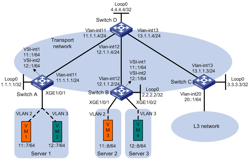
Procedure
1. Set the VXLAN hardware resource mode:
¡ S6800 and S6860 switch series:
# Set the VXLAN hardware resource mode on Switch A and Switch B and reboot the switches for the mode to take effect. This step uses Switch A as an example.
<SwitchA> system-view
[SwitchA] hardware-resource vxlan l3gw16k
Do you want to change the specified hardware resource working mode? [Y/N]:y
The hardware resource working mode is changed, please save the configuration and
reboot the system to make it effective.
[SwitchA] quit
<SwitchA> reboot
Start to check configuration with next startup configuration file, please wait..
.......DONE!
Current configuration may be lost after the reboot, save current configuration?
[Y/N]:y
This command will reboot the device. Continue? [Y/N]:y
# Set the VXLAN hardware resource mode on Switch C and reboot the switch for the mode to take effect.
<SwitchC> system-view
[SwitchC] hardware-resource vxlan border24k
Do you want to change the specified hardware resource working mode? [Y/N]:y
The hardware resource working mode is changed, please save the configuration and
reboot the system to make it effective.
[SwitchC] quit
<SwitchC> reboot
Start to check configuration with next startup configuration file, please wait..
.......DONE!
Current configuration may be lost after the reboot, save current configuration?
[Y/N]:y
This command will reboot the device. Continue? [Y/N]:y
¡ S6820 switch series:
# Set the VXLAN hardware resource mode to l3gw or border on Switch A, Switch B, and Switch C and reboot the switches for the mode to take effect. (Details not shown.)
2. On VM 1 and VM 3, specify 11::1 as the gateway address. On VM 2 and VM 4, specify 12::1 as the gateway address. (Details not shown.)
3. Configure IP addresses and unicast routing settings:
# Assign IP addresses to interfaces, as shown in Figure 21. (Details not shown.)
# Configure OSPF on all transport network switches (Switches A through D) for them to reach one another. (Details not shown.)
4. Configure Switch A:
# Enable L2VPN.
<SwitchA> system-view
[SwitchA] l2vpn enable
# (S6820 switch series.) Reserve the global VLAN interface resources of VLAN 3000 through VLAN 3002.
[SwitchA] reserve-vlan-interface 3000 to 3002 global
# (S6820-32H and S6820-4C switches.) Create VSI gateway service loopback group 1, and assign Layer 2 Ethernet interface Ten-GigabitEthernet 1/0/4 to the service loopback group.
[SwitchA] service-loopback group 1 type vsi-gateway
[SwitchA] interface ten-gigabitethernet 1/0/4
[SwitchA-Ten-GigabitEthernet1/0/4] port service-loopback group 1
All configurations on the interface will be lost. Continue?[Y/N]:y
[SwitchA-Ten-GigabitEthernet1/0/4] quit
# Disable remote MAC address learning and remote ND learning.
[SwitchA] vxlan tunnel mac-learning disable
[SwitchA] vxlan tunnel nd-learning disable
# Create an EVPN instance on VSI vpna, and configure the switch to automatically generate an RD and a route target for the EVPN instance.
[SwitchA] vsi vpna
[SwitchA-vsi-vpna] evpn encapsulation vxlan
[SwitchA-vsi-vpna-evpn-vxlan] route-distinguisher auto
[SwitchA-vsi-vpna-evpn-vxlan] vpn-target auto
[SwitchA-vsi-vpna-evpn-vxlan] quit
# Create VXLAN 10.
[SwitchA-vsi-vpna] vxlan 10
[SwitchA-vsi-vpna-vxlan-10] quit
[SwitchA-vsi-vpna] quit
# Create an EVPN instance on VSI vpnb, and configure the switch to automatically generate an RD and a route target for the EVPN instance.
[SwitchA] vsi vpnb
[SwitchA-vsi-vpnb] evpn encapsulation vxlan
[SwitchA-vsi-vpnb-evpn-vxlan] route-distinguisher auto
[SwitchA-vsi-vpnb-evpn-vxlan] vpn-target auto
[SwitchA-vsi-vpnb-evpn-vxlan] quit
# Create VXLAN 20.
[SwitchA-vsi-vpnb] vxlan 20
[SwitchA-vsi-vpnb-vxlan-20] quit
[SwitchA-vsi-vpnb] quit
# Configure BGP to advertise BGP EVPN routes.
[SwitchA] bgp 200
[SwitchA-bgp-default] peer 4.4.4.4 as-number 200
[SwitchA-bgp-default] peer 4.4.4.4 connect-interface loopback 0
[SwitchA-bgp-default] address-family l2vpn evpn
[SwitchA-bgp-default-evpn] peer 4.4.4.4 enable
[SwitchA-bgp-default-evpn] quit
[SwitchA-bgp-default] quit
# On Ten-GigabitEthernet 1/0/1, create Ethernet service instance 1000 to match VLAN 2.
[SwitchA] interface ten-gigabitethernet 1/0/1
[SwitchA-Ten-GigabitEthernet1/0/1] service-instance 1000
[SwitchA-Ten-GigabitEthernet1/0/1-srv1000] encapsulation s-vid 2
# Map Ethernet service instance 1000 to VSI vpna.
[SwitchA-Ten-GigabitEthernet1/0/1-srv1000] xconnect vsi vpna
[SwitchA-Ten-GigabitEthernet1/0/1-srv1000] quit
# On Ten-GigabitEthernet 1/0/1, create Ethernet service instance 2000 to match VLAN 3.
[SwitchA-Ten-GigabitEthernet1/0/1] service-instance 2000
[SwitchA-Ten-GigabitEthernet1/0/1-srv2000] encapsulation s-vid 3
# Map Ethernet service instance 2000 to VSI vpnb.
[SwitchA-Ten-GigabitEthernet1/0/1-srv2000] xconnect vsi vpnb
[SwitchA-Ten-GigabitEthernet1/0/1-srv2000] quit
[SwitchA-Ten-GigabitEthernet1/0/1] quit
# Configure RD and route target settings for VPN instance vpna.
[SwitchA] ip vpn-instance vpna
[SwitchA-vpn-instance-vpna] route-distinguisher 1:1
[SwitchA-vpn-instance-vpna] address-family ipv6
[SwitchA-vpn-ipv6-vpna] vpn-target 2:2
[SwitchA-vpn-ipv6-vpna] quit
[SwitchA-vpn-instance-vpna] address-family evpn
[SwitchA-vpn-evpn-vpna] vpn-target 1:1
[SwitchA-vpn-evpn-vpna] quit
[SwitchA-vpn-instance-vpna] quit
# Configure VSI-interface 1.
[SwitchA] interface vsi-interface 1
[SwitchA-Vsi-interface1] ip binding vpn-instance vpna
[SwitchA-Vsi-interface1] ipv6 address 11::1 64
[SwitchA-Vsi-interface1] mac-address 1-1-1
[SwitchA-Vsi-interface1] distributed-gateway local
[SwitchA-Vsi-interface1] local-proxy-nd enable
[SwitchA-Vsi-interface1] quit
# Configure VSI-interface 2.
[SwitchA] interface vsi-interface 2
[SwitchA-Vsi-interface2] ip binding vpn-instance vpna
[SwitchA-Vsi-interface2] ipv6 address 12::1 64
[SwitchA-Vsi-interface2] mac-address 2-2-2
[SwitchA-Vsi-interface2] distributed-gateway local
[SwitchA-Vsi-interface2] local-proxy-nd enable
[SwitchA-Vsi-interface2] quit
# Associate VSI-interface 3 with VPN instance vpna, and configure the L3 VXLAN ID as 1000 for the VPN instance.
[SwitchA] interface vsi-interface 3
[SwitchA-Vsi-interface3] ip binding vpn-instance vpna
[SwitchA-Vsi-interface3] ipv6 address auto link-local
[SwitchA-Vsi-interface3] l3-vni 1000
[SwitchA-Vsi-interface3] quit
# Specify VSI-interface 1 as the gateway interface for VSI vpna.
[SwitchA] vsi vpna
[SwitchA-vsi-vpna] gateway vsi-interface 1
[SwitchA-vsi-vpna] quit
# Specify VSI-interface 2 as the gateway interface for VSI vpnb.
[SwitchA] vsi vpnb
[SwitchA-vsi-vpnb] gateway vsi-interface 2
[SwitchA-vsi-vpnb] quit
5. Configure Switch B:
# Enable L2VPN.
<SwitchB> system-view
[SwitchB] l2vpn enable
# (S6820 switch series.) Reserve the global VLAN interface resources of VLAN 3000 through VLAN 3002.
[SwitchB] reserve-vlan-interface 3000 to 3002 global
# (S6820-32H and S6820-4C switches.) Create VSI gateway service loopback group 1, and assign Layer 2 Ethernet interface Ten-GigabitEthernet 1/0/4 to the service loopback group.
[SwitchB] service-loopback group 1 type vsi-gateway
[SwitchB] interface ten-gigabitethernet 1/0/4
[SwitchB-Ten-GigabitEthernet1/0/4] port service-loopback group 1
All configurations on the interface will be lost. Continue?[Y/N]:y
[SwitchB-Ten-GigabitEthernet1/0/4] quit
# Disable remote MAC address learning and remote ND learning.
[SwitchB] vxlan tunnel mac-learning disable
[SwitchB] vxlan tunnel nd-learning disable
# Create an EVPN instance on VSI vpna, and configure the switch to automatically generate an RD and a route target for the EVPN instance.
[SwitchB] vsi vpna
[SwitchB-vsi-vpna] evpn encapsulation vxlan
[SwitchB-vsi-vpna-evpn-vxlan] route-distinguisher auto
[SwitchB-vsi-vpna-evpn-vxlan] vpn-target auto
[SwitchB-vsi-vpna-evpn-vxlan] quit
# Create VXLAN 10.
[SwitchB-vsi-vpna] vxlan 10
[SwitchB-vsi-vpna-vxlan-10] quit
[SwitchB-vsi-vpna] quit
# Create an EVPN instance on VSI vpnb, and configure the switch to automatically generate an RD and a route target for the EVPN instance.
[SwitchB] vsi vpnb
[SwitchB-vsi-vpnb] evpn encapsulation vxlan
[SwitchB-vsi-vpnb-evpn-vxlan] route-distinguisher auto
[SwitchB-vsi-vpnb-evpn-vxlan] vpn-target auto
[SwitchB-vsi-vpnb-evpn-vxlan] quit
# Create VXLAN 20.
[SwitchB-vsi-vpnb] vxlan 20
[SwitchB-vsi-vpnb-vxlan-20] quit
[SwitchB-vsi-vpnb] quit
# Configure BGP to advertise BGP EVPN routes.
[SwitchB] bgp 200
[SwitchB-bgp-default] peer 4.4.4.4 as-number 200
[SwitchB-bgp-default] peer 4.4.4.4 connect-interface loopback 0
[SwitchB-bgp-default] address-family l2vpn evpn
[SwitchB-bgp-default-evpn] peer 4.4.4.4 enable
[SwitchB-bgp-default-evpn] quit
[SwitchB-bgp-default] quit
# On Ten-GigabitEthernet 1/0/1, create Ethernet service instance 1000 to match VLAN 2.
[SwitchB] interface ten-gigabitethernet 1/0/1
[SwitchB-Ten-GigabitEthernet1/0/1] service-instance 1000
[SwitchB-Ten-GigabitEthernet1/0/1-srv1000] encapsulation s-vid 2
# Map Ethernet service instance 1000 to VSI vpna.
[SwitchB-Ten-GigabitEthernet1/0/1-srv1000] xconnect vsi vpna
[SwitchB-Ten-GigabitEthernet1/0/1-srv1000] quit
[SwitchB-Ten-GigabitEthernet1/0/1] quit
# On Ten-GigabitEthernet 1/0/2, create Ethernet service instance 2000 to match VLAN 3.
[SwitchB] interface ten-gigabitethernet 1/0/2
[SwitchB-Ten-GigabitEthernet1/0/2] service-instance 2000
[SwitchB-Ten-GigabitEthernet1/0/2-srv2000] encapsulation s-vid 3
# Map Ethernet service instance 2000 to VSI vpnb.
[SwitchB-Ten-GigabitEthernet1/0/2-srv2000] xconnect vsi vpnb
[SwitchB-Ten-GigabitEthernet1/0/2-srv2000] quit
[SwitchB-Ten-GigabitEthernet1/0/2] quit
# Configure RD and route target settings for VPN instance vpna.
[SwitchB] ip vpn-instance vpna
[SwitchB-vpn-instance-vpna] route-distinguisher 1:1
[SwitchB-vpn-instance-vpna] address-family ipv6
[SwitchB-vpn-ipv6-vpna] vpn-target 2:2
[SwitchB-vpn-ipv6-vpna] quit
[SwitchB-vpn-instance-vpna] address-family evpn
[SwitchB-vpn-evpn-vpna] vpn-target 1:1
[SwitchB-vpn-evpn-vpna] quit
[SwitchB-vpn-instance-vpna] quit
# Configure VSI-interface 1.
[SwitchB] interface vsi-interface 1
[SwitchB-Vsi-interface1] ip binding vpn-instance vpna
[SwitchB-Vsi-interface1] ipv6 address 11::1 64
[SwitchB-Vsi-interface1] mac-address 1-1-1
[SwitchB-Vsi-interface1] distributed-gateway local
[SwitchB-Vsi-interface1] local-proxy-nd enable
[SwitchB-Vsi-interface1] quit
# Configure VSI-interface 2.
[SwitchB] interface vsi-interface 2
[SwitchB-Vsi-interface2] ip binding vpn-instance vpna
[SwitchB-Vsi-interface2] ipv6 address 12::1 64
[SwitchB-Vsi-interface2] mac-address 2-2-2
[SwitchB-Vsi-interface2] distributed-gateway local
[SwitchB-Vsi-interface2] local-proxy-nd enable
[SwitchB-Vsi-interface2] quit
# Associate VSI-interface 3 with VPN instance vpna, and configure the L3 VXLAN ID as 1000 for the VPN instance.
[SwitchB] interface vsi-interface 3
[SwitchB-Vsi-interface3] ip binding vpn-instance vpna
[SwitchB-Vsi-interface3] ipv6 address auto link-local
[SwitchB-Vsi-interface3] l3-vni 1000
[SwitchB-Vsi-interface3] quit
# Specify VSI-interface 1 as the gateway interface for VSI vpna.
[SwitchB] vsi vpna
[SwitchB-vsi-vpna] gateway vsi-interface 1
[SwitchB-vsi-vpna] quit
# Specify VSI-interface 2 as the gateway interface for VSI vpnb.
[SwitchB] vsi vpnb
[SwitchB-vsi-vpnb] gateway vsi-interface 2
[SwitchB-vsi-vpnb] quit
6. Configure Switch C:
# Enable L2VPN.
<SwitchC> system-view
[SwitchC] l2vpn enable
# (S6820 switch series.) Reserve the global VLAN interface resource of VLAN 3000.
[SwitchC] reserve-vlan-interface 3000 global
# (S6820-32H and S6820-4C switches.) Create VSI gateway service loopback group 1, and assign Layer 2 Ethernet interface Ten-GigabitEthernet 1/0/4 to the service loopback group.
[SwitchC] service-loopback group 1 type vsi-gateway
[SwitchC] interface ten-gigabitethernet 1/0/4
[SwitchC-Ten-GigabitEthernet1/0/4] port service-loopback group 1
All configurations on the interface will be lost. Continue?[Y/N]:y
[SwitchC-Ten-GigabitEthernet1/0/4] quit
# Disable remote MAC address learning and remote ND learning.
[SwitchC] vxlan tunnel mac-learning disable
[SwitchC] vxlan tunnel nd-learning disable
# Configure BGP to advertise BGP EVPN routes.
[SwitchC] bgp 200
[SwitchC-bgp-default] peer 4.4.4.4 as-number 200
[SwitchC-bgp-default] peer 4.4.4.4 connect-interface loopback 0
[SwitchC-bgp-default] address-family l2vpn evpn
[SwitchC-bgp-default-evpn] peer 4.4.4.4 enable
[SwitchC-bgp-default-evpn] quit
[SwitchC-bgp-default] quit
# Configure RD and route target settings for VPN instance vpna.
[SwitchC] ip vpn-instance vpna
[SwitchC-vpn-instance-vpna] route-distinguisher 1:1
[SwitchC-vpn-instance-vpna] address-family ipv6
[SwitchC-vpn-ipv6-vpna] vpn-target 2:2
[SwitchC-vpn-ipv6-vpna] quit
[SwitchC-vpn-instance-vpna] address-family evpn
[SwitchC-vpn-evpn-vpna] vpn-target 1:1
[SwitchC-vpn-evpn-vpna] quit
[SwitchC-vpn-instance-vpna] quit
# Associate VSI-interface 3 with VPN instance vpna, and configure the L3 VXLAN ID as 1000 for the VPN instance.
[SwitchC] interface vsi-interface 3
[SwitchC-Vsi-interface3] ip binding vpn-instance vpna
[SwitchC-Vsi-interface3] ipv6 address auto link-local
[SwitchC-Vsi-interface3] l3-vni 1000
[SwitchC-Vsi-interface3] quit
# Configure a default route. The next hop is the IP address of a device in the Layer 3 network.
[SwitchC] ipv6 route-static vpn-instance vpna :: 0 20::100
# Import the default route to the BGP IPv6 unicast routing table of VPN instance vpna.
[SwitchC] bgp 200
[SwitchC-bgp-default] ip vpn-instance vpna
[SwitchC-bgp-default-vpna] address-family ipv6 unicast
[SwitchC-bgp-default-ipv6-vpna] default-route imported
[SwitchC-bgp-default-ipv6-vpna] import-route static
[SwitchC-bgp-default-ipv6-vpna] quit
[SwitchC-bgp-default-vpna] quit
[SwitchC-bgp-default] quit
# Associate VLAN-interface 20 with VPN instance vpna.
[SwitchC] interface vlan-interface 20
[SwitchC-Vlan-interface20] ip binding vpn-instance vpna
[SwitchC-Vlan-interface20] ipv6 address 20::1 64
[SwitchC-Vlan-interface20] quit
7. Configure Switch D:
# Establish BGP connections with other transport network switches.
<SwitchD> system-view
[SwitchD] bgp 200
[SwitchD-bgp-default] group evpn
[SwitchD-bgp-default] peer 1.1.1.1 group evpn
[SwitchD-bgp-default] peer 2.2.2.2 group evpn
[SwitchD-bgp-default] peer 3.3.3.3 group evpn
[SwitchD-bgp-default] peer evpn as-number 200
[SwitchD-bgp-default] peer evpn connect-interface loopback 0
# Configure BGP to advertise BGP EVPN routes, and disable route target filtering for BGP EVPN routes.
[SwitchD-bgp-default] address-family l2vpn evpn
[SwitchD-bgp-default-evpn] peer evpn enable
[SwitchD-bgp-default-evpn] undo policy vpn-target
# Configure Switch D as an RR.
[SwitchD-bgp-default-evpn] peer evpn reflect-client
[SwitchD-bgp-default-evpn] quit
[SwitchD-bgp-default] quit
Verifying the configuration
1. Verify the distributed EVPN gateway settings on Switch A:
# Verify that Switch A has advertised the IP prefix advertisement routes for the gateways and the MAC/IP advertisement routes and IMET routes for each VSI. Verify that Switch A has received the IP prefix advertisement routes for the gateways and the MAC/IP advertisement routes and IMET routes for each VSI from Switch B.
[SwitchA] display bgp l2vpn evpn
BGP local router ID is 1.1.1.1
Status codes: * - valid, > - best, d - dampened, h - history,
s - suppressed, S - stale, i - internal, e - external
a - additional-path
Origin: i - IGP, e - EGP, ? - incomplete
Total number of routes from all PEs: 14
Route distinguisher: 1:1
Total number of routes: 4
* > Network : [5][0][64][11::0]/176
NextHop : 0.0.0.0 LocPrf : 100
PrefVal : 32768 OutLabel : NULL
MED : 0
Path/Ogn: i
* > Network : [5][0][64][12::0]/176
NextHop : 0.0.0.0 LocPrf : 100
PrefVal : 32768 OutLabel : NULL
MED : 0
Path/Ogn: i
* >i Network : [5][0][64][11::0]/176
NextHop : 2.2.2.2 LocPrf : 100
PrefVal : 0 OutLabel : NULL
MED : 0
Path/Ogn: i
* >i Network : [5][0][64][12::0]/176
NextHop : 2.2.2.2 LocPrf : 100
PrefVal : 0 OutLabel : NULL
MED : 0
Path/Ogn: i
Route distinguisher: 1:10
Total number of routes: 5
* > Network : [2][0][48][8291-87ab-0206][128][11::7]/232
NextHop : 0.0.0.0 LocPrf : 100
PrefVal : 32768 OutLabel : NULL
MED : 0
Path/Ogn: i
* >i Network : [2][0][48][8291-920d-0306][128][11::8]/232
NextHop : 2::2 LocPrf : 100
PrefVal : 0 OutLabel : NULL
MED : 0
Path/Ogn: i
* > Network : [3][10][32][1.1.1.1]/80
NextHop : 0.0.0.0 LocPrf : 100
PrefVal : 32768 OutLabel : NULL
MED : 0
Path/Ogn: i
* >i Network : [3][10][32][2.2.2.2]/80
NextHop : 2.2.2.2 LocPrf : 100
PrefVal : 32768 OutLabel : NULL
MED : 0
Path/Ogn: i
Route distinguisher: 1:20
Total number of routes: 5
* > [2][0][48][8291-87ab-0206][128][12::7]/232
NextHop : 0.0.0.0 LocPrf : 100
PrefVal : 32768 OutLabel : NULL
MED : 0
Path/Ogn: i
* >i Network : [2][0][48][8291-920d-0306][128][12::8]/232
NextHop : 2::2 LocPrf : 100
PrefVal : 0 OutLabel : NULL
MED : 0
Path/Ogn: i
* > [3][10][32][1.1.1.1]/80
NextHop : 0.0.0.0 LocPrf : 100
PrefVal : 32768 OutLabel : NULL
MED : 0
Path/Ogn: i
* >i Network : [3][10][32][2.2.2.2]/80
NextHop : 2.2.2.2 LocPrf : 100
PrefVal : 32768 OutLabel : NULL
MED : 0
Path/Ogn: i
# Verify that the VXLAN tunnel interfaces are up on Switch A. (This example uses Tunnel 0.)
[SwitchA] display interface tunnel 0
Tunnel0
Current state: UP
Line protocol state: UP
Description: Tunnel0 Interface
Bandwidth: 64 kbps
Maximum transmission unit: 1464
Internet protocol processing: Disabled
Last clearing of counters: Never
Tunnel source 1.1.1.1, destination 2.2.2.2
Tunnel protocol/transport UDP_VXLAN/IP
Last 300 seconds input rate: 0 bytes/sec, 0 bits/sec, 0 packets/sec
Last 300 seconds output rate: 0 bytes/sec, 0 bits/sec, 0 packets/sec
Input: 9 packets, 882 bytes, 0 drops
Output: 9 packets, 882 bytes, 0 drops
# Verify that the VSI interfaces are up on Switch A. (This example uses VSI-interface 1.)
[SwitchA] display interface vsi-interface 1
Vsi-interface1
Current state: UP
Line protocol state: UP
Description: Vsi-interface1 Interface
Bandwidth: 1000000 kbps
Maximum transmission unit: 1444
Internet address: 10.1.1.1/24 (primary)
IP packet frame type: Ethernet II, hardware address: 0001-0001-0001
IPv6 packet frame type: Ethernet II, hardware address: 0001-0001-0001
Physical: Unknown, baudrate: 1000000 kbps
Last clearing of counters: Never
Input (total): 0 packets, 0 bytes
Output (total): 0 packets, 0 bytes
# Verify that the VXLAN tunnels have been assigned to the VXLANs, and that the VSI interfaces are the gateway interfaces of their respective VXLANs.
[SwitchA] display l2vpn vsi verbose
VSI Name: Auto_L3VNI200_3
VSI Index : 1
VSI State : Down
MTU : 1500
Bandwidth : Unlimited
Broadcast Restrain : Unlimited
Multicast Restrain : Unlimited
Unknown Unicast Restrain: Unlimited
MAC Learning : Enabled
MAC Table Limit : -
MAC Learning rate : -
Drop Unknown : -
Flooding : Enabled
Statistics : Disabled
Gateway Interface : VSI-interface 3
VXLAN ID : 1000
VSI Name: vpna
VSI Index : 0
VSI State : Up
MTU : 1500
Bandwidth : Unlimited
Broadcast Restrain : Unlimited
Multicast Restrain : Unlimited
Unknown Unicast Restrain: Unlimited
MAC Learning : Enabled
MAC Table Limit : -
MAC Learning rate : -
Drop Unknown : -
Flooding : Enabled
Statistics : Disabled
Gateway Interface : VSI-interface 1
VXLAN ID : 10
Tunnels:
Tunnel Name Link ID State Type Flood proxy
Tunnel0 0x5000001 Up Auto Disabled
Tunnel1 0x5000002 Up Auto Disabled
ACs:
AC Link ID State Type
XGE1/0/1 srv1000 0 Up Manual
VSI Name: vpnb
VSI Index : 0
VSI State : Up
MTU : 1500
Bandwidth : Unlimited
Broadcast Restrain : Unlimited
Multicast Restrain : Unlimited
Unknown Unicast Restrain: Unlimited
MAC Learning : Enabled
MAC Table Limit : -
MAC Learning rate : -
Drop Unknown : -
Flooding : Enabled
Statistics : Disabled
Gateway Interface : VSI-interface 2
VXLAN ID : 20
Tunnels:
Tunnel Name Link ID State Type Flood proxy
Tunnel0 0x5000001 Up Auto Disabled
Tunnel1 0x5000002 Up Auto Disabled
ACs:
AC Link ID State Type
XGE1/0/1 srv2000 0 Up Manual
# Verify that Switch A has created EVPN ND entries for the local VMs.
[SwitchA] display evpn route nd
Flags: D - Dynamic B - BGP L - Local active
G - Gateway S - Static M - Mapping
VPN instance: vpna Interface: Vsi-interface1
IPv6 address : 11::1
MAC address : 0001-0001-0001 Router MAC : 06dc-93de-0100
VSI index : 0 Flags : GL
IPv6 address : 11::7
MAC address : 06dc-98ca-0206 Router MAC : 06dc-93de-0100
VSI index : 0 Flags : DL
IPv6 address : 11::8
MAC address : 06dc-a8dd-0506 Router MAC : 06dc-a235-0400
VSI index : 0 Flags : B
VPN instance: vpnb Interface: Vsi-interface2
IPv6 address : 12::1
MAC address : 0002-0002-0002 Router MAC : 06dc-93de-0100
VSI index : 1 Flags : GL
IPv6 address : 12::7
MAC address : 06dc-9ca0-0306 Router MAC : 06dc-93de-0100
VSI index : 1 Flags : DL
IPv6 address : 12::8
MAC address : 06dc-ad91-0606 Router MAC : 06dc-a235-0400
VSI index : 1 Flags : B
2. Verify that VM 1, VM 2, VM 3, and VM 4 can communicate with one another. (Details not shown.)
Example: Configuring communication between IPv4 EVPN networks and the public network
Network configuration
As shown in Figure 22:
· Configure VXLAN 10, VXLAN 20, and VXLAN 30 on Switch A, Switch B, and Switch C to meet the following requirements:
¡ VXLAN 10 and VXLAN 20 are on the private network, and VXLAN 30 is on the public network.
¡ VXLAN 10 can communicate with VXLAN 20 and VXLAN 30, and VXLAN 20 is isolated from VXLAN 30.
· Configure Switch A, Switch B, and Switch C as distributed EVPN gateways to provide gateway services for the VXLANs.
· Configure Switch D as an RR to reflect BGP EVPN routes between Switch A, Switch B, and Switch C.
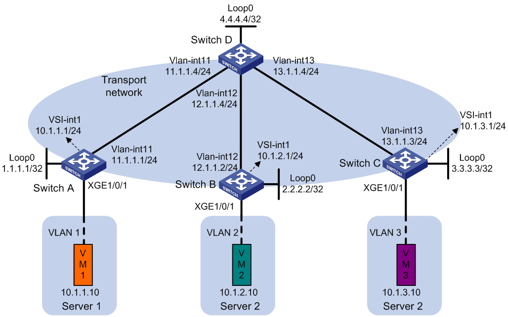
Procedure
1. Set the VXLAN hardware resource mode:
¡ (S6800 and S6860 switch series.) Set the VXLAN hardware resource mode on Switch A, Switch B, and Switch C and reboot the switches for the mode to take effect. This step uses Switch A as an example.
<SwitchA> system-view
[SwitchA] hardware-resource vxlan l3gw16k
Do you want to change the specified hardware resource working mode? [Y/N]:y
The hardware resource working mode is changed, please save the configuration and
reboot the system to make it effective.
[SwitchA] quit
<SwitchA> reboot
Start to check configuration with next startup configuration file, please wait..
.......DONE!
Current configuration may be lost after the reboot, save current configuration?
[Y/N]:y
This command will reboot the device. Continue? [Y/N]:y
¡ (S6820 switch series.) Set the VXLAN hardware resource mode to l3gw or border on Switch A, Switch B, and Switch C and reboot the switches for the mode to take effect. (Details not shown.)
2. On VM 1, VM 2, and VM 3, specify 10.1.1.1, 10.1.2.1, and 10.1.3.1 as the gateway address, respectively. (Details not shown.)
3. Configure IP addresses and unicast routing settings:
# Assign IP addresses to interfaces, as shown in Figure 22. (Details not shown.)
# Configure OSPF on all transport network switches (Switches A through D) for them to reach one another. (Details not shown.)
4. Configure Switch A:
# Enable L2VPN.
<SwitchA> system-view
[SwitchA] l2vpn enable
# (S6820 switch series.) Reserve the global VLAN interface resources of VLAN 3000 through VLAN 3003.
[SwitchA] reserve-vlan-interface 3000 to 3003 global
# (S6820-32H and S6820-4C switches.) Create VSI gateway service loopback group 1, and assign Layer 2 Ethernet interface Ten-GigabitEthernet 1/0/4 to the service loopback group.
[SwitchA] service-loopback group 1 type vsi-gateway
[SwitchA] interface ten-gigabitethernet 1/0/4
[SwitchA-Ten-GigabitEthernet1/0/4] port service-loopback group 1
All configurations on the interface will be lost. Continue?[Y/N]:y
[SwitchA-Ten-GigabitEthernet1/0/4] quit
# Disable remote MAC address learning and remote ARP learning.
[SwitchA] vxlan tunnel mac-learning disable
[SwitchA] vxlan tunnel arp-learning disable
# Create an EVPN instance on VSI vpna, and configure the switch to automatically generate an RD and a route target for the EVPN instance.
[SwitchA] vsi vpna
[SwitchA-vsi-vpna] evpn encapsulation vxlan
[SwitchA-vsi-vpna-evpn-vxlan] route-distinguisher auto
[SwitchA-vsi-vpna-evpn-vxlan] vpn-target auto
[SwitchA-vsi-vpna-evpn-vxlan] quit
# Create VXLAN 10.
[SwitchA-vsi-vpna] vxlan 10
[SwitchA-vsi-vpna-vxlan-10] quit
[SwitchA-vsi-vpna] quit
# Configure BGP to advertise BGP EVPN routes.
[SwitchA] bgp 200
[SwitchA-bgp-default] peer 4.4.4.4 as-number 200
[SwitchA-bgp-default] peer 4.4.4.4 connect-interface loopback 0
[SwitchA-bgp-default] address-family l2vpn evpn
[SwitchA-bgp-default-evpn] peer 4.4.4.4 enable
[SwitchA-bgp-default-evpn] quit
[SwitchA-bgp-default] quit
# On Ten-GigabitEthernet 1/0/1, create Ethernet service instance 1000 to match VLAN 1.
[SwitchA] interface ten-gigabitethernet 1/0/1
[SwitchA-Ten-GigabitEthernet1/0/1] service-instance 1000
[SwitchA-Ten-GigabitEthernet1/0/1-srv1000] encapsulation s-vid 1
# Map Ethernet service instance 1000 to VSI vpna.
[SwitchA-Ten-GigabitEthernet1/0/1-srv1000] xconnect vsi vpna
[SwitchA-Ten-GigabitEthernet1/0/1-srv1000] quit
# Configure RD and route target settings for VPN instance vpna.
[SwitchA] ip vpn-instance vpna
[SwitchA-vpn-instance-vpna] route-distinguisher 1:1
[SwitchA-vpn-instance-vpna] address-family ipv4
[SwitchA-vpn-ipv4-vpna] vpn-target 1:1
[SwitchA-vpn-ipv4-vpna] vpn-target 2:2 import-extcommunity
[SwitchA-vpn-ipv4-vpna] vpn-target 3:3 import-extcommunity
[SwitchA-vpn-ipv4-vpna] quit
[SwitchA-vpn-instance-vpna] address-family evpn
[SwitchA-vpn-evpn-vpna] vpn-target 1:1
[SwitchA-vpn-evpn-vpna] vpn-target 2:2 import-extcommunity
[SwitchA-vpn-evpn-vpna] vpn-target 3:3 import-extcommunity
[SwitchA-vpn-evpn-vpna] quit
[SwitchA-vpn-instance-vpna] quit
# Configure VSI-interface 1.
[SwitchA] interface vsi-interface 1
[SwitchA-Vsi-interface1] ip binding vpn-instance vpna
[SwitchA-Vsi-interface1] ip address 10.1.1.1 255.255.255.0
[SwitchA-Vsi-interface1] distributed-gateway local
[SwitchA-Vsi-interface1] local-proxy-arp enable
[SwitchA-Vsi-interface1] quit
# Associate VSI-interface 2 with VPN instance vpna, and configure the L3 VXLAN ID as 1000 for the VPN instance.
[SwitchA] interface vsi-interface 2
[SwitchA-Vsi-interface2] ip binding vpn-instance vpna
[SwitchA-Vsi-interface2] l3-vni 1000
[SwitchA-Vsi-interface2] quit
# Create VSI-interface 3 and configure its L3 VXLAN ID as 2000 for matching routes from Switch B.
[SwitchA] interface vsi-interface 3
[SwitchA-Vsi-interface3] l3-vni 2000
[SwitchA-Vsi-interface3] quit
# Create VSI-interface 4 and configure its L3 VXLAN ID as 3000 for matching routes from Switch C.
[SwitchA] interface vsi-interface 4
[SwitchA-Vsi-interface4] l3-vni 3000
[SwitchA-Vsi-interface4] quit
# Specify VSI-interface 1 as the gateway interface for VSI vpna.
[SwitchA] vsi vpna
[SwitchA-vsi-vpna] gateway vsi-interface 1
[SwitchA-vsi-vpna] quit
5. Configure Switch B:
# Enable L2VPN.
<SwitchB> system-view
[SwitchB] l2vpn enable
# (S6820 switch series.) Reserve the global VLAN interface resources of VLAN 3000 through VLAN 3003.
[SwitchB] reserve-vlan-interface 3000 to 3003 global
# (S6820-32H and S6820-4C switches.) Create VSI gateway service loopback group 1, and assign Layer 2 Ethernet interface Ten-GigabitEthernet 1/0/4 to the service loopback group.
[SwitchB] service-loopback group 1 type vsi-gateway
[SwitchB] interface ten-gigabitethernet 1/0/4
[SwitchB-Ten-GigabitEthernet1/0/4] port service-loopback group 1
All configurations on the interface will be lost. Continue?[Y/N]:y
[SwitchB-Ten-GigabitEthernet1/0/4] quit
# Disable remote MAC address learning and remote ARP learning.
[SwitchB] vxlan tunnel mac-learning disable
[SwitchB] vxlan tunnel arp-learning disable
# Create an EVPN instance on VSI vpnb, and configure the switch to automatically generate an RD and a route target for the EVPN instance.
[SwitchB] vsi vpnb
[SwitchB-vsi-vpnb] evpn encapsulation vxlan
[SwitchB-vsi-vpnb-evpn-vxlan] route-distinguisher auto
[SwitchB-vsi-vpnb-evpn-vxlan] vpn-target auto
[SwitchB-vsi-vpnb-evpn-vxlan] quit
# Create VXLAN 20.
[SwitchB-vsi-vpnb] vxlan 20
[SwitchB-vsi-vpnb-vxlan-20] quit
[SwitchB-vsi-vpnb] quit
# Configure BGP to advertise BGP EVPN routes.
[SwitchB] bgp 200
[SwitchB-bgp-default] peer 4.4.4.4 as-number 200
[SwitchB-bgp-default] peer 4.4.4.4 connect-interface loopback 0
[SwitchB-bgp-default] address-family l2vpn evpn
[SwitchB-bgp-default-evpn] peer 4.4.4.4 enable
[SwitchB-bgp-default-evpn] quit
[SwitchB-bgp-default] quit
# On Ten-GigabitEthernet 1/0/1, create Ethernet service instance 1000 to match VLAN 2.
[SwitchB] interface ten-gigabitethernet 1/0/1
[SwitchB-Ten-GigabitEthernet1/0/1] service-instance 1000
[SwitchB-Ten-GigabitEthernet1/0/1-srv1000] encapsulation s-vid 2
# Map Ethernet service instance 1000 to VSI vpnb.
[SwitchB-Ten-GigabitEthernet1/0/1-srv1000] xconnect vsi vpnb
[SwitchB-Ten-GigabitEthernet1/0/1-srv1000] quit
[SwitchB-Ten-GigabitEthernet1/0/1] quit
# Configure RD and route target settings for VPN instance vpnb.
[SwitchB] ip vpn-instance vpnb
[SwitchB-vpn-instance-vpnb] route-distinguisher 2:2
[SwitchB-vpn-instance-vpnb] address-family ipv4
[SwitchB-vpn-ipv4-vpnb] vpn-target 2:2
[SwitchB-vpn-ipv4-vpnb] vpn-target 1:1 import-extcommunity
[SwitchB-vpn-ipv4-vpnb] quit
[SwitchB-vpn-instance-vpnb] address-family evpn
[SwitchB-vpn-evpn-vpnb] vpn-target 2:2
[SwitchB-vpn-evpn-vpnb] vpn-target 1:1 import-extcommunity
[SwitchB-vpn-evpn-vpnb] quit
[SwitchB-vpn-instance-vpnb] quit
# Configure VSI-interface 1.
[SwitchB] interface vsi-interface 1
[SwitchB-Vsi-interface1] ip binding vpn-instance vpnb
[SwitchB-Vsi-interface1] ip address 10.1.2.1 255.255.255.0
[SwitchB-Vsi-interface1] distributed-gateway local
[SwitchB-Vsi-interface1] local-proxy-arp enable
[SwitchB-Vsi-interface1] quit
# Create VSI-interface 2, and configure its L3 VXLAN ID as 1000 for matching routes from Switch A.
[SwitchB] interface vsi-interface 2
[SwitchB-Vsi-interface2] l3-vni 1000
[SwitchB-Vsi-interface2] qui
# Associate VSI-interface 3 with VPN instance vpnb, and configure the L3 VXLAN ID as 2000 for the VPN instance.
[SwitchB] interface vsi-interface 3
[SwitchB-Vsi-interface3] ip binding vpn-instance vpnb
[SwitchB-Vsi-interface3] l3-vni 2000
[SwitchB-Vsi-interface3] quit
# Create VSI-interface 4, and configure its L3 VXLAN ID as 3000 for matching routes from Switch C.
[SwitchB] interface vsi-interface 4
[SwitchB-Vsi-interface4] l3-vni 3000
[SwitchB-Vsi-interface4] quit
# Specify VSI-interface 1 as the gateway interface for VSI vpnb.
[SwitchB] vsi vpnb
[SwitchB-vsi-vpnb] gateway vsi-interface 1
[SwitchB-vsi-vpnb] quit
6. Configure Switch C:
# Enable L2VPN.
<SwitchC> system-view
[SwitchC] l2vpn enable
# (S6820 switch series.) Reserve the global VLAN interface resources of VLAN 3000 through VLAN 3003.
[SwitchC] reserve-vlan-interface 3000 to 3003 global
# (S6820-32H and S6820-4C switches.) Create VSI gateway service loopback group 1, and assign Layer 2 Ethernet interface Ten-GigabitEthernet 1/0/4 to the service loopback group.
[SwitchC] service-loopback group 1 type vsi-gateway
[SwitchC] interface ten-gigabitethernet 1/0/4
[SwitchC-Ten-GigabitEthernet1/0/4] port service-loopback group 1
All configurations on the interface will be lost. Continue?[Y/N]:y
[SwitchC-Ten-GigabitEthernet1/0/4] quit
# Disable remote MAC address learning and remote ARP learning.
[SwitchC] vxlan tunnel mac-learning disable
[SwitchC] vxlan tunnel arp-learning disable
# Create an EVPN instance on VSI vpnc, and configure the switch to automatically generate an RD and a route target for the EVPN instance.
[SwitchC] vsi vpnc
[SwitchC-vsi-vpnc] evpn encapsulation vxlan
[SwitchC-vsi-vpnc-evpn-vxlan] route-distinguisher auto
[SwitchC-vsi-vpnc-evpn-vxlan] vpn-target auto
[SwitchC-vsi-vpnc-evpn-vxlan] quit
# Create VXLAN 30.
[SwitchC-vsi-vpnc] vxlan 30
[SwitchC-vsi-vpnc-vxlan-30] quit
[SwitchC-vsi-vpnc] quit
# Configure BGP to advertise BGP EVPN routes.
[SwitchC] bgp 200
[SwitchC-bgp-default] peer 4.4.4.4 as-number 200
[SwitchC-bgp-default] peer 4.4.4.4 connect-interface loopback 0
[SwitchC-bgp-default] address-family ipv4 unicast
[SwitchC-bgp-default-ipv4] quit
[SwitchC-bgp-default] address-family l2vpn evpn
[SwitchC-bgp-default-evpn] peer 4.4.4.4 enable
[SwitchC-bgp-default-evpn] quit
[SwitchC-bgp-default] quit
# Configure RD, route target, and L3 VXLAN ID settings for the public instance.
[SwitchC] ip public-instance
[SwitchC-public-instance] route-distinguisher 3:3
[SwitchC-public-instance] l3-vni 3000
[SwitchC-public-instance] address-family ipv4
[SwitchC-public-instance-ipv4] vpn-target 3:3
[SwitchC-public-instance-ipv4] vpn-target 1:1 import-extcommunity
[SwitchC-public-instance-ipv4] quit
[SwitchC-public-instance] address-family evpn
[SwitchC-public-instance-evpn]vpn-target 3:3
[SwitchC-public-instance-evpn] vpn-target 1:1 import-extcommunity
[SwitchC-public-instance-evpn] quit
[SwitchC-public-instance] quit
# On Ten-GigabitEthernet 1/0/1, create Ethernet service instance 1000 to match VLAN 3.
[SwitchC] interface ten-gigabitethernet 1/0/1
[SwitchC-Ten-GigabitEthernet1/0/1] service-instance 1000
[SwitchC-Ten-GigabitEthernet1/0/1-srv1000] encapsulation s-vid 3
# Map Ethernet service instance 1000 to VSI vpnc.
[SwitchC-Ten-GigabitEthernet1/0/1-srv1000] xconnect vsi vpnc
[SwitchC-Ten-GigabitEthernet1/0/1-srv1000] quit
[SwitchC-Ten-GigabitEthernet1/0/1] quit
# Configure VSI-interface 1.
[SwitchC] interface vsi-interface 1
[SwitchC-Vsi-interface1] ip address 10.1.3.1 255.255.255.0
[SwitchC-Vsi-interface1] distributed-gateway local
[SwitchC-Vsi-interface1] local-proxy-arp enable
[SwitchC-Vsi-interface1] quit
# Create VSI-interface 2, and configure its L3 VXLAN ID as 1000 for matching routes from Switch A.
[SwitchC] interface vsi-interface 2
[SwitchC-Vsi-interface2] l3-vni 1000
[SwitchC-Vsi-interface2] quit
# Create VSI-interface 3, and configure its L3 VXLAN ID as 2000 for matching routes from Switch B.
[SwitchC] interface vsi-interface 3
[SwitchC-Vsi-interface3] l3-vni 2000
[SwitchC-Vsi-interface3] quit
# Create VSI-interface 4 for the public instance, and configure the L3 VXLAN ID as 3000 for the VSI interface.
[SwitchC] interface vsi-interface 4
[SwitchC-Vsi-interface4] l3-vni 3000
[SwitchC-Vsi-interface4] quit
# Specify VSI-interface 1 as the gateway interface for VSI vpnc.
[SwitchC] vsi vpnc
[SwitchC-vsi-vpnc] gateway vsi-interface 1
[SwitchC-vsi-vpnc] quit
7. Configure Switch D:
# Establish BGP connections with other transport network switches.
<SwitchD> system-view
[SwitchD] bgp 200
[SwitchD-bgp-default] group evpn
[SwitchD-bgp-default] peer 1.1.1.1 group evpn
[SwitchD-bgp-default] peer 2.2.2.2 group evpn
[SwitchD-bgp-default] peer 3.3.3.3 group evpn
[SwitchD-bgp-default] peer evpn as-number 200
[SwitchD-bgp-default] peer evpn connect-interface loopback 0
# Configure BGP to advertise BGP EVPN routes, and disable route target filtering for BGP EVPN routes.
[SwitchD-bgp-default] address-family l2vpn evpn
[SwitchD-bgp-default-evpn] peer evpn enable
[SwitchD-bgp-default-evpn] undo policy vpn-target
# Configure Switch D as an RR.
[SwitchD-bgp-default-evpn] peer evpn reflect-client
[SwitchD-bgp-default-evpn] quit
[SwitchD-bgp-default] quit
Verifying the configuration
1. Verify the distributed EVPN gateway settings on Switch A:
# Verify that Switch A has advertised the IP prefix advertisement routes for the gateways and the MAC/IP advertisement routes and IMET routes for each VSI. Verify that Switch A has received the IP prefix advertisement routes for the gateways and the MAC/IP advertisement routes and IMET routes for each VSI from Switch B and Switch C.
[SwitchA] display bgp l2vpn evpn
BGP local router ID is 1.1.1.1
Status codes: * - valid, > - best, d - dampened, h - history,
s - suppressed, S - stale, i - internal, e - external
a - additional-path
Origin: i - IGP, e - EGP, ? - incomplete
Total number of routes from all PEs: 9
Route distinguisher: 1:1(vpna)
Total number of routes: 3
* >i Network : [2][0][48][582e-d6b2-0906][32][10.1.2.10]/136
NextHop : 2.2.2.2 LocPrf : 100
PrefVal : 0 OutLabel : NULL
MED : 0
Path/Ogn: i
* >i Network : [2][0][48][9a50-488c-1106][32][10.1.3.10]/136
NextHop : 3.3.3.3 LocPrf : 100
PrefVal : 0 OutLabel : NULL
MED : 0
Path/Ogn: i
* > Network : [5][0][24][10.1.1.0]/80
NextHop : 0.0.0.0 LocPrf : 100
PrefVal : 32768 OutLabel : NULL
MED : 0
Path/Ogn: i
Route distinguisher: 1:10
Total number of routes: 2
* > Network : [2][0][48][582e-aaec-0806][32][10.1.1.10]/136
NextHop : 0.0.0.0 LocPrf : 100
PrefVal : 32768 OutLabel : NULL
MED : 0
Path/Ogn: i
* > Network : [3][0][32][1.1.1.1]/80
NextHop : 0.0.0.0 LocPrf : 100
PrefVal : 32768 OutLabel : NULL
MED : 0
Path/Ogn: i
Route distinguisher: 1:20
Total number of routes: 1
* >i Network : [2][0][48][582e-d6b2-0906][32][10.1.2.10]/136
NextHop : 2.2.2.2 LocPrf : 100
PrefVal : 0 OutLabel : NULL
MED : 0
Path/Ogn: i
Route distinguisher: 1:30
Total number of routes: 1
* >i Network : [2][0][48][9a50-488c-1106][32][10.1.3.10]/136
NextHop : 3.3.3.3 LocPrf : 100
PrefVal : 0 OutLabel : NULL
MED : 0
Path/Ogn: i
Route distinguisher: 2:2
Total number of routes: 1
* >i Network : [5][0][24][10.1.2.0]/80
NextHop : 2.2.2.2 LocPrf : 100
PrefVal : 0 OutLabel : NULL
MED : 0
Path/Ogn: i
Route distinguisher: 3:3
Total number of routes: 1
* >i Network : [5][0][24][10.1.3.0]/80
NextHop : 3.3.3.3 LocPrf : 100
PrefVal : 0 OutLabel : NULL
MED : 0
Path/Ogn: i
# Verify that the VXLAN tunnel interfaces are up on Switch A.
[SwitchA] display interface tunnel
Tunnel0
Current state: UP
Line protocol state: UP
Description: Tunnel0 Interface
Bandwidth: 64 kbps
Maximum transmission unit: 1464
Internet protocol processing: Disabled
Last clearing of counters: Never
Tunnel source 1.1.1.1, destination 2.2.2.2
Tunnel protocol/transport UDP_VXLAN/IP
Last 300 seconds input rate: 0 bytes/sec, 0 bits/sec, 0 packets/sec
Last 300 seconds output rate: 0 bytes/sec, 0 bits/sec, 0 packets/sec
Input: 15 packets, 1470 bytes, 0 drops
Output: 15 packets, 1470 bytes, 0 drops
Tunnel1
Current state: UP
Line protocol state: UP
Description: Tunnel1 Interface
Bandwidth: 64 kbps
Maximum transmission unit: 1464
Internet protocol processing: Disabled
Last clearing of counters: Never
Tunnel source 1.1.1.1, destination 3.3.3.3
Tunnel protocol/transport UDP_VXLAN/IP
Last 300 seconds input rate: 0 bytes/sec, 0 bits/sec, 0 packets/sec
Last 300 seconds output rate: 0 bytes/sec, 0 bits/sec, 0 packets/sec
Input: 22 packets, 2156 bytes, 0 drops
Output: 23 packets, 2254 bytes, 0 drops
# Verify that the VSI interfaces are up on Switch A.
[SwitchA] display interface vsi-interface
Vsi-interface1
Current state: UP
Line protocol state: UP
Description: Vsi-interface1 Interface
Bandwidth: 1000000 kbps
Maximum transmission unit: 1444
Internet address: 10.1.1.1/24 (primary)
IP packet frame type: Ethernet II, hardware address: 582e-81f2-0600
IPv6 packet frame type: Ethernet II, hardware address: 582e-81f2-0600
Physical: Unknown, baudrate: 1000000 kbps
Last clearing of counters: Never
Input (total): 0 packets, 0 bytes
Output (total): 0 packets, 0 bytes
Vsi-interface2
Current state: UP
Line protocol state: UP
Description: Vsi-interface2 Interface
Bandwidth: 1000000 kbps
Maximum transmission unit: 1444
Internet protocol processing: Disabled
IP packet frame type: Ethernet II, hardware address: 582e-81f2-0600
IPv6 packet frame type: Ethernet II, hardware address: 582e-81f2-0600
Physical: Unknown, baudrate: 1000000 kbps
Last clearing of counters: Never
Input (total): 0 packets, 0 bytes
Output (total): 0 packets, 0 bytes
Vsi-interface3
Current state: UP
Line protocol state: UP
Description: Vsi-interface3 Interface
Bandwidth: 1000000 kbps
Maximum transmission unit: 1444
Internet protocol processing: Disabled
IP packet frame type: Ethernet II, hardware address: 582e-81f2-0600
IPv6 packet frame type: Ethernet II, hardware address: 582e-81f2-0600
Physical: Unknown, baudrate: 1000000 kbps
Last clearing of counters: Never
Input (total): 0 packets, 0 bytes
Output (total): 0 packets, 0 bytes
Vsi-interface4
Current state: UP
Line protocol state: UP
Description: Vsi-interface4 Interface
Bandwidth: 1000000 kbps
Maximum transmission unit: 1444
Internet protocol processing: Disabled
IP packet frame type: Ethernet II, hardware address: 582e-81f2-0600
IPv6 packet frame type: Ethernet II, hardware address: 582e-81f2-0600
Physical: Unknown, baudrate: 1000000 kbps
Last clearing of counters: Never
Input (total): 0 packets, 0 bytes
Output (total): 0 packets, 0 bytes
# Verify that the VXLAN tunnels have been assigned to the VXLANs, and that the VSI interfaces are the gateway interfaces of their respective VXLANs.
[SwitchA] display l2vpn vsi verbose
VSI Name: Auto_L3VNI1000_2
VSI Index : 1
VSI State : Down
MTU : 1500
Bandwidth : Unlimited
Broadcast Restrain : Unlimited
Multicast Restrain : Unlimited
Unknown Unicast Restrain: Unlimited
MAC Learning : Enabled
MAC Table Limit : -
MAC Learning rate : -
Drop Unknown : -
Flooding : Enabled
Statistics : Disabled
Gateway Interface : VSI-interface 2
VXLAN ID : 1000
VSI Name: Auto_L3VNI2000_3
VSI Index : 2
VSI State : Down
MTU : 1500
Bandwidth : Unlimited
Broadcast Restrain : Unlimited
Multicast Restrain : Unlimited
Unknown Unicast Restrain: Unlimited
MAC Learning : Enabled
MAC Table Limit : -
MAC Learning rate : -
Drop Unknown : -
Flooding : Enabled
Statistics : Disabled
Gateway Interface : VSI-interface 3
VXLAN ID : 2000
VSI Name: Auto_L3VNI3000_4
VSI Index : 3
VSI State : Down
MTU : 1500
Bandwidth : Unlimited
Broadcast Restrain : Unlimited
Multicast Restrain : Unlimited
Unknown Unicast Restrain: Unlimited
MAC Learning : Enabled
MAC Table Limit : -
MAC Learning rate : -
Drop Unknown : -
Flooding : Enabled
Statistics : Disabled
Gateway Interface : VSI-interface 4
VXLAN ID : 3000
VSI Name: vpna
VSI Index : 0
VSI State : Up
MTU : 1500
Bandwidth : Unlimited
Broadcast Restrain : Unlimited
Multicast Restrain : Unlimited
Unknown Unicast Restrain: Unlimited
MAC Learning : Enabled
MAC Table Limit : -
MAC Learning rate : -
Drop Unknown : -
Flooding : Enabled
Statistics : Disabled
Gateway Interface : VSI-interface 1
VXLAN ID : 10
ACs:
AC Link ID State Type
XGE1/0/1 srv1000 0 Up Manual
# Verify that Switch A has created ARP entries for the VMs.
[SwitchA] display arp
Type: S-Static D-Dynamic O-Openflow R-Rule M-Multiport I-Invalid
IP address MAC address VLAN/VSI Interface/Link ID Aging Type
10.1.1.10 582e-aaec-0806 0 0 10 D
11.1.1.4 582c-1385-0517 -- Vlan11 14 D
2.2.2.2 582e-8ba6-0700 2 Tunnel0 -- R
3.3.3.3 9a51-95ba-1000 3 Tunnel1 -- R
2. Verify that VM 1 can communicate with VM 2 and VM 3, and VM 2 cannot communicate with VM 3. (Details not shown.)
Example: Configuring IPv4 EVPN distributed relay using an Ethernet aggregate link as the IPL
Network configuration
As shown in Figure 23, perform the following tasks to make sure the VMs can communicate with one another:
· Configure VXLAN 10 on Switch A and Switch B, and configure VXLAN 20 on Switch D.
· Configure EVPN distributed relay on Switch A and Switch B to virtualize them into one VTEP. The switches use an Ethernet aggregate link as the IPL.
· Configure Switch C as a centralized EVPN gateway and RR.
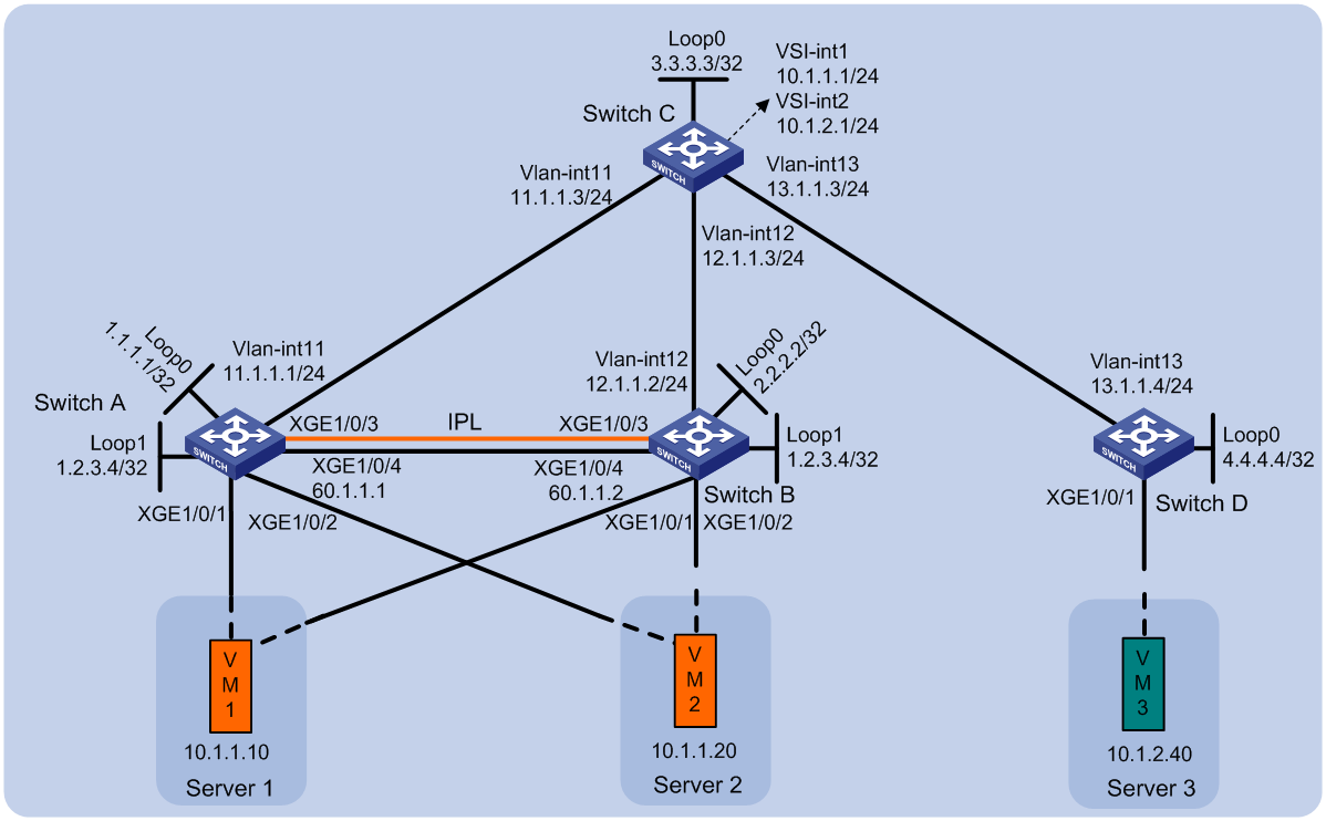
Procedure
1. Set the VXLAN hardware resource mode:
¡ (S6800 and S6860 switch series.) Set the VXLAN hardware resource mode on Switch C and reboot the switch for the mode to take effect.
<SwitchC> system-view
[SwitchC] hardware-resource vxlan l3gw16k
Do you want to change the specified hardware resource working mode? [Y/N]:y
The hardware resource working mode is changed, please save the configuration and
reboot the system to make it effective.
[SwitchC] quit
<SwitchC> reboot
Start to check configuration with next startup configuration file, please wait..
.......DONE!
Current configuration may be lost after the reboot, save current configuration?
[Y/N]:y
This command will reboot the device. Continue? [Y/N]:y
¡ (S6820 switch series.) Set the VXLAN hardware resource mode to l3gw or border on Switch C and reboot the switch for the mode to take effect. (Details not shown.)
2. On VM 1 and VM 2, specify 10.1.1.1 as the gateway address. On VM 3, specify 10.1.2.1 as the gateway address. (Details not shown.)
3. Configure IP addresses and unicast routing settings:
# Assign IP addresses to interfaces (including loopback interfaces), as shown in Figure 23. (Details not shown.)
# Configure OSPF on all transport network switches (Switches A through D) for them to reach one another. (Details not shown.)
4. Configure Switch A:
# Enable L2VPN.
<SwitchA> system-view
[SwitchA] l2vpn enable
# Disable remote MAC learning and remote ARP learning.
[SwitchA] vxlan tunnel mac-learning disable
[SwitchA] vxlan tunnel arp-learning disable
# Enable EVPN distributed relay, and specify the virtual VTEP address as 1.2.3.4.
[SwitchA] evpn drni group 1.2.3.4
# Configure DR system parameters.
[SwitchA] drni system-mac 0001-0001-0001
[SwitchA] drni system-number 1
[SwitchA] drni system-priority 10
[SwitchA] drni keepalive ip destination 60.1.1.2 source 60.1.1.1
[SwitchA] drni restore-delay 180
# Create Layer 2 dynamic aggregate interface Bridge-Aggregation 3.
[SwitchA] interface bridge-aggregation 3
[SwitchA-Bridge-Aggregation3] link-aggregation mode dynamic
[SwitchA-Bridge-Aggregation3] quit
# Assign Ten-GigabitEthernet 1/0/3 to link aggregation group 3.
[SwitchA] interface ten-gigabitethernet 1/0/3
[SwitchA-Ten-GigabitEthernet1/0/3] port link-aggregation group 3
[SwitchA-Ten-GigabitEthernet1/0/3] quit
# Specify Bridge-Aggregation 3 as the IPP and disable static source check on it.
[SwitchA] interface bridge-aggregation 3
[SwitchA-Bridge-Aggregation3] port drni intra-portal-port 1
[SwitchA-Bridge-Aggregation3] undo mac-address static source-check enable
[SwitchA-Bridge-Aggregation3] quit
# Configure routing for Switch A to reach Switch B at Layer 3.
[SwitchA] vlan 100
[SwitchA-vlan100] quit
[SwitchA] interface Vlan-interface 100
[SwitchA-Vlan-interface100] ip address 100.1.1.1 255.255.255.0
[SwitchA-Vlan-interface100] ospf 1 area 0.0.0.0
[SwitchA-Vlan-interface100] quit
# Disable static source check and spanning tree on Ten-GigabitEthernet 1/0/5.
[SwitchA] interface ten-gigabitethernet 1/0/5
[SwitchA-Ten-GigabitEthernet1/0/5] undo mac-address static source-check enable
[SwitchA-Ten-GigabitEthernet1/0/5] undo stp enable
[SwitchA-Ten-GigabitEthernet1/0/5] quit
# Create Layer 2 dynamic aggregate interface Bridge-Aggregation 4.
[SwitchA] interface bridge-aggregation 4
[SwitchA-Bridge-Aggregation4] link-aggregation mode dynamic
[SwitchA-Bridge-Aggregation4] quit
# Assign Ten-GigabitEthernet 1/0/1 to link aggregation group 4.
[SwitchA] interface ten-gigabitethernet 1/0/1
[SwitchA-Ten-GigabitEthernet1/0/1] port link-aggregation group 4
[SwitchA-Ten-GigabitEthernet1/0/1] quit
# Assign Bridge-Aggregation 4 to DR group 4.
[SwitchA] interface bridge-aggregation 4
[SwitchA-Bridge-Aggregation4] port drni group 4
[SwitchA-Bridge-Aggregation4] quit
# Create Layer 2 dynamic aggregate interface Bridge-Aggregation 5.
[SwitchA] interface bridge-aggregation 5
[SwitchA-Bridge-Aggregation5] link-aggregation mode dynamic
[SwitchA-Bridge-Aggregation5] quit
# Assign Ten-GigabitEthernet 1/0/2 to link aggregation group 5.
[SwitchA] interface ten-gigabitethernet 1/0/2
[SwitchA-Ten-GigabitEthernet1/0/2] port link-aggregation group 5
[SwitchA-Ten-GigabitEthernet1/0/2] quit
# Assign Bridge-Aggregation 5 to DR group 5.
[SwitchA] interface bridge-aggregation 5
[SwitchA-Bridge-Aggregation5] port drni group 5
[SwitchA-Bridge-Aggregation5] quit
# Create an EVPN instance on VSI vpna, and configure the switch to automatically generate an RD and a route target for the EVPN instance.
[SwitchA] vsi vpna
[SwitchA-vsi-vpna] arp suppression enable
[SwitchA-vsi-vpna] evpn encapsulation vxlan
[SwitchA-vsi-vpna-evpn-vxlan] route-distinguisher auto
[SwitchA-vsi-vpna-evpn-vxlan] vpn-target auto
[SwitchA-vsi-vpna-evpn-vxlan] quit
# Create VXLAN 10.
[SwitchA-vsi-vpna] vxlan 10
[SwitchA-vsi-vpna-vxlan-10] quit
[SwitchA-vsi-vpna] quit
# Configure BGP to advertise BGP EVPN routes.
[SwitchA] bgp 200
[SwitchA-bgp-default] peer 3.3.3.3 as-number 200
[SwitchA-bgp-default] peer 3.3.3.3 connect-interface loopback 0
[SwitchA-bgp-default] address-family l2vpn evpn
[SwitchA-bgp-default-evpn] peer 3.3.3.3 enable
[SwitchA-bgp-default-evpn] quit
[SwitchA-bgp-default] quit
# On Bridge-Aggregation 4, create Ethernet service instance 1000 to match VLAN 2.
[SwitchA] interface bridge-aggregation 4
[SwitchA-Bridge-Aggregation4] service-instance 1000
[SwitchA-Bridge-Aggregation4-srv1000] encapsulation s-vid 2
# Map Ethernet service instance 1000 to VSI vpna.
[SwitchA-Bridge-Aggregation4-srv1000] xconnect vsi vpna
[SwitchA-Bridge-Aggregation4-srv1000] quit
# On Bridge-Aggregation 5, create Ethernet service instance 1000 to match VLAN 3.
[SwitchA] interface bridge-aggregation 5
[SwitchA-Bridge-Aggregation5] service-instance 1000
[SwitchA-Bridge-Aggregation5-srv1000] encapsulation s-vid 3
# Map Ethernet service instance 1000 to VSI vpna.
[SwitchA-Bridge-Aggregation5-srv1000] xconnect vsi vpna
[SwitchA-Bridge-Aggregation5-srv1000] quit
# Exclude the interfaces used by EVPN from the shutdown action by DRNI MAD.
[SwitchA] drni mad exclude interface loopback 0
[SwitchA] drni mad exclude interface loopback 1
[SwitchA] drni mad exclude interface ten-gigabitethernet 1/0/4
[SwitchA] drni mad exclude interface ten-gigabitethernet 1/0/5
[SwitchA] drni mad exclude interface vlan-interface 11
[SwitchA] drni mad exclude interface vlan-interface 100
5. Configure Switch B:
# Enable L2VPN.
<SwitchB> system-view
[SwitchB] l2vpn enable
# Disable remote MAC learning and remote ARP learning.
[SwitchB] vxlan tunnel mac-learning disable
[SwitchB] vxlan tunnel arp-learning disable
# Enable EVPN distributed relay, and specify the virtual VTEP address as 1.2.3.4.
[SwitchB] evpn drni group 1.2.3.4
# Configure DR system parameters.
[SwitchB] drni system-mac 0001-0001-0001
[SwitchB] drni system-number 2
[SwitchB] drni system-priority 10
[SwitchB] drni keepalive ip destination 60.1.1.1 source 60.1.1.2
[SwitchB] drni restore-delay 180
# Create Layer 2 dynamic aggregate interface Bridge-Aggregation 3.
[SwitchB] interface bridge-aggregation 3
[SwitchB-Bridge-Aggregation3] link-aggregation mode dynamic
[SwitchB-Bridge-Aggregation3] quit
# Assign Ten-GigabitEthernet 1/0/3 to aggregation group 3.
[SwitchB] interface ten-gigabitethernet 1/0/3
[SwitchB-Ten-GigabitEthernet1/0/3] port link-aggregation group 3
[SwitchB-Ten-GigabitEthernet1/0/3] quit
# Specify Bridge-Aggregation 3 as the IPP and disable static source check on it.
[SwitchB] interface bridge-aggregation 3
[SwitchB-Bridge-Aggregation3] port drni intra-portal-port 1
[SwitchB-Bridge-Aggregation3] undo mac-address static source-check enable
[SwitchB-Bridge-Aggregation3] quit
# Configure routing for Switch B to reach Switch A at Layer 3.
[SwitchB] vlan 100
[SwitchB-vlan100] quit
[SwitchB] interface Vlan-interface 100
[SwitchB-Vlan-interface100] ip address 100.1.1.2 255.255.255.0
[SwitchB-Vlan-interface100] ospf 1 area 0.0.0.0
[SwitchB-Vlan-interface100] quit
# Disable static source check and spanning tree on Ten-GigabitEthernet 1/0/5.
[SwitchB] interface ten-gigabitethernet 1/0/5
[SwitchB-Ten-GigabitEthernet1/0/5] undo mac-address static source-check enable
[SwitchB-Ten-GigabitEthernet1/0/5] undo stp enable
[SwitchB-Ten-GigabitEthernet1/0/5] quit
# Create Layer 2 dynamic aggregate interface Bridge-Aggregation 4.
[SwitchB] interface bridge-aggregation 4
[SwitchB-Bridge-Aggregation4] link-aggregation mode dynamic
[SwitchB-Bridge-Aggregation4] quit
# Assign Ten-GigabitEthernet 1/0/1 to aggregation group 4.
[SwitchB] interface ten-gigabitethernet 1/0/1
[SwitchB-Ten-GigabitEthernet1/0/1] port link-aggregation group 4
[SwitchB-Ten-GigabitEthernet1/0/1] quit
# Assign Bridge-Aggregation 4 to DR group 4.
[SwitchB] interface bridge-aggregation 4
[SwitchB-Bridge-Aggregation4] port drni group 4
[SwitchB-Bridge-Aggregation4] quit
# Create Layer 2 dynamic aggregate interface Bridge-Aggregation 5.
[SwitchB] interface bridge-aggregation 5
[SwitchB-Bridge-Aggregation5] link-aggregation mode dynamic
[SwitchB-Bridge-Aggregation5] quit
# Assign Ten-GigabitEthernet 1/0/2 to aggregation group 5.
[SwitchB] interface ten-gigabitethernet 1/0/2
[SwitchB-Ten-GigabitEthernet1/0/2] port link-aggregation group 5
[SwitchB-Ten-GigabitEthernet1/0/2] quit
# Assign Bridge-Aggregation 5 to DR group 5.
[SwitchB] interface bridge-aggregation 5
[SwitchB-Bridge-Aggregation5] port drni group 5
[SwitchB-Bridge-Aggregation5] quit
# Create an EVPN instance on VSI vpna, and configure the switch to automatically generate an RD and a route target for the EVPN instance.
[SwitchB] vsi vpna
[SwitchB-vsi-vpna] arp suppression enable
[SwitchB-vsi-vpna] evpn encapsulation vxlan
[SwitchB-vsi-vpna-evpn-vxlan] route-distinguisher auto
[SwitchB-vsi-vpna-evpn-vxlan] vpn-target auto
[SwitchB-vsi-vpna-evpn-vxlan] quit
# Create VXLAN 10.
[SwitchB-vsi-vpna] vxlan 10
[SwitchB-vsi-vpna-vxlan-10] quit
[SwitchB-vsi-vpna] quit
# Configure BGP to advertise BGP EVPN routes.
[SwitchB] bgp 200
[SwitchB-bgp-default] peer 3.3.3.3 as-number 200
[SwitchB-bgp-default] peer 3.3.3.3 connect-interface loopback 0
[SwitchB-bgp-default] address-family l2vpn evpn
[SwitchB-bgp-default-evpn] peer 3.3.3.3 enable
[SwitchB-bgp-default-evpn] quit
[SwitchB-bgp-default] quit
# On Bridge-Aggregation 4, create Ethernet service instance 1000 to match VLAN 2.
[SwitchB] interface bridge-aggregation 4
[SwitchB-Bridge-Aggregation4] service-instance 1000
[SwitchB-Bridge-Aggregation4-srv1000] encapsulation s-vid 2
# Map Ethernet service instance 1000 to VSI vpna.
[SwitchB-Bridge-Aggregation4-srv1000] xconnect vsi vpna
[SwitchB-Bridge-Aggregation4-srv1000] quit
# On Bridge-Aggregation 5, create Ethernet service instance 1000 to match VLAN 3.
[SwitchB] interface bridge-aggregation 5
[SwitchB-Bridge-Aggregation5] service-instance 1000
[SwitchB-Bridge-Aggregation5-srv1000] encapsulation s-vid 3
# Map Ethernet service instance 1000 to VSI vpna.
[SwitchB-Bridge-Aggregation5-srv1000] xconnect vsi vpna
[SwitchB-Bridge-Aggregation5-srv1000] quit
# Exclude the interfaces used by EVPN from the shutdown action by DRNI MAD.
[SwitchB] drni mad exclude interface loopback 0
[SwitchB] drni mad exclude interface loopback 1
[SwitchB] drni mad exclude interface ten-gigabitethernet 1/0/4
[SwitchB] drni mad exclude interface ten-gigabitethernet 1/0/5
[SwitchB] drni mad exclude interface vlan-interface 11
[SwitchB] drni mad exclude interface vlan-interface 100
6. Configure Switch C:
# Enable L2VPN.
<SwitchC> system-view
[SwitchC] l2vpn enable
# (S6820 switch series.) Reserve the global VLAN interface resources of VLAN 3000 and VLAN 3001.
[SwitchC] reserve-vlan-interface 3000 to 3001 global
# (S6820-32H and S6820-4C switches.) Create VSI gateway service loopback group 1, and assign Layer 2 Ethernet interface Ten-GigabitEthernet 1/0/4 to the service loopback group.
[SwitchC] service-loopback group 1 type vsi-gateway
[SwitchC] interface ten-gigabitethernet 1/0/4
[SwitchC-Ten-GigabitEthernet1/0/4] port service-loopback group 1
All configurations on the interface will be lost. Continue?[Y/N]:y
[SwitchC-Ten-GigabitEthernet1/0/4] quit
# Disable remote MAC address learning.
[SwitchC] vxlan tunnel mac-learning disable
# Create an EVPN instance on VSI vpna, and configure the switch to automatically generate an RD and a route target for the EVPN instance.
[SwitchC] vsi vpna
[SwitchC-vsi-vpna] evpn encapsulation vxlan
[SwitchC-vsi-vpna-evpn-vxlan] route-distinguisher auto
[SwitchC-vsi-vpna-evpn-vxlan] vpn-target auto
[SwitchC-vsi-vpna-evpn-vxlan] quit
# Create VXLAN 10.
[SwitchC-vsi-vpna] vxlan 10
[SwitchC-vsi-vpna-vxlan-10] quit
[SwitchC-vsi-vpna] quit
# Create an EVPN instance on VSI vpnb, and configure the switch to automatically generate an RD and a route target for the EVPN instance.
[SwitchC] vsi vpnb
[SwitchC-vsi-vpnb] evpn encapsulation vxlan
[SwitchC-vsi-vpnb-evpn-vxlan] route-distinguisher auto
[SwitchC-vsi-vpnb-evpn-vxlan] vpn-target auto
[SwitchC-vsi-vpnb-evpn-vxlan] quit
# Create VXLAN 20.
[SwitchC-vsi-vpnb] vxlan 20
[SwitchC-vsi-vpnb-vxlan-20] quit
[SwitchC-vsi-vpnb] quit
# Configure BGP to advertise BGP EVPN routes, and configure Switch C as an RR.
[SwitchC] bgp 200
[SwitchC-bgp-default] group evpn
[SwitchC-bgp-default] peer 1.1.1.1 group evpn
[SwitchC-bgp-default] peer 2.2.2.2 group evpn
[SwitchC-bgp-default] peer 4.4.4.4 group evpn
[SwitchC-bgp-default] peer evpn as-number 200
[SwitchC-bgp-default] peer evpn connect-interface loopback 0
[SwitchC-bgp-default] address-family l2vpn evpn
[SwitchC-bgp-default-evpn] peer evpn enable
[SwitchC-bgp-default-evpn] undo policy vpn-target
[SwitchC-bgp-default-evpn] peer evpn reflect-client
[SwitchC-bgp-default-evpn] quit
[SwitchC-bgp-default] quit
# Create VSI-interface 1 and assign it an IP address. The IP address is the gateway address of VXLAN 10.
[SwitchC] interface vsi-interface 1
[SwitchC-Vsi-interface1] ip address 10.1.1.1 255.255.255.0
[SwitchC-Vsi-interface1] quit
# Specify VSI-interface 1 as the gateway interface for VSI vpna.
[SwitchC] vsi vpna
[SwitchC-vsi-vpna] gateway vsi-interface 1
[SwitchC-vsi-vpna] quit
# Create VSI-interface 2 and assign it an IP address. The IP address is the gateway address of VXLAN 20.
[SwitchC] interface vsi-interface 2
[SwitchC-Vsi-interface2] ip address 10.1.2.1 255.255.255.0
[SwitchC-Vsi-interface2] quit
# Specify VSI-interface 2 as the gateway interface for VSI vpnb.
[SwitchC] vsi vpnb
[SwitchC-vsi-vpnb] gateway vsi-interface 2
[SwitchC-vsi-vpnb] quit
7. Configure Switch D:
# Enable L2VPN.
<SwitchD> system-view
[SwitchD] l2vpn enable
# Create an EVPN instance on VSI vpnb, and configure the switch to automatically generate an RD and a route target for the EVPN instance.
[SwitchD] vsi vpnb
[SwitchD-vsi-vpnb] arp suppression enable
[SwitchD-vsi-vpnb] evpn encapsulation vxlan
[SwitchD-vsi-vpnb-evpn-vxlan] route-distinguisher auto
[SwitchD-vsi-vpnb-evpn-vxlan] vpn-target auto
[SwitchD-vsi-vpnb-evpn-vxlan] quit
# Create VXLAN 20.
[SwitchD-vsi-vpnb] vxlan 20
[SwitchD-vsi-vpnb-vxlan-20] quit
[SwitchD-vsi-vpnb] quit
# Configure BGP to advertise BGP EVPN routes.
[SwitchD] bgp 200
[SwitchD-bgp-default] peer 3.3.3.3 as-number 200
[SwitchD-bgp-default] peer 3.3.3.3 connect-interface loopback 0
[SwitchD-bgp-default] address-family l2vpn evpn
[SwitchD-bgp-default-evpn] peer 3.3.3.3 enable
[SwitchD-bgp-default-evpn] quit
[SwitchD-bgp-default] quit
# On Ten-GigabitEthernet 1/0/1, create Ethernet service instance 1000 to match VLAN 4.
[SwitchD] interface ten-gigabitethernet 1/0/1
[SwitchD-Ten-GigabitEthernet1/0/1] service-instance 1000
[SwitchD-Ten-GigabitEthernet1/0/1] encapsulation s-vid 4
# Map Ethernet service instance 1000 to VSI vpnb.
[SwitchD-Ten-GigabitEthernet1/0/1] xconnect vsi vpnb
[SwitchD-Ten-GigabitEthernet1/0/1] quit
Verifying the configuration
1. Verify the centralized EVPN gateway settings on Switch C:
# Verify that Switch C has advertised MAC/IP advertisement routes and IMET routes of the gateway to other devices. Verify that Switch C has received MAC/IP advertisement routes and IMET routes from Switch A, Switch B, and Switch D.
[SwitchC] display bgp l2vpn evpn
BGP local router ID is 3.3.3.3
Status codes: * - valid, > - best, d - dampened, h - history,
s - suppressed, S - stale, i - internal, e - external
a - additional-path
Origin: i - IGP, e - EGP, ? - incomplete
Total number of routes from all PEs: 5
Route distinguisher: 1:100
Total number of routes: 5
* > Network : [2][0][48][0800-2700-400e][0][0.0.0.0]/104
NextHop : 0.0.0.0 LocPrf : 100
PrefVal : 32768 OutLabel : NULL
MED : 0
Path/Ogn: i
* i Network : [2][0][48][0800-2700-400e][0][0.0.0.0]/104
NextHop : 1.2.3.4 LocPrf : 100
PrefVal : 0 OutLabel : NULL
MED : 0
Path/Ogn: i
* >i Network : [3][0][32][1.2.3.4]/80
NextHop : 1.2.3.4 LocPrf : 100
PrefVal : 0 OutLabel : NULL
MED : 0
Path/Ogn: i
* >i Network : [3][0][32][3.3.3.3]/80
NextHop : 0.0.0.0 LocPrf : 100
PrefVal : 0 OutLabel : NULL
MED : 0
Path/Ogn: i
* >i Network : [3][0][32][2.2.2.2]/80
NextHop : 1.2.3.4 LocPrf : 100
PrefVal : 0 OutLabel : NULL
MED : 0
Path/Ogn: i
# Verify that the VXLAN tunnel to Switch A and Switch B is up, and the tunnel destination address is the virtual VTEP address.
[SwitchC] display interface tunnel
Tunnel0
Current state: UP
Line protocol state: UP
Description: Tunnel0 Interface
Bandwidth: 64 kbps
Maximum transmission unit: 1464
Internet protocol processing: Disabled
Last clearing of counters: Never
Tunnel source 3.3.3.3, destination 1.2.3.4
Tunnel protocol/transport UDP_VXLAN/IP
Last 300 seconds input rate: 0 bytes/sec, 0 bits/sec, 0 packets/sec
Last 300 seconds output rate: 4 bytes/sec, 32 bits/sec, 0 packets/sec
Input: 2 packets, 340 bytes, 0 drops
Output: 16 packets, 2793 bytes, 0 drops
# Verify that the VXLAN tunnels have been assigned to the VXLANs, and that the VSI interfaces are the gateway interfaces of their respective VXLANs.
[SwitchC] display l2vpn vsi verbose
VSI Name: vpna
VSI Index : 0
VSI State : Up
MTU : 1500
Bandwidth : Unlimited
Broadcast Restrain : Unlimited
Multicast Restrain : Unlimited
Unknown Unicast Restrain: Unlimited
MAC Learning : Enabled
MAC Table Limit : -
MAC Learning rate : -
Drop Unknown : -
Flooding : Enabled
Statistics : Disabled
Gateway Interface : VSI-interface 1
VXLAN ID : 10
Tunnels:
Tunnel Name Link ID State Type Flood proxy
Tunnel0 0x5000000 UP Auto Disabled
VSI Name: vpnb
VSI Index : 1
VSI State : Up
MTU : 1500
Bandwidth : Unlimited
Broadcast Restrain : Unlimited
Multicast Restrain : Unlimited
Unknown Unicast Restrain: Unlimited
MAC Learning : Enabled
MAC Table Limit : -
MAC Learning rate : -
Drop Unknown : -
Flooding : Enabled
Statistics : Disabled
Gateway Interface : VSI-interface 2
VXLAN ID : 20
Tunnels:
Tunnel Name Link ID State Type Flood proxy
Tunnel1 0x5000001 UP Auto Disabled
2. Verify the distributed relay settings on Switch A:
# Verify that Switch A has BGP EVPN routes.
[SwitchA] display bgp l2vpn evpn
BGP local router ID is 1.2.3.4
Status codes: * - valid, > - best, d - dampened, h - history,
s - suppressed, S - stale, i - internal, e - external
a - additional-path
Origin: i - IGP, e - EGP, ? - incomplete
Total number of routes from all PEs: 5
Route distinguisher: 1:100
Total number of routes: 5
* > Network : [2][0][48][0800-2700-400e][0][0.0.0.0]/104
NextHop : 1.2.3.4 LocPrf : 100
PrefVal : 32768 OutLabel : NULL
MED : 0
Path/Ogn: i
* >i Network : [2][0][48][46b2-aea0-0101][0][0.0.0.0]/104
NextHop : 3.3.3.3 LocPrf : 100
PrefVal : 0 OutLabel : NULL
MED : 0
Path/Ogn: i
* > Network : [2][0][48][ac1e-24e3-0201][0][0.0.0.0]/104
NextHop : 3.3.3.3 LocPrf : 100
PrefVal : 0 OutLabel : NULL
MED : 0
Path/Ogn: i
* >i Network : [3][0][32][1.2.3.4]/80
NextHop : 1.2.3.4 LocPrf : 100
PrefVal : 32768 OutLabel : NULL
MED : 0
Path/Ogn: i
* >i Network : [3][0][32][3.3.3.3]/80
NextHop : 3.3.3.3 LocPrf : 100
PrefVal : 0 OutLabel : NULL
MED : 0
Path/Ogn: i
# Verify that the VXLAN tunnel to Switch C is up, and the tunnel source address is the virtual VTEP address.
[SwitchA] display interface tunnel
Tunnel0
Current state: UP
Line protocol state: UP
Description: Tunnel0 Interface
Bandwidth: 64 kbps
Maximum transmission unit: 1464
Internet protocol processing: Disabled
Last clearing of counters: Never
Tunnel source 1.2.3.4, destination 3.3.3.3
Tunnel protocol/transport UDP_VXLAN/IP
Last 300 seconds input rate: 0 bytes/sec, 0 bits/sec, 0 packets/sec
Last 300 seconds output rate: 1 bytes/sec, 8 bits/sec, 0 packets/sec
Input: 0 packets, 0 bytes, 0 drops
Output: 33 packets, 6121 bytes, 0 drops
# Verify that ACs are automatically created on the IPL and assigned to VSIs.
[SwitchA] display l2vpn vsi verbose
VSI Name: vpna
VSI Index : 1
VSI State : Up
MTU : 1500
Bandwidth : Unlimited
Broadcast Restrain : Unlimited
Multicast Restrain : Unlimited
Unknown Unicast Restrain: Unlimited
MAC Learning : Enabled
MAC Table Limit : -
MAC Learning rate : -
Drop Unknown : -
Flooding : Enabled
Statistics : Disabled
VXLAN ID : 10
Tunnels:
Tunnel Name Link ID State Type Flood proxy
Tunnel0 0x5000000 UP Auto Disabled
ACs:
AC Link ID State Type
BAGG4 srv1000 0 Up Manual
BAGG3 srv1 1 Up Dynamic (MLAG)
VSI Name: vpnb
VSI Index : 2
VSI State : Up
MTU : 1500
Bandwidth : Unlimited
Broadcast Restrain : Unlimited
Multicast Restrain : Unlimited
Unknown Unicast Restrain: Unlimited
MAC Learning : Enabled
MAC Table Limit : -
MAC Learning rate : -
Drop Unknown : -
Flooding : Enabled
Statistics : Disabled
VXLAN ID : 20
Tunnels:
Tunnel Name Link ID State Type Flood proxy
Tunnel0 0x5000000 UP Auto Disabled
ACs:
AC Link ID State Type
BAGG5 srv1000 0 Up Manual
BAGG3 srv2 1 Up Dynamic (MLAG)
3. Verify network connectivity for the VMs:
# Verify that VM 1, VM 2, and VM 3 can communicate when both Switch A and Switch B are operating correctly. (Details not shown.)
# Verify that VM 1, VM 2, and VM 3 can communicate when Switch A's or Switch B's links to the local site are disconnected. (Details not shown.)
Example: Configuring IPv4 EVPN distributed relay using a VXLAN tunnel as the IPL (with a keepalive link)
Network configuration
As shown in Figure 24, perform the following tasks to make sure the VMs can communicate with one another:
· Configure VXLAN 10 on Switch A, Switch B, and Switch C, and configure VXLAN 20 on Switch C and Switch D.
· Configure EVPN distributed relay on Switch A and Switch B to virtualize them into one VTEP. The switches use a VXLAN tunnel as the IPL and have a keepalive link between them.
· Configure Switch C as a centralized EVPN gateway and RR.
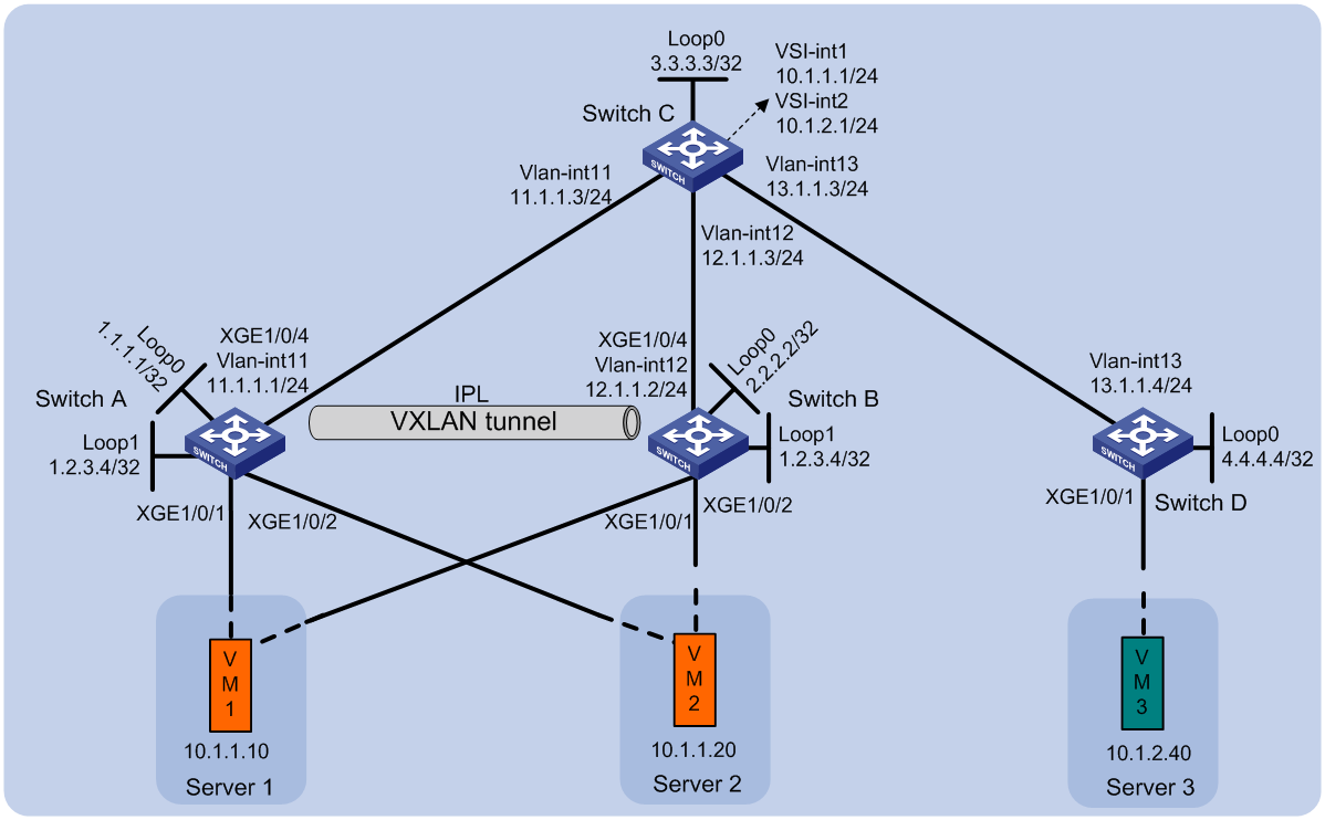
Procedure
1. Set the VXLAN hardware resource mode:
¡ (S6800 and S6860 switch series.) Set the VXLAN hardware resource mode on Switch C and reboot the switch for the mode to take effect.
<SwitchC> system-view
[SwitchC] hardware-resource vxlan l3gw16k
Do you want to change the specified hardware resource working mode? [Y/N]:y
The hardware resource working mode is changed, please save the configuration and
reboot the system to make it effective.
[SwitchC] quit
<SwitchC> reboot
Start to check configuration with next startup configuration file, please wait..
.......DONE!
Current configuration may be lost after the reboot, save current configuration?
[Y/N]:y
This command will reboot the device. Continue? [Y/N]:y
¡ (S6820 switch series.) Set the VXLAN hardware resource mode to l3gw or border on Switch C and reboot the switch for the mode to take effect. (Details not shown.)
2. On VM 1 and VM 2, specify 10.1.1.1 as the gateway address. On VM 3, specify 10.1.2.1 as the gateway address. (Details not shown.)
3. Configure IP addresses and unicast routing settings:
# Assign IP addresses to interfaces (including loopback interfaces), as shown in Figure 24. (Details not shown.)
# Configure OSPF on all transport network switches (Switches A through D) for them to reach one another. (Details not shown.)
4. Configure Switch A:
# Enable L2VPN.
<SwitchA> system-view
[SwitchA] l2vpn enable
# Disable remote MAC address learning and remote ARP learning.
[SwitchA] vxlan tunnel mac-learning disable
[SwitchA] vxlan tunnel arp-learning disable
# Enable EVPN distributed relay, and specify the virtual VTEP address as 1.2.3.4.
[SwitchA] evpn drni group 1.2.3.4
# Specify the reserved VXLAN as VXLAN 1234.
[SwitchA] reserved vxlan 1234
# Configure DR system parameters.
[SwitchA] drni system-mac 0001-0001-0001
[SwitchA] drni system-number 1
[SwitchA] drni system-priority 10
[SwitchA] drni keepalive ip destination 12.1.1.2 source 11.1.1.1
[SwitchA] drni restore-delay 180
# Create a tunnel to Switch B, and set the ToS of tunneled packets to 100.
[SwitchA] interface tunnel 1 mode vxlan
[SwitchA-Tunnel1] source 1.1.1.1
[SwitchA-Tunnel1] destination 2.2.2.2
[SwitchA-Tunnel1] tunnel tos 100
[SwitchA-Tunnel1] quit
# Exclude Tunnel 1 from the shutdown action by DRNI MAD.
[SwitchA] drni mad exclude interface tunnel 1
# Specify Tunnel 1 as the IPP
[SwitchA] interface tunnel 1
[SwitchA-Tunnel1] port drni intra-portal-port 1
[SwitchA-Tunnel1] quit
# Disable static source check and spanning tree on Ten-GigabitEthernet 1/0/4, the transport-facing outgoing interface for tunneled traffic.
[SwitchA] interface ten-gigabitethernet 1/0/4
[SwitchA-Ten-GigabitEthernet1/0/4] undo mac-address static source-check enable
[SwitchA-Ten-GigabitEthernet1/0/4] undo stp enable
[SwitchA-Ten-GigabitEthernet1/0/4] quit
# Create Layer 2 dynamic aggregate interface Bridge-Aggregation 4.
[SwitchA] interface bridge-aggregation 4
[SwitchA-Bridge-Aggregation4] link-aggregation mode dynamic
[SwitchA-Bridge-Aggregation4] quit
# Assign Ten-GigabitEthernet 1/0/1 to link aggregation group 4.
[SwitchA] interface ten-gigabitethernet 1/0/1
[SwitchA-Ten-GigabitEthernet1/0/1] port link-aggregation group 4
[SwitchA-Ten-GigabitEthernet1/0/1] quit
# Assign Bridge-Aggregation 4 to DR group 4.
[SwitchA] interface bridge-aggregation 4
[SwitchA-Bridge-Aggregation4] port drni group 4
[SwitchA-Bridge-Aggregation4] quit
# Create Layer 2 dynamic aggregate interface Bridge-Aggregation 5.
[SwitchA] interface bridge-aggregation 5
[SwitchA-Bridge-Aggregation5] link-aggregation mode dynamic
[SwitchA-Bridge-Aggregation5] quit
# Assign Ten-GigabitEthernet 1/0/2 to link aggregation group 5.
[SwitchA] interface ten-gigabitethernet 1/0/2
[SwitchA-Ten-GigabitEthernet1/0/2] port link-aggregation group 5
[SwitchA-Ten-GigabitEthernet1/0/2] quit
# Assign Bridge-Aggregation 5 to DR group 5.
[SwitchA] interface bridge-aggregation 5
[SwitchA-Bridge-Aggregation5] port drni group 5
[SwitchA-Bridge-Aggregation5] quit
# Create an EVPN instance on VSI vpna, and configure the switch to automatically generate an RD and a route target for the EVPN instance.
[SwitchA] vsi vpna
[SwitchA-vsi-vpna] arp suppression enable
[SwitchA-vsi-vpna] evpn encapsulation vxlan
[SwitchA-vsi-vpna-evpn-vxlan] route-distinguisher auto
[SwitchA-vsi-vpna-evpn-vxlan] vpn-target auto
[SwitchA-vsi-vpna-evpn-vxlan] quit
# Create VXLAN 10.
[SwitchA-vsi-vpna] vxlan 10
[SwitchA-vsi-vpna-vxlan-10] quit
[SwitchA-vsi-vpna] quit
# Configure BGP to advertise BGP EVPN routes.
[SwitchA] bgp 200
[SwitchA-bgp-default] peer 3.3.3.3 as-number 200
[SwitchA-bgp-default] peer 3.3.3.3 connect-interface loopback 0
[SwitchA-bgp-default] address-family l2vpn evpn
[SwitchA-bgp-default-evpn] peer 3.3.3.3 enable
[SwitchA-bgp-default-evpn] quit
[SwitchA-bgp-default] quit
# On Bridge-Aggregation 4, create Ethernet service instance 1000 to match VLAN 2.
[SwitchA] interface bridge-aggregation 4
[SwitchA-Bridge-Aggregation4] service-instance 1000
[SwitchA-Bridge-Aggregation4-srv1000] encapsulation s-vid 2
# Map Ethernet service instance 1000 to VSI vpna.
[SwitchA-Bridge-Aggregation4-srv1000] xconnect vsi vpna
[SwitchA-Bridge-Aggregation4-srv1000] quit
# On Bridge-Aggregation 5, create Ethernet service instance 1000 to match VLAN 3.
[SwitchA] interface bridge-aggregation 5
[SwitchA-Bridge-Aggregation5] service-instance 1000
[SwitchA-Bridge-Aggregation5-srv1000] encapsulation s-vid 3
# Map Ethernet service instance 1000 to VSI vpna.
[SwitchA-Bridge-Aggregation5-srv1000] xconnect vsi vpna
[SwitchA-Bridge-Aggregation5-srv1000] quit
# Exclude the interfaces used by EVPN from the shutdown action by DRNI MAD.
[SwitchA] drni mad exclude interface loopback 0
[SwitchA] drni mad exclude interface loopback 1
[SwitchA] drni mad exclude interface ten-gigabitethernet 1/0/4
[SwitchA] drni mad exclude interface vlan-interface 11
5. Configure Switch B:
# Enable L2VPN.
<SwitchB> system-view
[SwitchB] l2vpn enable
# Disable remote MAC address learning and remote ARP learning.
[SwitchB] vxlan tunnel mac-learning disable
[SwitchB] vxlan tunnel arp-learning disable
# Enable EVPN distributed relay, and specify the virtual VTEP address as 1.2.3.4.
[SwitchB] evpn drni group 1.2.3.4
# Specify the reserved VXLAN as VXLAN 1234.
[SwitchB] reserved vxlan 1234
# Configure DR system parameters.
[SwitchB] drni system-mac 0001-0001-0001
[SwitchB] drni system-number 2
[SwitchB] drni system-priority 10
[SwitchB] drni keepalive ip destination 11.1.1.1 source 12.1.1.2
[SwitchB] drni restore-delay 180
# Create a tunnel to Switch A, and set the ToS of tunneled packets to 100.
[SwitchB] interface tunnel 1 mode vxlan
[SwitchB-Tunnel1] source 2.2.2.2
[SwitchB-Tunnel1] destination 1.1.1.1
[SwitchB-Tunnel1] tunnel tos 100
[SwitchB-Tunnel1] quit
# Exclude Tunnel 1 from the shutdown action by DRNI MAD.
[SwitchB] drni mad exclude interface tunnel 1
# Specify Tunnel 1 as the IPP
[SwitchB] interface tunnel 1
[SwitchB-Tunnel1] port drni intra-portal-port 1
[SwitchB-Tunnel1] quit
# Disable static source check and spanning tree on Ten-GigabitEthernet 1/0/4, the transport-facing outgoing interface for tunneled traffic.
[SwitchB] interface ten-gigabitethernet 1/0/4
[SwitchB-Ten-GigabitEthernet1/0/4] undo mac-address static source-check enable
[SwitchB-Ten-GigabitEthernet1/0/4] undo stp enable
[SwitchB-Ten-GigabitEthernet1/0/4] quit
# Create Layer 2 dynamic aggregate interface Bridge-Aggregation 4.
[SwitchB] interface bridge-aggregation 4
[SwitchB-Bridge-Aggregation4] link-aggregation mode dynamic
[SwitchB-Bridge-Aggregation4] quit
# Assign Ten-GigabitEthernet 1/0/1 to aggregation group 4.
[SwitchB] interface ten-gigabitethernet 1/0/1
[SwitchB-Ten-GigabitEthernet1/0/1] port link-aggregation group 4
[SwitchB-Ten-GigabitEthernet1/0/1] quit
# Assign Bridge-Aggregation 4 to DR group 4.
[SwitchB] interface bridge-aggregation 4
[SwitchB-Bridge-Aggregation4] port drni group 4
[SwitchB-Bridge-Aggregation4] quit
# Create Layer 2 dynamic aggregate interface Bridge-Aggregation 5.
[SwitchB] interface bridge-aggregation 5
[SwitchB-Bridge-Aggregation5] link-aggregation mode dynamic
[SwitchB-Bridge-Aggregation5] quit
# Assign Ten-GigabitEthernet 1/0/2 to aggregation group 5.
[SwitchB] interface ten-gigabitethernet 1/0/2
[SwitchB-Ten-GigabitEthernet1/0/2] port link-aggregation group 5
[SwitchB-Ten-GigabitEthernet1/0/2] quit
# Assign Bridge-Aggregation 5 to DR group 5.
[SwitchB] interface bridge-aggregation 5
[SwitchB-Bridge-Aggregation5] port drni group 5
[SwitchB-Bridge-Aggregation5] quit
# Create an EVPN instance on VSI vpna, and configure the switch to automatically generate an RD and a route target for the EVPN instance.
[SwitchB] vsi vpna
[SwitchB-vsi-vpna] arp suppression enable
[SwitchB-vsi-vpna] evpn encapsulation vxlan
[SwitchB-vsi-vpna-evpn-vxlan] route-distinguisher auto
[SwitchB-vsi-vpna-evpn-vxlan] vpn-target auto
[SwitchB-vsi-vpna-evpn-vxlan] quit
# Create VXLAN 10.
[SwitchB-vsi-vpna] vxlan 10
[SwitchB-vsi-vpna-vxlan-10] quit
[SwitchB-vsi-vpna] quit
# Configure BGP to advertise BGP EVPN routes.
[SwitchB] bgp 200
[SwitchB-bgp-default] peer 3.3.3.3 as-number 200
[SwitchB-bgp-default] peer 3.3.3.3 connect-interface loopback 0
[SwitchB-bgp-default] address-family l2vpn evpn
[SwitchB-bgp-default-evpn] peer 3.3.3.3 enable
[SwitchB-bgp-default-evpn] quit
[SwitchB-bgp-default] quit
# On Bridge-Aggregation 4, create Ethernet service instance 1000 to match VLAN 2.
[SwitchB] interface bridge-aggregation 4
[SwitchB-Bridge-Aggregation4] service-instance 1000
[SwitchB-Bridge-Aggregation4-srv1000] encapsulation s-vid 2
# Map Ethernet service instance 1000 to VSI vpna.
[SwitchB-Bridge-Aggregation4-srv1000] xconnect vsi vpna
[SwitchB-Bridge-Aggregation4-srv1000] quit
# On Bridge-Aggregation 5, create Ethernet service instance 1000 to match VLAN 3.
[SwitchB] interface bridge-aggregation 5
[SwitchB-Bridge-Aggregation5] service-instance 1000
[SwitchB-Bridge-Aggregation5-srv1000] encapsulation s-vid 3
# Map Ethernet service instance 1000 to VSI vpna.
[SwitchB-Bridge-Aggregation5-srv1000] xconnect vsi vpna
[SwitchB-Bridge-Aggregation5-srv1000] quit
# Exclude the interfaces used by EVPN from the shutdown action by DRNI MAD.
[SwitchB] drni mad exclude interface loopback 0
[SwitchB] drni mad exclude interface loopback 1
[SwitchB] drni mad exclude interface ten-gigabitethernet 1/0/4
[SwitchB] drni mad exclude interface vlan-interface 11
6. Configure Switch C:
# Enable L2VPN.
<SwitchC> system-view
[SwitchC] l2vpn enable
# Reserve the global VLAN interface resources for VLANs 3000 and 3001.
[SwitchC] reserve-vlan-interface 3000 to 3001 global
# Create VSI gateway service loopback group 1, and assign Layer 2 Ethernet interface Ten-GigabitEthernet 1/0/4 to the service loopback group.
[SwitchC] service-loopback group 1 type vsi-gateway
[SwitchC] interface ten-gigabitethernet 1/0/4
[SwitchC-Ten-GigabitEthernet1/0/4] port service-loopback group 1
All configurations on the interface will be lost. Continue?[Y/N]:y
[SwitchA-Ten-GigabitEthernet1/0/4] quit
# Disable remote MAC address learning.
[SwitchC] vxlan tunnel mac-learning disable
# Create an EVPN instance on VSI vpna, and configure the switch to automatically generate an RD and a route target for the EVPN instance.
[SwitchC] vsi vpna
[SwitchC-vsi-vpna] evpn encapsulation vxlan
[SwitchC-vsi-vpna-evpn-vxlan] route-distinguisher auto
[SwitchC-vsi-vpna-evpn-vxlan] vpn-target auto
[SwitchC-vsi-vpna-evpn-vxlan] quit
# Create VXLAN 10.
[SwitchC-vsi-vpna] vxlan 10
[SwitchC-vsi-vpna-vxlan-10] quit
[SwitchC-vsi-vpna] quit
# Create an EVPN instance on VSI vpnb, and configure the switch to automatically generate an RD and a route target for the EVPN instance.
[SwitchC] vsi vpnb
[SwitchC-vsi-vpnb] evpn encapsulation vxlan
[SwitchC-vsi-vpnb-evpn-vxlan] route-distinguisher auto
[SwitchC-vsi-vpnb-evpn-vxlan] vpn-target auto
[SwitchC-vsi-vpnb-evpn-vxlan] quit
# Create VXLAN 20.
[SwitchC-vsi-vpnb] vxlan 20
[SwitchC-vsi-vpnb-vxlan-20] quit
[SwitchC-vsi-vpnb] quit
# Configure BGP to advertise BGP EVPN routes, and configure Switch C as an RR.
[SwitchC] bgp 200
[SwitchC-bgp-default] group evpn
[SwitchC-bgp-default] peer 1.1.1.1 group evpn
[SwitchC-bgp-default] peer 2.2.2.2 group evpn
[SwitchC-bgp-default] peer 4.4.4.4 group evpn
[SwitchC-bgp-default] peer evpn as-number 200
[SwitchC-bgp-default] peer evpn connect-interface loopback 0
[SwitchC-bgp-default] address-family l2vpn evpn
[SwitchC-bgp-default-evpn] peer evpn enable
[SwitchC-bgp-default-evpn] undo policy vpn-target
[SwitchC-bgp-default-evpn] peer evpn reflect-client
[SwitchC-bgp-default-evpn] quit
[SwitchC-bgp-default] quit
# Create VSI-interface 1 and assign it an IP address. The IP address is the gateway address of VXLAN 10.
[SwitchC] interface vsi-interface 1
[SwitchC-Vsi-interface1] ip address 10.1.1.1 255.255.255.0
[SwitchC-Vsi-interface1] quit
# Specify VSI-interface 1 as the gateway interface for VSI vpna.
[SwitchC] vsi vpna
[SwitchC-vsi-vpna] gateway vsi-interface 1
[SwitchC-vsi-vpna] quit
# Create VSI-interface 2 and assign it an IP address. The IP address is the gateway address of VXLAN 20.
[SwitchC] interface vsi-interface 2
[SwitchC-Vsi-interface2] ip address 10.1.2.1 255.255.255.0
[SwitchC-Vsi-interface2] quit
# Specify VSI-interface 2 as the gateway interface for VSI vpnb.
[SwitchC] vsi vpnb
[SwitchC-vsi-vpnb] gateway vsi-interface 2
[SwitchC-vsi-vpnb] quit
7. Configure Switch D:
# Enable L2VPN.
<SwitchD> system-view
[SwitchD] l2vpn enable
# Create an EVPN instance on VSI vpnb, and configure the switch to automatically generate an RD and a route target for the EVPN instance.
[SwitchD] vsi vpnb
[SwitchD-vsi-vpnb] arp suppression enable
[SwitchD-vsi-vpnb] evpn encapsulation vxlan
[SwitchD-vsi-vpnb-evpn-vxlan] route-distinguisher auto
[SwitchD-vsi-vpnb-evpn-vxlan] vpn-target auto
[SwitchD-vsi-vpnb-evpn-vxlan] quit
# Create VXLAN 20.
[SwitchD-vsi-vpnb] vxlan 20
[SwitchD-vsi-vpnb-vxlan-20] quit
[SwitchD-vsi-vpnb] quit
# Configure BGP to advertise BGP EVPN routes.
[SwitchD] bgp 200
[SwitchD-bgp-default] peer 3.3.3.3 as-number 200
[SwitchD-bgp-default] peer 3.3.3.3 connect-interface loopback 0
[SwitchD-bgp-default] address-family l2vpn evpn
[SwitchD-bgp-default-evpn] peer 3.3.3.3 enable
[SwitchD-bgp-default-evpn] quit
[SwitchD-bgp-default] quit
# On Ten-GigabitEthernet 1/0/1, create Ethernet service instance 1000 to match VLAN 4.
[SwitchD] interface ten-gigabitethernet 1/0/1
[SwitchD-Ten-GigabitEthernet1/0/1] service-instance 1000
[SwitchD-Ten-GigabitEthernet1/0/1] encapsulation s-vid 4
# Map Ethernet service instance 1000 to VSI vpnb.
[SwitchD-Ten-GigabitEthernet1/0/1] xconnect vsi vpnb
[SwitchD-Ten-GigabitEthernet1/0/1] quit
Verifying the configuration
1. Verify the centralized EVPN gateway settings on Switch C:
# Verify that Switch C has advertised MAC/IP advertisement routes and IMET routes of the gateway to other devices. Verify that Switch C has received MAC/IP advertisement routes and IMET routes from Switch A, Switch B, and Switch D.
[SwitchC] display bgp l2vpn evpn
BGP local router ID is 3.3.3.3
Status codes: * - valid, > - best, d - dampened, h - history,
s - suppressed, S - stale, i - internal, e - external
a - additional-path
Origin: i - IGP, e - EGP, ? - incomplete
Total number of routes from all PEs: 5
Route distinguisher: 1:10
Total number of routes: 6
* > [2][0][48][7e9a-48e9-0100][32][10.1.1.1]/136
NextHop : 0.0.0.0 LocPrf : 100
PrefVal : 32768 OutLabel : NULL
MED : 0
Path/Ogn: i
* i Network : [3][0][32][1.1.1.1]/80
NextHop : 1.1.1.1 LocPrf : 100
PrefVal : 0 OutLabel : NULL
MED : 0
Path/Ogn: i
* >i Network : [3][0][32][1.2.3.4]/80
NextHop : 1.2.3.4 LocPrf : 100
PrefVal : 0 OutLabel : NULL
MED : 0
Path/Ogn: i
* i Network : [3][0][32][1.2.3.4]/80
NextHop : 1.2.3.4 LocPrf : 100
PrefVal : 0 OutLabel : NULL
MED : 0
Path/Ogn: i
* >i Network : [3][0][32][2.2.2.2]/80
NextHop : 2.2.2.2 LocPrf : 100
PrefVal : 0 OutLabel : NULL
MED : 0
Path/Ogn: i
* > Network : [3][0][32][3.3.3.3]/80
NextHop : 0.0.0.0 LocPrf : 100
PrefVal : 32768 OutLabel : NULL
MED : 0
Path/Ogn: i
Route distinguisher: 1:20
Total number of routes: 3
* > Network : [2][0][48][7e9a-48e9-0100][32][10.1.2.1]/136
NextHop : 0.0.0.0 LocPrf : 100
PrefVal : 32768 OutLabel : NULL
MED : 0
Path/Ogn: i
* > Network : [3][0][32][3.3.3.3]/80
NextHop : 0.0.0.0 LocPrf : 100
PrefVal : 32768 OutLabel : NULL
MED : 0
Path/Ogn: i
* >i Network : [3][0][32][4.4.4.4]/80
NextHop : 4.4.4.4 LocPrf : 100
PrefVal : 0 OutLabel : NULL
MED : 0
Path/Ogn: i
# Verify that the VXLAN tunnels to Switch A and Switch B are up, and the device has established a VXLAN tunnel to Switch A and Switch B with the destination address as the virtual VTEP address.
[SwitchC] display interface tunnel
Tunnel0
Current state: UP
Line protocol state: UP
Description: Tunnel0 Interface
Bandwidth: 64 kbps
Maximum transmission unit: 1464
Internet protocol processing: Disabled
Last clearing of counters: Never
Tunnel source 3.3.3.3, destination 4.4.4.4
Tunnel protocol/transport UDP_VXLAN/IP
Last 300 seconds input rate: 0 bytes/sec, 0 bits/sec, 0 packets/sec
Last 300 seconds output rate: 0 bytes/sec, 0 bits/sec, 0 packets/sec
Input: 0 packets, 0 bytes, 0 drops
Output: 2 packets, 84 bytes, 0 drops
Tunnel1
Current state: UP
Line protocol state: UP
Description: Tunnel1 Interface
Bandwidth: 64 kbps
Maximum transmission unit: 1464
Internet protocol processing: Disabled
Last clearing of counters: Never
Tunnel source 3.3.3.3, destination 1.1.1.1
Tunnel protocol/transport UDP_VXLAN/IP
Last 300 seconds input rate: 0 bytes/sec, 0 bits/sec, 0 packets/sec
Last 300 seconds output rate: 0 bytes/sec, 0 bits/sec, 0 packets/sec
Input: 0 packets, 0 bytes, 0 drops
Output: 2 packets, 84 bytes, 0 drops
Tunnel2
Current state: UP
Line protocol state: UP
Description: Tunnel2 Interface
Bandwidth: 64 kbps
Maximum transmission unit: 1464
Internet protocol processing: Disabled
Last clearing of counters: Never
Tunnel source 3.3.3.3, destination 1.2.3.4
Tunnel protocol/transport UDP_VXLAN/IP
Last 300 seconds input rate: 0 bytes/sec, 0 bits/sec, 0 packets/sec
Last 300 seconds output rate: 0 bytes/sec, 0 bits/sec, 0 packets/sec
Input: 0 packets, 0 bytes, 0 drops
Output: 1 packets, 42 bytes, 0 drops
Tunnel3
Current state: UP
Line protocol state: UP
Description: Tunnel3 Interface
Bandwidth: 64 kbps
Maximum transmission unit: 1464
Internet protocol processing: Disabled
Last clearing of counters: Never
Tunnel source 3.3.3.3, destination 2.2.2.2
Tunnel protocol/transport UDP_VXLAN/IP
Last 300 seconds input rate: 0 bytes/sec, 0 bits/sec, 0 packets/sec
Last 300 seconds output rate: 0 bytes/sec, 0 bits/sec, 0 packets/sec
Input: 0 packets, 0 bytes, 0 drops
Output: 1 packets, 42 bytes, 0 drops
# Verify that the VXLAN tunnels have been assigned to the VXLANs, and that the VSI interfaces are the gateway interfaces of their respective VXLANs.
[SwitchC] display l2vpn vsi verbose
VSI Name: vpna
VSI Index : 0
VSI State : Up
MTU : 1500
Bandwidth : Unlimited
Broadcast Restrain : Unlimited
Multicast Restrain : Unlimited
Unknown Unicast Restrain: Unlimited
MAC Learning : Enabled
MAC Table Limit : -
MAC Learning rate : -
Drop Unknown : -
Flooding : Enabled
Statistics : Disabled
Gateway Interface : VSI-interface 1
VXLAN ID : 10
Tunnels:
Tunnel Name Link ID State Type Flood proxy
Tunnel1 0x5000001 UP Auto Disabled
Tunnel2 0x5000002 UP Auto Disabled
Tunnel3 0x5000003 UP Auto Disabled
VSI Name: vpnb
VSI Index : 1
VSI State : Up
MTU : 1500
Bandwidth : Unlimited
Broadcast Restrain : Unlimited
Multicast Restrain : Unlimited
Unknown Unicast Restrain: Unlimited
MAC Learning : Enabled
MAC Table Limit : -
MAC Learning rate : -
Drop Unknown : -
Flooding : Enabled
Statistics : Disabled
Gateway Interface : VSI-interface 2
VXLAN ID : 20
Tunnels:
Tunnel Name Link ID State Type Flood proxy
Tunnel0 0x5000000 UP Auto Disabled
2. Verify the distributed relay settings on Switch A:
# Verify that Switch A has BGP EVPN routes.
[SwitchA] display bgp l2vpn evpn
BGP local router ID is 1.2.3.4
Status codes: * - valid, > - best, d - dampened, h - history,
s - suppressed, S - stale, i - internal, e - external
a - additional-path
Origin: i - IGP, e - EGP, ? - incomplete
Total number of routes from all PEs: 3
Route distinguisher: 1:10
Total number of routes: 5
* >i Network : [2][0][48][7e9a-48e9-0100][32][10.1.1.1]/136
NextHop : 3.3.3.3 LocPrf : 100
PrefVal : 0 OutLabel : NULL
MED : 0
Path/Ogn: i
* > Network : [3][0][32][1.1.1.1]/80
NextHop : 1.1.1.1 LocPrf : 100
PrefVal : 32768 OutLabel : NULL
MED : 0
Path/Ogn: i
* > Network : [3][0][32][1.2.3.4]/80
NextHop : 1.2.3.4 LocPrf : 100
PrefVal : 32768 OutLabel : NULL
MED : 0
Path/Ogn: i
* >i Network : [3][0][32][3.3.3.3]/80
NextHop : 3.3.3.3 LocPrf : 100
PrefVal : 0 OutLabel : NULL
MED : 0
Path/Ogn: i
* >i Network : [3][0][32][2.2.2.2]/80
NextHop : 2.2.2.2 LocPrf : 100
PrefVal : 0 OutLabel : NULL
MED : 0
Path/Ogn: i
# Verify that the VXLAN tunnel to Switch C is up, and the tunnel source address is the virtual VTEP address.
[SwitchA] display interface tunnel
Tunnel0
Current state: UP
Line protocol state: UP
Description: Tunnel0 Interface
Bandwidth: 64 kbps
Maximum transmission unit: 1464
Internet protocol processing: Disabled
Last clearing of counters: Never
Tunnel source 1.2.3.4, destination 3.3.3.3
Tunnel protocol/transport UDP_VXLAN/IP
Last 300 seconds input rate: 0 bytes/sec, 0 bits/sec, 0 packets/sec
Last 300 seconds output rate: 0 bytes/sec, 0 bits/sec, 0 packets/sec
Input: 0 packets, 0 bytes, 0 drops
Output: 0 packets, 0 bytes, 0 drops
Tunnel1
Current state: UP
Line protocol state: UP
Description: Tunnel1 Interface
Bandwidth: 64 kbps
Maximum transmission unit: 1464
Internet protocol processing: Disabled
Last clearing of counters: Never
Tunnel source 1.1.1.1, destination 2.2.2.2
Tunnel protocol/transport UDP_VXLAN/IP
Last 300 seconds input rate: 12 bytes/sec, 96 bits/sec, 0 packets/sec
Last 300 seconds output rate: 12 bytes/sec, 96 bits/sec, 0 packets/sec
Input: 239 packets, 25558 bytes, 0 drops
Output: 1241 packets, 109811 bytes, 0 drops
# Verify that ACs are automatically created on the IPL and assigned to VSIs.
[SwitchA] display l2vpn vsi verbose
VSI Name: vpna
VSI Index : 0
VSI State : Up
MTU : 1500
Bandwidth : Unlimited
Broadcast Restrain : Unlimited
Multicast Restrain : Unlimited
Unknown Unicast Restrain: Unlimited
MAC Learning : Enabled
MAC Table Limit : -
MAC Learning rate : -
Drop Unknown : -
Flooding : Enabled
Statistics : Disabled
VXLAN ID : 10
Tunnels:
Tunnel Name Link ID State Type Flood proxy
Tunnel0 0x5000000 UP Auto Disabled
Tunnel1 0x5000001 UP Manual Disabled
ACs:
AC Link ID State Type
BAGG4 srv1000 0 Down Manual
BAGG5 srv1000 1 Down Manual
3. Verify network connectivity for the VMs:
# Verify that VM 1, VM 2, and VM 3 can communicate when both Switch A and Switch B are operating correctly. (Details not shown.)
# Verify that VM 1, VM 2, and VM 3 can communicate when Switch A's or Switch B's links to the local site are disconnected. (Details not shown.)
Example: Configuring IPv4 EVPN distributed relay using a VXLAN tunnel as the IPL (with Monitor Link)
Network configuration
As shown in Figure 25, perform the following tasks to make sure the VMs can communicate with one another:
· Configure VXLAN 10 on Switch A, Switch B, and Switch C, and configure VXLAN 20 on Switch C and Switch D.
· Configure EVPN distributed relay on Switch A and Switch B to virtualize them into one VTEP. The switches use a VXLAN tunnel as the IPL.
· Create a monitor link group on Switch A and Switch B. Configure the transport-facing interfaces of Switch A and Switch B as uplink interfaces for the monitor link group, and member interfaces of DR interfaces as downlink interfaces.
· Configure Switch C as a centralized EVPN gateway and RR.

Procedure
1. Set the VXLAN hardware resource mode:
¡ (S6800 and S6860 switch series.) Set the VXLAN hardware resource mode on Switch C and reboot the switch for the mode to take effect.
<SwitchC> system-view
[SwitchC] hardware-resource vxlan l3gw16k
Do you want to change the specified hardware resource working mode? [Y/N]:y
The hardware resource working mode is changed, please save the configuration and
reboot the system to make it effective.
[SwitchC] quit
<SwitchC> reboot
Start to check configuration with next startup configuration file, please wait..
.......DONE!
Current configuration may be lost after the reboot, save current configuration?
[Y/N]:y
This command will reboot the device. Continue? [Y/N]:y
¡ (S6820 switch series.) Set the VXLAN hardware resource mode to l3gw or border on Switch C and reboot the switch for the mode to take effect. (Details not shown.)
2. On VM 1 and VM 2, specify 10.1.1.1 as the gateway address. On VM 3, specify 10.1.2.1 as the gateway address. (Details not shown.)
3. Configure IP addresses and unicast routing settings:
# Assign IP addresses to interfaces (including loopback interfaces), as shown in Figure 25. (Details not shown.)
# Configure OSPF on all transport network switches (Switches A through D) for them to reach one another. (Details not shown.)
4. Configure Switch A:
# Enable L2VPN.
<SwitchA> system-view
[SwitchA] l2vpn enable
# Disable remote MAC address learning and remote ARP learning.
[SwitchA] vxlan tunnel mac-learning disable
[SwitchA] vxlan tunnel arp-learning disable
# Enable EVPN distributed relay, and specify the virtual VTEP address as 1.2.3.4.
[SwitchA] evpn drni group 1.2.3.4
# Specify the reserved VXLAN as VXLAN 1234.
[SwitchA] reserved vxlan 1234
# Configure DR system parameters.
[SwitchA] drni system-mac 0001-0001-0001
[SwitchA] drni system-number 1
[SwitchA] drni system-priority 10
[SwitchA] drni keepalive ip destination 12.1.1.2 source 11.1.1.1
[SwitchA] drni restore-delay 180
# Create a tunnel to Switch B, and set the ToS of tunneled packets to 100.
[SwitchA] interface tunnel 1 mode vxlan
[SwitchA-Tunnel1] source 1.1.1.1
[SwitchA-Tunnel1] destination 2.2.2.2
[SwitchA-Tunnel1] tunnel tos 100
[SwitchA-Tunnel1] quit
# Exclude Tunnel 1 from the shutdown action by DRNI MAD.
[SwitchA] drni mad exclude interface tunnel 1
# Specify Tunnel 1 as the IPP
[SwitchA] interface tunnel 1
[SwitchA-Tunnel1] port drni intra-portal-port 1
[SwitchA-Tunnel1] quit
# Disable static source check and spanning tree on Ten-GigabitEthernet 1/0/4, the transport-facing outgoing interface for tunneled traffic.
[SwitchA] interface ten-gigabitethernet 1/0/4
[SwitchA-Ten-GigabitEthernet1/0/4] undo mac-address static source-check enable
[SwitchA-Ten-GigabitEthernet1/0/4] undo stp enable
[SwitchA-Ten-GigabitEthernet1/0/4] quit
# Create Layer 2 dynamic aggregate interface Bridge-Aggregation 4.
[SwitchA] interface bridge-aggregation 4
[SwitchA-Bridge-Aggregation4] link-aggregation mode dynamic
[SwitchA-Bridge-Aggregation4] quit
# Assign Ten-GigabitEthernet 1/0/1 to link aggregation group 4.
[SwitchA] interface ten-gigabitethernet 1/0/1
[SwitchA-Ten-GigabitEthernet1/0/1] port link-aggregation group 4
[SwitchA-Ten-GigabitEthernet1/0/1] quit
# Assign Bridge-Aggregation 4 to DR group 4.
[SwitchA] interface bridge-aggregation 4
[SwitchA-Bridge-Aggregation4] port drni group 4
[SwitchA-Bridge-Aggregation4] quit
# Create Layer 2 dynamic aggregate interface Bridge-Aggregation 5.
[SwitchA] interface bridge-aggregation 5
[SwitchA-Bridge-Aggregation5] link-aggregation mode dynamic
[SwitchA-Bridge-Aggregation5] quit
# Assign Ten-GigabitEthernet 1/0/2 to link aggregation group 5.
[SwitchA] interface ten-gigabitethernet 1/0/2
[SwitchA-Ten-GigabitEthernet1/0/2] port link-aggregation group 5
[SwitchA-Ten-GigabitEthernet1/0/2] quit
# Assign Bridge-Aggregation 5 to DR group 5.
[SwitchA] interface bridge-aggregation 5
[SwitchA-Bridge-Aggregation5] port drni group 5
[SwitchA-Bridge-Aggregation5] quit
# Create an EVPN instance on VSI vpna, and configure the switch to automatically generate an RD and a route target for the EVPN instance.
[SwitchA] vsi vpna
[SwitchA-vsi-vpna] arp suppression enable
[SwitchA-vsi-vpna] evpn encapsulation vxlan
[SwitchA-vsi-vpna-evpn-vxlan] route-distinguisher auto
[SwitchA-vsi-vpna-evpn-vxlan] vpn-target auto
[SwitchA-vsi-vpna-evpn-vxlan] quit
# Create VXLAN 10.
[SwitchA-vsi-vpna] vxlan 10
[SwitchA-vsi-vpna-vxlan-10] quit
[SwitchA-vsi-vpna] quit
# Configure BGP to advertise BGP EVPN routes.
[SwitchA] bgp 200
[SwitchA-bgp-default] peer 3.3.3.3 as-number 200
[SwitchA-bgp-default] peer 3.3.3.3 connect-interface loopback 0
[SwitchA-bgp-default] address-family l2vpn evpn
[SwitchA-bgp-default-evpn] peer 3.3.3.3 enable
[SwitchA-bgp-default-evpn] quit
[SwitchA-bgp-default] quit
# On Bridge-Aggregation 4, create Ethernet service instance 1000 to match VLAN 2.
[SwitchA] interface bridge-aggregation 4
[SwitchA-Bridge-Aggregation4] service-instance 1000
[SwitchA-Bridge-Aggregation4-srv1000] encapsulation s-vid 2
# Map Ethernet service instance 1000 to VSI vpna.
[SwitchA-Bridge-Aggregation4-srv1000] xconnect vsi vpna
[SwitchA-Bridge-Aggregation4-srv1000] quit
# On Bridge-Aggregation 5, create Ethernet service instance 1000 to match VLAN 3.
[SwitchA] interface bridge-aggregation 5
[SwitchA-Bridge-Aggregation5] service-instance 1000
[SwitchA-Bridge-Aggregation5-srv1000] encapsulation s-vid 3
# Map Ethernet service instance 1000 to VSI vpna.
[SwitchA-Bridge-Aggregation5-srv1000] xconnect vsi vpna
[SwitchA-Bridge-Aggregation5-srv1000] quit
[SwitchA-Bridge-Aggregation5] quit
# Create monitor link group 1 and assign uplink and downlink interfaces to it.
[SwitchA] monitor-link group 1
[SwitchA-mtlk-group1] port ten-gigabitethernet 1/0/1 downlink
[SwitchA-mtlk-group1] port ten-gigabitethernet 1/0/2 downlink
[SwitchA-mtlk-group1] port ten-gigabitethernet 1/0/4 uplink
[SwitchA-mtlk-group1] quit
# Exclude the interfaces used by EVPN from the shutdown action by DRNI MAD.
[SwitchA] drni mad exclude interface loopback 0
[SwitchA] drni mad exclude interface loopback 1
[SwitchA] drni mad exclude interface ten-gigabitethernet 1/0/4
[SwitchA] drni mad exclude interface vlan-interface 11
5. Configure Switch B:
# Enable L2VPN.
<SwitchB> system-view
[SwitchB] l2vpn enable
# Disable remote MAC address learning and remote ARP learning.
[SwitchB] vxlan tunnel mac-learning disable
[SwitchB] vxlan tunnel arp-learning disable
# Enable EVPN distributed relay, and specify the virtual VTEP address as 1.2.3.4.
[SwitchB] evpn drni group 1.2.3.4
# Specify the reserved VXLAN as VXLAN 1234.
[SwitchB] reserved vxlan 1234
# Configure DR system parameters.
[SwitchB] drni system-mac 0001-0001-0001
[SwitchB] drni system-number 2
[SwitchB] drni system-priority 10
[SwitchB] drni keepalive ip destination 11.1.1.1 source 12.1.1.2
[SwitchB] drni restore-delay 180
# Create a tunnel to Switch A, and set the ToS of tunneled packets to 100.
[SwitchB] interface tunnel 1 mode vxlan
[SwitchB-Tunnel1] source 2.2.2.2
[SwitchB-Tunnel1] destination 1.1.1.1
[SwitchB-Tunnel1] tunnel tos 100
[SwitchB-Tunnel1] quit
# Exclude Tunnel 1 from the shutdown action by DRNI MAD.
[SwitchB] drni mad exclude interface tunnel 1
# Specify Tunnel 1 as the IPP
[SwitchB] interface tunnel 1
[SwitchB-Tunnel1] port drni intra-portal-port 1
[SwitchB-Tunnel1] quit
# Disable static source check and spanning tree on Ten-GigabitEthernet 1/0/4, the transport-facing outgoing interface for tunneled traffic.
[SwitchB] interface ten-gigabitethernet 1/0/4
[SwitchB-Ten-GigabitEthernet1/0/4] undo mac-address static source-check enable
[SwitchB-Ten-GigabitEthernet1/0/4] undo stp enable
[SwitchB-Ten-GigabitEthernet1/0/4] quit
# Create Layer 2 dynamic aggregate interface Bridge-Aggregation 4.
[SwitchB] interface bridge-aggregation 4
[SwitchB-Bridge-Aggregation4] link-aggregation mode dynamic
[SwitchB-Bridge-Aggregation4] quit
# Assign Ten-GigabitEthernet 1/0/1 to aggregation group 4.
[SwitchB] interface ten-gigabitethernet 1/0/1
[SwitchB-Ten-GigabitEthernet1/0/1] port link-aggregation group 4
[SwitchB-Ten-GigabitEthernet1/0/1] quit
# Assign Bridge-Aggregation 4 to DR group 4.
[SwitchB] interface bridge-aggregation 4
[SwitchB-Bridge-Aggregation4] port drni group 4
[SwitchB-Bridge-Aggregation4] quit
# Create Layer 2 dynamic aggregate interface Bridge-Aggregation 5.
[SwitchB] interface bridge-aggregation 5
[SwitchB-Bridge-Aggregation5] link-aggregation mode dynamic
[SwitchB-Bridge-Aggregation5] quit
# Assign Ten-GigabitEthernet 1/0/2 to aggregation group 5.
[SwitchB] interface ten-gigabitethernet 1/0/2
[SwitchB-Ten-GigabitEthernet1/0/2] port link-aggregation group 5
[SwitchB-Ten-GigabitEthernet1/0/2] quit
# Assign Bridge-Aggregation 5 to DR group 5.
[SwitchB] interface bridge-aggregation 5
[SwitchB-Bridge-Aggregation5] port drni group 5
[SwitchB-Bridge-Aggregation5] quit
# Create an EVPN instance on VSI vpna, and configure the switch to automatically generate an RD and a route target for the EVPN instance.
[SwitchB] vsi vpna
[SwitchB-vsi-vpna] arp suppression enable
[SwitchB-vsi-vpna] evpn encapsulation vxlan
[SwitchB-vsi-vpna-evpn-vxlan] route-distinguisher auto
[SwitchB-vsi-vpna-evpn-vxlan] vpn-target auto
[SwitchB-vsi-vpna-evpn-vxlan] quit
# Create VXLAN 10.
[SwitchB-vsi-vpna] vxlan 10
[SwitchB-vsi-vpna-vxlan-10] quit
[SwitchB-vsi-vpna] quit
# Configure BGP to advertise BGP EVPN routes.
[SwitchB] bgp 200
[SwitchB-bgp-default] peer 3.3.3.3 as-number 200
[SwitchB-bgp-default] peer 3.3.3.3 connect-interface loopback 0
[SwitchB-bgp-default] address-family l2vpn evpn
[SwitchB-bgp-default-evpn] peer 3.3.3.3 enable
[SwitchB-bgp-default-evpn] quit
[SwitchB-bgp-default] quit
# On Bridge-Aggregation 4, create Ethernet service instance 1000 to match VLAN 2.
[SwitchB] interface bridge-aggregation 4
[SwitchB-Bridge-Aggregation4] service-instance 1000
[SwitchB-Bridge-Aggregation4-srv1000] encapsulation s-vid 2
# Map Ethernet service instance 1000 to VSI vpna.
[SwitchB-Bridge-Aggregation4-srv1000] xconnect vsi vpna
[SwitchB-Bridge-Aggregation4-srv1000] quit
# On Bridge-Aggregation 5, create Ethernet service instance 1000 to match VLAN 3.
[SwitchB] interface bridge-aggregation 5
[SwitchB-Bridge-Aggregation5] service-instance 1000
[SwitchB-Bridge-Aggregation5-srv1000] encapsulation s-vid 3
# Map Ethernet service instance 1000 to VSI vpna.
[SwitchB-Bridge-Aggregation5-srv1000] xconnect vsi vpna
[SwitchB-Bridge-Aggregation5-srv1000] quit
[SwitchB-Bridge-Aggregation5] quit
# Create monitor link group 1 and assign uplink and downlink interfaces to it.
[SwitchB] monitor-link group 1
[SwitchB-mtlk-group1] port ten-gigabitethernet 1/0/1 downlink
[SwitchB-mtlk-group1] port ten-gigabitethernet 1/0/2 downlink
[SwitchB-mtlk-group1] port ten-gigabitethernet 1/0/4 uplink
[SwitchB-mtlk-group1] quit
# Exclude the interfaces used by EVPN from the shutdown action by DRNI MAD.
[SwitchB] drni mad exclude interface loopback 0
[SwitchB] drni mad exclude interface loopback 1
[SwitchB] drni mad exclude interface ten-gigabitethernet 1/0/4
[SwitchB] drni mad exclude interface vlan-interface 11
6. Configure Switch C:
# Enable L2VPN.
<SwitchC> system-view
[SwitchC] l2vpn enable
# Reserve the global VLAN interface resources of VLAN 3000 and VLAN 3001.
[SwitchC] reserve-vlan-interface 3000 to 3001 global
# Create VSI gateway service loopback group 1, and assign Layer 2 Ethernet interface Ten-GigabitEthernet 1/0/4 to the service loopback group.
[SwitchC] service-loopback group 1 type vsi-gateway
[SwitchC] interface ten-gigabitethernet 1/0/4
[SwitchC-Ten-GigabitEthernet1/0/4] port service-loopback group 1
All configurations on the interface will be lost. Continue?[Y/N]:y
[SwitchC-Ten-GigabitEthernet1/0/4] quit
# Disable remote MAC address learning.
[SwitchC] vxlan tunnel mac-learning disable
# Create an EVPN instance on VSI vpna, and configure the switch to automatically generate an RD and a route target for the EVPN instance.
[SwitchC] vsi vpna
[SwitchC-vsi-vpna] evpn encapsulation vxlan
[SwitchC-vsi-vpna-evpn-vxlan] route-distinguisher auto
[SwitchC-vsi-vpna-evpn-vxlan] vpn-target auto
[SwitchC-vsi-vpna-evpn-vxlan] quit
# Create VXLAN 10.
[SwitchC-vsi-vpna] vxlan 10
[SwitchC-vsi-vpna-vxlan-10] quit
[SwitchC-vsi-vpna] quit
# Create an EVPN instance on VSI vpnb, and configure the switch to automatically generate an RD and a route target for the EVPN instance.
[SwitchC] vsi vpnb
[SwitchC-vsi-vpnb] evpn encapsulation vxlan
[SwitchC-vsi-vpnb-evpn-vxlan] route-distinguisher auto
[SwitchC-vsi-vpnb-evpn-vxlan] vpn-target auto
[SwitchC-vsi-vpnb-evpn-vxlan] quit
# Create VXLAN 20.
[SwitchC-vsi-vpnb] vxlan 20
[SwitchC-vsi-vpnb-vxlan-20] quit
[SwitchC-vsi-vpnb] quit
# Configure BGP to advertise BGP EVPN routes, and configure Switch C as an RR.
[SwitchC] bgp 200
[SwitchC-bgp-default] group evpn
[SwitchC-bgp-default] peer 1.1.1.1 group evpn
[SwitchC-bgp-default] peer 2.2.2.2 group evpn
[SwitchC-bgp-default] peer 4.4.4.4 group evpn
[SwitchC-bgp-default] peer evpn as-number 200
[SwitchC-bgp-default] peer evpn connect-interface loopback 0
[SwitchC-bgp-default] address-family l2vpn evpn
[SwitchC-bgp-default-evpn] peer evpn enable
[SwitchC-bgp-default-evpn] undo policy vpn-target
[SwitchC-bgp-default-evpn] peer evpn reflect-client
[SwitchC-bgp-default-evpn] quit
[SwitchC-bgp-default] quit
# Create VSI-interface 1 and assign it an IP address. The IP address is the gateway address of VXLAN 10.
[SwitchC] interface vsi-interface 1
[SwitchC-Vsi-interface1] ip address 10.1.1.1 255.255.255.0
[SwitchC-Vsi-interface1] quit
# Specify VSI-interface 1 as the gateway interface for VSI vpna.
[SwitchC] vsi vpna
[SwitchC-vsi-vpna] gateway vsi-interface 1
[SwitchC-vsi-vpna] quit
# Create VSI-interface 2 and assign it an IP address. The IP address is the gateway address of VXLAN 20.
[SwitchC] interface vsi-interface 2
[SwitchC-Vsi-interface2] ip address 10.1.2.1 255.255.255.0
[SwitchC-Vsi-interface2] quit
# Specify VSI-interface 2 as the gateway interface for VSI vpnb.
[SwitchC] vsi vpnb
[SwitchC-vsi-vpnb] gateway vsi-interface 2
[SwitchC-vsi-vpnb] quit
7. Configure Switch D:
# Enable L2VPN.
<SwitchD> system-view
[SwitchD] l2vpn enable
# Create an EVPN instance on VSI vpnb, and configure the switch to automatically generate an RD and a route target for the EVPN instance.
[SwitchD] vsi vpnb
[SwitchD-vsi-vpnb] arp suppression enable
[SwitchD-vsi-vpnb] evpn encapsulation vxlan
[SwitchD-vsi-vpnb-evpn-vxlan] route-distinguisher auto
[SwitchD-vsi-vpnb-evpn-vxlan] vpn-target auto
[SwitchD-vsi-vpnb-evpn-vxlan] quit
# Create VXLAN 20.
[SwitchD-vsi-vpnb] vxlan 20
[SwitchD-vsi-vpnb-vxlan-20] quit
[SwitchD-vsi-vpnb] quit
# Configure BGP to advertise BGP EVPN routes.
[SwitchD] bgp 200
[SwitchD-bgp-default] peer 3.3.3.3 as-number 200
[SwitchD-bgp-default] peer 3.3.3.3 connect-interface loopback 0
[SwitchD-bgp-default] address-family l2vpn evpn
[SwitchD-bgp-default-evpn] peer 3.3.3.3 enable
[SwitchD-bgp-default-evpn] quit
[SwitchD-bgp-default] quit
# On Ten-GigabitEthernet 1/0/1, create Ethernet service instance 1000 to match VLAN 4.
[SwitchD] interface ten-gigabitethernet 1/0/1
[SwitchD-Ten-GigabitEthernet1/0/1] service-instance 1000
[SwitchD-Ten-GigabitEthernet1/0/1] encapsulation s-vid 4
# Map Ethernet service instance 1000 to VSI vpnb.
[SwitchD-Ten-GigabitEthernet1/0/1] xconnect vsi vpnb
[SwitchD-Ten-GigabitEthernet1/0/1] quit
Verifying the configuration
1. Verify the centralized EVPN gateway settings on Switch C:
# Verify that Switch C has advertised MAC/IP advertisement routes and IMET routes of the gateway to other devices. Verify that Switch C has received MAC/IP advertisement routes and IMET routes from Switch A, Switch B, and Switch D.
[SwitchC] display bgp l2vpn evpn
BGP local router ID is 3.3.3.3
Status codes: * - valid, > - best, d - dampened, h - history,
s - suppressed, S - stale, i - internal, e - external
a - additional-path
Origin: i - IGP, e - EGP, ? - incomplete
Total number of routes from all PEs: 5
Route distinguisher: 1:10
Total number of routes: 6
* > [2][0][48][7e9a-48e9-0100][32][10.1.1.1]/136
NextHop : 0.0.0.0 LocPrf : 100
PrefVal : 32768 OutLabel : NULL
MED : 0
Path/Ogn: i
* i Network : [3][0][32][1.1.1.1]/80
NextHop : 1.1.1.1 LocPrf : 100
PrefVal : 0 OutLabel : NULL
MED : 0
Path/Ogn: i
* >i Network : [3][0][32][1.2.3.4]/80
NextHop : 1.2.3.4 LocPrf : 100
PrefVal : 0 OutLabel : NULL
MED : 0
Path/Ogn: i
* i Network : [3][0][32][1.2.3.4]/80
NextHop : 1.2.3.4 LocPrf : 100
PrefVal : 0 OutLabel : NULL
MED : 0
Path/Ogn: i
* >i Network : [3][0][32][2.2.2.2]/80
NextHop : 2.2.2.2 LocPrf : 100
PrefVal : 0 OutLabel : NULL
MED : 0
Path/Ogn: i
* > Network : [3][0][32][3.3.3.3]/80
NextHop : 0.0.0.0 LocPrf : 100
PrefVal : 32768 OutLabel : NULL
MED : 0
Path/Ogn: i
Route distinguisher: 1:20
Total number of routes: 3
* > Network : [2][0][48][7e9a-48e9-0100][32][10.1.2.1]/136
NextHop : 0.0.0.0 LocPrf : 100
PrefVal : 32768 OutLabel : NULL
MED : 0
Path/Ogn: i
* > Network : [3][0][32][3.3.3.3]/80
NextHop : 0.0.0.0 LocPrf : 100
PrefVal : 32768 OutLabel : NULL
MED : 0
Path/Ogn: i
* >i Network : [3][0][32][4.4.4.4]/80
NextHop : 4.4.4.4 LocPrf : 100
PrefVal : 0 OutLabel : NULL
MED : 0
Path/Ogn: i
# Verify that the VXLAN tunnels to Switch A and Switch B are up, and the device has established a VXLAN tunnel to Switch A and Switch B with the destination address as the virtual VTEP address.
[SwitchC] display interface tunnel
Tunnel0
Current state: UP
Line protocol state: UP
Description: Tunnel0 Interface
Bandwidth: 64 kbps
Maximum transmission unit: 1464
Internet protocol processing: Disabled
Last clearing of counters: Never
Tunnel source 3.3.3.3, destination 4.4.4.4
Tunnel protocol/transport UDP_VXLAN/IP
Last 300 seconds input rate: 0 bytes/sec, 0 bits/sec, 0 packets/sec
Last 300 seconds output rate: 0 bytes/sec, 0 bits/sec, 0 packets/sec
Input: 0 packets, 0 bytes, 0 drops
Output: 0 packets, 0 bytes, 0 drops
Tunnel1
Current state: UP
Line protocol state: UP
Description: Tunnel1 Interface
Bandwidth: 64 kbps
Maximum transmission unit: 1464
Internet protocol processing: Disabled
Last clearing of counters: Never
Tunnel source 3.3.3.3, destination 1.1.1.1
Tunnel protocol/transport UDP_VXLAN/IP
Last 300 seconds input rate: 0 bytes/sec, 0 bits/sec, 0 packets/sec
Last 300 seconds output rate: 0 bytes/sec, 0 bits/sec, 0 packets/sec
Input: 0 packets, 0 bytes, 0 drops
Output: 0 packets, 0 bytes, 0 drops
Tunnel2
Current state: UP
Line protocol state: UP
Description: Tunnel2 Interface
Bandwidth: 64 kbps
Maximum transmission unit: 1464
Internet protocol processing: Disabled
Last clearing of counters: Never
Tunnel source 3.3.3.3, destination 1.2.3.4
Tunnel protocol/transport UDP_VXLAN/IP
Last 300 seconds input rate: 0 bytes/sec, 0 bits/sec, 0 packets/sec
Last 300 seconds output rate: 0 bytes/sec, 0 bits/sec, 0 packets/sec
Input: 0 packets, 0 bytes, 0 drops
Output: 0 packets, 0 bytes, 0 drops
Tunnel3
Current state: UP
Line protocol state: UP
Description: Tunnel3 Interface
Bandwidth: 64 kbps
Maximum transmission unit: 1464
Internet protocol processing: Disabled
Last clearing of counters: Never
Tunnel source 3.3.3.3, destination 2.2.2.2
Tunnel protocol/transport UDP_VXLAN/IP
Last 300 seconds input rate: 0 bytes/sec, 0 bits/sec, 0 packets/sec
Last 300 seconds output rate: 0 bytes/sec, 0 bits/sec, 0 packets/sec
Input: 0 packets, 0 bytes, 0 drops
Output: 0 packets, 0 bytes, 0 drops
# Verify that the VXLAN tunnels have been assigned to the VXLANs, and that the VSI interfaces are the gateway interfaces of their respective VXLANs.
[SwitchC] display l2vpn vsi verbose
VSI Name: vpna
VSI Index : 0
VSI State : Up
MTU : 1500
Bandwidth : Unlimited
Broadcast Restrain : Unlimited
Multicast Restrain : Unlimited
Unknown Unicast Restrain: Unlimited
MAC Learning : Enabled
MAC Table Limit : -
MAC Learning rate : -
Drop Unknown : -
Flooding : Enabled
Statistics : Disabled
Gateway Interface : VSI-interface 1
VXLAN ID : 10
Tunnels:
Tunnel Name Link ID State Type Flood proxy
Tunnel1 0x5000001 UP Auto Disabled
Tunnel2 0x5000002 UP Auto Disabled
Tunnel3 0x5000003 UP Auto Disabled
VSI Name: vpnb
VSI Index : 1
VSI State : Up
MTU : 1500
Bandwidth : Unlimited
Broadcast Restrain : Unlimited
Multicast Restrain : Unlimited
Unknown Unicast Restrain: Unlimited
MAC Learning : Enabled
MAC Table Limit : -
MAC Learning rate : -
Drop Unknown : -
Flooding : Enabled
Statistics : Disabled
Gateway Interface : VSI-interface 2
VXLAN ID : 20
Tunnels:
Tunnel Name Link ID State Type Flood proxy
Tunnel0 0x5000000 UP Auto Disabled
2. Verify the distributed relay settings on Switch A:
# Verify that Switch A has BGP EVPN routes.
[SwitchA] display bgp l2vpn evpn
BGP local router ID is 1.2.3.4
Status codes: * - valid, > - best, d - dampened, h - history,
s - suppressed, S - stale, i - internal, e - external
a - additional-path
Origin: i - IGP, e - EGP, ? - incomplete
Total number of routes from all PEs: 3
Route distinguisher: 1:10
Total number of routes: 5
* >i Network : [2][0][48][7e9a-48e9-0100][32][10.1.1.1]/136
NextHop : 3.3.3.3 LocPrf : 100
PrefVal : 0 OutLabel : NULL
MED : 0
Path/Ogn: i
* > Network : [3][0][32][1.1.1.1]/80
NextHop : 1.1.1.1 LocPrf : 100
PrefVal : 32768 OutLabel : NULL
MED : 0
Path/Ogn: i
* > Network : [3][0][32][1.2.3.4]/80
NextHop : 1.2.3.4 LocPrf : 100
PrefVal : 32768 OutLabel : NULL
MED : 0
Path/Ogn: i
* >i Network : [3][0][32][3.3.3.3]/80
NextHop : 3.3.3.3 LocPrf : 100
PrefVal : 0 OutLabel : NULL
MED : 0
Path/Ogn: i
* >i Network : [3][0][32][2.2.2.2]/80
NextHop : 2.2.2.2 LocPrf : 100
PrefVal : 0 OutLabel : NULL
MED : 0
Path/Ogn: i
# Verify that the VXLAN tunnel to Switch C is up, and the tunnel source address is the virtual VTEP address.
[SwitchA] display interface tunnel
Tunnel0
Current state: UP
Line protocol state: UP
Description: Tunnel0 Interface
Bandwidth: 64 kbps
Maximum transmission unit: 1464
Internet protocol processing: Disabled
Last clearing of counters: Never
Tunnel source 1.2.3.4, destination 3.3.3.3
Tunnel protocol/transport UDP_VXLAN/IP
Last 300 seconds input rate: 0 bytes/sec, 0 bits/sec, 0 packets/sec
Last 300 seconds output rate: 0 bytes/sec, 0 bits/sec, 0 packets/sec
Input: 0 packets, 0 bytes, 0 drops
Output: 0 packets, 0 bytes, 0 drops
Tunnel1
Current state: UP
Line protocol state: UP
Description: Tunnel1 Interface
Bandwidth: 64 kbps
Maximum transmission unit: 1464
Internet protocol processing: Disabled
Last clearing of counters: Never
Tunnel source 1.1.1.1, destination 2.2.2.2
Tunnel protocol/transport UDP_VXLAN/IP
Last 300 seconds input rate: 0 bytes/sec, 0 bits/sec, 0 packets/sec
Last 300 seconds output rate: 0 bytes/sec, 0 bits/sec, 0 packets/sec
Input: 0 packets, 0 bytes, 0 drops
Output: 0 packets, 0 bytes, 0 drops
# Verify that ACs are automatically created on the IPL and assigned to VSIs.
[SwitchA] display l2vpn vsi verbose
VSI Name: vpna
VSI Index : 0
VSI State : Up
MTU : 1500
Bandwidth : Unlimited
Broadcast Restrain : Unlimited
Multicast Restrain : Unlimited
Unknown Unicast Restrain: Unlimited
MAC Learning : Enabled
MAC Table Limit : -
MAC Learning rate : -
Drop Unknown : -
Flooding : Enabled
Statistics : Disabled
VXLAN ID : 10
Tunnels:
Tunnel Name Link ID State Type Flood proxy
Tunnel0 0x5000000 UP Auto Disabled
Tunnel1 0x5000001 UP Manual Disabled
ACs:
AC Link ID State Type
BAGG4 srv1000 0 Down Manual
BAGG5 srv1000 1 Down Manual
3. Verify network connectivity for the VMs:
# Verify that VM 1, VM 2, and VM 3 can communicate when both Switch A and Switch B are operating correctly. (Details not shown.)
# Verify that VM 1, VM 2, and VM 3 can communicate when Switch A's or Switch B's links to the local site are disconnected. (Details not shown.)
Example: Configuring IPv4 EVPN multihoming
Network configuration
As shown in Figure 26:
· Configure VXLANs as follows:
¡ Configure VXLAN 10 on Switch A, Switch B, and Switch C. Configure Switch A and Switch B as redundant VTEPs for Server 2, and configure Switch B and Switch C as redundant VTEPs for Server 3.
¡ Configure VXLAN 20 on Switch C.
· Configure Switch A, Switch B, and Switch C as distributed EVPN gateways.
· Configure Switch D as an RR to reflect BGP EVPN routes between Switch A, Switch B, and Switch C.
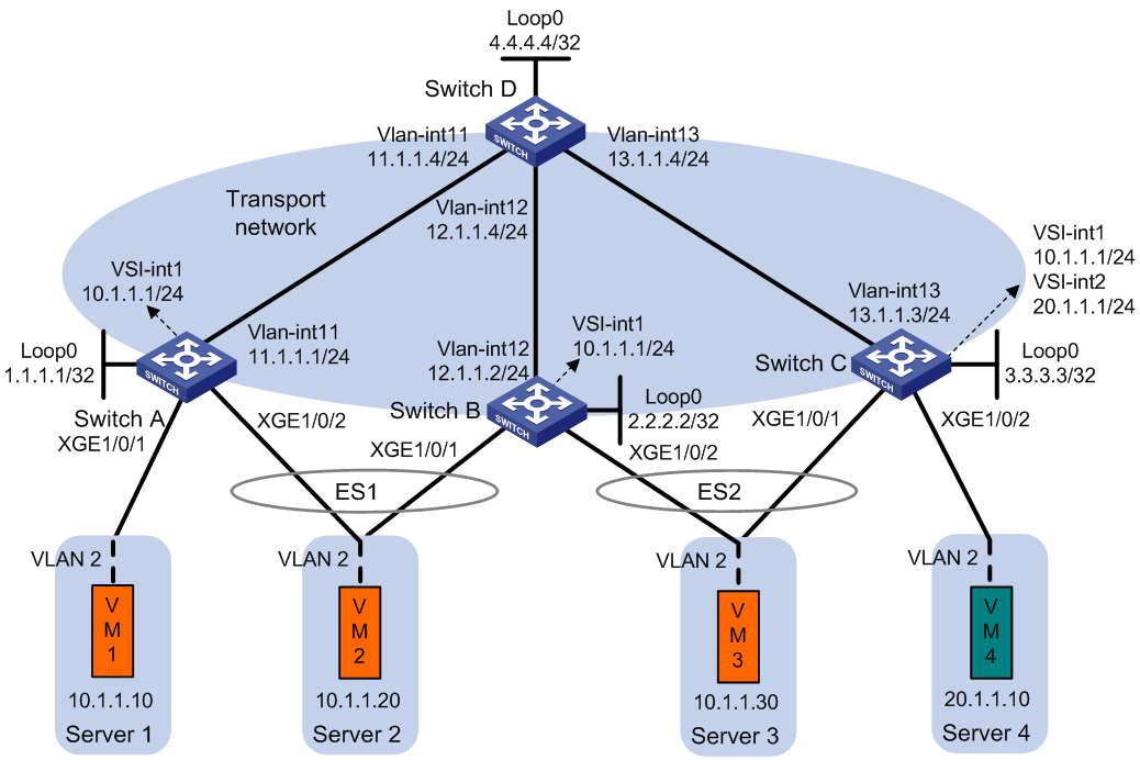
Hardware compatibility
This configuration example is not supported by the S6820 switch series and S6800 switches labeled with the following product codes:
· LS-6800-2C.
· LS-6800-32Q.
· LS-6800-4C.
Procedure
1. Set the VXLAN hardware resource mode on Switch A, Switch B, and Switch C and reboot the switches for the mode to take effect. This step uses Switch A as an example.
<SwitchA> system-view
[SwitchA] hardware-resource vxlan l3gw16k
Do you want to change the specified hardware resource working mode? [Y/N]:y
The hardware resource working mode is changed, please save the configuration and
reboot the system to make it effective.
[SwitchA] quit
<SwitchA> reboot
Start to check configuration with next startup configuration file, please wait..
.......DONE!
Current configuration may be lost after the reboot, save current configuration?
[Y/N]:y
This command will reboot the device. Continue? [Y/N]:y
2. On VM 1, VM 2, and VM 3, specify 10.1.1.1 as the gateway address. On VM 4, specify 20.1.1.1 as the gateway address. (Details not shown.)
3. Configure IP addresses and unicast routing settings:
# Assign IP addresses to the interfaces, as shown in Figure 26. (Details not shown.)
# Configure OSPF on all transport network switches (Switches A through D) for them to reach one another. (Details not shown.)
4. Configure Switch A:
# Enable L2VPN.
<SwitchA> system-view
[SwitchA] l2vpn enable
# Disable remote MAC address learning and remote ARP learning.
[SwitchA] vxlan tunnel mac-learning disable
[SwitchA] vxlan tunnel arp-learning disable
# Create an EVPN instance on VSI vpna, and configure the switch to automatically generate an RD and a route target for the EVPN instance.
[SwitchA] vsi vpna
[SwitchA-vsi-vpna] evpn encapsulation vxlan
[SwitchA-vsi-vpna-evpn-vxlan] route-distinguisher auto router-id
[SwitchA-vsi-vpna-evpn-vxlan] vpn-target auto
[SwitchA-vsi-vpna-evpn-vxlan] quit
# Create VXLAN 10.
[SwitchA-vsi-vpna] vxlan 10
[SwitchA-vsi-vpna-vxlan-10] quit
[SwitchA-vsi-vpna] quit
# Configure BGP to advertise BGP EVPN routes.
[SwitchA] bgp 200
[SwitchA-bgp-default] peer 4.4.4.4 as-number 200
[SwitchA-bgp-default] peer 4.4.4.4 connect-interface loopback 0
[SwitchA-bgp-default] address-family l2vpn evpn
[SwitchA-bgp-default-evpn] peer 4.4.4.4 enable
[SwitchA-bgp-default-evpn] quit
[SwitchA-bgp-default] quit
# On Ten-GigabitEthernet 1/0/1, create Ethernet service instance 1000 to match VLAN 2.
[SwitchA] interface ten-gigabitethernet 1/0/1
[SwitchA-Ten-GigabitEthernet1/0/1] service-instance 1000
[SwitchA-Ten-GigabitEthernet1/0/1-srv1000] encapsulation s-vid 2
# Map Ethernet service instance 1000 to VSI vpna.
[SwitchA-Ten-GigabitEthernet1/0/1-srv1000] xconnect vsi vpna
[SwitchA-Ten-GigabitEthernet1/0/1-srv1000] quit
[SwitchA-Ten-GigabitEthernet1/0/1] quit
# Assign an ESI to Ten-GigabitEthernet 1/0/2.
[SwitchA] interface ten-gigabitethernet 1/0/2
[SwitchA-Ten-GigabitEthernet1/0/2] esi 0.0.0.0.1
# On Ten-GigabitEthernet 1/0/2, create Ethernet service instance 2000 to match VLAN 2.
[SwitchA-Ten-GigabitEthernet1/0/2] service-instance 2000
[SwitchA-Ten-GigabitEthernet1/0/2-srv2000] encapsulation s-vid 2
# Map Ethernet service instance 2000 to VSI vpna.
[SwitchA-Ten-GigabitEthernet1/0/2-srv2000] xconnect vsi vpna
[SwitchA-Ten-GigabitEthernet1/0/2-srv2000] quit
[SwitchA-Ten-GigabitEthernet1/0/2] quit
# Configure RD and route target settings for VPN instance l3vpna.
[SwitchA] ip vpn-instance l3vpna
[SwitchA-vpn-instance-l3vpna] route-distinguisher 1:1
[SwitchA-vpn-instance-l3vpna] address-family ipv4
[SwitchA-vpn-ipv4-l3vpna] vpn-target 2:2
[SwitchA-vpn-ipv4-l3vpna] quit
[SwitchA-vpn-instance-l3vpna] address-family evpn
[SwitchA-vpn-evpn-l3vpna] vpn-target 1:1
[SwitchA-vpn-evpn-l3vpna] quit
[SwitchA-vpn-instance-l3vpna] quit
# Configure VSI-interface 1.
[SwitchA] interface vsi-interface 1
[SwitchA-Vsi-interface1] ip binding vpn-instance l3vpna
[SwitchA-Vsi-interface1] ip address 10.1.1.1 255.255.255.0
[SwitchA-Vsi-interface1] mac-address 1-1-1
[SwitchA-Vsi-interface1] distributed-gateway local
[SwitchA-Vsi-interface1] local-proxy-arp enable
[SwitchA-Vsi-interface1] quit
# Associate VSI-interface 3 with VPN instance l3vpna, and configure the L3 VXLAN ID as 1000 for the VPN instance.
[SwitchA] interface vsi-interface 3
[SwitchA-Vsi-interface3] ip binding vpn-instance l3vpna
[SwitchA-Vsi-interface3] l3-vni 1000
[SwitchA-Vsi-interface3] quit
# Specify VSI-interface 1 as the gateway interface for VSI vpna.
[SwitchA] vsi vpna
[SwitchA-vsi-vpna] gateway vsi-interface 1
[SwitchA-vsi-vpna] quit
5. Configure Switch B:
# Enable L2VPN.
<SwitchB> system-view
[SwitchB] l2vpn enable
# Disable remote MAC address learning and remote ARP learning.
[SwitchB] vxlan tunnel mac-learning disable
[SwitchB] vxlan tunnel arp-learning disable
# Create an EVPN instance on VSI vpna, and configure the switch to automatically generate an RD and a route target for the EVPN instance.
[SwitchB] vsi vpna
[SwitchB-vsi-vpna] evpn encapsulation vxlan
[SwitchB-vsi-vpna-evpn-vxlan] route-distinguisher auto router-id
[SwitchB-vsi-vpna-evpn-vxlan] vpn-target auto
[SwitchB-vsi-vpna-evpn-vxlan] quit
# Create VXLAN 10.
[SwitchB-vsi-vpna] vxlan 10
[SwitchB-vsi-vpna-vxlan-10] quit
[SwitchB-vsi-vpna] quit
# Configure BGP to advertise BGP EVPN routes.
[SwitchB] bgp 200
[SwitchB-bgp-default] peer 4.4.4.4 as-number 200
[SwitchB-bgp-default] peer 4.4.4.4 connect-interface loopback 0
[SwitchB-bgp-default] address-family l2vpn evpn
[SwitchB-bgp-default-evpn] peer 4.4.4.4 enable
[SwitchB-bgp-default-evpn] quit
[SwitchB-bgp-default] quit
# Assign an ESI to Ten-GigabitEthernet 1/0/1.
[SwitchB] interface ten-gigabitethernet 1/0/1
[SwitchB-Ten-GigabitEthernet1/0/1] esi 0.0.0.0.1
# On Ten-GigabitEthernet 1/0/1, create Ethernet service instance 2000 to match VLAN 2.
[SwitchB-Ten-GigabitEthernet1/0/1] service-instance 2000
[SwitchB-Ten-GigabitEthernet1/0/1-srv2000] encapsulation s-vid 2
# Map Ethernet service instance 2000 to VSI vpna.
[SwitchB-Ten-GigabitEthernet1/0/1-srv2000] xconnect vsi vpna
[SwitchB-Ten-GigabitEthernet1/0/1-srv2000] quit
[SwitchB-Ten-GigabitEthernet1/0/1] quit
# Assign an ESI to Ten-GigabitEthernet 1/0/2.
[SwitchB] interface ten-gigabitethernet 1/0/2
[SwitchB-Ten-GigabitEthernet1/0/2] esi 0.0.0.0.2
# On Ten-GigabitEthernet 1/0/2, create Ethernet service instance 3000 to match VLAN 2.
[SwitchB-Ten-GigabitEthernet1/0/2] service-instance 3000
[SwitchB-Ten-GigabitEthernet1/0/2-srv3000] encapsulation s-vid 2
# Map Ethernet service instance 3000 to VSI vpna.
[SwitchB-Ten-GigabitEthernet1/0/2-srv3000] xconnect vsi vpna
[SwitchB-Ten-GigabitEthernet1/0/2-srv3000] quit
[SwitchB-Ten-GigabitEthernet1/0/2] quit
# Configure RD and route target settings for VPN instance l3vpna.
[SwitchB] ip vpn-instance l3vpna
[SwitchB-vpn-instance-l3vpna] route-distinguisher 2:2
[SwitchB-vpn-instance-l3vpna] address-family ipv4
[SwitchB-vpn-ipv4-l3vpna] vpn-target 2:2
[SwitchB-vpn-ipv4-l3vpna] quit
[SwitchB-vpn-instance-l3vpna] address-family evpn
[SwitchB-vpn-evpn-l3vpna] vpn-target 1:1
[SwitchB-vpn-evpn-l3vpna] quit
[SwitchB-vpn-instance-l3vpna] quit
# Configure VSI-interface 1.
[SwitchB] interface vsi-interface 1
[SwitchB-Vsi-interface1] ip binding vpn-instance l3vpna
[SwitchB-Vsi-interface1] ip address 10.1.1.1 255.255.255.0
[SwitchB-Vsi-interface1] mac-address 1-1-1
[SwitchB-Vsi-interface1] distributed-gateway local
[SwitchB-Vsi-interface1] local-proxy-arp enable
[SwitchB-Vsi-interface1] quit
# Associate VSI-interface 3 with VPN instance l3vpna, and configure the L3 VXLAN ID as 1000 for the VPN instance.
[SwitchB] interface vsi-interface 3
[SwitchB-Vsi-interface3] ip binding vpn-instance l3vpna
[SwitchB-Vsi-interface3] l3-vni 1000
[SwitchB-Vsi-interface3] quit
# Specify VSI-interface 1 as the gateway interface for VSI vpna.
[SwitchB] vsi vpna
[SwitchB-vsi-vpna] gateway vsi-interface 1
[SwitchB-vsi-vpna] quit
6. Configure Switch C:
# Enable L2VPN.
<SwitchC> system-view
[SwitchC] l2vpn enable
# Disable remote MAC address learning and remote ARP learning.
[SwitchC] vxlan tunnel mac-learning disable
[SwitchC] vxlan tunnel arp-learning disable
# Create an EVPN instance on VSI vpna, and configure the switch to automatically generate an RD and a route target for the EVPN instance.
[SwitchC] vsi vpna
[SwitchC-vsi-vpna] evpn encapsulation vxlan
[SwitchC-vsi-vpna-evpn-vxlan] route-distinguisher auto router-id
[SwitchC-vsi-vpna-evpn-vxlan] vpn-target auto
[SwitchC-vsi-vpna-evpn-vxlan] quit
# Create VXLAN 10.
[SwitchC-vsi-vpna] vxlan 10
[SwitchC-vsi-vpna-vxlan-10] quit
[SwitchC-vsi-vpna] quit
# Create an EVPN instance on VSI vpnb, and configure the switch to automatically generate an RD and a route target for the EVPN instance.
[SwitchC] vsi vpnb
[SwitchC-vsi-vpnb] evpn encapsulation vxlan
[SwitchC-vsi-vpnb-evpn-vxlan] route-distinguisher auto router-id
[SwitchC-vsi-vpnb-evpn-vxlan] vpn-target auto
[SwitchC-vsi-vpnb-evpn-vxlan] quit
# Create VXLAN 20.
[SwitchC-vsi-vpnb] vxlan 20
[SwitchC-vsi-vpnb-vxlan-20] quit
[SwitchC-vsi-vpnb] quit
# Configure BGP to advertise BGP EVPN routes.
[SwitchC] bgp 200
[SwitchC-bgp-default] peer 4.4.4.4 as-number 200
[SwitchC-bgp-default] peer 4.4.4.4 connect-interface loopback 0
[SwitchC-bgp-default] address-family l2vpn evpn
[SwitchC-bgp-default-evpn] peer 4.4.4.4 enable
[SwitchC-bgp-default-evpn] quit
[SwitchC-bgp-default] quit
# Assign an ESI to Ten-GigabitEthernet 1/0/1.
[SwitchC] interface ten-gigabitethernet 1/0/1
[SwitchC-Ten-GigabitEthernet1/0/1] esi 0.0.0.0.2
# On Ten-GigabitEthernet 1/0/1, create Ethernet service instance 3000 to match VLAN 2.
[SwitchC-Ten-GigabitEthernet1/0/1] service-instance 3000
[SwitchC-Ten-GigabitEthernet1/0/1-srv3000] encapsulation s-vid 2
# Map Ethernet service instance 3000 to VSI vpna.
[SwitchC-Ten-GigabitEthernet1/0/1-srv3000] xconnect vsi vpna
[SwitchC-Ten-GigabitEthernet1/0/1-srv3000] quit
[SwitchC-Ten-GigabitEthernet1/0/1] quit
# On Ten-GigabitEthernet 1/0/2, create Ethernet service instance 4000 to match VLAN 3.
[SwitchC] interface ten-gigabitethernet 1/0/2
[SwitchC-Ten-GigabitEthernet1/0/2] service-instance 4000
[SwitchC-Ten-GigabitEthernet1/0/2-srv4000] encapsulation s-vid 3
# Map Ethernet service instance 4000 to VSI vpnb.
[SwitchC-Ten-GigabitEthernet1/0/2-srv4000] xconnect vsi vpnb
[SwitchC-Ten-GigabitEthernet1/0/2-srv4000] quit
[SwitchC-Ten-GigabitEthernet1/0/2] quit
# Configure RD and route target settings for VPN instance l3vpna.
[SwitchC] ip vpn-instance l3vpna
[SwitchC-vpn-instance-l3vpna] route-distinguisher 3:3
[SwitchC-vpn-instance-l3vpna] address-family ipv4
[SwitchC-vpn-ipv4-l3vpna] vpn-target 2:2
[SwitchC-vpn-ipv4-l3vpna] quit
[SwitchC-vpn-instance-l3vpna] address-family evpn
[SwitchC-vpn-evpn-l3vpna] vpn-target 1:1
[SwitchC-vpn-evpn-l3vpna] quit
[SwitchC-vpn-instance-l3vpna] quit
# Configure VSI-interface 1.
[SwitchC] interface vsi-interface 1
[SwitchC-Vsi-interface1] ip binding vpn-instance l3vpna
[SwitchC-Vsi-interface1] ip address 10.1.1.1 255.255.255.0
[SwitchC-Vsi-interface1] mac-address 1-1-1
[SwitchC-Vsi-interface1] distributed-gateway local
[SwitchC-Vsi-interface1] local-proxy-arp enable
[SwitchC-Vsi-interface1] quit
# Configure VSI-interface 2.
[SwitchC] interface vsi-interface 2
[SwitchC-Vsi-interface2] ip binding vpn-instance l3vpna
[SwitchC-Vsi-interface2] ip address 20.1.1.1 255.255.255.0
[SwitchC-Vsi-interface2] mac-address 2-2-2
[SwitchC-Vsi-interface2] distributed-gateway local
[SwitchC-Vsi-interface2] local-proxy-arp enable
[SwitchC-Vsi-interface2] quit
# Associate VSI-interface 3 with VPN instance l3vpna, and configure the L3 VXLAN ID as 1000 for the VPN instance.
[SwitchC] interface vsi-interface 3
[SwitchC-Vsi-interface3] ip binding vpn-instance l3vpna
[SwitchC-Vsi-interface3] l3-vni 1000
[SwitchC-Vsi-interface3] quit
# Specify VSI-interface 1 as the gateway interface for VSI vpna.
[SwitchC] vsi vpna
[SwitchC-vsi-vpna] gateway vsi-interface 1
[SwitchC-vsi-vpna] quit
# Specify VSI-interface 2 as the gateway interface for VSI vpnb.
[SwitchC] vsi vpnb
[SwitchC-vsi-vpnb] gateway vsi-interface 2
[SwitchC-vsi-vpnb] quit
7. Configure Switch D:
# Establish BGP connections with other transport network switches.
<SwitchD> system-view
[SwitchD] bgp 200
[SwitchD-bgp-default] group evpn
[SwitchD-bgp-default] peer 1.1.1.1 group evpn
[SwitchD-bgp-default] peer 2.2.2.2 group evpn
[SwitchD-bgp-default] peer 3.3.3.3 group evpn
[SwitchD-bgp-default] peer evpn as-number 200
[SwitchD-bgp-default] peer evpn connect-interface loopback 0
# Configure BGP to advertise BGP EVPN routes, and disable route target filtering for BGP EVPN routes.
[SwitchD-bgp-default] address-family l2vpn evpn
[SwitchD-bgp-default-evpn] peer evpn enable
[SwitchD-bgp-default-evpn] undo policy vpn-target
# Configure Switch D as an RR.
[SwitchD-bgp-default-evpn] peer evpn reflect-client
[SwitchD-bgp-default-evpn] quit
[SwitchD-bgp-default] quit
Verifying the configuration
1. Verify the EVPN multihoming configuration on Switch C.
# Verify that Switch C has advertised and received the following BGP EVPN routes:
¡ IP prefix advertisement routes for the gateways.
¡ IMET routes for VSIs.
¡ MAC/IP advertisement routes.
¡ Ethernet auto-discovery routes and Ethernet segment routes.
<SwitchC> display bgp l2vpn evpn
BGP local router ID is 3.3.3.3
Status codes: * - valid, > - best, d - dampened, h - history
s - suppressed, S - stale, i - internal, e - external
a - additional-path
Origin: i - IGP, e - EGP, ? - incomplete
Total number of routes from all PEs: 17
Route distinguisher: 1:1
Total number of routes: 1
* >i Network : [5][0][24][10.1.1.0]/80
NextHop : 1.1.1.1 LocPrf : 100
PrefVal : 0 OutLabel : NULL
MED : 0
Path/Ogn: i
Route distinguisher: 2:2
Total number of routes: 1
* >i Network : [5][0][24][10.1.1.0]/80
NextHop : 2.2.2.2 LocPrf : 100
PrefVal : 0 OutLabel : NULL
MED : 0
Path/Ogn: i
Route distinguisher: 3:3(l3vpna)
Total number of routes: 10
* >i Network : [1][0000.0000.0000.0000.0001][2]/120
NextHop : 1.1.1.1 LocPrf : 100
PrefVal : 0 OutLabel : NULL
MED : 0
Path/Ogn: i
* i Network : [1][0000.0000.0000.0000.0001][2]/120
NextHop : 2.2.2.2 LocPrf : 100
PrefVal : 0 OutLabel : NULL
MED : 0
Path/Ogn: i
* >i Network : [1][0000.0000.0000.0000.0001][4294967295]/120
NextHop : 1.1.1.1 LocPrf : 100
PrefVal : 0 OutLabel : NULL
MED : 0
Path/Ogn: i
* i Network : [1][0000.0000.0000.0000.0001][4294967295]/120
NextHop : 2.2.2.2 LocPrf : 100
PrefVal : 0 OutLabel : NULL
MED : 0
Path/Ogn: i
* >i Network : [1][0000.0000.0000.0000.0002][2]/120
NextHop : 2.2.2.2 LocPrf : 100
PrefVal : 0 OutLabel : NULL
MED : 0
Path/Ogn: i
* >i Network : [1][0000.0000.0000.0000.0002][4294967295]/120
NextHop : 2.2.2.2 LocPrf : 100
PrefVal : 0 OutLabel : NULL
MED : 0
Path/Ogn: i
* >i Network : [2][2][48][0001-0001-0010][32][10.1.1.10]/136
NextHop : 1.1.1.1 LocPrf : 100
PrefVal : 0 OutLabel : NULL
MED : 0
Path/Ogn: i
* >i Network : [2][2][48][0001-0001-0020][32][10.1.1.20]/136
NextHop : 2.2.2.2 LocPrf : 100
PrefVal : 0 OutLabel : NULL
MED : 0
Path/Ogn: i
* > Network : [5][0][24][10.1.1.0]/80
NextHop : 0.0.0.0 LocPrf : 100
PrefVal : 0 OutLabel : NULL
MED : 0
Path/Ogn: i
* > Network : [5][0][24][20.1.1.0]/80
NextHop : 0.0.0.0 LocPrf : 100
PrefVal : 0 OutLabel : NULL
MED : 0
Path/Ogn: i
Route distinguisher: 1.1.1.1:0
Total number of routes: 1
* >i Network : [4][0000.0000.0000.0000.0001][32][1.1.1.1]/128
NextHop : 1.1.1.1 LocPrf : 100
PrefVal : 0 OutLabel : NULL
MED : 0
Path/Ogn: i
Route distinguisher: 1.1.1.1:1
Total number of routes: 5
* >i Network : [1][0000.0000.0000.0000.0001][2]/120
NextHop : 1.1.1.1 LocPrf : 100
PrefVal : 0 OutLabel : NULL
MED : 0
Path/Ogn: i
* >i Network : [1][0000.0000.0000.0000.0001][4294967295]/120
NextHop : 1.1.1.1 LocPrf : 100
PrefVal : 0 OutLabel : NULL
MED : 0
Path/Ogn: i
* >i Network : [2][2][48][0001-0001-0010][0][0.0.0.0]/104
NextHop : 1.1.1.1 LocPrf : 100
PrefVal : 0 OutLabel : NULL
MED : 0
Path/Ogn: i
* >i Network : [2][2][48][0001-0001-0010][32][10.1.1.10]/136
NextHop : 2.2.2.2 LocPrf : 100
PrefVal : 0 OutLabel : NULL
MED : 0
Path/Ogn: i
* >i Network : [3][0][32][1.1.1.1]/80
NextHop : 2.2.2.2 LocPrf : 100
PrefVal : 0 OutLabel : NULL
MED : 0
Path/Ogn: i
Route distinguisher: 2.2.2.2:0
Total number of routes: 2
* >i Network : [4][0000.0000.0000.0000.0001][32][2.2.2.2]/128
NextHop : 2.2.2.2 LocPrf : 100
PrefVal : 0 OutLabel : NULL
MED : 0
Path/Ogn: i
* >i Network : [4][0000.0000.0000.0000.0002][32][2.2.2.2]/128
NextHop : 2.2.2.2 LocPrf : 100
PrefVal : 0 OutLabel : NULL
MED : 0
Path/Ogn: i
Route distinguisher: 2.2.2.2:1
Total number of routes: 7
* >i Network : [1][0000.0000.0000.0000.0001][2]/120
NextHop : 2.2.2.2 LocPrf : 100
PrefVal : 0 OutLabel : NULL
MED : 0
Path/Ogn: i
* >i Network : [1][0000.0000.0000.0000.0001][4294967295]/120
NextHop : 2.2.2.2 LocPrf : 100
PrefVal : 0 OutLabel : NULL
MED : 0
Path/Ogn: i
* >i Network : [1][0000.0000.0000.0000.0002][2]/120
NextHop : 2.2.2.2 LocPrf : 100
PrefVal : 0 OutLabel : NULL
MED : 0
Path/Ogn: i
* >i Network : [1][0000.0000.0000.0000.0002][4294967295]/120
NextHop : 2.2.2.2 LocPrf : 100
PrefVal : 0 OutLabel : NULL
MED : 0
Path/Ogn: i
* >i Network : [2][2][48][0001-0001-0020][0][0.0.0.0]/104
NextHop : 2.2.2.2 LocPrf : 100
PrefVal : 0 OutLabel : NULL
MED : 0
Path/Ogn: i
* >i Network : [2][2][48][0001-0001-0020][32][10.1.1.20]/136
NextHop : 2.2.2.2 LocPrf : 100
PrefVal : 0 OutLabel : NULL
MED : 0
Path/Ogn: i
* >i Network : [3][0][32][2.2.2.2]/80
NextHop : 2.2.2.2 LocPrf : 100
PrefVal : 0 OutLabel : NULL
MED : 0
Path/Ogn: i
Route distinguisher: 3.3.3.3:0
Total number of routes: 1
* > Network : [4][0000.0000.0000.0000.0002][32][3.3.3.3]/128
NextHop : 2.2.2.2 LocPrf : 100
PrefVal : 32768 OutLabel : NULL
MED : 0
Path/Ogn: i
Route distinguisher: 3.3.3.3:1
Total number of routes: 5
* > Network : [1][0000.0000.0000.0000.0002][2]/120
NextHop : 0.0.0.0 LocPrf : 100
PrefVal : 32768 OutLabel : NULL
MED : 0
Path/Ogn: i
* > Network : [1][0000.0000.0000.0000.0002][4294967295]/120
NextHop : 0.0.0.0 LocPrf : 100
PrefVal : 32768 OutLabel : NULL
MED : 0
Path/Ogn: i
* > Network : [2][2][48][0001-0001-0030][0][0.0.0.0]/104
NextHop : 0.0.0.0 LocPrf : 100
PrefVal : 32768 OutLabel : NULL
MED : 0
Path/Ogn: i
* > Network : [2][2][48][0001-0001-0030][32][10.1.1.30]/136
NextHop : 0.0.0.0 LocPrf : 100
PrefVal : 32768 OutLabel : NULL
MED : 0
Path/Ogn: i
* > Network : [3][0][32][3.3.3.3]/80
NextHop : 0.0.0.0 LocPrf : 100
PrefVal : 32768 OutLabel : NULL
MED : 0
Path/Ogn: i
Route distinguisher: 3.3.3.3:2
Total number of routes: 3
* > Network : [2][2][48][0002-0001-0010][0][0.0.0.0]/104
NextHop : 0.0.0.0 LocPrf : 100
PrefVal : 32768 OutLabel : NULL
MED : 0
Path/Ogn: i
* > Network : [2][2][48][0002-0001-0010][32][20.1.1.10]/136
NextHop : 0.0.0.0 LocPrf : 100
PrefVal : 32768 OutLabel : NULL
MED : 0
Path/Ogn: i
* > Network : [3][0][32][3.3.3.3]/80
NextHop : 0.0.0.0 LocPrf : 100
PrefVal : 32768 OutLabel : NULL
MED : 0
Path/Ogn: i
# Verify that Switch C has ECMP routes to VM 2.
<SwitchC> display evpn routing-table vpn-instance l3vpna
Flags: E - with valid ESI A - AD ready L - Local ES exists
VPN instance:l3vpna Local L3VNI:1000
IP address Next hop Outgoing interface NibID Flags
10.1.1.10 1.1.1.1 Vsi-interface3 0x18000001 -
10.1.1.20 2.2.2.2 Vsi-interface3 0x18000000 EA
1.1.1.1 Vsi-interface3 0x18000001 EA
# Verify that Switch C has equal-cost L2VPN MAC address entries and EVPN MAC address entries for VM 2.
<SwitchC> display l2vpn mac-address
MAC Address State VSI Name Link ID/Name Aging
0001-0001-0010 EVPN vpna Tunnel0 NotAging
0001-0001-0020 EVPN vpna Tunnel0 NotAging
Tunnel1 NotAging
0001-0001-0030 Dynamic vpna XGE1/0/1 NotAging
0002-0001-0010 Dynamic vpnb XGE1/0/2 NotAging
<SwitchC> display evpn route mac
Flags: D - Dynamic B - BGP L - Local active
G - Gateway S - Static M - Mapping I - Invalid
VSI name: vpna
MAC address Link ID/Name Flags Next hop
0001-0001-0030 0 DL -
0001-0001-0010 Tunnel0 B 1.1.1.1
0001-0001-0020 Tunnel0 B 1.1.1.1
Tunnel1 B 2.2.2.2
VSI name: vpnb
MAC address Link ID/Name Flags Next hop
0002-0001-0010 0 DL -
# Verify that Switch C has information about local and remote ESs.
<SwitchC> display evpn es local
Redundancy mode: A - All active S - Single active
VSI name : vpna
ESI Tag ID DF address Mode State
0000.0000.0000.0000.0002 - 2.2.2.2 A Up
<SwitchC> display evpn es remote
VSI name : vpna
ESI : 0000.0000.0000.0000.0001
Redundancy mode : All active
A-D per ES routes :
1.1.1.1
2.2.2.2
A-D per EVI routes :
Tag ID Peer IP
- 1.1.1.1
- 2.2.2.2
ESI : 0000.0000.0000.0000.0002
Redundancy mode : All active
Ethernet segment routes :
2.2.2.2
A-D per ES routes :
2.2.2.2
A-D per EVI routes :
Tag ID Peer IP
- 2.2.2.2
2. Verify that the VMs can communicate with one another. (Details not shown.)
Example: Configuring EVPN multicast
Network configuration
As shown in Figure 27:
· Enable multicast on Switch A, Switch B, and Switch C.
· Configure VXLAN 10 on Switch A, Switch B, and Switch C. Configure Switch A and Switch B as redundant VTEPs for Server 2, and configure Switch B and Switch C as redundant VTEPs for Server 3.
· Configure Switch A, Switch B, and Switch C as distributed EVPN gateways.
· Configure Switch D as an RR to reflect BGP EVPN routes between Switch A, Switch B, and Switch C.
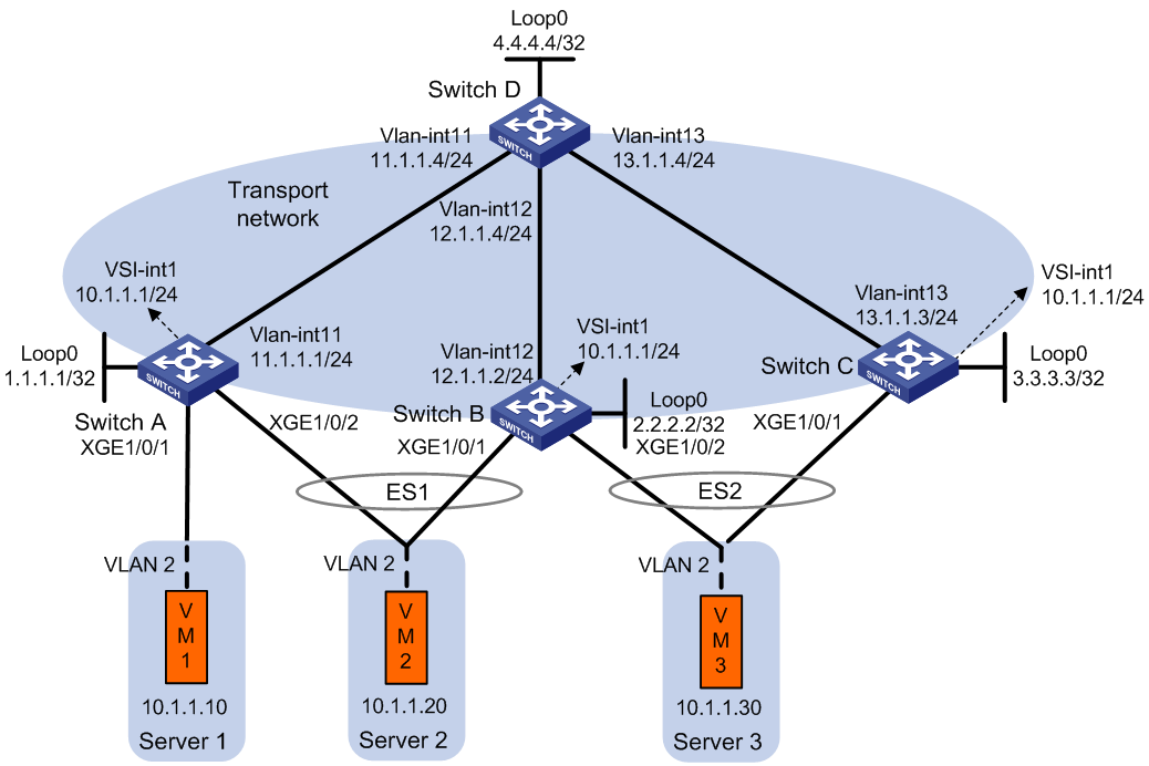
Hardware compatibility
This configuration example is not supported by the S6820 switch series and S6800 switches labeled with the following product codes:
· LS-6800-2C.
· LS-6800-32Q.
· LS-6800-4C.
Procedure
1. Set the VXLAN hardware resource mode on Switch A, Switch B, and Switch C and reboot the switches for the mode to take effect. This step uses Switch A as an example.
<SwitchA> system-view
[SwitchA] hardware-resource vxlan l3gw16k
Do you want to change the specified hardware resource working mode? [Y/N]:y
The hardware resource working mode is changed, please save the configuration and
reboot the system to make it effective.
[SwitchA] quit
<SwitchA> reboot
Start to check configuration with next startup configuration file, please wait..
.......DONE!
Current configuration may be lost after the reboot, save current configuration?
[Y/N]:y
This command will reboot the device. Continue? [Y/N]:y
2. On VM 1, VM 2, and VM 3, specify 10.1.1.1 as the gateway address. (Details not shown.)
3. Configure IP addresses and unicast routing settings:
# Assign IP addresses to the interfaces, as shown in Figure 27. (Details not shown.)
# Configure OSPF on all transport network switches (Switches A through D) for them to reach one another. (Details not shown.)
4. Configure Switch A:
# Enable L2VPN.
<SwitchA> system-view
[SwitchA] l2vpn enable
# Disable remote MAC address learning and remote ARP learning.
[SwitchA] vxlan tunnel mac-learning disable
[SwitchA] vxlan tunnel arp-learning disable
# Create an EVPN instance on VSI vpna, and configure the switch to automatically generate an RD and a route target for the EVPN instance.
[SwitchA] vsi vpna
[SwitchA-vsi-vpna] evpn encapsulation vxlan
[SwitchA-vsi-vpna-evpn-vxlan] route-distinguisher auto router-id
[SwitchA-vsi-vpna-evpn-vxlan] vpn-target auto
[SwitchA-vsi-vpna-evpn-vxlan] quit
# Create VXLAN 10.
[SwitchA-vsi-vpna] vxlan 10
[SwitchA-vsi-vpna-vxlan-10] quit
[SwitchA-vsi-vpna] quit
# Configure BGP to advertise BGP EVPN routes.
[SwitchA] bgp 200
[SwitchA-bgp-default] peer 4.4.4.4 as-number 200
[SwitchA-bgp-default] peer 4.4.4.4 connect-interface loopback 0
[SwitchA-bgp-default] address-family l2vpn evpn
[SwitchA-bgp-default-evpn] peer 4.4.4.4 enable
[SwitchA-bgp-default-evpn] quit
[SwitchA-bgp-default] quit
# On Ten-GigabitEthernet 1/0/1, create Ethernet service instance 1000 to match VLAN 2.
[SwitchA] interface ten-gigabitethernet 1/0/1
[SwitchA-Ten-GigabitEthernet1/0/1] service-instance 1000
[SwitchA-Ten-GigabitEthernet1/0/1-srv1000] encapsulation s-vid 2
# Map Ethernet service instance 1000 to VSI vpna.
[SwitchA-Ten-GigabitEthernet1/0/1-srv1000] xconnect vsi vpna
[SwitchA-Ten-GigabitEthernet1/0/1-srv1000] quit
[SwitchA-Ten-GigabitEthernet1/0/1] quit
# Assign an ESI to Ten-GigabitEthernet 1/0/2.
[SwitchA] interface ten-gigabitethernet 1/0/2
[SwitchA-Ten-GigabitEthernet1/0/2] esi 0.0.0.0.1
# On Ten-GigabitEthernet 1/0/2, create Ethernet service instance 2000 to match VLAN 2.
[SwitchA-Ten-GigabitEthernet1/0/2] service-instance 2000
[SwitchA-Ten-GigabitEthernet1/0/2-srv2000] encapsulation s-vid 2
# Map Ethernet service instance 2000 to VSI vpna.
[SwitchA-Ten-GigabitEthernet1/0/2-srv2000] xconnect vsi vpna
[SwitchA-Ten-GigabitEthernet1/0/2-srv2000] quit
[SwitchA-Ten-GigabitEthernet1/0/2] quit
# Configure RD and route target settings for VPN instance l3vpna.
[SwitchA] ip vpn-instance l3vpna
[SwitchA-vpn-instance-l3vpna] route-distinguisher 1:1
[SwitchA-vpn-instance-l3vpna] address-family ipv4
[SwitchA-vpn-ipv4-l3vpna] vpn-target 2:2
[SwitchA-vpn-ipv4-l3vpna] quit
[SwitchA-vpn-instance-l3vpna] address-family evpn
[SwitchA-vpn-evpn-l3vpna] vpn-target 1:1
[SwitchA-vpn-evpn-l3vpna] quit
[SwitchA-vpn-instance-l3vpna] quit
# Configure VSI-interface 1.
[SwitchA] interface vsi-interface 1
[SwitchA-Vsi-interface1] ip binding vpn-instance l3vpna
[SwitchA-Vsi-interface1] ip address 10.1.1.1 255.255.255.0
[SwitchA-Vsi-interface1] mac-address 1-1-1
[SwitchA-Vsi-interface1] distributed-gateway local
[SwitchA-Vsi-interface1] local-proxy-arp enable
[SwitchA-Vsi-interface1] quit
# Associate VSI-interface 3 with VPN instance l3vpna, and configure the L3 VXLAN ID as 1000 for the VPN instance.
[SwitchA] interface vsi-interface 3
[SwitchA-Vsi-interface3] ip binding vpn-instance l3vpna
[SwitchA-Vsi-interface3] l3-vni 1000
[SwitchA-Vsi-interface3] quit
# Specify VSI-interface 1 as the gateway interface for VSI vpna.
[SwitchA] vsi vpna
[SwitchA-vsi-vpna] gateway vsi-interface 1
[SwitchA-vsi-vpna] quit
# Enable IGMP snooping globally.
[SwitchA] igmp-snooping
[SwitchA-igmp-snooping] quit
# Enable IGMP snooping, IGMP snooping proxying, and dropping unknown multicast data on VSI vpna.
[SwitchA] vsi vpna
[SwitchA-vsi-vpna] igmp-snooping enable
[SwitchA-vsi-vpna] igmp-snooping proxy enable
[SwitchA-vsi-vpna] igmp-snooping drop-unknown
# Set the IGMP snooping version and enable the IGMP snooping querier on VSI vpna.
[SwitchA-vsi-vpna] igmp-snooping version 3
[SwitchA-vsi-vpna] igmp-snooping querier
[SwitchA-vsi-vpna] quit
5. Configure Switch B:
# Enable L2VPN.
<SwitchB> system-view
[SwitchB] l2vpn enable
# Disable remote MAC address learning and remote ARP learning.
[SwitchB] vxlan tunnel mac-learning disable
[SwitchB] vxlan tunnel arp-learning disable
# Create an EVPN instance on VSI vpna, and configure the switch to automatically generate an RD and a route target for the EVPN instance.
[SwitchB] vsi vpna
[SwitchB-vsi-vpna] evpn encapsulation vxlan
[SwitchB-vsi-vpna-evpn-vxlan] route-distinguisher auto router-id
[SwitchB-vsi-vpna-evpn-vxlan] vpn-target auto
[SwitchB-vsi-vpna-evpn-vxlan] quit
# Create VXLAN 10.
[SwitchB-vsi-vpna] vxlan 10
[SwitchB-vsi-vpna-vxlan-10] quit
[SwitchB-vsi-vpna] quit
# Configure BGP to advertise BGP EVPN routes.
[SwitchB] bgp 200
[SwitchB-bgp-default] peer 4.4.4.4 as-number 200
[SwitchB-bgp-default] peer 4.4.4.4 connect-interface loopback 0
[SwitchB-bgp-default] address-family l2vpn evpn
[SwitchB-bgp-default-evpn] peer 4.4.4.4 enable
[SwitchB-bgp-default-evpn] quit
[SwitchB-bgp-default] quit
# Assign an ESI to Ten-GigabitEthernet 1/0/1.
[SwitchB] interface ten-gigabitethernet 1/0/1
[SwitchB-Ten-GigabitEthernet1/0/1] esi 0.0.0.0.1
# On Ten-GigabitEthernet 1/0/1, create Ethernet service instance 2000 to match VLAN 2.
[SwitchB-Ten-GigabitEthernet1/0/1] service-instance 2000
[SwitchB-Ten-GigabitEthernet1/0/1-srv2000] encapsulation s-vid 2
# Map Ethernet service instance 2000 to VSI vpna.
[SwitchB-Ten-GigabitEthernet1/0/1-srv2000] xconnect vsi vpna
[SwitchB-Ten-GigabitEthernet1/0/1-srv2000] quit
[SwitchB-Ten-GigabitEthernet1/0/1] quit
# Assign an ESI to Ten-GigabitEthernet 1/0/2.
[SwitchB] interface ten-gigabitethernet 1/0/2
[SwitchB-Ten-GigabitEthernet1/0/2] esi 0.0.0.0.2
# On Ten-GigabitEthernet 1/0/2, create Ethernet service instance 3000 to match VLAN 2.
[SwitchB-Ten-GigabitEthernet1/0/2] service-instance 3000
[SwitchB-Ten-GigabitEthernet1/0/2-srv3000] encapsulation s-vid 2
# Map Ethernet service instance 3000 to VSI vpna.
[SwitchB-Ten-GigabitEthernet1/0/2-srv3000] xconnect vsi vpna
[SwitchB-Ten-GigabitEthernet1/0/2-srv3000] quit
[SwitchB-Ten-GigabitEthernet1/0/2] quit
# Configure RD and route target settings for VPN instance l3vpna.
[SwitchB] ip vpn-instance l3vpna
[SwitchB-vpn-instance-l3vpna] route-distinguisher 2:2
[SwitchB-vpn-instance-l3vpna] address-family ipv4
[SwitchB-vpn-ipv4-l3vpna] vpn-target 2:2
[SwitchB-vpn-ipv4-l3vpna] quit
[SwitchB-vpn-instance-l3vpna] address-family evpn
[SwitchB-vpn-evpn-l3vpna] vpn-target 1:1
[SwitchB-vpn-evpn-l3vpna] quit
[SwitchB-vpn-instance-l3vpna] quit
# Configure VSI-interface 1.
[SwitchB] interface vsi-interface 1
[SwitchB-Vsi-interface1] ip binding vpn-instance l3vpna
[SwitchB-Vsi-interface1] ip address 10.1.1.1 255.255.255.0
[SwitchB-Vsi-interface1] mac-address 1-1-1
[SwitchB-Vsi-interface1] distributed-gateway local
[SwitchB-Vsi-interface1] local-proxy-arp enable
[SwitchB-Vsi-interface1] quit
# Associate VSI-interface 3 with VPN instance l3vpna, and configure the L3 VXLAN ID as 1000 for the VPN instance.
[SwitchB] interface vsi-interface 3
[SwitchB-Vsi-interface3] ip binding vpn-instance l3vpna
[SwitchB-Vsi-interface3] l3-vni 1000
[SwitchB-Vsi-interface3] quit
# Specify VSI-interface 1 as the gateway interface for VSI vpna.
[SwitchB] vsi vpna
[SwitchB-vsi-vpna] gateway vsi-interface 1
[SwitchB-vsi-vpna] quit
# Enable IGMP snooping globally.
[SwitchB] igmp-snooping
[SwitchB-igmp-snooping] quit
# Enable IGMP snooping, IGMP snooping proxying, and dropping unknown multicast data on VSI vpna.
[SwitchB] vsi vpna
[SwitchB-vsi-vpna] igmp-snooping enable
[SwitchB-vsi-vpna] igmp-snooping proxy enable
[SwitchB-vsi-vpna] igmp-snooping drop-unknown
# Set the IGMP snooping version and enable the IGMP snooping querier on VSI vpna.
[SwitchB-vsi-vpna] igmp-snooping version 3
[SwitchB-vsi-vpna] igmp-snooping querier
[SwitchB-vsi-vpna] quit
6. Configure Switch C:
# Enable L2VPN.
<SwitchC> system-view
[SwitchC] l2vpn enable
# Disable remote MAC address learning and remote ARP learning.
[SwitchC] vxlan tunnel mac-learning disable
[SwitchC] vxlan tunnel arp-learning disable
# Create an EVPN instance on VSI vpna, and configure the switch to automatically generate an RD and a route target for the EVPN instance.
[SwitchC] vsi vpna
[SwitchC-vsi-vpna] evpn encapsulation vxlan
[SwitchC-vsi-vpna-evpn-vxlan] route-distinguisher auto router-id
[SwitchC-vsi-vpna-evpn-vxlan] vpn-target auto
[SwitchC-vsi-vpna-evpn-vxlan] quit
# Create VXLAN 10.
[SwitchC-vsi-vpna] vxlan 10
[SwitchC-vsi-vpna-vxlan-10] quit
[SwitchC-vsi-vpna] quit
# Configure BGP to advertise BGP EVPN routes.
[SwitchC] bgp 200
[SwitchC-bgp-default] peer 4.4.4.4 as-number 200
[SwitchC-bgp-default] peer 4.4.4.4 connect-interface loopback 0
[SwitchC-bgp-default] address-family l2vpn evpn
[SwitchC-bgp-default-evpn] peer 4.4.4.4 enable
[SwitchC-bgp-default-evpn] quit
[SwitchC-bgp-default] quit
# Assign an ESI to Ten-GigabitEthernet 1/0/1.
[SwitchC] interface ten-gigabitethernet 1/0/1
[SwitchC-Ten-GigabitEthernet1/0/1] esi 0.0.0.0.2
# On Ten-GigabitEthernet 1/0/1, create Ethernet service instance 3000 to match VLAN 2.
[SwitchC-Ten-GigabitEthernet1/0/1] service-instance 3000
[SwitchC-Ten-GigabitEthernet1/0/1-srv3000] encapsulation s-vid 2
# Map Ethernet service instance 3000 to VSI vpna.
[SwitchC-Ten-GigabitEthernet1/0/1-srv3000] xconnect vsi vpna
[SwitchC-Ten-GigabitEthernet1/0/1-srv3000] quit
[SwitchC-Ten-GigabitEthernet1/0/1] quit
# Configure RD and route target settings for VPN instance l3vpna.
[SwitchC] ip vpn-instance l3vpna
[SwitchC-vpn-instance-l3vpna] route-distinguisher 3:3
[SwitchC-vpn-instance-l3vpna] address-family ipv4
[SwitchC-vpn-ipv4-l3vpna] vpn-target 2:2
[SwitchC-vpn-ipv4-l3vpna] quit
[SwitchC-vpn-instance-l3vpna] address-family evpn
[SwitchC-vpn-evpn-l3vpna] vpn-target 1:1
[SwitchC-vpn-evpn-l3vpna] quit
[SwitchC-vpn-instance-l3vpna] quit
# Configure VSI-interface 1.
[SwitchC] interface vsi-interface 1
[SwitchC-Vsi-interface1] ip binding vpn-instance l3vpna
[SwitchC-Vsi-interface1] ip address 10.1.1.1 255.255.255.0
[SwitchC-Vsi-interface1] mac-address 1-1-1
[SwitchC-Vsi-interface1] distributed-gateway local
[SwitchC-Vsi-interface1] local-proxy-arp enable
[SwitchC-Vsi-interface1] quit
# Associate VSI-interface 3 with VPN instance l3vpna, and configure the L3 VXLAN ID as 1000 for the VPN instance.
[SwitchC] interface vsi-interface 3
[SwitchC-Vsi-interface3] ip binding vpn-instance l3vpna
[SwitchC-Vsi-interface3] l3-vni 1000
[SwitchC-Vsi-interface3] quit
# Specify VSI-interface 1 as the gateway interface for VSI vpna.
[SwitchC] vsi vpna
[SwitchC-vsi-vpna] gateway vsi-interface 1
[SwitchC-vsi-vpna] quit
# Enable IGMP snooping globally.
[SwitchC] igmp-snooping
[SwitchC-igmp-snooping] quit
# Enable IGMP snooping, IGMP snooping proxying, and dropping unknown multicast data on VSI vpna.
[SwitchC] vsi vpna
[SwitchC-vsi-vpna] igmp-snooping enable
[SwitchC-vsi-vpna] igmp-snooping proxy enable
[SwitchC-vsi-vpna] igmp-snooping drop-unknown
# Set the IGMP snooping version and enable the IGMP snooping querier on VSI vpna.
[SwitchC-vsi-vpna] igmp-snooping version 3
[SwitchC-vsi-vpna] igmp-snooping querier
[SwitchC-vsi-vpna] quit
7. Configure Switch D:
# Establish BGP connections with other transport network switches.
<SwitchD> system-view
[SwitchD] bgp 200
[SwitchD-bgp-default] group evpn
[SwitchD-bgp-default] peer 1.1.1.1 group evpn
[SwitchD-bgp-default] peer 2.2.2.2 group evpn
[SwitchD-bgp-default] peer 3.3.3.3 group evpn
[SwitchD-bgp-default] peer evpn as-number 200
[SwitchD-bgp-default] peer evpn connect-interface loopback 0
# Configure BGP to advertise BGP EVPN routes, and disable route target filtering for BGP EVPN routes.
[SwitchD-bgp-default] address-family l2vpn evpn
[SwitchD-bgp-default-evpn] peer evpn enable
[SwitchD-bgp-default-evpn] undo policy vpn-target
# Configure Switch D as an RR.
[SwitchD-bgp-default-evpn] peer evpn reflect-client
[SwitchD-bgp-default-evpn] quit
[SwitchD-bgp-default] quit
Verifying the configuration
1. On Server 1, send an IGMP membership report to multicast group address 225.0.0.1.
2. Verify that Switch B has received the SMET route advertised by Switch A and created a multicast forwarding entry.
<SwitchB> display evpn route smet
VSI name: vpna
Source address : 0.0.0.0
Group address : 225.0.0.1
Local version : -
Peers :
Nexthop Tunnel name Link ID Remote version
1.1.1.1 Tunnel0 0x5000000 v3(E)
<SwitchB> display igmp-snooping evpn-group
Total 1 entries.
VSI vpna: Total 1 entries.
(0.0.0.0, 225.0.0.1)
Host ports (1 in total):
Tun0 (VXLAN ID 10)
3. Verify that Switch B has received the IGMP join synch route advertised by Switch A.
<SwitchB> display evpn route igmp-js
VSI name: vpna
Source address : 0.0.0.0
Group address : 225.0.0.1
Local version : -
Remote version : v3(E)
ESI : 0000.0000.0000.0000.0001
Ethernet tag ID : 2
Interface : XGE1/0/1 srv2000
Peers : 1.1.1.1
Configuring EVPN-DCI
About EVPN-DCI
EVPN data center interconnect (EVPN-DCI) uses VXLAN-DCI tunnels to provide connectivity for data centers over an IP transport network.
EVPN-DCI network model
As shown in Figure 28, the EVPN-DCI network contains VTEPs and edge devices (EDs) located at the edge of the transport network. A VXLAN tunnel is established between a VTEP and an ED, and a VXLAN-DCI tunnel is established between two EDs. VXLAN-DCI tunnels use VXLAN encapsulation. Each ED de-encapsulates incoming VXLAN packets and re-encapsulates them based on the destination before forwarding the packets through a VXLAN or VXLAN-DCI tunnel.
Figure 28 EVPN-DCI network model
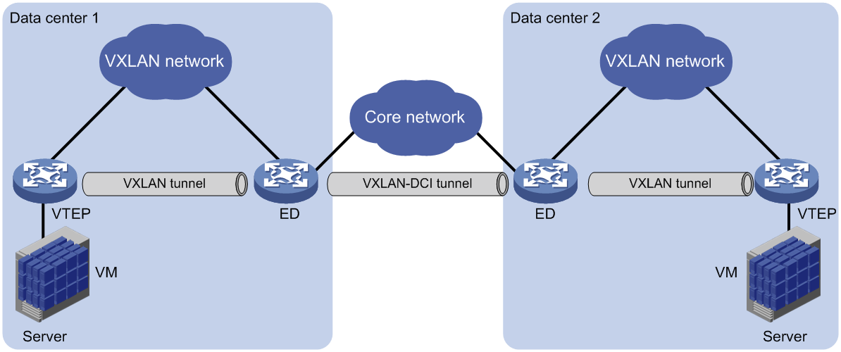
Working mechanisms
In an EVPN-DCI network, BGP EVPN peer relationships are established between EDs and between EDs and VTEPs. When advertising routes to a VTEP or another ED, an ED replaces the routes' nexthop IP address and router MAC address with its IP address and router MAC address.
In an EVPN-DCI network, a VTEP and an ED use a VXLAN tunnel to send traffic, and two EDs use a VXLAN-DCI tunnel to send traffic. An ED de-encapsulates incoming VXLAN packets and re-encapsulates them before forwarding the packets through a VXLAN or VXLAN-DCI tunnel.
EVPN-DCI dual-homing
As shown in Figure 29, EVPN-DCI dual-homing allows you to deploy two EDs at a data center for high availability and load sharing. To virtualize the redundant EDs into one device, a virtual ED address is configured on them. The redundant EDs use the virtual ED address to establish tunnels with VTEPs and remote EDs.
Figure 29 EVPN-DCI dual-homing
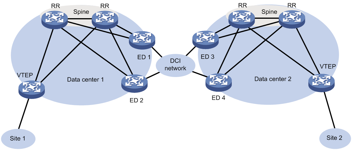
The redundant EDs use their respective IP addresses as the BGP peer addresses to establish BGP EVPN neighbor relationships with VTEPs and remote EDs. The VTEPs and remote EDs send traffic destined for the virtual ED address to both of the redundant EDs through the ECMP routes provided by the underlay network.
The redundant EDs communicate with remote data centers through the transport network. Devices in the dual-homed data center are unaware of the transport network. When the transport-side link fails on one of the redundant EDs, traffic destined for remote data centers is still sent to that ED. To resolve this issue, Monitor Link is used together with EVPN-DCI dual-homing.
On each redundant ED, the transport-facing physical interface is associated with the following loopback interfaces: The loopback interface that provides the IP address used for establishing BGP EVPN neighbor relationships and the loopback interface that provides the virtual ED address. If the transport-side link fails on a redundant ED, the loopback interfaces are placed in down state, and all traffic is forwarded by the other redundant ED. For more information about Monitor Link, see High Availability Configuration Guide.
For link redundancy, deploy multiple RRs on the spine nodes in a data center, and connect each redundant ED to the transport network through multiple links.
Restrictions: Hardware compatibility with EVPN-DCI
EVPN-DCI is not supported by S6800 switches labeled with the following product codes:
· LS-6800-2C.
· LS-6800-32Q.
· LS-6800-4C.
Restrictions and guidelines: EVPN-DCI configuration
You must set the VXLAN hardware resource mode to border on EDs. Otherwise, you cannot manually set up VXLAN-DCI tunnels.
EVPN-DCI tasks at a glance
To configure EVPN-DCI, perform the following tasks on EDs:
1. Enabling DCI
2. Enabling route nexthop replacement and route router MAC replacement
3. (Optional.) Enabling an ED to replace the L3 VXLAN ID and RD of IP prefix advertisement routes
Use this feature to enable communication between data centers that use different L3 VXLAN IDs or hide the L3 VXLAN ID of a data center.
4. (Optional.) Suppressing BGP EVPN route advertisement
To reduce the number of BGP EVPN routes on EDs of an EVPN-DCI network, suppress the advertisement of specific BGP EVPN routes on the EDs.
5. (Optional.) Configuring VXLAN mapping
Perform this task to provide Layer 2 connectivity for a tenant subnet that uses different VXLAN IDs in multiple data centers.
6. Configuring the BGP EVPN address family and the BGP VPNv4 or VPNv6 address family to exchange routesConfiguring the BGP EVPN address family and the BGP VPNv4 or VPNv6 address family to exchange routes
You must perform this task if data centers are interconnected through an MPLS L3VPN network.
7. (Optional.) Configuring EVPN-DCI dual-homing
Prerequisites for EVPN-DCI
Before you configure EVPN-DCI, complete basic EVPN configuration for each data center. For more information about basic EVPN configuration, see "Configuring EVPN."
Enabling DCI
About DCI
For EDs to automatically establish VXLAN-DCI tunnels, you must enable DCI on the Layer 3 Ethernet interfaces or Layer 3 aggregate interfaces that interconnect the EDs.
An ED establishes VXLAN-DCI tunnels based on BGP EVPN routes. If DCI is disabled on the outgoing interfaces to remote sites, EDs cannot establish VXLAN-DCI tunnels.
Procedure
1. Enter system view.
system-view
2. Enter interface view.
interface interface-type interface-number
Subinterfaces of a DCI-enabled interface inherit configuration of the interface.
3. Enable DCI.
dci enable
By default, DCI is disabled on an interface.
Enabling route nexthop replacement and route router MAC replacement
1. Enter system view.
system-view
2. Configure a global router ID.
router id router-id
By default, no global router ID is configured.
3. Enable a BGP instance and enter BGP instance view.
bgp as-number [ instance instance-name ]
By default, BGP is disabled, and no BGP instances exist.
4. Specify local VTEPs and remote EDs as BGP peers.
peer { group-name | ipv4-address [ mask-length ] } as-number as-number
5. Create the BGP EVPN address family and enter BGP EVPN address family view.
address-family l2vpn evpn
6. Enable BGP to exchange BGP EVPN routes with a peer or peer group.
peer { group-name | ipv4-address [ mask-length ] } enable
By default, BGP does not exchange BGP EVPN routes with peers.
7. Set the local router as the next hop for routes advertised to a peer or peer group.
peer { group-name | ipv4-address [ mask-length ] } next-hop-local
The default settings for this command are as follows:
¡ BGP sets the local router as the next hop for all routes advertised to an EBGP peer or peer group.
¡ BGP does not modify the next hop for EBGP routes advertised to an IBGP peer or peer group.
The peers specified in this task must be VTEPs in the local data center.
8. Enable route router MAC replacement for a peer or peer group.
peer { group-name | ipv4-address [ mask-length ] } router-mac-local
By default, the device does not modify the router MAC address of routes before advertising the routes.
This command enables the device to use its router MAC address to replace the router MAC address of routes received from and advertised to a peer or peer group.
The peers specified in this task must be remote EDs.
Enabling an ED to replace the L3 VXLAN ID and RD of IP prefix advertisement routes
About replacement of the L3 VXLAN ID and RD of IP prefix advertisement routes
In an EVPN-DCI network, use this feature to enable communication between data centers that use different L3 VXLAN IDs or hide the L3 VXLAN ID of a data center. After you enable this feature on an ED, the ED performs the following operations after receiving IP prefix advertisement routes:
1. Matches the route targets of the routes with the import route targets of local VPN instances.
2. Replaces the L3 VXLAN ID and RD of the routes with the L3 VXLAN ID and RD of the matching local VPN instance.
3. Advertises the routes to a VTEP or remote ED.
Restrictions and guidelines
After you configure this feature, an ED advertises only IP prefix advertisement routes with the replaced L3 VXLAN ID and RD. The IP prefix advertisement routes with the original L3 VXLAN ID and RD are not advertised.
If the RD of a received IP prefix advertisement route is identical to the RD of the matching local VPN instance, an ED does not replace the L3 VXLAN ID of the route or regenerate the route. As a result, the ED does not advertise the route. As a best practice, assign unique RDs to VPN instances on different EVPN gateways and EDs when you use this feature.
Procedure
1. Enter system view.
system-view
2. Enter BGP instance view.
bgp as-number [ instance instance-name ]
3. Enter BGP EVPN address family view.
address-family l2vpn evpn
4. Replace the L3 VXLAN ID and RD of IP prefix advertisement routes.
peer { group-name | ipv4-address [ mask-length ] } re-originated
By default, the device does not modify the L3 VXLAN ID or RD of the IP prefix advertisement routes that are received from peers or peer groups.
Suppressing BGP EVPN route advertisement
About BGP EVPN route advertisement suppression
To reduce the number of BGP EVPN routes on EDs of an EVPN-DCI network, suppress the advertisement of specific BGP EVPN routes on the EDs.
Restrictions and guidelines
If two VSI interfaces on EVPN gateways of different data centers use the same IP address, do not suppress the advertisement of MAC/IP advertisement routes on the EDs of the data centers. If you suppress the advertisement of these routes, the EDs cannot communicate with each other.
Procedure
1. Enter system view.
system-view
2. Enter BGP instance view.
bgp as-number [ instance instance-name ]
3. Enter BGP EVPN address family view.
address-family l2vpn evpn
4. Suppress the advertisement of specific BGP EVPN routes to a peer or peer group.
peer { group-name | ipv4-address [ mask-length ] } advertise evpn-route suppress { ip-prefix | mac-ip }
By default, advertisement of BGP EVPN routes is not suppressed.
Configuring VXLAN mapping
About VXLAN mapping
The VXLAN mapping feature provides Layer 2 connectivity for a tenant subnet that uses different VXLAN IDs in multiple data centers.
If you map a local VXLAN to a remote VXLAN on an ED, the ED processes routes as follows:
· When the ED receives the local VXLAN's MAC/IP advertisement routes from local VTEPs, it performs the following operations:
¡ Adds the routes to the local VXLAN.
¡ Replaces the VXLAN ID of the routes with the remote VXLAN ID and advertises the routes to remote EDs.
· When the ED receives the remote VXLAN's MAC/IP advertisement routes from a remote data center, it adds the routes to the local VXLAN.
VXLAN mapping includes the following types:
· Non-intermediate VXLAN mapping—When two data centers use different VXLAN IDs for a subnet, map the local VXLAN to the remote VXLAN on the ED of one data center. For example, for VXLAN 10 of data center 1 to communicate with VXLAN 20 of data center 2, map VXLAN 10 to VXLAN 20 on the ED of data center 1.
· Intermediate VXLAN mapping—When multiple data centers use different VXLAN IDs for a subnet, map the VXLANs to an intermediate VXLAN on all EDs. For example, data center 1 uses VXLAN 10, data center 2 uses VXLAN 20, and data center 3 uses VXLAN 30. To provide connectivity for the VXLANs, map them to intermediate VXLAN 500 on EDs of the data centers. You must use intermediate VXLAN mapping if more than two data centers use different VXLAN IDs. The intermediate VXLAN can be used only for VXLAN mapping, and it cannot be used for common VXLAN services.
Restrictions and guidelines
You must create mapped remote VXLANs on the device, create an EVPN instance for each remote VXLAN, and configure RD and route target settings for the EVPN instances.
When you use VXLAN mapping, follow these route target restrictions:
· EVPN instances and EVPN address family of VPN instances do not have the same export targets.
· EVPN instances and EVPN address family of the public instance do not have the same export targets.
Procedure
1. Enter system view.
system-view
2. Enter VSI view.
vsi vsi-name
3. Enter EVPN instance view.
evpn encapsulation vxlan
4. Map the local VXLAN to a remote VXLAN.
mapping vni vxlan-id
By default, a local VXLAN is not mapped to any remote VXLAN.
The remote VXLAN ID cannot be the reserved VXLAN ID specified by using the reserved vxlan command or the L3 VXLAN ID specified by using the l3-vni command. For more information about the reserved vxlan command, see VXLAN Command Reference.
Configuring the BGP EVPN address family and the BGP VPNv4 or VPNv6 address family to exchange routes
About route exchange
When data centers are interconnected through an MPLS L3VPN network, EVPN EDs also act as MPLS L3VPN PEs. To enable communication between the data centers, you must perform the following tasks on the EDs:
· Configure both MPLS L3VPN and EVPN.
· Configure the BGP EVPN address family and the BGP VPNv4 or VPNv6 address family to exchange routes.
Figure 30 Data centers interconnected through an MPLS L3VPN network
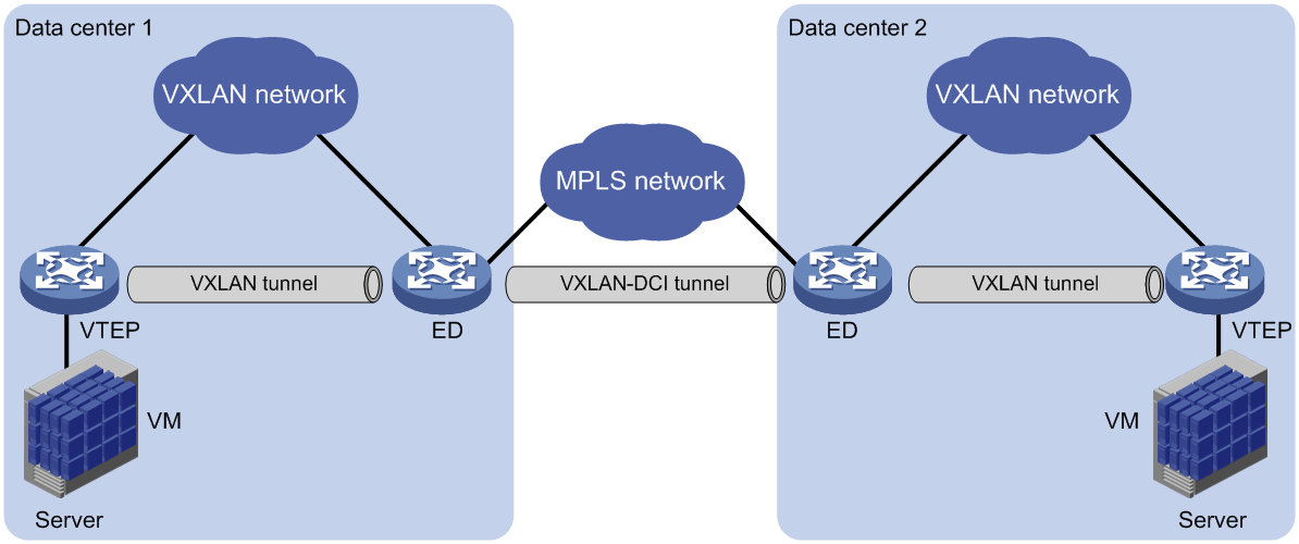
Enabling BGP VPNv4 or VPNv6 route advertisement for the BGP EVPN address family
1. Enter system view.
system-view
2. Enter BGP instance view.
bgp as-number [ instance instance-name ]
3. Enter BGP EVPN address family view.
address-family l2vpn evpn
4. Enable BGP VPNv4 or VPNv6 route advertisement for the BGP EVPN address family.
advertise l3vpn route [ replace-rt ][ advertise-policy policy-name ]
By default, BGP VPNv4 or VPNv6 routes are not advertised through the BGP EVPN address family.
After you execute this command, the device advertises BGP VPNv4 or VPNv6 routes as IP prefix advertisement routes through the BGP EVPN address family.
Enabling BGP EVPN route advertisement for the BGP VPNv4 or VPNv6 address family
1. Enter system view.
system-view
2. Enter BGP instance view.
bgp as-number [ instance instance-name ]
3. Enter BGP VPNv4 address family view or BGP VPNv6 address family view.
address-family { vpnv4 | vpnv6 }
4. Enable BGP EVPN route advertisement for the BGP VPNv4 or VPNv6 address family.
advertise evpn route [ replace-rt ][ advertise-policy policy-name ]
By default, BGP EVPN routes are not advertised through the BGP VPNv4 or VPNv6 address family.
After you execute this command, the device advertises IP prefix advertisement routes and MAC/IP advertisement routes that contain host route information through the BGP VPNv4 or VPNv6 address family.
Configuring EVPN-DCI dual-homing
About EVPN-DCI dual-homing
For high availability and load sharing, you can deploy two EDs at a data center. To virtualize the redundant EDs into one device, you must configure the same virtual ED address on them.
Restrictions and guidelines
Do not configure a virtual ED address on the only ED of a data center.
On a redundant ED, the virtual ED address must be the IP address of a loopback interface, and it cannot be the BGP peer IP address of the ED.
Redundant EDs cannot provide access service for local VMs. They can act only as EDs. For correct communication, do not redistribute external routes on only one of the redundant EDs. However, you can redistribute the same external routes on both EDs.
EVPN-DCI dual-homing is mutually exclusive with EVPN distributed relay. Do not use the evpn edge group and evpn drni group commands together.
Procedure
1. Enter system view.
system-view
2. Configure a virtual ED address.
evpn edge group group-ipv4
By default, no virtual ED address is configured.
EVPN-DCI configuration examples
Example: Configuring a basic EVPN-DCI network (IPv4 underlay network)
Network configuration
As shown in Figure 31:
· Configure VXLAN 10 on Switch A through Switch D to provide connectivity for the VMs in the data centers.
· Configure Switch A and Switch D as VTEPs, and configure Switch B and Switch C as EDs.
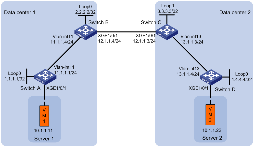
Procedure
1. Set the VXLAN hardware resource mode:
¡ (S6800, S6860, and S6861 switch series.) Set the VXLAN hardware resource mode on Switch B and Switch C and reboot the switches for the mode to take effect. This step uses Switch B as an example.
<SwitchB> system-view
[SwitchB] hardware-resource vxlan border24k
Do you want to change the specified hardware resource working mode? [Y/N]:y
The hardware resource working mode is changed, please save the configuration and
reboot the system to make it effective.
[SwitchB] quit
<SwitchB> reboot
Start to check configuration with next startup configuration file, please wait..
.......DONE!
Current configuration may be lost after the reboot, save current configuration?
[Y/N]:y
This command will reboot the device. Continue? [Y/N]:y
¡ (S6820 switch series.) Set the VXLAN hardware resource mode on Switch B and Switch C and reboot the switches for the mode to take effect. This step uses Switch B as an example.
<SwitchB> system-view
[SwitchB] hardware-resource vxlan border
Do you want to change the specified hardware resource working mode? [Y/N]:y
The hardware resource working mode is changed, please save the configuration and
reboot the system to make it effective.
[SwitchB] quit
<SwitchB> reboot
Start to check configuration with next startup configuration file, please wait..
.......DONE!
Current configuration may be lost after the reboot, save current configuration?
[Y/N]:y
This command will reboot the device. Continue? [Y/N]:y
2. Configure IP addresses and unicast routing settings:
# Assign IP addresses to interfaces, as shown in Figure 31. (Details not shown.)
# Configure OSPF on the transport network for the switches to reach one another. (Details not shown.)
3. Configure Switch A:
# Enable L2VPN.
<SwitchA> system-view
[SwitchA] l2vpn enable
# Disable remote MAC address learning.
[SwitchA] vxlan tunnel mac-learning disable
# Create VXLAN 10 on VSI vpna.
[SwitchA] vsi vpna
[SwitchA-vsi-vpna] vxlan 10
[SwitchA-vsi-vpna-vxlan-10] quit
# Create an EVPN instance on VSI vpna. Configure the switch to automatically generate an RD, and manually configure a route target for the EVPN instance.
[SwitchA-vsi-vpna] evpn encapsulation vxlan
[SwitchA-vsi-vpna-evpn-vxlan] route-distinguisher auto
[SwitchA-vsi-vpna-evpn-vxlan] vpn-target 123:456
[SwitchA-vsi-vpna-evpn-vxlan] quit
[SwitchA-vsi-vpna] quit
# Configure BGP to advertise BGP EVPN routes.
[SwitchA] bgp 100
[SwitchA-bgp-default] peer 2.2.2.2 as-number 100
[SwitchA-bgp-default] peer 2.2.2.2 connect-interface loopback 0
[SwitchA-bgp-default] address-family l2vpn evpn
[SwitchA-bgp-default-evpn] peer 2.2.2.2 enable
[SwitchA-bgp-default-evpn] quit
[SwitchA-bgp-default] quit
# On Ten-GigabitEthernet 1/0/1, create Ethernet service instance 1000 to match VLAN 100.
[SwitchA] interface ten-gigabitethernet 1/0/1
[SwitchA-Ten-GigabitEthernet1/0/1] service-instance 1000
[SwitchA-Ten-GigabitEthernet1/0/1-srv1000] encapsulation s-vid 100
# Map Ethernet service instance 1000 to VSI vpna.
[SwitchA-Ten-GigabitEthernet1/0/1-srv1000] xconnect vsi vpna
[SwitchA-Ten-GigabitEthernet1/0/1-srv1000] quit
4. Configure Switch B:
# Enable L2VPN.
<SwitchB> system-view
[SwitchB] l2vpn enable
# Disable remote MAC address learning.
[SwitchB] vxlan tunnel mac-learning disable
# Enable DCI on the Layer 3 interface that connects Switch B to Switch C for the switches to establish a VXLAN-DCI tunnel.
[SwitchB] interface ten-gigabitethernet 1/0/1
[SwitchB-Ten-GigabitEthernet1/0/1] dci enable
[SwitchB-Ten-GigabitEthernet1/0/1] quit
# Create VXLAN 10 on VSI vpna.
[SwitchB] vsi vpna
[SwitchB-vsi-vpna] vxlan 10
[SwitchB-vsi-vpna-vxlan-10] quit
# Create an EVPN instance on VSI vpna. Configure the switch to automatically generate an RD, and manually configure a route target for the EVPN instance.
[SwitchB-vsi-vpna] evpn encapsulation vxlan
[SwitchB-vsi-vpna-evpn-vxlan] route-distinguisher auto
[SwitchB-vsi-vpna-evpn-vxlan] vpn-target 123:456
[SwitchB-vsi-vpna-evpn-vxlan] quit
[SwitchB-vsi-vpna] quit
# Configure BGP to advertise BGP EVPN routes. Enable nexthop replacement for routes advertised to Switch A, and enable router MAC replacement for routes advertised to and received from Switch C.
[SwitchB] bgp 100
[SwitchB-bgp-default] peer 3.3.3.3 as-number 200
[SwitchB-bgp-default] peer 3.3.3.3 connect-interface loopback 0
[SwitchB-bgp-default] peer 3.3.3.3 ebgp-max-hop 64
[SwitchB-bgp-default] peer 1.1.1.1 as-number 100
[SwitchB-bgp-default] peer 1.1.1.1 connect-interface loopback 0
[SwitchB-bgp-default] address-family l2vpn evpn
[SwitchB-bgp-default-evpn] peer 3.3.3.3 enable
[SwitchB-bgp-default-evpn] peer 3.3.3.3 router-mac-local
[SwitchB-bgp-default-evpn] peer 1.1.1.1 enable
[SwitchB-bgp-default-evpn] peer 1.1.1.1 next-hop-local
[SwitchB-bgp-default-evpn] quit
[SwitchB-bgp-default] quit
5. Configure Switch C:
# Enable L2VPN.
<SwitchC> system-view
[SwitchC] l2vpn enable
# Disable remote MAC address learning.
[SwitchC] vxlan tunnel mac-learning disable
# Enable DCI on the Layer 3 interface that connects Switch C to Switch B for the switches to establish a VXLAN-DCI tunnel.
[SwitchC] interface ten-gigabitethernet 1/0/1
[SwitchC-Ten-GigabitEthernet1/0/1] dci enable
[SwitchC-Ten-GigabitEthernet1/0/1] quit
# Create VXLAN 10 on VSI vpna.
[SwitchC] vsi vpna
[SwitchC-vsi-vpna] vxlan 10
[SwitchC-vsi-vpna-vxlan-10] quit
# Create an EVPN instance on VSI vpna. Configure the switch to automatically generate an RD, and manually configure a route target for the EVPN instance.
[SwitchC-vsi-vpna] evpn encapsulation vxlan
[SwitchC-vsi-vpna-evpn-vxlan] route-distinguisher auto
[SwitchC-vsi-vpna-evpn-vxlan] vpn-target 123:456
[SwitchC-vsi-vpna-evpn-vxlan] quit
[SwitchC-vsi-vpna] quit
# Configure BGP to advertise BGP EVPN routes. Enable nexthop replacement for routes advertised to Switch D, and enable router MAC replacement for routes advertised to and received from Switch B.
[SwitchC] bgp 200
[SwitchC-bgp-default] peer 2.2.2.2 as-number 100
[SwitchC-bgp-default] peer 2.2.2.2 connect-interface loopback 0
[SwitchC-bgp-default] peer 2.2.2.2 ebgp-max-hop 64
[SwitchC-bgp-default] peer 4.4.4.4 as-number 200
[SwitchC-bgp-default] peer 4.4.4.4 connect-interface loopback 0
[SwitchC-bgp-default] address-family l2vpn evpn
[SwitchC-bgp-default-evpn] peer 2.2.2.2 enable
[SwitchC-bgp-default-evpn] peer 2.2.2.2 router-mac-local
[SwitchC-bgp-default-evpn] peer 4.4.4.4 enable
[SwitchC-bgp-default-evpn] peer 4.4.4.4 next-hop-local
[SwitchC-bgp-default-evpn] quit
[SwitchC-bgp-default] quit
6. Configure Switch D:
# Enable L2VPN.
<SwitchD> system-view
[SwitchD] l2vpn enable
# Disable remote MAC address learning.
[SwitchD] vxlan tunnel mac-learning disable
# Create VXLAN 10 on VSI vpna.
[SwitchD] vsi vpna
[SwitchD-vsi-vpna] vxlan 10
[SwitchD-vsi-vpna-vxlan-10] quit
# Create an EVPN instance on VSI vpna. Configure the switch to automatically generate an RD, and manually configure a route target for the EVPN instance.
[SwitchD-vsi-vpna] evpn encapsulation vxlan
[SwitchD-vsi-vpna-evpn-vxlan] route-distinguisher auto
[SwitchD-vsi-vpna-evpn-vxlan] vpn-target 123:456
[SwitchD-vsi-vpna-evpn-vxlan] quit
[SwitchD-vsi-vpna] quit
# Configure BGP to advertise BGP EVPN routes.
[SwitchD] bgp 200
[SwitchD-bgp-default] peer 3.3.3.3 as-number 200
[SwitchD-bgp-default] peer 3.3.3.3 connect-interface Loopback 0
[SwitchD-bgp-default] address-family l2vpn evpn
[SwitchD-bgp-default-evpn] peer 3.3.3.3 enable
[SwitchD-bgp-default-evpn] quit
[SwitchD-bgp-default] quit
# On Ten-GigabitEthernet 1/0/1, create Ethernet service instance 1000 to match VLAN 200.
[SwitchD] interface ten-gigabitethernet 1/0/1
[SwitchD-Ten-GigabitEthernet1/0/1] service-instance 1000
[SwitchD-Ten-GigabitEthernet1/0/1-srv1000] encapsulation s-vid 200
# Map Ethernet service instance 1000 to VSI vpna.
[SwitchD-Ten-GigabitEthernet1/0/1-srv1000] xconnect vsi vpna
[SwitchD-Ten-GigabitEthernet1/0/1-srv1000] quit
Verifying the configuration
1. Verify the configuration on EDs. (This example uses Switch B.)
# Verify that the ED has discovered Switch A and Switch C through IMET routes and has established VXLAN and VXLAN-DCI tunnels to the switches.
[SwitchB] display evpn auto-discovery imet
Total number of automatically discovered peers: 2
VSI name: vpna
RD PE_address Tunnel_address Tunnel mode VXLAN ID
1:10 1.1.1.1 1.1.1.1 VXLAN 10
1:10 3.3.3.3 3.3.3.3 VXLAN-DCI 10
# Verify that the VXLAN and VXLAN-DCI tunnels on the ED are up.
[SwitchB] display interface tunnel
Tunnel0
Current state: UP
Line protocol state: UP
Description: Tunnel0 Interface
Bandwidth: 64 kbps
Maximum transmission unit: 1464
Internet protocol processing: Disabled
Last clearing of counters: Never
Tunnel source 2.2.2.2, destination 1.1.1.1
Tunnel protocol/transport UDP_VXLAN/IP
Last 300 seconds input rate: 0 bytes/sec, 0 bits/sec, 0 packets/sec
Last 300 seconds output rate: 0 bytes/sec, 0 bits/sec, 0 packets/sec
Input: 0 packets, 0 bytes, 0 drops
Output: 0 packets, 0 bytes, 0 drops
Tunnel1
Current state: UP
Line protocol state: UP
Description: Tunnel1 Interface
Bandwidth: 64 kbps
Maximum transmission unit: 1464
Internet protocol processing: Disabled
Last clearing of counters: Never
Tunnel source 2.2.2.2, destination 3.3.3.3
Tunnel protocol/transport UDP_VXLAN-DCI/IP
Last 300 seconds input rate: 0 bytes/sec, 0 bits/sec, 0 packets/sec
Last 300 seconds output rate: 0 bytes/sec, 0 bits/sec, 0 packets/sec
Input: 0 packets, 0 bytes, 0 drops
Output: 0 packets, 0 bytes, 0 drops
# Verify that the VXLAN and VXLAN-DCI tunnels have been assigned to the VXLAN.
[SwitchB] display l2vpn vsi name vpna verbose
VSI Name: vpna
VSI Index : 0
VSI State : Up
MTU : 1500
Bandwidth : Unlimited
Broadcast Restrain : Unlimited
Multicast Restrain : Unlimited
Unknown Unicast Restrain: Unlimited
MAC Learning : Enabled
MAC Table Limit : -
MAC Learning rate : -
Drop Unknown : -
Flooding : Enabled
Statistics : Disabled
VXLAN ID : 10
Tunnels:
Tunnel Name Link ID State Type Flood proxy
Tunnel0 0x5000000 UP Auto Disabled
Tunnel1 0x5000001 UP Auto Disabled
# Verify that the ED has generated EVPN MAC address entries for the VMs.
[SwitchB] display evpn route mac
Flags: D - Dynamic B - BGP L - Local active
G - Gateway S - Static M - Mapping I - Invalid
VSI name: vpna
MAC address Link ID/Name Flags Next hop
0001-0001-0011 Tunnel0 B 1.1.1.1
0001-0001-0033 Tunnel1 B 3.3.3.3
2. Verify that VM 1 and VM 2 can communicate. (Details not shown.)
Example: Configuring EVPN-DCI intermediate VXLAN mapping (IPv4 underlay network)
Network configuration
As shown in Figure 32:
· Configure VXLAN 10 on VTEP Switch A and ED Switch B, and configure VXLAN 30 on VTEP Switch D and ED Switch C.
· Configure intermediate VXLAN mapping for VXLAN 10 and VXLAN 30 to have Layer 2 connectivity:
¡ Map VXLAN 10 to intermediate VXLAN 500 on Switch B.
¡ Map VXLAN 30 to intermediate VXLAN 500 on Switch C.
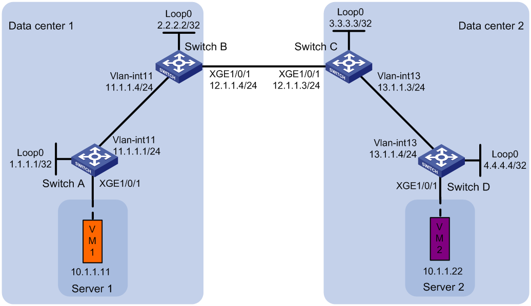
Procedure
1. Set the VXLAN hardware resource mode:
¡ (S6800, S6860, and S6861 switch series.) Set the VXLAN hardware resource mode on Switch B and Switch C and reboot the switches for the mode to take effect. This step uses Switch B as an example.
<SwitchB> system-view
[SwitchB] hardware-resource vxlan border24k
Do you want to change the specified hardware resource working mode? [Y/N]:y
The hardware resource working mode is changed, please save the configuration and
reboot the system to make it effective.
[SwitchB] quit
<SwitchB> reboot
Start to check configuration with next startup configuration file, please wait..
.......DONE!
Current configuration may be lost after the reboot, save current configuration?
[Y/N]:y
This command will reboot the device. Continue? [Y/N]:y
¡ (S6820 switch series.) Set the VXLAN hardware resource mode on Switch B and Switch C and reboot the switches for the mode to take effect. This step uses Switch B as an example.
<SwitchB> system-view
[SwitchB] hardware-resource vxlan border
Do you want to change the specified hardware resource working mode? [Y/N]:y
The hardware resource working mode is changed, please save the configuration and
reboot the system to make it effective.
[SwitchB] quit
<SwitchB> reboot
Start to check configuration with next startup configuration file, please wait..
.......DONE!
Current configuration may be lost after the reboot, save current configuration?
[Y/N]:y
This command will reboot the device. Continue? [Y/N]:y
2. Configure IP addresses and unicast routing settings:
# Assign IP addresses to interfaces, as shown in Figure 32. (Details not shown.)
# Configure OSPF on the transport network for the switches to reach one another. (Details not shown.)
3. Configure Switch A:
# Enable L2VPN.
<SwitchA> system-view
[SwitchA] l2vpn enable
# Disable remote MAC address learning.
[SwitchA] vxlan tunnel mac-learning disable
# Create VXLAN 10 on VSI vpna.
[SwitchA] vsi vpna
[SwitchA-vsi-vpna] vxlan 10
[SwitchA-vsi-vpna-vxlan-10] quit
# Create an EVPN instance on VSI vpna. Configure the switch to automatically generate an RD and a route target for the EVPN instance.
[SwitchA-vsi-vpna] evpn encapsulation vxlan
[SwitchA-vsi-vpna-evpn-vxlan] route-distinguisher auto
[SwitchA-vsi-vpna-evpn-vxlan] vpn-target auto
[SwitchA-vsi-vpna-evpn-vxlan] quit
[SwitchA-vsi-vpna] quit
# Configure BGP to advertise BGP EVPN routes.
[SwitchA] bgp 100
[SwitchA-bgp-default] peer 2.2.2.2 as-number 100
[SwitchA-bgp-default] peer 2.2.2.2 connect-interface loopback 0
[SwitchA-bgp-default] address-family l2vpn evpn
[SwitchA-bgp-default-evpn] peer 2.2.2.2 enable
[SwitchA-bgp-default-evpn] quit
[SwitchA-bgp-default] quit
# On Ten-GigabitEthernet 1/0/1, create Ethernet service instance 1000 to match VLAN 100.
[SwitchA] interface ten-gigabitethernet 1/0/1
[SwitchA-Ten-GigabitEthernet1/0/1] service-instance 1000
[SwitchA-Ten-GigabitEthernet1/0/1-srv1000] encapsulation s-vid 100
# Map Ethernet service instance 1000 to VSI vpna.
[SwitchA-Ten-GigabitEthernet1/0/1-srv1000] xconnect vsi vpna
[SwitchA-Ten-GigabitEthernet1/0/1-srv1000] quit
4. Configure Switch B:
# Enable L2VPN.
<SwitchB> system-view
[SwitchB] l2vpn enable
# Disable remote MAC address learning.
[SwitchB] vxlan tunnel mac-learning disable
# Enable DCI on the Layer 3 interface that connects Switch B to Switch C for the switches to establish a VXLAN-DCI tunnel.
[SwitchB] interface ten-gigabitethernet 1/0/1
[SwitchB-Ten-GigabitEthernet1/0/1] dci enable
[SwitchB-Ten-GigabitEthernet1/0/1] quit
# Create VXLAN 10 on VSI vpna.
[SwitchB] vsi vpna
[SwitchB-vsi-vpna] vxlan 10
[SwitchB-vsi-vpna-vxlan-10] quit
# Create an EVPN instance on VSI vpna. Configure the switch to automatically generate an RD and a route target for the EVPN instance.
[SwitchB-vsi-vpna] evpn encapsulation vxlan
[SwitchB-vsi-vpna-evpn-vxlan] route-distinguisher auto
[SwitchB-vsi-vpna-evpn-vxlan] vpn-target auto
# Map local VXLAN 10 to intermediate VXLAN 500.
[SwitchB-vsi-vpna-evpn-vxlan] mapping vni 500
[SwitchB-vsi-vpna-evpn-vxlan] quit
[SwitchB-vsi-vpna] quit
# Create VXLAN 500 on VSI vpnb. The switch will replace the VXLAN ID of VXLAN 10's traffic with VXLAN ID 500 when performing Layer 2 forwarding.
[SwitchB] vsi vpnb
[SwitchB-vsi-vpnb] vxlan 500
[SwitchB-vsi-vpnb-vxlan-500] quit
# Create an EVPN instance on VSI vpnb. Configure the switch to automatically generate an RD, and manually configure a route target for the EVPN instance.
[SwitchB-vsi-vpnb] evpn encapsulation vxlan
[SwitchB-vsi-vpnb-evpn-vxlan] route-distinguisher auto
[SwitchB-vsi-vpnb-evpn-vxlan] vpn-target 123:456
[SwitchB-vsi-vpnb-evpn-vxlan] quit
[SwitchB-vsi-vpnb] quit
# Configure BGP to advertise BGP EVPN routes. Enable nexthop replacement for routes advertised to Switch A, and enable router MAC replacement for routes advertised to and received from Switch C.
[SwitchB] bgp 100
[SwitchB-bgp-default] peer 3.3.3.3 as-number 200
[SwitchB-bgp-default] peer 3.3.3.3 connect-interface loopback 0
[SwitchB-bgp-default] peer 3.3.3.3 ebgp-max-hop 64
[SwitchB-bgp-default] peer 1.1.1.1 as-number 100
[SwitchB-bgp-default] peer 1.1.1.1 connect-interface loopback 0
[SwitchB-bgp-default] address-family l2vpn evpn
[SwitchB-bgp-default-evpn] peer 3.3.3.3 enable
[SwitchB-bgp-default-evpn] peer 3.3.3.3 router-mac-local
[SwitchB-bgp-default-evpn] peer 1.1.1.1 enable
[SwitchB-bgp-default-evpn] peer 1.1.1.1 next-hop-local
[SwitchB-bgp-default-evpn] quit
[SwitchB-bgp-default] quit
5. Configure Switch C:
# Enable L2VPN.
<SwitchC> system-view
[SwitchC] l2vpn enable
# Disable remote MAC address learning.
[SwitchC] vxlan tunnel mac-learning disable
# Enable DCI on the Layer 3 interface that connects Switch C to Switch B for the switches to establish a VXLAN-DCI tunnel.
[SwitchC] interface ten-gigabitethernet 1/0/1
[SwitchC-Ten-GigabitEthernet1/0/1] dci enable
[SwitchC-Ten-GigabitEthernet1/0/1] quit
# Create VXLAN 30 on VSI vpna.
[SwitchC] vsi vpna
[SwitchC-vsi-vpna] vxlan 30
[SwitchC-vsi-vpna-vxlan-30] quit
# Create an EVPN instance on VSI vpna. Configure the switch to automatically generate an RD and a route target for the EVPN instance.
[SwitchC-vsi-vpna] evpn encapsulation vxlan
[SwitchC-vsi-vpna-evpn-vxlan] route-distinguisher auto
[SwitchC-vsi-vpna-evpn-vxlan] vpn-target auto
# Map local VXLAN 30 to intermediate VXLAN 500.
[SwitchC-vsi-vpna-evpn-vxlan] mapping vni 500
[SwitchC-vsi-vpna-evpn-vxlan] quit
[SwitchC-vsi-vpna] quit
# Create VXLAN 500 on VSI vpnb. The switch will replace the VXLAN ID of VXLAN 30's traffic with VXLAN ID 500 when performing Layer 2 forwarding.
[SwitchC] vsi vpnb
[SwitchC-vsi-vpnb] vxlan 500
[SwitchC-vsi-vpnb-vxlan-500] quit
# Create an EVPN instance on VSI vpnb. Configure the switch to automatically generate an RD, and manually configure a route target for the EVPN instance.
[SwitchC-vsi-vpnb] evpn encapsulation vxlan
[SwitchC-vsi-vpnb-evpn-vxlan] route-distinguisher auto
[SwitchC-vsi-vpnb-evpn-vxlan] vpn-target 123:456
[SwitchC-vsi-vpnb-evpn-vxlan] quit
[SwitchC-vsi-vpnb] quit
# Configure BGP to advertise BGP EVPN routes. Enable nexthop replacement for routes advertised to Switch D, and enable router MAC replacement for routes advertised to and received from Switch B.
[SwitchC] bgp 200
[SwitchC-bgp-default] peer 2.2.2.2 as-number 100
[SwitchC-bgp-default] peer 2.2.2.2 connect-interface loopback 0
[SwitchC-bgp-default] peer 2.2.2.2 ebgp-max-hop 64
[SwitchC-bgp-default] peer 4.4.4.4 as-number 200
[SwitchC-bgp-default] peer 4.4.4.4 connect-interface loopback 0
[SwitchC-bgp-default] address-family l2vpn evpn
[SwitchC-bgp-default-evpn] peer 2.2.2.2 enable
[SwitchC-bgp-default-evpn] peer 2.2.2.2 router-mac-local
[SwitchC-bgp-default-evpn] peer 4.4.4.4 enable
[SwitchC-bgp-default-evpn] peer 4.4.4.4 next-hop-local
[SwitchC-bgp-default-evpn] quit
[SwitchC-bgp-default] quit
6. Configure Switch D:
# Enable L2VPN.
<SwitchD> system-view
[SwitchD] l2vpn enable
# Disable remote MAC address learning.
[SwitchD] vxlan tunnel mac-learning disable
# Create VXLAN 30 on VSI vpna.
[SwitchD] vsi vpna
[SwitchD-vsi-vpna] vxlan 30
[SwitchD-vsi-vpna-vxlan-30] quit
# Create an EVPN instance on VSI vpna. Configure the switch to automatically generate an RD and a route target for the EVPN instance.
[SwitchD-vsi-vpna] evpn encapsulation vxlan
[SwitchD-vsi-vpna-evpn-vxlan] route-distinguisher auto
[SwitchD-vsi-vpna-evpn-vxlan] vpn-target auto
[SwitchD-vsi-vpna-evpn-vxlan] quit
[SwitchD-vsi-vpna] quit
# Configure BGP to advertise BGP EVPN routes.
[SwitchD] bgp 200
[SwitchD-bgp-default] peer 3.3.3.3 as-number 200
[SwitchD-bgp-default] peer 3.3.3.3 connect-interface Loopback 0
[SwitchD-bgp-default] address-family l2vpn evpn
[SwitchD-bgp-default-evpn] peer 3.3.3.3 enable
[SwitchD-bgp-default-evpn] quit
[SwitchD-bgp-default] quit
# On Ten-GigabitEthernet 1/0/1, create Ethernet service instance 1000 to match VLAN 200.
[SwitchD] interface ten-gigabitethernet 1/0/1
[SwitchD-Ten-GigabitEthernet1/0/1] service-instance 1000
[SwitchD-Ten-GigabitEthernet1/0/1-srv1000] encapsulation s-vid 200
# Map Ethernet service instance 1000 to VSI vpna.
[SwitchD-Ten-GigabitEthernet1/0/1-srv1000] xconnect vsi vpna
[SwitchD-Ten-GigabitEthernet1/0/1-srv1000] quit
Verifying the configuration
1. Verify the configuration on EDs. (This example uses Switch B.)
# Verify that the ED has discovered Switch A and Switch C through IMET routes and has established VXLAN and VXLAN-DCI tunnels to the switches.
[SwitchB] display evpn auto-discovery imet
Total number of automatically discovered peers: 2
VSI name: vpna
RD PE_address Tunnel_address Tunnel mode VXLAN ID
1:10 1.1.1.1 1.1.1.1 VXLAN 10
1:500 3.3.3.3 3.3.3.3 VXLAN-DCI 500
# Verify that the VXLAN and VXLAN-DCI tunnels on the ED are up.
[SwitchB] display interface tunnel
Tunnel0
Current state: UP
Line protocol state: UP
Description: Tunnel0 Interface
Bandwidth: 64 kbps
Maximum transmission unit: 1464
Internet protocol processing: Disabled
Last clearing of counters: Never
Tunnel source 2.2.2.2, destination 1.1.1.1
Tunnel protocol/transport UDP_VXLAN/IP
Last 300 seconds input rate: 0 bytes/sec, 0 bits/sec, 0 packets/sec
Last 300 seconds output rate: 0 bytes/sec, 0 bits/sec, 0 packets/sec
Input: 0 packets, 0 bytes, 0 drops
Output: 0 packets, 0 bytes, 0 drops
Tunnel1
Current state: UP
Line protocol state: UP
Description: Tunnel1 Interface
Bandwidth: 64 kbps
Maximum transmission unit: 1464
Internet protocol processing: Disabled
Last clearing of counters: Never
Tunnel source 2.2.2.2, destination 3.3.3.3
Tunnel protocol/transport UDP_VXLAN-DCI/IP
Last 300 seconds input rate: 0 bytes/sec, 0 bits/sec, 0 packets/sec
Last 300 seconds output rate: 0 bytes/sec, 0 bits/sec, 0 packets/sec
Input: 0 packets, 0 bytes, 0 drops
Output: 0 packets, 0 bytes, 0 drops
# Verify that the VXLAN and VXLAN-DCI tunnels have been assigned to VXLAN 10, and that no tunnels are assigned to intermediate VXLAN 500.
[SwitchB] display l2vpn vsi verbose
VSI Name: vpna
VSI Index : 0
VSI State : Up
MTU : 1500
Bandwidth : Unlimited
Broadcast Restrain : Unlimited
Multicast Restrain : Unlimited
Unknown Unicast Restrain: Unlimited
MAC Learning : Enabled
MAC Table Limit : -
MAC Learning rate : -
Drop Unknown : -
Flooding : Enabled
Statistics : Disabled
VXLAN ID : 10
Tunnels:
Tunnel Name Link ID State Type Flood proxy
Tunnel0 0x5000000 UP Auto Disabled
Tunnel1 0x5000001 UP Auto Disabled
VSI Name: vpnb
VSI Index : 1
VSI State : Down
MTU : 1500
Bandwidth : Unlimited
Broadcast Restrain : Unlimited
Multicast Restrain : Unlimited
Unknown Unicast Restrain: Unlimited
MAC Learning : Enabled
MAC Table Limit : -
MAC Learning rate : -
Drop Unknown : -
Flooding : Enabled
Statistics : Disabled
VXLAN ID : 500
# Verify that the ED has generated EVPN MAC address entries for the VMs, and the remote MAC address entry has the M flag.
[SwitchB] display evpn route mac
Flags: D - Dynamic B - BGP L - Local active
G - Gateway S - Static M - Mapping I - Invalid
VSI name: vpna
MAC address Link ID/Name Flags Next hop
0001-0001-0011 Tunnel0 B 1.1.1.1
0001-0001-0033 Tunnel1 BM 3.3.3.3
2. Verify that VM 1 and VM 2 can communicate. (Details not shown.)
Example: Configuring EVPN-DCI Layer 3 communication (IPv4 sites+IPv4 underlay network)
Network configuration
As shown in Figure 33:
· Configure VXLAN 10 for data center 1, and configure VXLAN 20 for data center 2.
· Configure Switch A and Switch D as distributed EVPN gateways to perform Layer 3 forwarding between VXLAN 10 and VXLAN 20.
· Configure Switch B and Switch C as EDs.
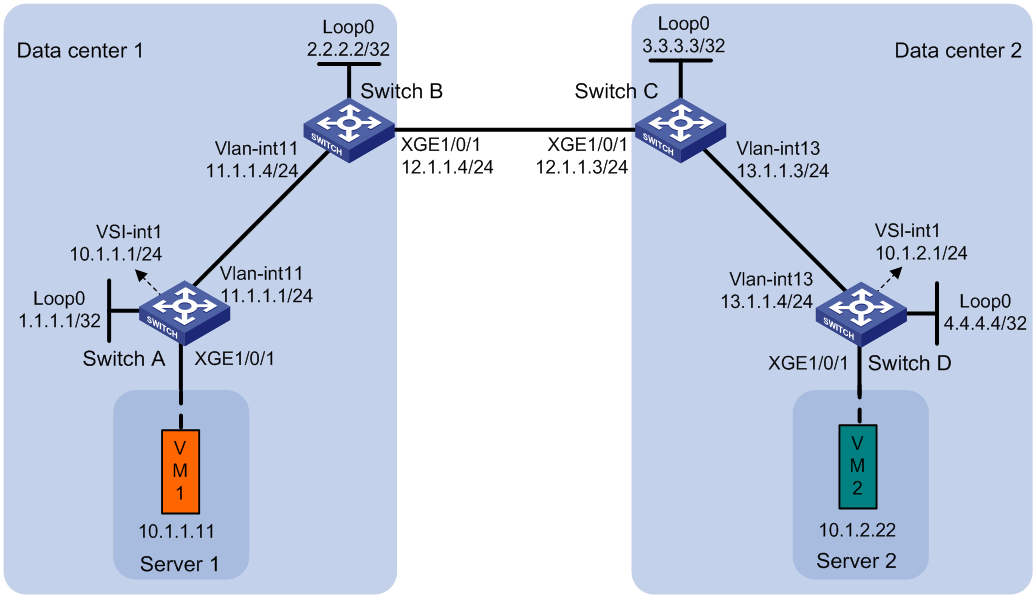
Procedure
1. Set the VXLAN hardware resource mode:
¡ S6800 and S6860 switch series:
# Set the VXLAN hardware resource mode on Switch A and Switch D and reboot the switches for the mode to take effect. This step uses Switch A as an example.
<SwitchA> system-view
[SwitchA] hardware-resource vxlan l3gw16k
Do you want to change the specified hardware resource working mode? [Y/N]:y
The hardware resource working mode is changed, please save the configuration and
reboot the system to make it effective.
[SwitchA] quit
<SwitchA> reboot
Start to check configuration with next startup configuration file, please wait..
.......DONE!
Current configuration may be lost after the reboot, save current configuration?
[Y/N]:y
This command will reboot the device. Continue? [Y/N]:y
# Set the VXLAN hardware resource mode on Switch B and Switch C and reboot the switches for the mode to take effect. This step uses Switch B as an example.
<SwitchB> system-view
[SwitchB] hardware-resource vxlan border24k
Do you want to change the specified hardware resource working mode? [Y/N]:y
The hardware resource working mode is changed, please save the configuration and
reboot the system to make it effective.
[SwitchB] quit
<SwitchB> reboot
Start to check configuration with next startup configuration file, please wait..
.......DONE!
Current configuration may be lost after the reboot, save current configuration?
[Y/N]:y
This command will reboot the device. Continue? [Y/N]:y
¡ S6820 switch series:
# Set the VXLAN hardware resource mode to l3gw or border on Switch A and Switch D and reboot the switches for the mode to take effect. (Details not shown.)
# Set the VXLAN hardware resource mode on Switch B and Switch C and reboot the switches for the mode to take effect. This step uses Switch B as an example.
<SwitchB> system-view
[SwitchB] hardware-resource vxlan border
Do you want to change the specified hardware resource working mode? [Y/N]:y
The hardware resource working mode is changed, please save the configuration and
reboot the system to make it effective.
[SwitchB] quit
<SwitchB> reboot
Start to check configuration with next startup configuration file, please wait..
.......DONE!
Current configuration may be lost after the reboot, save current configuration?
[Y/N]:y
This command will reboot the device. Continue? [Y/N]:y
2. Configure IP addresses and unicast routing settings:
# On VM 1, specify 10.1.1.1 as the gateway address. On VM 2, specify 10.1.2.1 as the gateway address. (Details not shown.)
# Assign IP addresses to interfaces, as shown in Figure 33. (Details not shown.)
# Configure OSPF on the transport network for the switches to reach one another. (Details not shown.)
3. Configure Switch A:
# Enable L2VPN.
<SwitchA> system-view
[SwitchA] l2vpn enable
# (S6820 switch series.) Reserve the global VLAN interface resources of VLAN 3000 and VLAN 3001.
[SwitchA] reserve-vlan-interface 3000 to 3001 global
# (S6820-32H and S6820-4C switches.) Create VSI gateway service loopback group 1, and assign Layer 2 Ethernet interface Ten-GigabitEthernet 1/0/4 to the service loopback group.
[SwitchA] service-loopback group 1 type vsi-gateway
[SwitchA] interface ten-gigabitethernet 1/0/4
[SwitchA-Ten-GigabitEthernet1/0/4] port service-loopback group 1
All configurations on the interface will be lost. Continue?[Y/N]:y
[SwitchA-Ten-GigabitEthernet1/0/4] quit
# Disable remote MAC address learning and remote ARP learning.
[SwitchA] vxlan tunnel mac-learning disable
[SwitchA] vxlan tunnel arp-learning disable
# Create VXLAN 10 on VSI vpna.
[SwitchA] vsi vpna
[SwitchA-vsi-vpna] vxlan 10
[SwitchA-vsi-vpna-vxlan-10] quit
# Create an EVPN instance on VSI vpna. Configure the switch to automatically generate an RD and a route target for the EVPN instance.
[SwitchA-vsi-vpna] evpn encapsulation vxlan
[SwitchA-vsi-vpna-evpn-vxlan] route-distinguisher auto
[SwitchA-vsi-vpna-evpn-vxlan] vpn-target auto
[SwitchA-vsi-vpna-evpn-vxlan] quit
[SwitchA-vsi-vpna] quit
# Configure BGP to advertise BGP EVPN routes.
[SwitchA] bgp 100
[SwitchA-bgp-default] peer 2.2.2.2 as-number 100
[SwitchA-bgp-default] peer 2.2.2.2 connect-interface loopback 0
[SwitchA-bgp-default] address-family l2vpn evpn
[SwitchA-bgp-default-evpn] peer 2.2.2.2 enable
[SwitchA-bgp-default-evpn] quit
[SwitchA-bgp-default] quit
# On Ten-GigabitEthernet 1/0/1, create Ethernet service instance 1000 to match VLAN 100.
[SwitchA] interface ten-gigabitethernet 1/0/1
[SwitchA-Ten-GigabitEthernet1/0/1] service-instance 1000
[SwitchA-Ten-GigabitEthernet1/0/1-srv1000] encapsulation s-vid 100
# Map Ethernet service instance 1000 to VSI vpna.
[SwitchA-Ten-GigabitEthernet1/0/1-srv1000] xconnect vsi vpna
[SwitchA-Ten-GigabitEthernet1/0/1-srv1000] quit
# Configure RD and route target settings for VPN instance vpn1.
[SwitchA] ip vpn-instance vpn1
[SwitchA-vpn-instance-vpn1] route-distinguisher 1:1
[SwitchA-vpn-instance-vpn1] address-family ipv4
[SwitchA-vpn-ipv4-vpn1] vpn-target 2:2
[SwitchA-vpn-ipv4-vpn1] quit
[SwitchA-vpn-instance-vpn1] address-family evpn
[SwitchA-vpn-evpn-vpn1] vpn-target 1:1
[SwitchA-vpn-evpn-vpn1] quit
[SwitchA-vpn-instance-vpn1] quit
# Configure VSI-interface 1 as a distributed gateway.
[SwitchA] interface vsi-interface 1
[SwitchA-Vsi-interface1] ip binding vpn-instance vpn1
[SwitchA-Vsi-interface1] ip address 10.1.1.1 255.255.255.0
[SwitchA-Vsi-interface1] mac-address 1-1-1
[SwitchA-Vsi-interface1] distributed-gateway local
[SwitchA-Vsi-interface1] quit
# Create VSI-interface 2. Associate VSI-interface 2 with VPN instance vpn1, and configure the L3 VXLAN ID as 1000 for the VPN instance.
[SwitchA] interface vsi-interface 2
[SwitchA-Vsi-interface2] ip binding vpn-instance vpn1
[SwitchA-Vsi-interface2] l3-vni 1000
[SwitchA-Vsi-interface2] quit
# Specify VSI-interface 1 as the gateway interface for VSI vpna.
[SwitchA] vsi vpna
[SwitchA-vsi-vpna] gateway vsi-interface 1
[SwitchA-vsi-vpna] quit
4. Configure Switch B:
# Enable L2VPN.
<SwitchB> system-view
[SwitchB] l2vpn enable
# (S6820 switch series.) Reserve the global VLAN interface resources of VLAN 3000 and VLAN 3001.
[SwitchB] reserve-vlan-interface 3000 to 3001 global
# (S6820-32H and S6820-4C switches.) Create VSI gateway service loopback group 1, and assign Layer 2 Ethernet interface Ten-GigabitEthernet 1/0/4 to the service loopback group.
[SwitchB] service-loopback group 1 type vsi-gateway
[SwitchB] interface ten-gigabitethernet 1/0/4
[SwitchB-Ten-GigabitEthernet1/0/4] port service-loopback group 1
All configurations on the interface will be lost. Continue?[Y/N]:y
[SwitchB-Ten-GigabitEthernet1/0/4] quit
# Disable remote MAC address learning and remote ARP learning.
[SwitchB] vxlan tunnel mac-learning disable
[SwitchB] vxlan tunnel arp-learning disable
# Enable DCI on the Layer 3 interface that connects Switch B to Switch C for the switches to establish a VXLAN-DCI tunnel.
[SwitchB] interface ten-gigabitethernet 1/0/1
[SwitchB-Ten-GigabitEthernet1/0/1] dci enable
[SwitchB-Ten-GigabitEthernet1/0/1] quit
# Configure BGP to advertise BGP EVPN routes. Enable nexthop replacement for routes advertised to Switch A, and enable router MAC replacement for routes advertised to and received from Switch C.
[SwitchB] bgp 100
[SwitchB-bgp-default] peer 3.3.3.3 as-number 200
[SwitchB-bgp-default] peer 3.3.3.3 connect-interface loopback 0
[SwitchB-bgp-default] peer 3.3.3.3 ebgp-max-hop 64
[SwitchB-bgp-default] peer 1.1.1.1 as-number 100
[SwitchB-bgp-default] peer 1.1.1.1 connect-interface loopback 0
[SwitchB-bgp-default] address-family l2vpn evpn
[SwitchB-bgp-default-evpn] peer 3.3.3.3 enable
[SwitchB-bgp-default-evpn] peer 3.3.3.3 router-mac-local
[SwitchB-bgp-default-evpn] peer 1.1.1.1 enable
[SwitchB-bgp-default-evpn] peer 1.1.1.1 next-hop-local
[SwitchB-bgp-default-evpn] quit
[SwitchB-bgp-default] quit
# Configure RD and route target settings for VPN instance vpn1.
[SwitchB] ip vpn-instance vpn1
[SwitchB-vpn-instance-vpn1] route-distinguisher 1:2
[SwitchB-vpn-instance-vpn1] address-family ipv4
[SwitchB-vpn-ipv4-vpn1] vpn-target 2:2
[SwitchB-vpn-ipv4-vpn1] quit
[SwitchB-vpn-instance-vpn1] address-family evpn
[SwitchB-vpn-evpn-vpn1] vpn-target 1:1
[SwitchB-vpn-evpn-vpn1] quit
[SwitchB-vpn-instance-vpn1] quit
# Create VSI-interface 2. Associate VSI-interface 2 with VPN instance vpn1, and configure the L3 VXLAN ID as 1000 for the VPN instance.
[SwitchB] interface vsi-interface 2
[SwitchB-Vsi-interface2] ip binding vpn-instance vpn1
[SwitchB-Vsi-interface2] l3-vni 1000
[SwitchB-Vsi-interface2] quit
5. Configure Switch C:
# Enable L2VPN.
<SwitchC> system-view
[SwitchC] l2vpn enable
# (S6820 switch series.) Reserve the global VLAN interface resources of VLAN 3000 and VLAN 3001.
[SwitchC] reserve-vlan-interface 3000 to 3001 global
# (S6820-32H and S6820-4C switches.) Create VSI gateway service loopback group 1, and assign Layer 2 Ethernet interface Ten-GigabitEthernet 1/0/4 to the service loopback group.
[SwitchC] service-loopback group 1 type vsi-gateway
[SwitchC] interface ten-gigabitethernet 1/0/4
[SwitchC-Ten-GigabitEthernet1/0/4] port service-loopback group 1
All configurations on the interface will be lost. Continue?[Y/N]:y
[SwitchC-Ten-GigabitEthernet1/0/4] quit
# Disable remote MAC address learning and remote ARP learning.
[SwitchC] vxlan tunnel mac-learning disable
[SwitchC] vxlan tunnel arp-learning disable
# Enable DCI on the Layer 3 interface that connects Switch C to Switch B for the switches to establish a VXLAN-DCI tunnel.
[SwitchC] interface ten-gigabitethernet 1/0/1
[SwitchC-Ten-GigabitEthernet1/0/1] dci enable
[SwitchC-Ten-GigabitEthernet1/0/1] quit
# Configure BGP to advertise BGP EVPN routes. Enable nexthop replacement for routes advertised to Switch D, and enable router MAC replacement for routes advertised to and received from Switch B.
[SwitchC] bgp 200
[SwitchC-bgp-default] peer 2.2.2.2 as-number 100
[SwitchC-bgp-default] peer 2.2.2.2 connect-interface Loopback 0
[SwitchC-bgp-default] peer 2.2.2.2 ebgp-max-hop 64
[SwitchC-bgp-default] peer 4.4.4.4 as-number 200
[SwitchC-bgp-default] peer 4.4.4.4 connect-interface Loopback 0
[SwitchC-bgp-default] address-family l2vpn evpn
[SwitchC-bgp-default-evpn] peer 2.2.2.2 enable
[SwitchC-bgp-default-evpn] peer 2.2.2.2 router-mac-local
[SwitchC-bgp-default-evpn] peer 4.4.4.4 enable
[SwitchC-bgp-default-evpn] peer 4.4.4.4 next-hop-local
[SwitchC-bgp-default-evpn] quit
[SwitchC-bgp-default] quit
# Configure RD and route target settings for VPN instance vpn1.
[SwitchC] ip vpn-instance vpn1
[SwitchC-vpn-instance-vpn1] route-distinguisher 1:3
[SwitchC-vpn-instance-vpn1] address-family ipv4
[SwitchC-vpn-ipv4-vpn1] vpn-target 2:2
[SwitchC-vpn-ipv4-vpn1] quit
[SwitchC-vpn-instance-vpn1] address-family evpn
[SwitchC-vpn-evpn-vpn1] vpn-target 1:1
[SwitchC-vpn-evpn-vpn1] quit
[SwitchC-vpn-instance-vpn1] quit
# Create VSI-interface 2. Associate VSI-interface 2 with VPN instance vpn1, and configure the L3 VXLAN ID as 1000 for the VPN instance.
[SwitchC] interface vsi-interface 2
[SwitchC-Vsi-interface2] ip binding vpn-instance vpn1
[SwitchC-Vsi-interface2] l3-vni 1000
[SwitchC-Vsi-interface2] quit
6. Configure Switch D:
# Enable L2VPN.
<SwitchD> system-view
[SwitchD] l2vpn enable
# (S6820 switch series.) Reserve the global VLAN interface resources of VLAN 3000 and VLAN 3001.
[SwitchD] reserve-vlan-interface 3000 to 3001 global
# (S6820-32H and S6820-4C switches.) Create VSI gateway service loopback group 1, and assign Layer 2 Ethernet interface Ten-GigabitEthernet 1/0/4 to the service loopback group.
[SwitchD] service-loopback group 1 type vsi-gateway
[SwitchD] interface ten-gigabitethernet 1/0/4
[SwitchD-Ten-GigabitEthernet1/0/4] port service-loopback group 1
All configurations on the interface will be lost. Continue?[Y/N]:y
[SwitchD-Ten-GigabitEthernet1/0/4] quit
# Disable remote MAC address learning and remote ARP learning.
[SwitchD] vxlan tunnel mac-learning disable
[SwitchD] vxlan tunnel arp-learning disable
# Create an EVPN instance on VSI vpnb. Configure the switch to automatically generate an RD and a route target for the EVPN instance.
[SwitchD] vsi vpnb
[SwitchD-vsi-vpnb] evpn encapsulation vxlan
[SwitchD-vsi-vpnb-evpn-vxlan] route-distinguisher auto
[SwitchD-vsi-vpnb-evpn-vxlan] vpn-target auto
[SwitchD-vsi-vpnb-evpn-vxlan] quit
# Create VXLAN 20 on VSI vpnb.
[SwitchD-vsi-vpnb] vxlan 20
[SwitchD-vsi-vpnb-vxlan-20] quit
[SwitchD-vsi-vpnb] quit
# Configure BGP to advertise BGP EVPN routes.
[SwitchD] bgp 200
[SwitchD-bgp-default] peer 3.3.3.3 as-number 200
[SwitchD-bgp-default] peer 3.3.3.3 connect-interface Loopback 0
[SwitchD-bgp-default] address-family l2vpn evpn
[SwitchD-bgp-default-evpn] peer 3.3.3.3 enable
[SwitchD-bgp-default-evpn] quit
[SwitchD-bgp-default] quit
# On Ten-GigabitEthernet 1/0/1, create Ethernet service instance 3000 to match VLAN 3.
[SwitchD] interface ten-gigabitethernet 1/0/1
[SwitchD-Ten-GigabitEthernet1/0/1] service-instance 3000
[SwitchD-Ten-GigabitEthernet1/0/1-srv3000] encapsulation s-vid 3
# Map Ethernet service instance 3000 to VSI vpnb.
[SwitchD-Ten-GigabitEthernet1/0/1-srv3000] xconnect vsi vpnb
[SwitchD-Ten-GigabitEthernet1/0/1-srv3000] quit
# Configure RD and route target settings for VPN instance vpn1.
[SwitchD] ip vpn-instance vpn1
[SwitchD-vpn-instance-vpn1] route-distinguisher 1:4
[SwitchD-vpn-instance-vpn1] address-family ipv4
[SwitchD-vpn-ipv4-vpn1] vpn-target 2:2
[SwitchD-vpn-ipv4-vpn1] quit
[SwitchD-vpn-instance-vpn1] address-family evpn
[SwitchD-vpn-evpn-vpn1] vpn-target 1:1
[SwitchD-vpn-evpn-vpn1] quit
[SwitchD-vpn-instance-vpn1] quit
# Configure VSI-interface 1 as a distributed gateway.
[SwitchD] interface vsi-interface 1
[SwitchD-Vsi-interface1] ip binding vpn-instance vpn1
[SwitchD-Vsi-interface1] ip address 10.1.2.1 255.255.255.0
[SwitchD-Vsi-interface1] mac-address 1-2-1
[SwitchD-Vsi-interface1] distributed-gateway local
[SwitchD-Vsi-interface1] quit
# Create VSI-interface 2. Associate VSI-interface 2 with VPN instance vpn1, and configure the L3 VXLAN ID as 1000 for the VPN instance.
[SwitchD] interface vsi-interface 2
[SwitchD-Vsi-interface2] ip binding vpn-instance vpn1
[SwitchD-Vsi-interface2] l3-vni 1000
[SwitchD-Vsi-interface2] quit
# Specify VSI-interface 1 as the gateway interface for VSI vpnb.
[SwitchD] vsi vpnb
[SwitchD-vsi-vpnb] gateway vsi-interface 1
[SwitchD-vsi-vpnb] quit
Verifying the configuration
1. Verify the configuration on EDs. (This example uses Switch B.)
# Verify that the ED has discovered Switch A and Switch C through MAC/IP advertisement routes and IP prefix advertisement routes, and has established VXLAN and VXLAN-DCI tunnels to the switches.
[SwitchB] display evpn auto-discovery macip-prefix
Destination IP Source IP L3VNI Tunnel mode OutgoingInterface
1.1.1.1 2.2.2.2 1000 VXLAN Vsi-interface2
3.3.3.3 2.2.2.2 1000 VXLAN-DCI Vsi-interface2
# Verify that the VXLAN and VXLAN-DCI tunnels on the ED are up.
[SwitchB] display interface tunnel
Tunnel0
Current state: UP
Line protocol state: UP
Description: Tunnel0 Interface
Bandwidth: 64 kbps
Maximum transmission unit: 1464
Internet protocol processing: Disabled
Last clearing of counters: Never
Tunnel source 2.2.2.2, destination 1.1.1.1
Tunnel protocol/transport UDP_VXLAN/IP
Last 300 seconds input rate: 0 bytes/sec, 0 bits/sec, 0 packets/sec
Last 300 seconds output rate: 0 bytes/sec, 0 bits/sec, 0 packets/sec
Input: 0 packets, 0 bytes, 0 drops
Output: 0 packets, 0 bytes, 0 drops
Tunnel1
Current state: UP
Line protocol state: UP
Description: Tunnel1 Interface
Bandwidth: 64 kbps
Maximum transmission unit: 1464
Internet protocol processing: Disabled
Last clearing of counters: Never
Tunnel source 2.2.2.2, destination 3.3.3.3
Tunnel protocol/transport UDP_VXLAN-DCI/IP
Last 300 seconds input rate: 0 bytes/sec, 0 bits/sec, 0 packets/sec
Last 300 seconds output rate: 0 bytes/sec, 0 bits/sec, 0 packets/sec
Input: 0 packets, 0 bytes, 0 drops
Output: 0 packets, 0 bytes, 0 drops
# Verify that the ED has ARP entries and routes for the VMs.
[SwitchB] display arp vpn-instance vpn1
Type: S Type: S-Static D-Dynamic O-Openflow R-Rule M-Multiport I-Invalid
IP address MAC address VLAN/VSI Interface/Link ID Aging Type
1.1.1.1 0031-1900-0000 0 Tunnel0 -- R
3.3.3.3 0031-3900-0000 0 Tunnel1 -- R
[SwitchB] display ip routing-table vpn-instance vpn1
Destinations : 4 Routes : 4
Destination/Mask Proto Pre Cost NextHop Interface
10.1.1.0/24 BGP 255 0 1.1.1.1 Vsi2
10.1.1.11/32 BGP 255 0 1.1.1.1 Vsi2
10.1.2.0/24 BGP 255 0 3.3.3.3 Vsi2
10.1.2.22/32 BGP 255 0 3.3.3.3 Vsi2
2. Verify that VM 1 and VM 2 can communicate. (Details not shown.)
Example: Configuring EVPN-DCI Layer 3 communication (IPv6 sites+IPv4 underlay network)
Network configuration
As shown in Figure 34:
· Configure VXLAN 10 for data center 1, and configure VXLAN 20 for data center 2.
· Configure Switch A and Switch D as distributed EVPN gateways to perform Layer 3 forwarding between VXLAN 10 and VXLAN 20.
· Configure Switch B and Switch C as EDs.
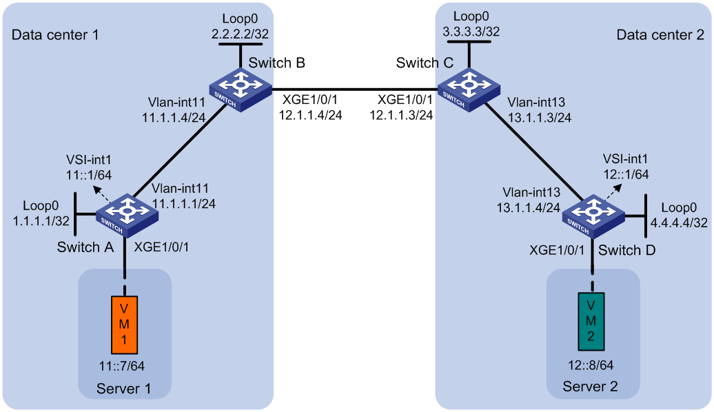
Procedure
1. Set the VXLAN hardware resource mode:
¡ S6800 and S6860 switch series:
# Set the VXLAN hardware resource mode on Switch A and Switch D and reboot the switches for the mode to take effect. This step uses Switch A as an example.
<SwitchA> system-view
[SwitchA] hardware-resource vxlan l3gw16k
Do you want to change the specified hardware resource working mode? [Y/N]:y
The hardware resource working mode is changed, please save the configuration and
reboot the system to make it effective.
[SwitchA] quit
<SwitchA> reboot
Start to check configuration with next startup configuration file, please wait..
.......DONE!
Current configuration may be lost after the reboot, save current configuration?
[Y/N]:y
This command will reboot the device. Continue? [Y/N]:y
# Set the VXLAN hardware resource mode on Switch B and Switch C and reboot the switches for the mode to take effect. This step uses Switch B as an example.
<SwitchB> system-view
[SwitchB] hardware-resource vxlan border24k
Do you want to change the specified hardware resource working mode? [Y/N]:y
The hardware resource working mode is changed, please save the configuration and
reboot the system to make it effective.
[SwitchB] quit
<SwitchB> reboot
Start to check configuration with next startup configuration file, please wait..
.......DONE!
Current configuration may be lost after the reboot, save current configuration?
[Y/N]:y
This command will reboot the device. Continue? [Y/N]:y
¡ S6820 switch series:
# Set the VXLAN hardware resource mode to l3gw or border on Switch A and Switch D and reboot the switches for the mode to take effect. (Details not shown.)
# Set the VXLAN hardware resource mode on Switch B and Switch C and reboot the switches for the mode to take effect. This step uses Switch B as an example.
<SwitchB> system-view
[SwitchB] hardware-resource vxlan border
Do you want to change the specified hardware resource working mode? [Y/N]:y
The hardware resource working mode is changed, please save the configuration and
reboot the system to make it effective.
[SwitchB] quit
<SwitchB> reboot
Start to check configuration with next startup configuration file, please wait..
.......DONE!
Current configuration may be lost after the reboot, save current configuration?
[Y/N]:y
This command will reboot the device. Continue? [Y/N]:y
2. Configure IP addresses and unicast routing settings:
# On VM 1, specify 11::1 as the gateway address. On VM 2, specify 12::1 as the gateway address. (Details not shown.)
# Assign IP addresses to interfaces, as shown in Figure 34. (Details not shown.)
# Configure OSPF on the transport network for the switches to reach one another. (Details not shown.)
3. Configure Switch A:
# Enable L2VPN.
<SwitchA> system-view
[SwitchA] l2vpn enable
# (S6820 switch series.) Reserve the global VLAN interface resources of VLAN 3000 and VLAN 3001.
[SwitchA] reserve-vlan-interface 3000 to 3001 global
# (S6820-32H and S6820-4C switches.) Create VSI gateway service loopback group 1, and assign Layer 2 Ethernet interface Ten-GigabitEthernet 1/0/4 to the service loopback group.
[SwitchA] service-loopback group 1 type vsi-gateway
[SwitchA] interface ten-gigabitethernet 1/0/4
[SwitchA-Ten-GigabitEthernet1/0/4] port service-loopback group 1
All configurations on the interface will be lost. Continue?[Y/N]:y
[SwitchA-Ten-GigabitEthernet1/0/4] quit
# Disable remote MAC address learning and remote ND learning.
[SwitchA] vxlan tunnel mac-learning disable
[SwitchA] vxlan tunnel nd-learning disable
# Create VXLAN 10 on VSI vpna.
[SwitchA] vsi vpna
[SwitchA-vsi-vpna] vxlan 10
[SwitchA-vsi-vpna-vxlan-10] quit
# Create an EVPN instance on VSI vpna. Configure the switch to automatically generate an RD and a route target for the EVPN instance.
[SwitchA-vsi-vpna] evpn encapsulation vxlan
[SwitchA-vsi-vpna-evpn-vxlan] route-distinguisher auto
[SwitchA-vsi-vpna-evpn-vxlan] vpn-target auto
[SwitchA-vsi-vpna-evpn-vxlan] quit
[SwitchA-vsi-vpna] quit
# Configure BGP to advertise BGP EVPN routes.
[SwitchA] bgp 100
[SwitchA-bgp-default] peer 2.2.2.2 as-number 100
[SwitchA-bgp-default] peer 2.2.2.2 connect-interface loopback 0
[SwitchA-bgp-default] address-family l2vpn evpn
[SwitchA-bgp-default-evpn] peer 2.2.2.2 enable
[SwitchA-bgp-default-evpn] quit
[SwitchA-bgp-default] quit
# On Ten-GigabitEthernet 1/0/1, create Ethernet service instance 1000 to match VLAN 100.
[SwitchA] interface ten-gigabitethernet 1/0/1
[SwitchA-Ten-GigabitEthernet1/0/1] service-instance 1000
[SwitchA-Ten-GigabitEthernet1/0/1-srv1000] encapsulation s-vid 100
# Map Ethernet service instance 1000 to VSI vpna.
[SwitchA-Ten-GigabitEthernet1/0/1-srv1000] xconnect vsi vpna
[SwitchA-Ten-GigabitEthernet1/0/1-srv1000] quit
# Configure RD and route target settings for VPN instance vpn1.
[SwitchA] ip vpn-instance vpn1
[SwitchA-vpn-instance-vpn1] route-distinguisher 1:1
[SwitchA-vpn-instance-vpn1] address-family ipv6
[SwitchA-vpn-ipv6-vpn1] vpn-target 2:2
[SwitchA-vpn-ipv6-vpn1] quit
[SwitchA-vpn-instance-vpn1] address-family evpn
[SwitchA-vpn-evpn-vpn1] vpn-target 1:1
[SwitchA-vpn-evpn-vpn1] quit
[SwitchA-vpn-instance-vpn1] quit
# Configure VSI-interface 1 as a distributed gateway.
[SwitchA] interface vsi-interface 1
[SwitchA-Vsi-interface1] ip binding vpn-instance vpn1
[SwitchA-Vsi-interface1] ipv6 address 11::1 64
[SwitchA-Vsi-interface1] mac-address 1-1-1
[SwitchA-Vsi-interface1] distributed-gateway local
[SwitchA-Vsi-interface1] quit
# Create VSI-interface 2. Associate VSI-interface 2 with VPN instance vpn1, and configure the L3 VXLAN ID as 1000 for the VPN instance.
[SwitchA] interface vsi-interface 2
[SwitchA-Vsi-interface2] ip binding vpn-instance vpn1
[SwitchA-Vsi-interface2] ipv6 address auto link-local
[SwitchA-Vsi-interface2] l3-vni 1000
[SwitchA-Vsi-interface2] quit
# Specify VSI-interface 1 as the gateway interface for VSI vpna.
[SwitchA] vsi vpna
[SwitchA-vsi-vpna] gateway vsi-interface 1
[SwitchA-vsi-vpna] quit
4. Configure Switch B:
# Enable L2VPN.
<SwitchB> system-view
[SwitchB] l2vpn enable
# (S6820 switch series.) Reserve the global VLAN interface resources of VLAN 3000 and VLAN 3001.
[SwitchB] reserve-vlan-interface 3000 to 3001 global
# (S6820-32H and S6820-4C switches.) Create VSI gateway service loopback group 1, and assign Layer 2 Ethernet interface Ten-GigabitEthernet 1/0/4 to the service loopback group.
[SwitchB] service-loopback group 1 type vsi-gateway
[SwitchB] interface ten-gigabitethernet 1/0/4
[SwitchB-Ten-GigabitEthernet1/0/4] port service-loopback group 1
All configurations on the interface will be lost. Continue?[Y/N]:y
[SwitchB-Ten-GigabitEthernet1/0/4] quit
# Disable remote MAC address learning and remote ND learning.
[SwitchB] vxlan tunnel mac-learning disable
[SwitchB] vxlan tunnel nd-learning disable
# Enable DCI on the Layer 3 interface that connects Switch B to Switch C for the switches to establish a VXLAN-DCI tunnel.
[SwitchB] interface ten-gigabitethernet 1/0/1
[SwitchB-Ten-GigabitEthernet1/0/1] dci enable
[SwitchB-Ten-GigabitEthernet1/0/1] quit
# Configure BGP to advertise BGP EVPN routes. Enable nexthop replacement for routes advertised to Switch A, and enable router MAC replacement for routes advertised to and received from Switch C.
[SwitchB] bgp 100
[SwitchB-bgp-default] peer 3.3.3.3 as-number 200
[SwitchB-bgp-default] peer 3.3.3.3 connect-interface loopback 0
[SwitchB-bgp-default] peer 3.3.3.3 ebgp-max-hop 64
[SwitchB-bgp-default] peer 1.1.1.1 as-number 100
[SwitchB-bgp-default] peer 1.1.1.1 connect-interface loopback 0
[SwitchB-bgp-default] address-family l2vpn evpn
[SwitchB-bgp-default-evpn] peer 3.3.3.3 enable
[SwitchB-bgp-default-evpn] peer 3.3.3.3 router-mac-local
[SwitchB-bgp-default-evpn] peer 1.1.1.1 enable
[SwitchB-bgp-default-evpn] peer 1.1.1.1 next-hop-local
[SwitchB-bgp-default-evpn] quit
[SwitchB-bgp-default] quit
# Configure RD and route target settings for VPN instance vpn1.
[SwitchB] ip vpn-instance vpn1
[SwitchB-vpn-instance-vpn1] route-distinguisher 1:2
[SwitchB-vpn-instance-vpn1] address-family ipv6
[SwitchB-vpn-ipv6-vpn1] vpn-target 2:2
[SwitchB-vpn-ipv6-vpn1] quit
[SwitchB-vpn-instance-vpn1] address-family evpn
[SwitchB-vpn-evpn-vpn1] vpn-target 1:1
[SwitchB-vpn-evpn-vpn1] quit
[SwitchB-vpn-instance-vpn1] quit
# Create VSI-interface 2. Associate VSI-interface 2 with VPN instance vpn1, and configure the L3 VXLAN ID as 1000 for the VPN instance.
[SwitchB] interface vsi-interface 2
[SwitchB-Vsi-interface2] ip binding vpn-instance vpn1
[SwitchB-Vsi-interface2] ipv6 address auto link-local
[SwitchB-Vsi-interface2] l3-vni 1000
[SwitchB-Vsi-interface2] quit
5. Configure Switch C:
# Enable L2VPN.
<SwitchC> system-view
[SwitchC] l2vpn enable
# (S6820 switch series.) Reserve the global VLAN interface resources of VLAN 3000 and VLAN 3001.
[SwitchC] reserve-vlan-interface 3000 to 3001 global
# (S6820-32H and S6820-4C switches.) Create VSI gateway service loopback group 1, and assign Layer 2 Ethernet interface Ten-GigabitEthernet 1/0/4 to the service loopback group.
[SwitchC] service-loopback group 1 type vsi-gateway
[SwitchC] interface ten-gigabitethernet 1/0/4
[SwitchC-Ten-GigabitEthernet1/0/4] port service-loopback group 1
All configurations on the interface will be lost. Continue?[Y/N]:y
[SwitchC-Ten-GigabitEthernet1/0/4] quit
# Disable remote MAC address learning and remote ND learning.
[SwitchC] vxlan tunnel mac-learning disable
[SwitchC] vxlan tunnel nd-learning disable
# Enable DCI on the Layer 3 interface that connects Switch C to Switch B for the switches to establish a VXLAN-DCI tunnel.
[SwitchC] interface ten-gigabitethernet 1/0/1
[SwitchC-Ten-GigabitEthernet1/0/1] dci enable
[SwitchC-Ten-GigabitEthernet1/0/1] quit
# Configure BGP to advertise BGP EVPN routes. Enable nexthop replacement for routes advertised to Switch D, and enable router MAC replacement for routes advertised to and received from Switch B.
[SwitchC] bgp 200
[SwitchC-bgp-default] peer 2.2.2.2 as-number 100
[SwitchC-bgp-default] peer 2.2.2.2 connect-interface Loopback 0
[SwitchC-bgp-default] peer 2.2.2.2 ebgp-max-hop 64
[SwitchC-bgp-default] peer 4.4.4.4 as-number 200
[SwitchC-bgp-default] peer 4.4.4.4 connect-interface Loopback 0
[SwitchC-bgp-default] address-family l2vpn evpn
[SwitchC-bgp-default-evpn] peer 2.2.2.2 enable
[SwitchC-bgp-default-evpn] peer 2.2.2.2 router-mac-local
[SwitchC-bgp-default-evpn] peer 4.4.4.4 enable
[SwitchC-bgp-default-evpn] peer 4.4.4.4 next-hop-local
[SwitchC-bgp-default-evpn] quit
[SwitchC-bgp-default] quit
# Configure RD and route target settings for VPN instance vpn1.
[SwitchC] ip vpn-instance vpn1
[SwitchC-vpn-instance-vpn1] route-distinguisher 1:3
[SwitchC-vpn-instance-vpn1] address-family ipv6
[SwitchC-vpn-ipv6-vpn1] vpn-target 2:2
[SwitchC-vpn-ipv6-vpn1] quit
[SwitchC-vpn-instance-vpn1] address-family evpn
[SwitchC-vpn-evpn-vpn1] vpn-target 1:1
[SwitchC-vpn-evpn-vpn1] quit
[SwitchC-vpn-instance-vpn1] quit
# Create VSI-interface 2. Associate VSI-interface 2 with VPN instance vpn1, and configure the L3 VXLAN ID as 1000 for the VPN instance.
[SwitchC] interface vsi-interface 2
[SwitchC-Vsi-interface2] ip binding vpn-instance vpn1
[SwitchC-Vsi-interface2] ipv6 address auto link-local
[SwitchC-Vsi-interface2] l3-vni 1000
[SwitchC-Vsi-interface2] quit
6. Configure Switch D:
# Enable L2VPN.
<SwitchD> system-view
[SwitchD] l2vpn enable
# (S6820 switch series.) Reserve the global VLAN interface resources of VLAN 3000 and VLAN 3001.
[SwitchD] reserve-vlan-interface 3000 to 3001 global
# (S6820-32H and S6820-4C switches.) Create VSI gateway service loopback group 1, and assign Layer 2 Ethernet interface Ten-GigabitEthernet 1/0/4 to the service loopback group.
[SwitchD] service-loopback group 1 type vsi-gateway
[SwitchD] interface ten-gigabitethernet 1/0/4
[SwitchD-Ten-GigabitEthernet1/0/4] port service-loopback group 1
All configurations on the interface will be lost. Continue?[Y/N]:y
[SwitchD-Ten-GigabitEthernet1/0/4] quit
# Disable remote MAC address learning and remote ND learning.
[SwitchD] vxlan tunnel mac-learning disable
[SwitchD] vxlan tunnel nd-learning disable
# Create an EVPN instance on VSI vpnb. Configure the switch to automatically generate an RD and a route target for the EVPN instance.
[SwitchD] vsi vpnb
[SwitchD-vsi-vpnb] evpn encapsulation vxlan
[SwitchD-vsi-vpnb-evpn-vxlan] route-distinguisher auto
[SwitchD-vsi-vpnb-evpn-vxlan] vpn-target auto
[SwitchD-vsi-vpnb-evpn-vxlan] quit
# Create VXLAN 20 on VSI vpnb.
[SwitchD-vsi-vpnb] vxlan 20
[SwitchD-vsi-vpnb-vxlan-20] quit
[SwitchD-vsi-vpnb] quit
# Configure BGP to advertise BGP EVPN routes.
[SwitchD] bgp 200
[SwitchD-bgp-default] peer 3.3.3.3 as-number 200
[SwitchD-bgp-default] peer 3.3.3.3 connect-interface Loopback 0
[SwitchD-bgp-default] address-family l2vpn evpn
[SwitchD-bgp-default-evpn] peer 3.3.3.3 enable
[SwitchD-bgp-default-evpn] quit
[SwitchD-bgp-default] quit
# On Ten-GigabitEthernet 1/0/1, create Ethernet service instance 3000 to match VLAN 3.
[SwitchD] interface ten-gigabitethernet 1/0/1
[SwitchD-Ten-GigabitEthernet1/0/1] service-instance 3000
[SwitchD-Ten-GigabitEthernet1/0/1-srv3000] encapsulation s-vid 3
# Map Ethernet service instance 3000 to VSI vpnb.
[SwitchD-Ten-GigabitEthernet1/0/1-srv3000] xconnect vsi vpnb
[SwitchD-Ten-GigabitEthernet1/0/1-srv3000] quit
# Configure RD and route target settings for VPN instance vpn1.
[SwitchD] ip vpn-instance vpn1
[SwitchD-vpn-instance-vpn1] route-distinguisher 1:4
[SwitchD-vpn-instance-vpn1] address-family ipv6
[SwitchD-vpn-ipv6-vpn1] vpn-target 2:2
[SwitchD-vpn-ipv6-vpn1] quit
[SwitchD-vpn-instance-vpn1] address-family evpn
[SwitchD-vpn-evpn-vpn1] vpn-target 1:1
[SwitchD-vpn-evpn-vpn1] quit
[SwitchD-vpn-instance-vpn1] quit
# Configure VSI-interface 1 as a distributed gateway.
[SwitchD] interface vsi-interface 1
[SwitchD-Vsi-interface1] ip binding vpn-instance vpn1
[SwitchD-Vsi-interface1] ipv6 address 12::1 64
[SwitchD-Vsi-interface1] mac-address 1-2-1
[SwitchD-Vsi-interface1] distributed-gateway local
[SwitchD-Vsi-interface1] quit
# Create VSI-interface 2. Associate VSI-interface 2 with VPN instance vpn1, and configure the L3 VXLAN ID as 1000 for the VPN instance.
[SwitchD] interface vsi-interface 2
[SwitchD-Vsi-interface2] ip binding vpn-instance vpn1
[SwitchD-Vsi-interface2] ipv6 address auto link-local
[SwitchD-Vsi-interface2] l3-vni 1000
[SwitchD-Vsi-interface2] quit
# Specify VSI-interface 1 as the gateway interface for VSI vpnb.
[SwitchD] vsi vpnb
[SwitchD-vsi-vpnb] gateway vsi-interface 1
[SwitchD-vsi-vpnb] quit
Verifying the configuration
1. Verify the configuration on EDs. (This example uses Switch B.)
# Verify that the ED has discovered Switch A and Switch C through MAC/IP advertisement routes and IP prefix advertisement routes, and has established VXLAN and VXLAN-DCI tunnels to the switches.
[SwitchB] display evpn auto-discovery macip-prefix
Destination IP Source IP L3VNI Tunnel mode OutInterface
1.1.1.1 2.2.2.2 1000 VXLAN Vsi-interface2
3.3.3.3 2.2.2.2 1000 VXLAN-DCI Vsi-interface2
# Verify that the VXLAN and VXLAN-DCI tunnels on the ED are up.
[SwitchB] display interface tunnel
Tunnel0
Current state: UP
Line protocol state: UP
Description: Tunnel0 Interface
Bandwidth: 64 kbps
Maximum transmission unit: 1464
Internet protocol processing: Disabled
Last clearing of counters: Never
Tunnel source 2.2.2.2, destination 1.1.1.1
Tunnel protocol/transport UDP_VXLAN/IP
Last 300 seconds input rate: 0 bytes/sec, 0 bits/sec, 0 packets/sec
Last 300 seconds output rate: 0 bytes/sec, 0 bits/sec, 0 packets/sec
Input: 0 packets, 0 bytes, 0 drops
Output: 0 packets, 0 bytes, 0 drops
Tunnel1
Current state: UP
Line protocol state: UP
Description: Tunnel1 Interface
Bandwidth: 64 kbps
Maximum transmission unit: 1464
Internet protocol processing: Disabled
Last clearing of counters: Never
Tunnel source 2.2.2.2, destination 3.3.3.3
Tunnel protocol/transport UDP_VXLAN-DCI/IP
Last 300 seconds input rate: 0 bytes/sec, 0 bits/sec, 0 packets/sec
Last 300 seconds output rate: 0 bytes/sec, 0 bits/sec, 0 packets/sec
Input: 0 packets, 0 bytes, 0 drops
Output: 0 packets, 0 bytes, 0 drops
# Verify that the ED has routes for the VMs.
[SwitchB] display ipv6 routing-table vpn-instance vpn1
Destinations : 7 Routes : 7
Destination: ::1/128 Protocol : Direct
NextHop : ::1 Preference: 0
Interface : InLoop0 Cost : 0
Destination: 10::/64 Protocol : BGP4+
NextHop : 1::1 Preference: 255
Interface : Vsi2 Cost : 0
Destination: 10::11/128 Protocol : BGP4+
NextHop : 1::1 Preference: 255
Interface : Vsi2 Cost : 0
Destination: 20::/64 Protocol : BGP4+
NextHop : 3::3 Preference: 255
Interface : Vsi2 Cost : 0
Destination: 20::22/128 Protocol : BGP4+
NextHop : 3::3 Preference: 255
Interface : Vsi2 Cost : 0
Destination: FE80::/10 Protocol : Direct
NextHop : :: Preference: 0
Interface : InLoop0 Cost : 0
Destination: FF00::/8 Protocol : Direct
NextHop : :: Preference: 0
Interface : NULL0
2. Verify that VM 1 and VM 2 can communicate. (Details not shown.)
Example: Configuring EVPN-DCI dual-homing (IPv4 sites+IPv4 underlay network)
Network configuration
As shown in Figure 35:
· Configure VXLAN 10 for data center 1, and configure VXLAN 20 for data center 2.
· Configure Switch A and Switch G as distributed EVPN gateways to perform Layer 3 forwarding between VXLAN 10 and VXLAN 20.
· Configure Switch C and Switch D as EDs of data center 1, and configure Switch F as the ED of data center 2.
· Configure Switch B as an RR.
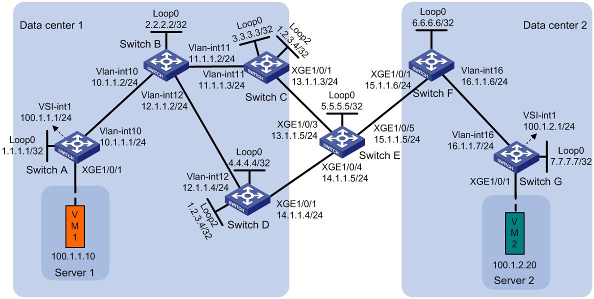
Procedure
1. Set the VXLAN hardware resource mode:
¡ S6800 and S6860 switch series:
# Set the VXLAN hardware resource mode on Switch A and Switch G and reboot the switches for the mode to take effect. This step uses Switch A as an example.
<SwitchA> system-view
[SwitchA] hardware-resource vxlan l3gw16k
Do you want to change the specified hardware resource working mode? [Y/N]:y
The hardware resource working mode is changed, please save the configuration and
reboot the system to make it effective.
[SwitchA] quit
<SwitchA> reboot
Start to check configuration with next startup configuration file, please wait..
.......DONE!
Current configuration may be lost after the reboot, save current configuration?
[Y/N]:y
This command will reboot the device. Continue? [Y/N]:y
# Set the VXLAN hardware resource mode on Switch C, Switch D, and Switch F and reboot the switches for the mode to take effect. This step uses Switch C as an example.
<SwitchC> system-view
[SwitchC] hardware-resource vxlan border24k
Do you want to change the specified hardware resource working mode? [Y/N]:y
The hardware resource working mode is changed, please save the configuration and
reboot the system to make it effective.
[SwitchC] quit
<SwitchC> reboot
Start to check configuration with next startup configuration file, please wait..
.......DONE!
Current configuration may be lost after the reboot, save current configuration?
[Y/N]:y
This command will reboot the device. Continue? [Y/N]:y
¡ S6820 switch series:
# Set the VXLAN hardware resource mode to l3gw or border on Switch A and Switch G and reboot the switches for the mode to take effect. (Details not shown.)
# Set the VXLAN hardware resource mode on Switch C, Switch D, and Switch F and reboot the switches for the mode to take effect. This step uses Switch C as an example.
<SwitchC> system-view
[SwitchC] hardware-resource vxlan border
Do you want to change the specified hardware resource working mode? [Y/N]:y
The hardware resource working mode is changed, please save the configuration and
reboot the system to make it effective.
[SwitchC] quit
<SwitchC> reboot
Start to check configuration with next startup configuration file, please wait..
.......DONE!
Current configuration may be lost after the reboot, save current configuration?
[Y/N]:y
This command will reboot the device. Continue? [Y/N]:y
2. Configure IP addresses and unicast routing settings:
# On VM 1, specify 100.1.1.1 as the gateway address. On VM 2, specify 100.1.2.1 as the gateway address. (Details not shown.)
# Assign IP addresses to the interfaces, as shown in Figure 35. (Details not shown.)
# Configure OSPF for the switches to reach one another. (Details not shown.)
3. Configure Switch A:
# Enable L2VPN.
<SwitchA> system-view
[SwitchA] l2vpn enable
# (S6820 switch series.) Reserve the global VLAN interface resources of VLAN 3000 and VLAN 3001.
[SwitchA] reserve-vlan-interface 3000 to 3001 global
# (S6820-32H and S6820-4C switches.) Create VSI gateway service loopback group 1, and assign Layer 2 Ethernet interface Ten-GigabitEthernet 1/0/4 to the service loopback group.
[SwitchA] service-loopback group 1 type vsi-gateway
[SwitchA] interface ten-gigabitethernet 1/0/4
[SwitchA-Ten-GigabitEthernet1/0/4] port service-loopback group 1
All configurations on the interface will be lost. Continue?[Y/N]:y
[SwitchA-Ten-GigabitEthernet1/0/4] quit
# Disable remote MAC address learning and remote ARP learning.
[SwitchA] vxlan tunnel mac-learning disable
[SwitchA] vxlan tunnel arp-learning disable
# Create VXLAN 10 on VSI vpna.
[SwitchA] vsi vpna
[SwitchA-vsi-vpna] vxlan 10
[SwitchA-vsi-vpna-vxlan-10] quit
# Create an EVPN instance on VSI vpna. Configure the switch to automatically generate an RD and a route target for the EVPN instance.
[SwitchA-vsi-vpna] evpn encapsulation vxlan
[SwitchA-vsi-vpna-evpn-vxlan] route-distinguisher auto
[SwitchA-vsi-vpna-evpn-vxlan] vpn-target auto
[SwitchA-vsi-vpna-evpn-vxlan] quit
[SwitchA-vsi-vpna] quit
# Configure BGP to advertise BGP EVPN routes.
[SwitchA] bgp 100
[SwitchA-bgp-default] peer 2.2.2.2 as-number 100
[SwitchA-bgp-default] peer 2.2.2.2 connect-interface loopback 0
[SwitchA-bgp-default] address-family l2vpn evpn
[SwitchA-bgp-default-evpn] peer 2.2.2.2 enable
[SwitchA-bgp-default-evpn] quit
[SwitchA-bgp-default] quit
# On Ten-GigabitEthernet 1/0/1, create Ethernet service instance 1000 to match VLAN 100.
[SwitchA] interface ten-gigabitethernet 1/0/1
[SwitchA-Ten-GigabitEthernet1/0/1] service-instance 1000
[SwitchA-Ten-GigabitEthernet1/0/1-srv1000] encapsulation s-vid 100
# Map Ethernet service instance 1000 to VSI vpna.
[SwitchA-Ten-GigabitEthernet1/0/1-srv1000] xconnect vsi vpna
[SwitchA-Ten-GigabitEthernet1/0/1-srv1000] quit
# Configure RD and route target settings for VPN instance vpn1.
[SwitchA] ip vpn-instance vpn1
[SwitchA-vpn-instance-vpn1] route-distinguisher 1:1
[SwitchA-vpn-instance-vpn1] address-family ipv4
[SwitchA-vpn-ipv4-vpn1] vpn-target 2:2
[SwitchA-vpn-ipv4-vpn1] quit
[SwitchA-vpn-instance-vpn1] address-family evpn
[SwitchA-vpn-evpn-vpn1] vpn-target 1:1
[SwitchA-vpn-evpn-vpn1] quit
[SwitchA-vpn-instance-vpn1] quit
# Configure VSI-interface 1 as a distributed gateway.
[SwitchA] interface vsi-interface 1
[SwitchA-Vsi-interface1] ip binding vpn-instance vpn1
[SwitchA-Vsi-interface1] ip address 100.1.1.1 255.255.255.0
[SwitchA-Vsi-interface1] mac-address 1-1-1
[SwitchA-Vsi-interface1] distributed-gateway local
[SwitchA-Vsi-interface1] quit
# Create VSI-interface 2. Associate VSI-interface 2 with VPN instance vpn1, and configure the L3 VXLAN ID as 1000 for the VPN instance.
[SwitchA] interface vsi-interface 2
[SwitchA-Vsi-interface2] ip binding vpn-instance vpn1
[SwitchA-Vsi-interface2] l3-vni 1000
[SwitchA-Vsi-interface2] quit
# Specify VSI-interface 1 as the gateway interface for VSI vpna.
[SwitchA] vsi vpna
[SwitchA-vsi-vpna] gateway vsi-interface 1
[SwitchA-vsi-vpna] quit
4. Configure Switch B as an RR.
<SwitchB> system-view
[SwitchB] bgp 100
[SwitchB-bgp-default] group evpn internal
[SwitchB-bgp-default] peer evpn connect-interface loopback 0
[SwitchB-bgp-default] peer 1.1.1.1 group evpn
[SwitchB-bgp-default] peer 3.3.3.3 group evpn
[SwitchB-bgp-default] peer 4.4.4.4 group evpn
[SwitchB-bgp-default] address-family l2vpn evpn
[SwitchB-bgp-default-evpn] undo policy vpn-target
[SwitchB-bgp-default-evpn] peer evpn enable
[SwitchB-bgp-default-evpn] peer evpn reflect-client
[SwitchB-bgp-default-evpn] quit
5. Configure Switch C:
# Enable L2VPN.
<SwitchC> system-view
[SwitchC] l2vpn enable
# (S6820 switch series.) Reserve the global VLAN interface resources of VLAN 3000 and VLAN 3001.
[SwitchC] reserve-vlan-interface 3000 to 3001 global
# (S6820-32H and S6820-4C switches.) Create VSI gateway service loopback group 1, and assign Layer 2 Ethernet interface Ten-GigabitEthernet 1/0/4 to the service loopback group.
[SwitchC] service-loopback group 1 type vsi-gateway
[SwitchC] interface ten-gigabitethernet 1/0/4
[SwitchC-Ten-GigabitEthernet1/0/4] port service-loopback group 1
All configurations on the interface will be lost. Continue?[Y/N]:y
[SwitchC-Ten-GigabitEthernet1/0/4] quit
# Disable remote MAC address learning and remote ARP learning.
[SwitchC] vxlan tunnel mac-learning disable
[SwitchC] vxlan tunnel arp-learning disable
# Enable DCI on the Layer 3 interface that connects Switch C to Switch E for automatic VXLAN-DCI tunnel establishment.
[SwitchC] interface ten-gigabitethernet 1/0/1
[SwitchC-Ten-GigabitEthernet1/0/1] dci enable
[SwitchC-Ten-GigabitEthernet1/0/1] quit
# Configure BGP to advertise BGP EVPN routes. Enable nexthop replacement for routes advertised to Switch B, and enable router MAC replacement for routes advertised to and received from Switch F.
[SwitchC] bgp 100
[SwitchC-bgp-default] peer 6.6.6.6 as-number 200
[SwitchC-bgp-default] peer 6.6.6.6 connect-interface loopback 0
[SwitchC-bgp-default] peer 6.6.6.6 ebgp-max-hop 64
[SwitchC-bgp-default] peer 2.2.2.2 as-number 100
[SwitchC-bgp-default] peer 2.2.2.2 connect-interface loopback 0
[SwitchC-bgp-default] address-family l2vpn evpn
[SwitchC-bgp-default-evpn] peer 6.6.6.6 enable
[SwitchC-bgp-default-evpn] peer 6.6.6.6 router-mac-local
[SwitchC-bgp-default-evpn] peer 2.2.2.2 enable
[SwitchC-bgp-default-evpn] peer 2.2.2.2 next-hop-local
[SwitchC-bgp-default-evpn] quit
[SwitchC-bgp-default] quit
# Configure RD and route target settings for VPN instance vpn1.
[SwitchC] ip vpn-instance vpn1
[SwitchC-vpn-instance-vpn1] route-distinguisher 1:2
[SwitchC-vpn-instance-vpn1] address-family ipv4
[SwitchC-vpn-ipv4-vpn1] vpn-target 2:2
[SwitchC-vpn-ipv4-vpn1] quit
[SwitchC-vpn-instance-vpn1] address-family evpn
[SwitchC-vpn-evpn-vpn1] vpn-target 1:1
[SwitchC-vpn-evpn-vpn1] quit
[SwitchC-vpn-instance-vpn1] quit
# Create VSI-interface 2. Associate VSI-interface 2 with VPN instance vpn1, and configure the L3 VXLAN ID as 1000 for the VPN instance.
[SwitchC] interface vsi-interface 2
[SwitchC-Vsi-interface2] ip binding vpn-instance vpn1
[SwitchC-Vsi-interface2] l3-vni 1000
[SwitchC-Vsi-interface2] mac-address 1-2-3
[SwitchC-Vsi-interface2] quit
# Configure 1.2.3.4 as the virtual ED address, and assign the IP address to Loopback 2. Configure OSPF to advertise the virtual ED address.
[SwitchC] evpn edge group 1.2.3.4
[SwitchC] interface loopback 2
[SwitchC-LoopBack2] ip address 1.2.3.4 32
[SwitchC-LoopBack2] quit
[SwitchC] ospf
[SwitchC-ospf-1] area 0
[SwitchC-ospf-1-area-0.0.0.0] network 1.2.3.4 0.0.0.0
[SwitchC-ospf-1-area-0.0.0.0] quit
[SwitchC-ospf-1] quit
# Configure monitor link group 1 to associate Ten-GigabitEthernet 1/0/1 with Loopback 0 and Loopback 2. Set the switchover delay for the downlink interface to 90 seconds.
[SwitchC] undo monitor-link disable
[SwitchC] monitor-link group 1
[SwitchC-mtlk-group1] port ten-gigabitethernet 1/0/1 uplink
[SwitchC-mtlk-group1] port loopback 0 downlink
[SwitchC-mtlk-group1] port loopback 2 downlink
[SwitchC-mtlk-group1] downlink up-delay 90
[SwitchC-mtlk-group1] quit
6. Configure Switch D:
<SwitchD> system-view
[SwitchD] l2vpn enable
# (S6820 switch series.) Reserve the global VLAN interface resources of VLAN 3000 and VLAN 3001.
[SwitchD] reserve-vlan-interface 3000 to 3001 global
# (S6820-32H and S6820-4C switches.) Create VSI gateway service loopback group 1, and assign Layer 2 Ethernet interface Ten-GigabitEthernet 1/0/4 to the service loopback group.
[SwitchD] service-loopback group 1 type vsi-gateway
[SwitchD] interface ten-gigabitethernet 1/0/4
[SwitchD-Ten-GigabitEthernet1/0/4] port service-loopback group 1
All configurations on the interface will be lost. Continue?[Y/N]:y
[SwitchD-Ten-GigabitEthernet1/0/4] quit
# Disable remote MAC address learning and remote ARP learning.
[SwitchD] vxlan tunnel mac-learning disable
[SwitchD] vxlan tunnel arp-learning disable
# Enable DCI on the Layer 3 interface that connects Switch D to Switch E for automatic VXLAN-DCI tunnel establishment.
[SwitchD] interface ten-gigabitethernet 1/0/1
[SwitchD-Ten-GigabitEthernet1/0/1] dci enable
[SwitchD-Ten-GigabitEthernet1/0/1] quit
# Configure BGP to advertise BGP EVPN routes. Enable nexthop replacement for routes advertised to Switch B, and enable router MAC replacement for routes advertised to and received from Switch F.
[SwitchD] bgp 100
[SwitchD-bgp-default] peer 6.6.6.6 as-number 200
[SwitchD-bgp-default] peer 6.6.6.6 connect-interface loopback 0
[SwitchD-bgp-default] peer 6.6.6.6 ebgp-max-hop 64
[SwitchD-bgp-default] peer 2.2.2.2 as-number 100
[SwitchD-bgp-default] peer 2.2.2.2 connect-interface loopback 0
[SwitchD-bgp-default] address-family l2vpn evpn
[SwitchD-bgp-default-evpn] peer 6.6.6.6 enable
[SwitchD-bgp-default-evpn] peer 6.6.6.6 router-mac-local
[SwitchD-bgp-default-evpn] peer 2.2.2.2 enable
[SwitchD-bgp-default-evpn] peer 2.2.2.2 next-hop-local
[SwitchD-bgp-default-evpn] quit
[SwitchD-bgp-default] quit
# Configure RD and route target settings for VPN instance vpn1.
[SwitchD] ip vpn-instance vpn1
[SwitchD-vpn-instance-vpn1] route-distinguisher 1:2
[SwitchD-vpn-instance-vpn1] address-family ipv4
[SwitchD-vpn-ipv4-vpn1] vpn-target 2:2
[SwitchD-vpn-ipv4-vpn1] quit
[SwitchD-vpn-instance-vpn1] address-family evpn
[SwitchD-vpn-evpn-vpn1] vpn-target 1:1
[SwitchD-vpn-evpn-vpn1] quit
[SwitchD-vpn-instance-vpn1] quit
# Create VSI-interface 2. Associate VSI-interface 2 with VPN instance vpn1, and configure the L3 VXLAN ID as 1000 for the VPN instance.
[SwitchD] interface vsi-interface 2
[SwitchD-Vsi-interface2] ip binding vpn-instance vpn1
[SwitchD-Vsi-interface2] l3-vni 1000
[SwitchD-Vsi-interface2] mac-address 1-2-3
[SwitchD-Vsi-interface2] quit
# Configure 1.2.3.4 as the virtual ED address, and assign the IP address to Loopback 2. Configure OSPF to advertise the virtual ED address.
[SwitchD] evpn edge group 1.2.3.4
[SwitchD] interface loopback 2
[SwitchD-LoopBack2] ip address 1.2.3.4 32
[SwitchD-LoopBack2] quit
[SwitchD] ospf
[SwitchD-ospf-1] area 0
[SwitchD-ospf-1-area-0.0.0.0] network 1.2.3.4 0.0.0.0
[SwitchD-ospf-1-area-0.0.0.0] quit
[SwitchD-ospf-1] quit
# Configure monitor link group 1 to associate Ten-GigabitEthernet 1/0/1 with Loopback 0 and Loopback 2. Set the switchover delay for the downlink interface to 90 seconds.
[SwitchD] undo monitor-link disable
[SwitchD] monitor-link group 1
[SwitchD-mtlk-group1] port ten-gigabitethernet 1/0/1 uplink
[SwitchD-mtlk-group1] port loopback 0 downlink
[SwitchD-mtlk-group1] port loopback 2 downlink
[SwitchD-mtlk-group1] downlink up-delay 90
[SwitchD-mtlk-group1] quit
7. Configure Switch F:
# Enable L2VPN.
<SwitchF> system-view
[SwitchF] l2vpn enable
# (S6820 switch series.) Reserve the global VLAN interface resources of VLAN 3000 and VLAN 3001.
[SwitchF] reserve-vlan-interface 3000 to 3001 global
# (S6820-32H and S6820-4C switches.) Create VSI gateway service loopback group 1, and assign Layer 2 Ethernet interface Ten-GigabitEthernet 1/0/4 to the service loopback group.
[SwitchF] service-loopback group 1 type vsi-gateway
[SwitchF] interface ten-gigabitethernet 1/0/4
[SwitchF-Ten-GigabitEthernet1/0/4] port service-loopback group 1
All configurations on the interface will be lost. Continue?[Y/N]:y
[SwitchF-Ten-GigabitEthernet1/0/4] quit
# Disable remote MAC address learning and remote ARP learning.
[SwitchF] vxlan tunnel mac-learning disable
[SwitchF] vxlan tunnel arp-learning disable
# Enable DCI on the Layer 3 interface that connects Switch F to Switch E for automatic VXLAN-DCI tunnel establishment.
[SwitchF] interface ten-gigabitethernet 1/0/1
[SwitchF-Ten-GigabitEthernet1/0/1] dci enable
[SwitchF-Ten-GigabitEthernet1/0/1] quit
# Configure BGP to advertise BGP EVPN routes. Enable nexthop replacement for routes advertised to Switch G, and enable router MAC replacement for routes advertised to and received from Switch C and Switch D.
[SwitchF] bgp 200
[SwitchF-bgp-default] peer 3.3.3.3 as-number 100
[SwitchF-bgp-default] peer 3.3.3.3 connect-interface loopback 0
[SwitchF-bgp-default] peer 3.3.3.3 ebgp-max-hop 64
[SwitchF-bgp-default] peer 4.4.4.4 as-number 100
[SwitchF-bgp-default] peer 4.4.4.4 connect-interface loopback 0
[SwitchF-bgp-default] peer 4.4.4.4 ebgp-max-hop 64
[SwitchF-bgp-default] peer 7.7.7.7 as-number 200
[SwitchF-bgp-default] peer 7.7.7.7 connect-interface loopback 0
[SwitchF-bgp-default] address-family l2vpn evpn
[SwitchF-bgp-default-evpn] peer 3.3.3.3 enable
[SwitchF-bgp-default-evpn] peer 3.3.3.3 router-mac-local
[SwitchF-bgp-default-evpn] peer 4.4.4.4 enable
[SwitchF-bgp-default-evpn] peer 4.4.4.4 router-mac-local
[SwitchF-bgp-default-evpn] peer 7.7.7.7 enable
[SwitchF-bgp-default-evpn] peer 7.7.7.7 next-hop-local
[SwitchF-bgp-default-evpn] quit
[SwitchF-bgp-default] quit
# Configure RD and route target settings for VPN instance vpn1.
[SwitchF] ip vpn-instance vpn1
[SwitchF-vpn-instance-vpn1] route-distinguisher 1:4
[SwitchF-vpn-instance-vpn1] address-family ipv4
[SwitchF-vpn-ipv4-vpn1] vpn-target 2:2
[SwitchF-vpn-ipv4-vpn1] quit
[SwitchF-vpn-instance-vpn1] address-family evpn
[SwitchF-vpn-evpn-vpn1] vpn-target 1:1
[SwitchF-vpn-evpn-vpn1] quit
[SwitchF-vpn-instance-vpn1] quit
# Create VSI-interface 2. Associate VSI-interface 2 with VPN instance vpn1, and configure the L3 VXLAN ID as 1000 for the VPN instance.
[SwitchF] interface vsi-interface 2
[SwitchF-Vsi-interface2] ip binding vpn-instance vpn1
[SwitchF-Vsi-interface2] l3-vni 1000
[SwitchF-Vsi-interface2] quit
8. Configure Switch G:
# Enable L2VPN.
<SwitchG> system-view
[SwitchG] l2vpn enable
# (S6820 switch series.) Reserve the global VLAN interface resources of VLAN 3000 and VLAN 3001.
[SwitchG] reserve-vlan-interface 3000 to 3001 global
# (S6820-32H and S6820-4C switches.) Create VSI gateway service loopback group 1, and assign Layer 2 Ethernet interface Ten-GigabitEthernet 1/0/4 to the service loopback group.
[SwitchG] service-loopback group 1 type vsi-gateway
[SwitchG] interface ten-gigabitethernet 1/0/4
[SwitchG-Ten-GigabitEthernet1/0/4] port service-loopback group 1
All configurations on the interface will be lost. Continue?[Y/N]:y
[SwitchG-Ten-GigabitEthernet1/0/4] quit
# Disable remote MAC address learning and remote ARP learning.
[SwitchG] vxlan tunnel mac-learning disable
[SwitchG] vxlan tunnel arp-learning disable
# Create VXLAN 20 on VSI vpnb.
[SwitchG] vsi vpnb
[SwitchG-vsi-vpnb] vxlan 20
[SwitchG-vsi-vpnb-vxlan-20] quit
# Create an EVPN instance on VSI vpnb. Configure the switch to automatically generate an RD and a route target for the EVPN instance.
[SwitchG-vsi-vpnb] evpn encapsulation vxlan
[SwitchG-vsi-vpnb-evpn-vxlan] route-distinguisher auto
[SwitchG-vsi-vpnb-evpn-vxlan] vpn-target auto
[SwitchG-vsi-vpnb-evpn-vxlan] quit
[SwitchG-vsi-vpnb] quit
# Configure BGP to advertise BGP EVPN routes.
[SwitchG] bgp 200
[SwitchG-bgp-default] peer 6.6.6.6 as-number 200
[SwitchG-bgp-default] peer 6.6.6.6 connect-interface loopback 0
[SwitchG-bgp-default] address-family l2vpn evpn
[SwitchG-bgp-default-evpn] peer 6.6.6.6 enable
[SwitchG-bgp-default-evpn] quit
[SwitchG-bgp-default] quit
# On Ten-GigabitEthernet 1/0/1, create Ethernet service instance 2000 to match VLAN 200.
[SwitchG] interface ten-gigabitethernet 1/0/1
[SwitchG-Ten-GigabitEthernet1/0/1] service-instance 2000
[SwitchG-Ten-GigabitEthernet1/0/1-srv2000] encapsulation s-vid 200
# Map Ethernet service instance 2000 to VSI vpnb.
[SwitchG-Ten-GigabitEthernet1/0/1-srv2000] xconnect vsi vpnb
[SwitchG-Ten-GigabitEthernet1/0/1-srv2000] quit
# Configure RD and route target settings for VPN instance vpn1.
[SwitchG] ip vpn-instance vpn1
[SwitchG-vpn-instance-vpn1] route-distinguisher 1:4
[SwitchG-vpn-instance-vpn1] address-family ipv4
[SwitchG-vpn-ipv4-vpn1] vpn-target 2:2
[SwitchG-vpn-ipv4-vpn1] quit
[SwitchG-vpn-instance-vpn1] address-family evpn
[SwitchG-vpn-evpn-vpn1] vpn-target 1:1
[SwitchG-vpn-evpn-vpn1] quit
[SwitchG-vpn-instance-vpn1] quit
# Configure VSI-interface 1 as a distributed gateway.
[SwitchG] interface vsi-interface 1
[SwitchG-Vsi-interface1] ip binding vpn-instance vpn1
[SwitchG-Vsi-interface1] ip address 100.1.2.1 255.255.255.0
[SwitchG-Vsi-interface1] mac-address 2-2-2
[SwitchG-Vsi-interface1] distributed-gateway local
[SwitchG-Vsi-interface1] quit
# Create VSI-interface 2. Associate VSI-interface 2 with VPN instance vpn1, and configure the L3 VXLAN ID as 1000 for the VPN instance.
[SwitchG] interface vsi-interface 2
[SwitchG-Vsi-interface2] ip binding vpn-instance vpn1
[SwitchG-Vsi-interface2] l3-vni 1000
[SwitchG-Vsi-interface2] quit
# Specify VSI-interface 1 as the gateway interface for VSI vpnb.
[SwitchG] vsi vpnb
[SwitchG-vsi-vpnb] gateway vsi-interface 1
[SwitchG-vsi-vpnb] quit
Verifying the configuration
1. Verify the configuration on EDs. (This example uses Switch C.)
# Verify that the ED has discovered Switch A and Switch F through MAC/IP advertisement routes and IP prefix advertisement routes, and has established VXLAN and VXLAN-DCI tunnels to the switches.
[SwitchC] display evpn auto-discovery macip-prefix
Destination IP Source IP L3VNI Tunnel mode OutInterface
1.1.1.1 1.2.3.4 1000 VXLAN Vsi-interface2
6.6.6.6 1.2.3.4 1000 VXLAN-DCI Vsi-interface2
# Verify that the VXLAN and VXLAN-DCI tunnels on the ED are up.
[SwitchC] display interface tunnel
Tunnel0
Current state: UP
Line protocol state: UP
Description: Tunnel0 Interface
Bandwidth: 64 kbps
Maximum transmission unit: 1464
Internet protocol processing: Disabled
Last clearing of counters: Never
Tunnel source 1.2.3.4, destination 1.1.1.1
Tunnel protocol/transport UDP_VXLAN/IP
Last 300 seconds input rate: 0 bytes/sec, 0 bits/sec, 0 packets/sec
Last 300 seconds output rate: 0 bytes/sec, 0 bits/sec, 0 packets/sec
Input: 0 packets, 0 bytes, 0 drops
Output: 0 packets, 0 bytes, 0 drops
Tunnel1
Current state: UP
Line protocol state: UP
Description: Tunnel1 Interface
Bandwidth: 64 kbps
Maximum transmission unit: 1464
Internet protocol processing: Disabled
Last clearing of counters: Never
Tunnel source 1.2.3.4, destination 6.6.6.6
Tunnel protocol/transport UDP_VXLAN-DCI/IP
Last 300 seconds input rate: 0 bytes/sec, 0 bits/sec, 0 packets/sec
Last 300 seconds output rate: 0 bytes/sec, 0 bits/sec, 0 packets/sec
Input: 0 packets, 0 bytes, 0 drops
Output: 0 packets, 0 bytes, 0 drops
# Verify that the ED has ARP entries and routes for the VMs.
[SwitchC] display arp vpn-instance vpn1
Type: S Type: S-Static D-Dynamic O-Openflow R-Rule M-Multiport I-Invalid
IP address MAC address VLAN/VSI Interface/Link ID Aging Type
1.1.1.1 0031-1900-0000 0 Tunnel0 N/A R
6.6.6.6 0031-3900-0000 0 Tunnel1 N/A R
[SwitchC] display ip routing-table vpn-instance vpn1
Destinations : 4 Routes : 4
Destination/Mask Proto Pre Cost NextHop Interface
100.1.1.0/24 BGP 255 0 1.1.1.1 Vsi2
100.1.1.10/32 BGP 255 0 1.1.1.1 Vsi2
100.1.2.0/24 BGP 255 0 6.6.6.6 Vsi2
100.1.2.20/32 BGP 255 0 6.6.6.6 Vsi2
2. Verify the configuration on Switch A:
# Verify that the switch has discovered the virtual ED through MAC/IP advertisement routes and IP prefix advertisement routes, and has established a VXLAN tunnel to the virtual ED.
[SwitchA] display evpn auto-discovery macip-prefix
Destination IP Source IP L3VNI Tunnel mode OutInterface
1.2.3.4 1.1.1.1 1000 VXLAN Vsi-interface2
# Verify that the VXLAN tunnel on the switch is up.
[SwitchA] display interface tunnel
Tunnel0
Current state: UP
Line protocol state: UP
Description: Tunnel0 Interface
Bandwidth: 64 kbps
Maximum transmission unit: 1464
Internet protocol processing: Disabled
Last clearing of counters: Never
Tunnel source 1.1.1.1, destination 1.2.3.4
Tunnel protocol/transport UDP_VXLAN/IP
Last 300 seconds input rate: 0 bytes/sec, 0 bits/sec, 0 packets/sec
Last 300 seconds output rate: 0 bytes/sec, 0 bits/sec, 0 packets/sec
Input: 0 packets, 0 bytes, 0 drops
Output: 0 packets, 0 bytes, 0 drops
# Verify that the switch has ARP entries and routes for the VMs.
[SwitchA] display arp vpn-instance vpn1
Type: S Type: S-Static D-Dynamic O-Openflow R-Rule M-Multiport I-Invalid
IP address MAC address VLAN/VSI Interface/Link ID Aging Type
1.2.3.4 0031-1900-0001 0 Tunnel0 N/A R
[SwitchA] display ip routing-table vpn-instance vpn1
Destinations : 4 Routes : 4
Destination/Mask Proto Pre Cost NextHop Interface
100.1.2.0/24 BGP 255 0 1.2.3.4 Vsi2
100.1.2.10/32 BGP 255 0 1.2.3.4 Vsi2
3. Verify that VM 1 and VM 2 can communicate when both Switch C and Switch D are working correctly and when Switch C or Switch D fails. (Details not shown.)
