- Table of Contents
- Related Documents
-
| Title | Size | Download |
|---|---|---|
| 01-Installation Guide | 11.52 MB |
Examining the installation site
Installation methods and accessories
Rack-mounting procedures at a glance
Installing the switch in a 19-in rack
Rack-mounting by using front mounting brackets
Rack-mounting by using front and rear mounting brackets
Rack-mounting by using front mounting brackets and long or super-short slide rails
Rack-mounting by using front mounting brackets and extension brackets and rails
Mounting the switch on a workbench
Connecting the grounding cable to the chassis
Connecting the grounding cable to a grounding strip
Verifying the connection after grounding the switch
Installing and removing a fan tray
Installing and removing a power module
3 Accessing the switch for the first time
Connecting the switch to a configuration terminal
Connecting a DB9-to-RJ45 console cable
Connecting a USB-to-RJ45 console cable
Planning IRF fabric size and the installation site
Identifying the master switch and planning IRF member IDs
Planning IRF topology and connections
Identifying physical IRF ports on the member switches
Configuring basic IRF settings
Connecting the physical IRF ports
Accessing the IRF fabric to verify the configuration
5 Maintenance and troubleshooting
Configuration terminal display problems
1 Preparing for installation
The H3C S6812 switch series and the H3C S6813 switch series include the following models:
|
Product Series |
Product Model |
Product Number |
|
S6812 series |
S6812-24X6C |
LS-6812-24X6C |
|
S6812-48X6C |
LS-6812-48X6C |
|
|
S6813 series |
S6813-24X6C |
LS-6813-24X6C |
|
S6813-48X6C |
LS-6813-48X6C |
Safety recommendations
To avoid any equipment damage or bodily injury caused by incorrect use, read the following safety recommendations before installation. Note that the recommendations do not cover every possible hazardous condition.
· Before cleaning the switch, remove all power cords from the switch. Do not clean the switch with wet cloth or liquid.
· Do not place the switch near water or in a damp environment. Prevent water or moisture from entering the switch chassis.
· Do not place the switch on an unstable case or desk. The switch might be severely damaged in case of a fall.
· Ensure good ventilation of the equipment room and keep the air inlet and outlet vents of the switch free of obstruction.
· Connect the yellow-green protection grounding cable before power-on.
· Make sure the operating voltage is in the required range.
· To avoid electrical shocks, do not open the chassis while the switch is operating or when the switch is just powered off.
· When replacing field replaceable units (FRUs), including power modules and fan trays, wear an ESD wrist strap to avoid damaging the units.
Examining the installation site
The switch must be used indoors.
Mount your switch in a rack or on a workbench and verify the following items:
· Adequate clearance is reserved at the air inlet and outlet vents for ventilation.
· The rack or workbench has a good ventilation system.
· Identify the hot aisle and cold aisle at the installation site, and make sure ambient air flows into the switch from the cold aisle and exhausts to the hot aisle.
· Identify the airflow designs of neighboring devices, and prevent hot air flowing out of the neighboring devices from entering the top device.
· The rack or workbench is sturdy enough to support the switch and its accessories.
· The rack or workbench is reliably grounded.
To ensure correct operation and long service life of your switch, install it in an environment that meets the requirements described in the following subsections.
Temperature/humidity
Maintain appropriate temperature and humidity in the equipment room.
· Lasting high relative humidity can cause poor insulation, electricity leakage, mechanical property change of materials, and metal corrosion.
· Lasting low relative humidity can cause washer contraction and ESD and cause problems including loose mounting screws and circuit failure.
· High temperature can accelerate the aging of insulation materials and significantly lower the reliability and lifespan of the switch.
For the temperature and humidity requirements of different switch models, see technical specifications in Hardware Information and Specifications.
Cleanliness
Dust buildup on the chassis might cause electrostatic adsorption and dust corrosion, resulting in poor contact of metal connectors and contact points. This might shorten the device's lifetime and even cause device failure in the worst case. Table1-1 describes the dust concentration limits in the equipment room.
Table1-1 Dust concentration limits in the equipment room
|
Substance |
Particle diameter |
Concentration limit |
|
Dust particles |
≥ 0.5 µm |
≤ 3.5 × 10⁶ particles/m3 |
|
Dust particles |
≥ 5 µm |
≤ 3 × 10⁴ particles/m3 |
|
Dust (suspension) |
≤ 75 µm |
≤ 0.2 mg/m3 |
|
Dust (sedimentation) |
75 µm to 150 µm |
≤ 1.5 mg/(m2h) |
To maintain cleanliness in the equipment room, follow these guidelines:
· Keep the equipment room away from pollution sources. Do not smoke, eat, or drink in the equipment room.
· Use double-layer glass in windows and seal doors and windows with dust-proof rubber strips. Use screen doors and window screens for doors and windows open to the outside and make sure the external windows are air tight.
· Use dustproof materials for floors, walls, and ceilings and use wallpaper or matt paint that does not produce powders.
· Clean the equipment room regularly and clean the air filters of the rack each month.
· Wear ESD clothing and shoe covers before entering the equipment room, keep the ESD clothing and shoe covers clean, and change them frequently.
Corrosive gas limit
Corrosive gases can accelerate corrosion and aging of metal components. Make sure the corrosive gases in the equipment room do not exceed the concentration limits as shown in Table1-2.
Table1-2 Corrosive gas concentration limits in the equipment room
|
Gas |
Average concentration (mg/m3) |
Maximum concentration (mg/m3) |
|
SO2 |
0.3 |
1.0 |
|
H2S |
0.1 |
0.5 |
|
Cl2 |
0.1 |
0.3 |
|
HCI |
0.1 |
0.5 |
|
HF |
0.01 |
0.03 |
|
NH3 |
1.0 |
3.0 |
|
O3 |
0.05 |
0.1 |
|
NOX |
0.5 |
1.0 |
|
|
CAUTION: As a best practice, control the corrosive gas concentrations in the equipment room at their average values. Make sure the corrosive gas concentrations do not exceed 30 minutes per day at their maximum values. |
To control corrosive gases, use the following guidelines:
· As a best practice, do not build the equipment room in a place with a high concentration of corrosive gases.
· Make sure the equipment room is not connected to sewer, vertical shaft, or septic tank pipelines and keep it far away from these pipelines. The air inlet of the equipment room must be away from such pollution sources.
· Use environmentally friendly materials to decorate the equipment room. Avoid using organic materials that contains harmful gases, such as sulfur or chlorine-containing insulation cottons, rubber mats, sound-proof cottons, and avoid using plasterboards with high sulfur concentration.
· Place fuel (diesel or gasoline) engines separately. Do not place them in the same equipment room with the device. Make sure the exhausted air of the engines will not flow into the equipment room or towards the air inlet of the air conditioners.
· Place batteries separately. Do not place them in the same room with the device.
· Employ a professional company to monitor and control corrosive gases in the equipment room regularly.
EMI
All electromagnetic interference (EMI) sources, from outside or inside of the switch and application system, adversely affect the switch in the following ways:
· A conduction pattern of capacitance coupling.
· Inductance coupling.
· Electromagnetic wave radiation.
· Common impedance (including the grounding system) coupling.
To prevent EMI, use the following guidelines:
· If AC power is used, use a single-phase three-wire power receptacle with protection earth (PE) to filter interference from the power grid.
· Keep the switch far away from radio transmitting stations, radar stations, and high-frequency devices.
· Use electromagnetic shielding, for example, shielded interface cables, when necessary.
· To prevent signal ports from getting damaged by overvoltage or overcurrent caused by lightning strikes, route interface cables only indoors.
Laser safety
|
|
WARNING! · The switch is a Class 1M laser device. · Disconnected optical fibers or transceiver modules might emit invisible laser light. Do not stare into beams or view directly with optical instruments when the switch is operating. |
Installation tools
No installation tools are provided with the switch. Prepare the following tools yourself:
· ESD wrist strap
· Flat-blade screwdriver
· Phillips screwdriver
· Marker
· Needle-nose pliers
· Diagonal pliers
Installation accessories
Before installation, make sure you have all the required installation accessories. If an installation accessory is damaged or lost, purchase a new one by using the BOM code in Table1-3.
Table1-3 Installation accessories
|
BOM code |
Description |
Quantity |
Applicable device models |
|
2150A03X |
Front mounting kit, including a pair of front mounting brackets and eight M4 screws
|
1 pair, provided |
All models |
|
2150A0BP |
Rear mounting bracket kit, including a pair of rear mounting brackets and two shoulder screws
|
1 pair, optional |
All models |
|
2150A050 |
1U long slide rail and chassis rail
|
1 pair, optional |
All models |
|
2150A0CP |
1U super-short slide rail and chassis rail
|
1 pair, optional |
All models |
|
2150A0GN |
1U extension slide rail kit
|
1 pair, optional |
All models |
|
N/A |
M6 screw and cage nut
|
User supplied |
All models |
|
0404A06S |
Grounding cable
|
1, provided |
All models |
|
26010496 |
Grounding screw
|
1, provided |
All models |
|
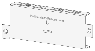
2114A01Q |
Power module filler panel
|
1, provided |
All models |
|
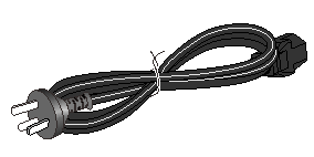
04041104 |
AC power cord
The appearance and parameters for AC power cords vary depending on countries and regions. The AC power cord in this table is a standard AC power cord in China. |
1, provided |
All models |
|
04042967 |
DB9-to-RJ45 console cable
|
1, optional |
All models |
|
0404A1EE |
USB-to-RJ45 console cable
|
1, optional |
All models |
|
14990101 |
SFP port dust cap
|
Same as the number of SFP+ ports |
All models |
|
1499A01G |
QSFP port dust cap
|
Same as the number of QSFP28 ports |
All models |


2 Installing the switch
|
|
CAUTION: Keep the tamper-proof seal on a mounting screw on the chassis cover intact, and if you want to open the chassis, contact H3C for permission. Otherwise, H3C shall not be liable for any consequence caused thereby. |
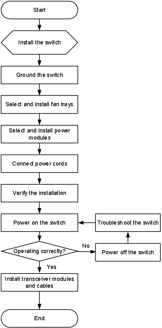
Figure2-1 Hardware installation flow
Installation methods and accessories
Rack-mounting procedures at a glance
You can install the switch in a rack by using only the two front mounting brackets. Additionally, you can use rear mounting brackets, long slide rails, super-short slide rails, or extension rail kits to help support the weight of the switch. For the position of mounting brackets and the distance between the front and rear rack posts, see Table2-1.
Figure2-2 Rack-mounting procedure by using front mounting brackets

Figure2-3 Rack-mounting procedure by using rear mounting brackets or slide rails together with front mounting brackets

|
|
NOTE: If a rack shelf is available, you can put the switch on the rack shelf and slide the switch to a position so that the mounting brackets make close contact with the front rack posts. Then use screws to secure the mounting brackets to the rack. |
Table2-2 Distance requirements between the front and rear rack posts
|
Installation method |
Chassis dimensions |
Distance between the front and rear rack posts |
Rack requirements |
|
Front mounting brackets |
· Height—44 mm (1.73 in)/1 RU · Width—440 mm (17.32 in) · Depth—376.2 mm (14.81 in) ¡ 360 mm (14.17 in) for the chassis ¡ 16.2 mm (0.64 in) for the fan tray handle |
N/A |
· A minimum of 130 mm (5.12 in) between the front rack post and the front door · A minimum of 410 mm (16.14 in) between the front rack post and the rear door |
|
Front and rear mounting brackets, with the rear mounting brackets reaching out of the chassis |
· ≥ 377 mm (14.84 in) · 174 to 338 mm (6.85 to 13.31 in) |
· A minimum of 130 mm (5.12 in) between the front rack post and the front door · A minimum of 153 mm (6.02 in) between the rear rack post and the rear door |
|
|
Front and rear mounting brackets, with the rear mounting brackets not reaching out of the chassis |
332 to 496 mm (13.07 to 19.53 in) |
· A minimum of 130 mm (5.12 in) between the front rack post and the front door · A minimum of 410 mm (16.14 in) between the front rack post and the rear door |
|
|
Front mounting brackets and super-short slide rails (chassis rails not reaching out of the chassis) |
357 to 465 mm (14.06 to 18.31 in) |
||
|
Front mounting brackets and super-short slide rails (chassis rails reaching out of the chassis) |
464 to 572 mm (18.27 to 22.52 in) |
||
|
Front mounting brackets and long slide rails |
562 to 753 mm (22.13 to 29.65 in) |
||
|
Front mounting brackets and extension rail kit |
650 to 850 mm (25.59 to 33.46 in) |
||
|
Front mounting brackets |
N/A |
Installation accessories
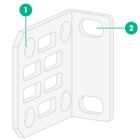
Figure2-4 Front mounting bracket
|
(1) Screw hole for attaching the bracket to the switch |
|
(2) Screw hole for attaching the bracket to the front rack post |
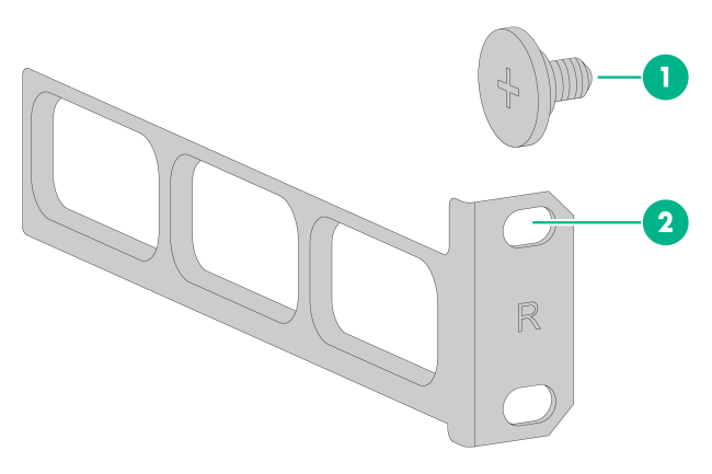
Figure2-5 Rear mounting bracket and shoulder screw
|
(1) Shoulder screw |
(2) Screw hole for attaching the bracket to the rear rack post |
Figure2-6 1U long slide rail and chassis rail
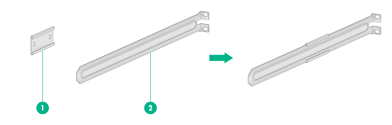
|
(1) Chassis rail |
(2) Long slide rail |
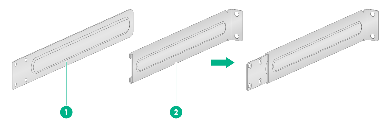
Figure2-7 1U super-short slide rail and chassis rail
|
(1) Chassis rail |
(2) Super-short slide rail |
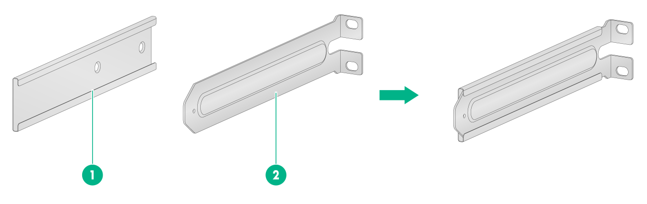
Figure2-8 1U extension rail kit
|
(1) Extension bracket |
(2) Extension rail |
Installing the switch in a 19-in rack
|
|
IMPORTANT: · M4 screws are used for attaching the mounting brackets and chassis rails to the chassis. As a best practice, use a torque of 12 kgf-cm (1.18 Nm) to fasten M4 screws. · M6 screws and cage nuts are user supplied. As a best practice, use a torque of 30 kgf-cm (2.94 Nm) to fasten M6 screws. · Shoulder screws are used to support the weight of the switch together with rear mounting brackets. As a best practice, use a torque of 12 kgf-cm (1.18 Nm) to fasten shoulder screws. |
Rack-mounting by using front mounting brackets
Attaching the front mounting brackets to the chassis
The switch has one mounting position near the network ports and one mounting position near the power modules for mounting brackets. You can select one position as needed.
To attach the front mounting brackets to the chassis:
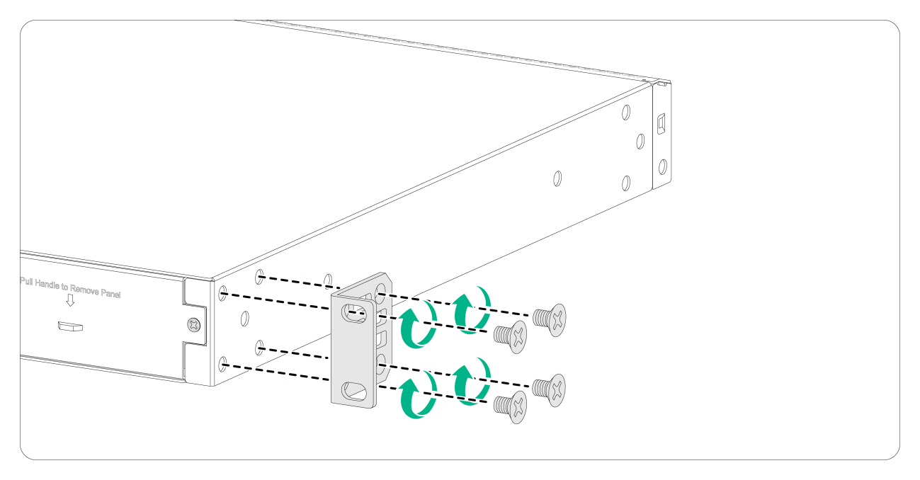
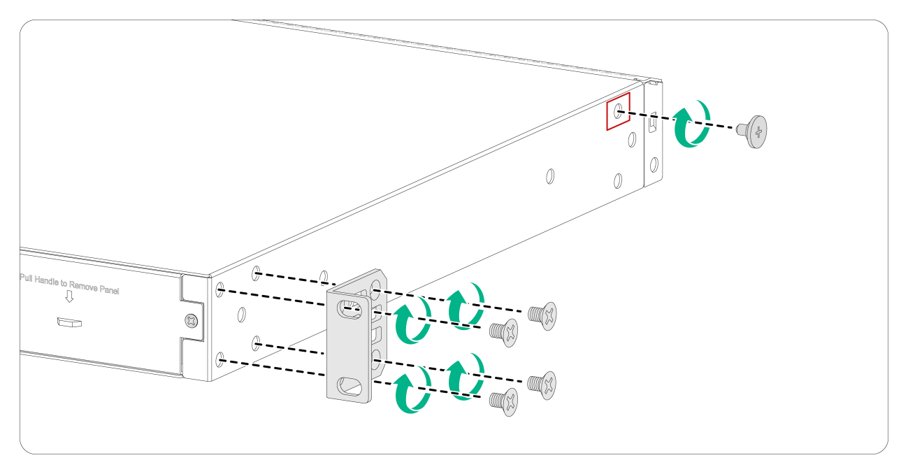
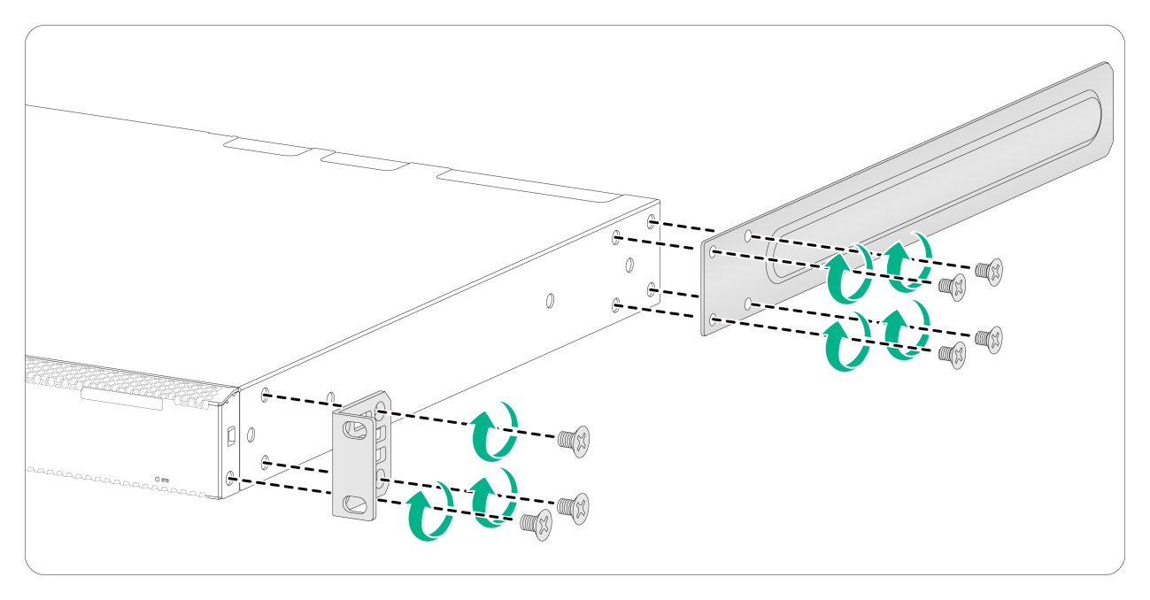
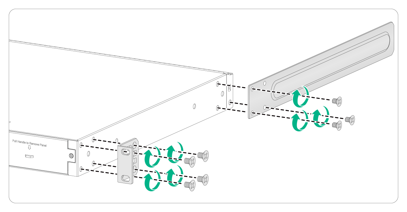
1. Place the wide flange of the mounting bracket against the chassis side panel. Align the mounting bracket installation holes with the screw holes in the chassis.
¡ To install the mounting brackets at the port-side mounting position, see Figure2-9.
¡ To install the mounting brackets at the power module-side mounting position, see Figure2-10.
2. Fasten the M4 screws to secure the mounting bracket to the switch.
3. Attach the front mounting bracket to the other side of the chassis in the same way.
Figure2-9 Attaching the front mounting brackets to the switch (port-side mounting position)
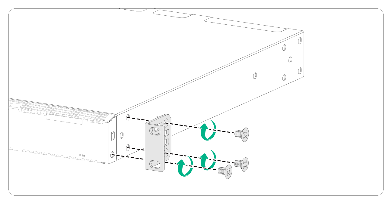
Figure2-10 Attaching the front mounting brackets to the switch (power module-side mounting position)
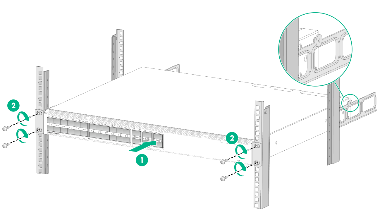
Mounting the switch in the rack
This task requires two people.
To mount the switch in the rack:
1. Wear an ESD wrist strap and make sure it makes good skin contact and is reliably grounded.
2. Verify that the front mounting brackets have been securely attached to the switch chassis. See "Attaching the front mounting brackets to the chassis."
3. Attach cage nuts to the front rack posts.
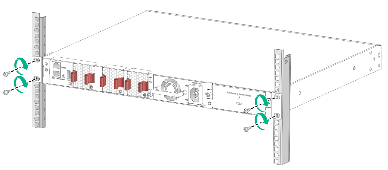
4. One person supports the bottom of the switch, and moves the switch to an appropriate position based on the installation positions of the front mounting brackets.
5. Another person uses M6 screws and cage nuts to attach the mounting brackets to the rack and verifies that they are at the same level.
Figure2-11 Mounting the switch in the rack (port-side mounting position for the mounting brackets)
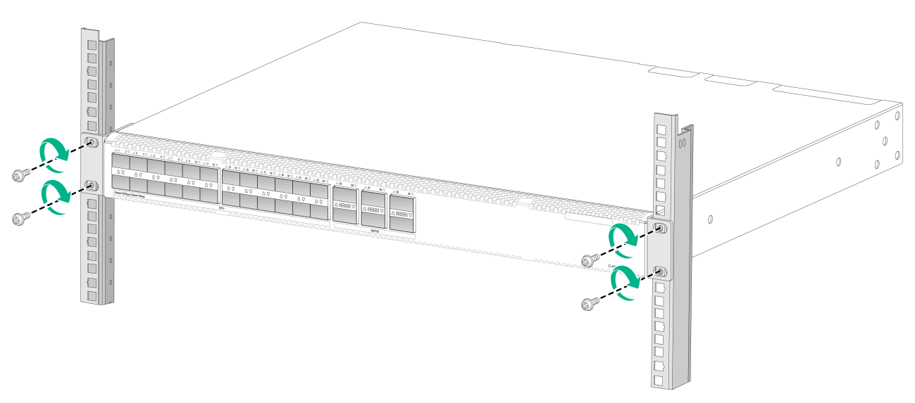
Figure2-12 Mounting the switch in the rack (power module-side mounting position for the mounting brackets)
Rack-mounting by using front and rear mounting brackets
You can install the front mounting brackets at the port-side or power module-side mounting position as needed.
Attaching the front mounting brackets and shoulder screws to the switch
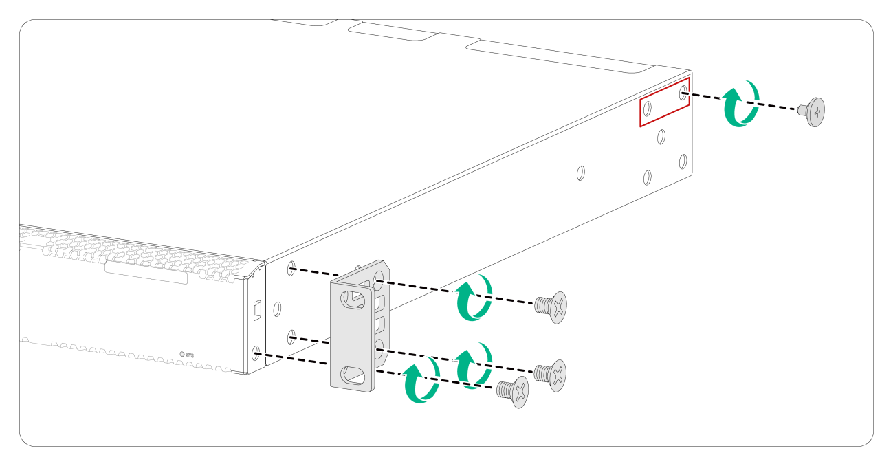
1. Place the wide flange of the front mounting bracket against the chassis side panel. Align the mounting bracket installation holes with the screw holes in the chassis. See Figure2-13.
2. Fasten the M4 screws to attach the mounting bracket to the chassis.
3. Unpack the shoulder screws, and attach a shoulder screw to an installation position.
For port-side mounting position for the mounting brackets, the switch provides two installation positions as red-marked in Figure2-13. For power module-side mounting position for the mounting brackets, the switch provides one installation position as red-marked in Figure2-14.
4. Attach the front mounting bracket and shoulder screw to the other side of the chassis in the same way.
Figure2-13 Attaching the front mounting brackets and shoulder screws to the chassis (port-side mounting position for the mounting brackets)
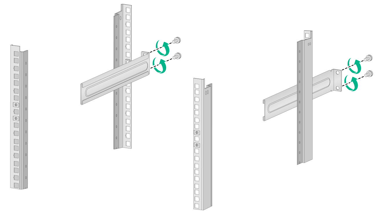
Attaching the rear mounting brackets to the rack
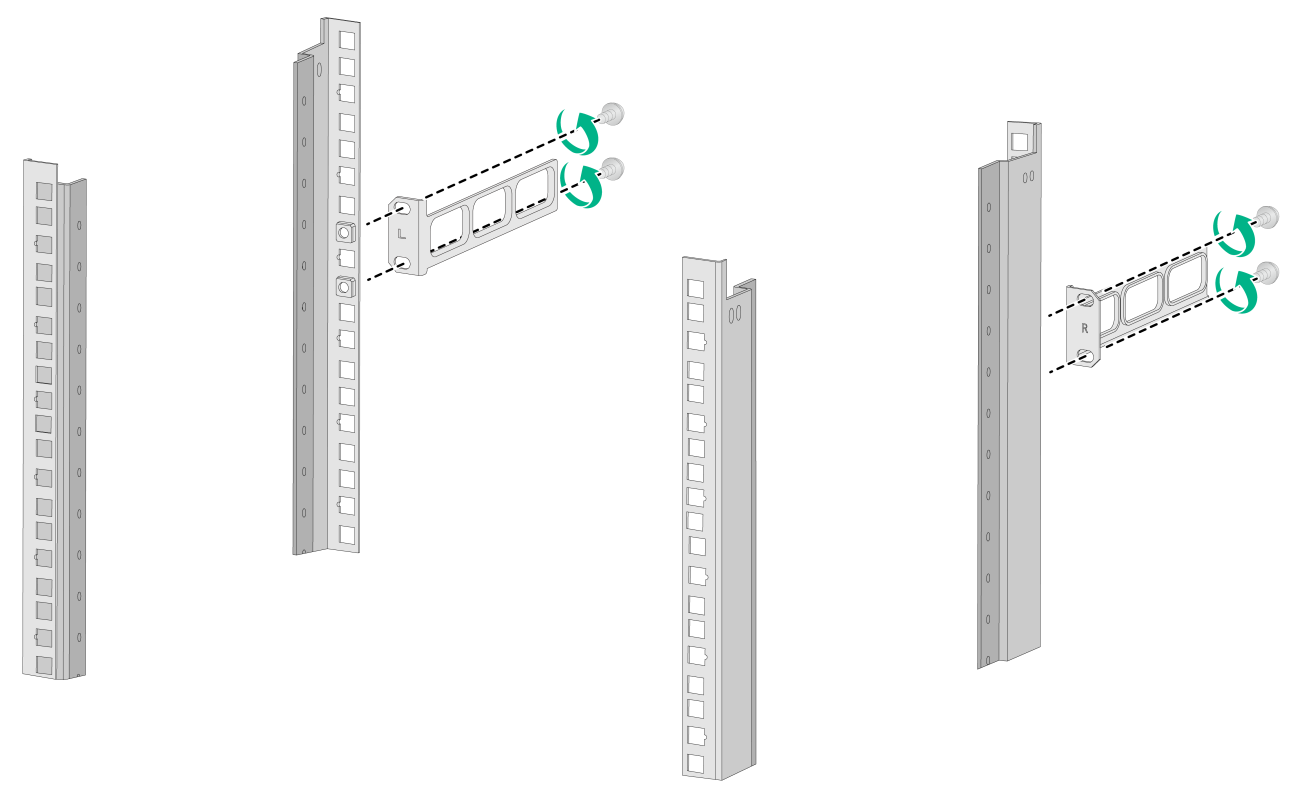
1. Orient the rear mounting brackets with the wide flange inside or outside the rack as required, as shown in Figure2-15 and Figure2-16.
2. Use M6 screws and cage nuts to attach the rear mounting brackets to the rear rack posts. Make sure the cage nuts on the left and right rear rack posts are at the same height.
Do not fully tighten the M6 screws before mounting the switch in the rack.
Figure2-15 Attaching the rear mounting brackets to the rack with the wide flange inside the rack
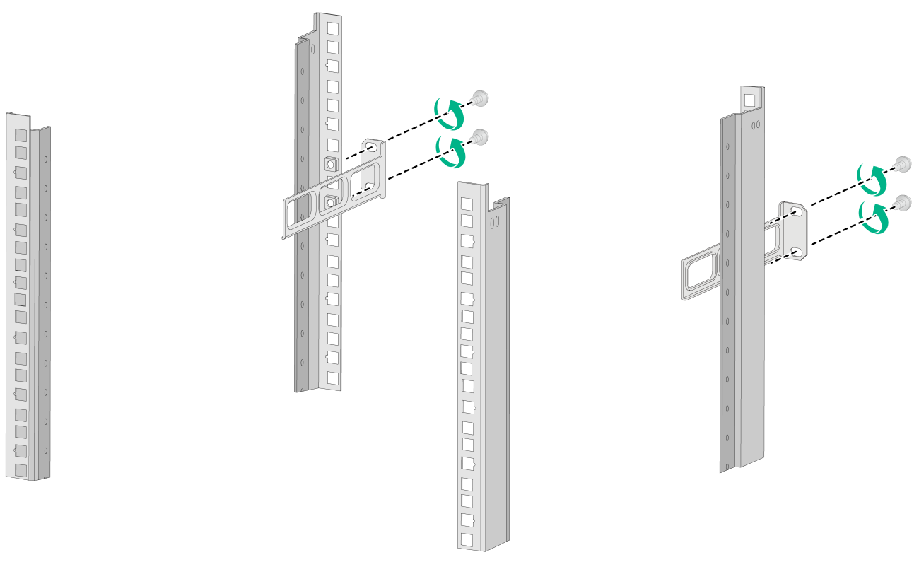
Figure2-16 Attaching the rear mounting brackets to the rack with the wide flange outside the rack
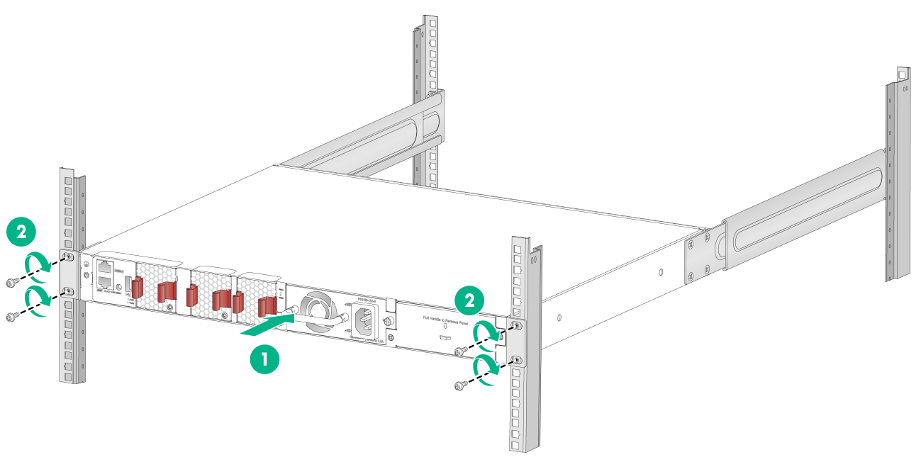
Mounting the switch in the rack
1. Wear an ESD wrist strap and make sure it makes good skin contact and is reliably grounded.
2. Verify that the front mounting brackets and shoulder screws have been securely attached to the switch chassis. See "Attaching the front mounting brackets and shoulder screws to the switch."
3. Attach cage nuts to the front rack posts. Make sure the cage nuts on the left and right rear rack posts are at the same height.
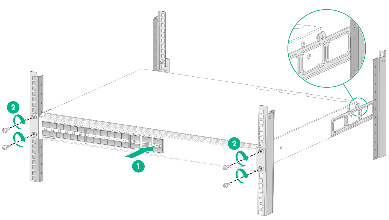
4. One person supports the chassis bottom with one hand, holds the front part of the chassis with the other hand, and pushes the chassis into the rack gently.
Make sure the shoulder screws are in close contact with the upper edges of the rear mounting brackets, as shown in Figure2-17 and Figure2-18.
5. The other person attaches the front mounting brackets with M6 screws and cage nuts to the front rack posts.
Make sure the front and rear mounting brackets have securely attached the switch to the rack.
Figure2-17 Mounting the switch in the rack (with the wide flange of the mounting brackets inside the rack)
Rack-mounting by using front mounting brackets and long or super-short slide rails
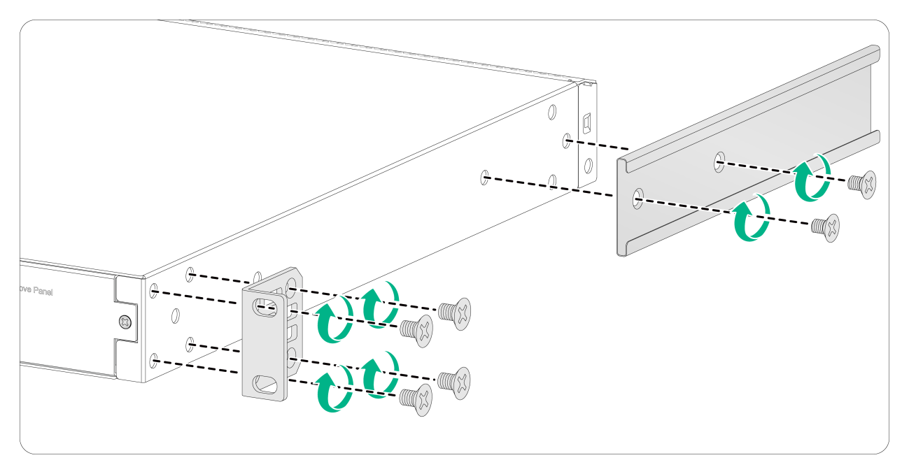
Attaching the chassis rails to the chassis
1. Place the wide flange of the mounting bracket against the chassis side panel. Align the mounting bracket installation holes with the appropriate screw holes in the chassis. Use the provided M4 screws to attach the mounting bracket to the chassis.
2. Place the chassis rail against the chassis side panel. Align the chassis rail installation holes with the screw holes. Use the provided M4 screws to attach the chassis rail to the chassis. See Figure2-19 to Figure2-24.
You can use super-short slide rails and long chassis rails to rack-mount the switch. Based on the rack depth, install the long chassis rails with the chassis rails not reaching out of the chassis, as shown in Figure2-20 through Figure2-23 or with the chassis rails reaching out of the chassis, as shown in Figure2-21 through Figure2-24.
Figure2-19 Attaching the mounting brackets and chassis rails to the switch (port-side mounting position for the mounting brackets, long slide rails)
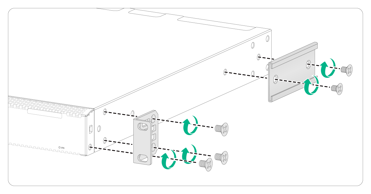
Figure2-20 Attaching the mounting brackets and chassis rails to the switch (port-side mounting position for the mounting brackets, super-short slide rails, chassis rails not reaching out of the chassis)
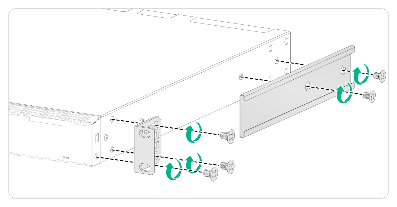
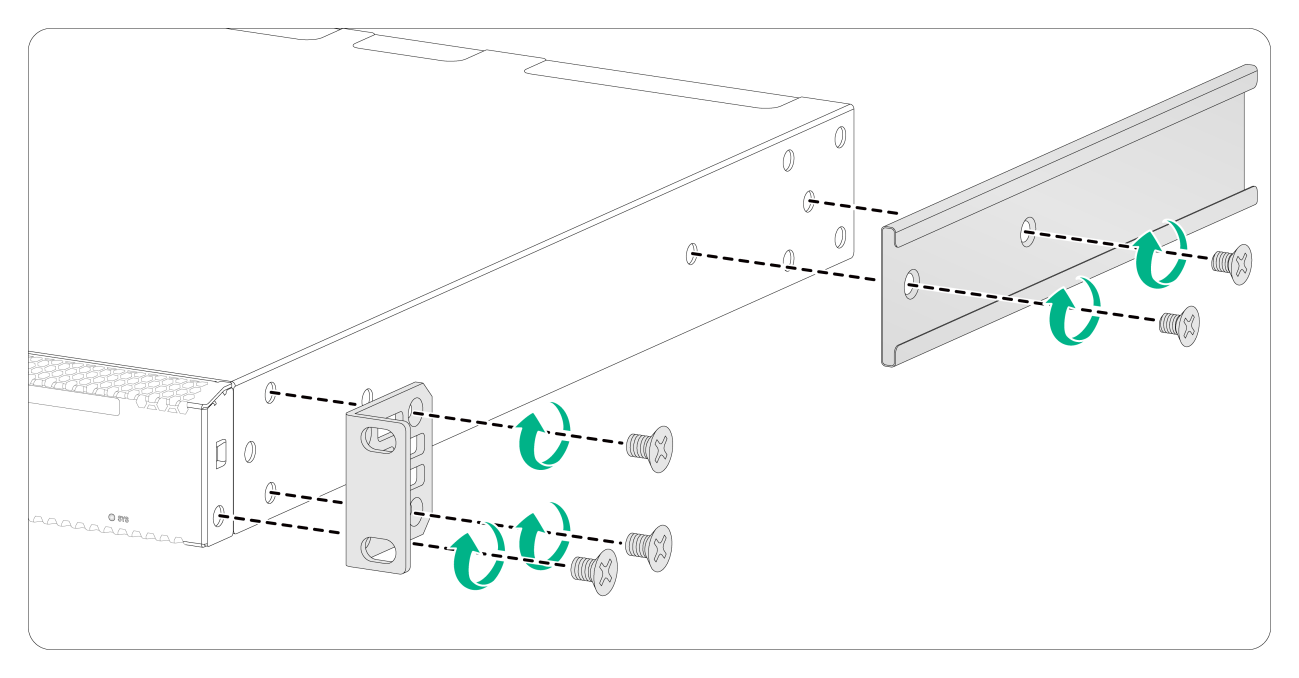
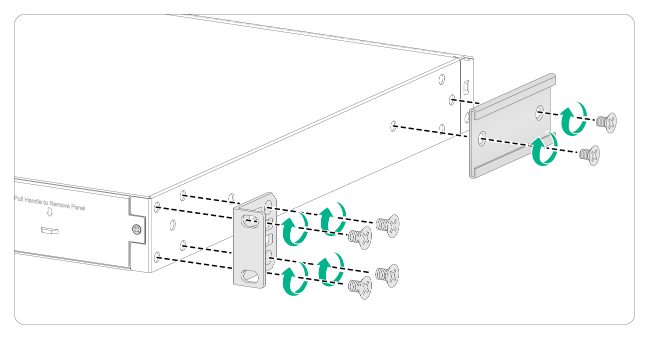
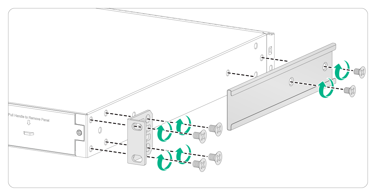
Figure2-24 Attaching the mounting brackets and chassis rails to the switch (power module-side mounting position for the mounting brackets, super-short slide rails, chassis rails reaching out of the chassis)
|
|
NOTE: Secure the mounting brackets and chassis rails to both sides of the chassis in the same way. |
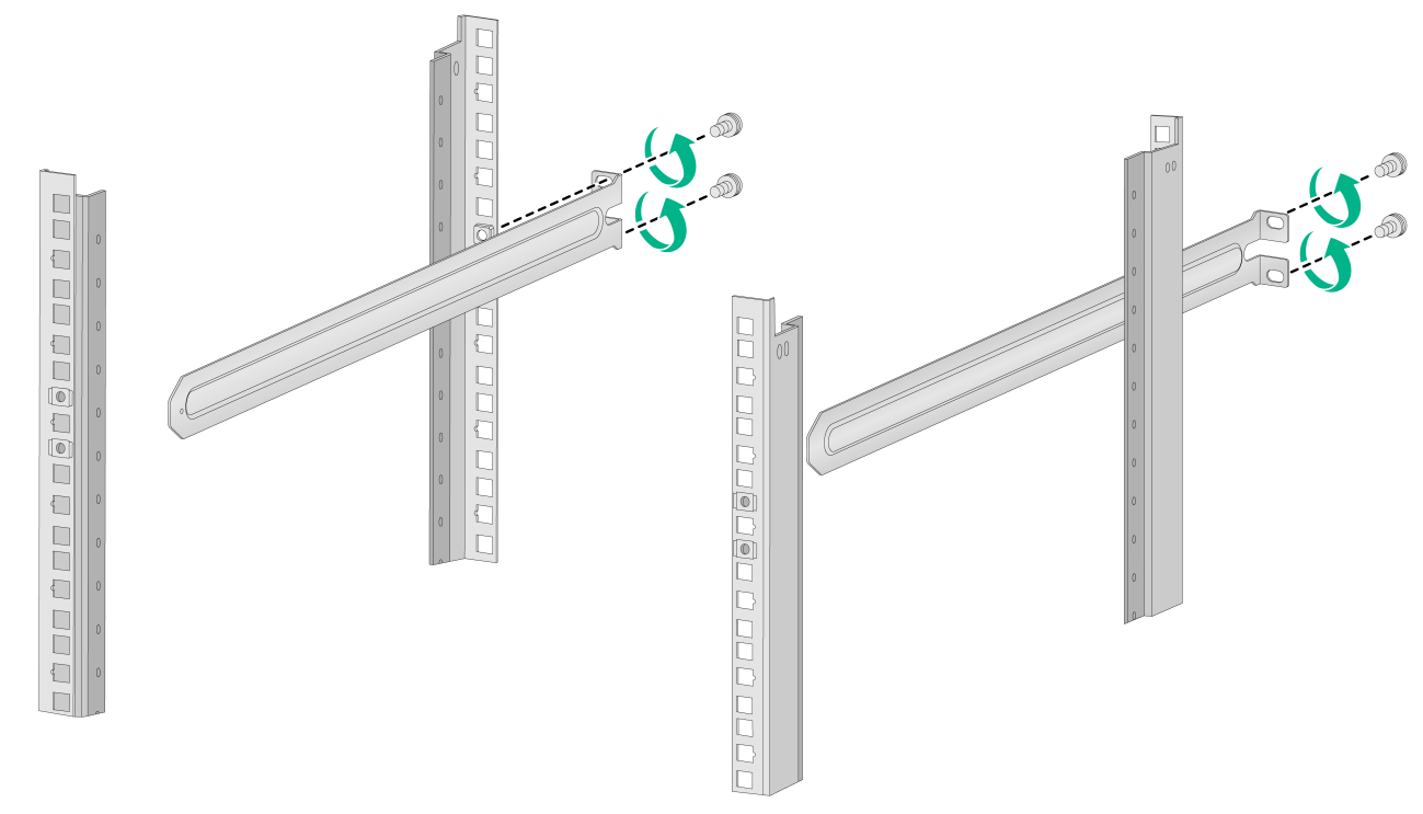
Attaching the long or super-short slide rails to the rack
The procedure is the same for attaching long and super-short slide rails to the rack. This section uses the long slide rails as an example.
To attach the slide rails to the rack:
1. Identify the slide rail installation position in the rack.
2. Install cage nuts in the mounting holes in the rack posts.
3. Align the screw holes in one slide rail with the cage nuts in a rear rack post. Use M6 screws to attach the slide rail to the post. See Figure2-25.
4. Repeat the preceding steps to attach the other slide rail to the other rear rack post.
Keep the two slide rails at the same height so the slide rails can attach into the chassis rails.
Figure2-25 Installing the long slide rails
Mounting the switch in the rack
This task requires two people.
To mount the switch in the rack:
1. Wear an ESD wrist strap and make sure it makes good skin contact and is reliably grounded.
2. Verify that the mounting brackets and chassis rails have been securely attached to the switch chassis. See "Attaching the chassis rails to the chassis."
3. Verify that the slide rails have been correctly attached to the rear rack posts. See "Attaching the long or super-short slide rails to the rack."
4. Attach cage nuts to the front rack posts and make sure they are at the same level as the slide rails.
5. One person performs the following operations:
a. Supporting the bottom of the switch, aligns the chassis rails with the slide rails on the rack posts.
b. Pushes the switch slowly to slide the chassis rails along the slide rails until the mounting brackets are flush with the rack posts.
|
|
IMPORTANT: If you use long slide rails to rack-mount the switch, make sure the front ends of the long slide rails reach out of the chassis rails for a maximum of 20 mm (0.79 in). If you use super-short slide rails to rack-mount the switch, make sure the front ends of the super-short slide rails reach inside the chassis rails for a minimum of 110 mm (4.33 in) after installation. |
6. Another person uses user-supplied M6 screws to attach the mounting brackets to the rack.
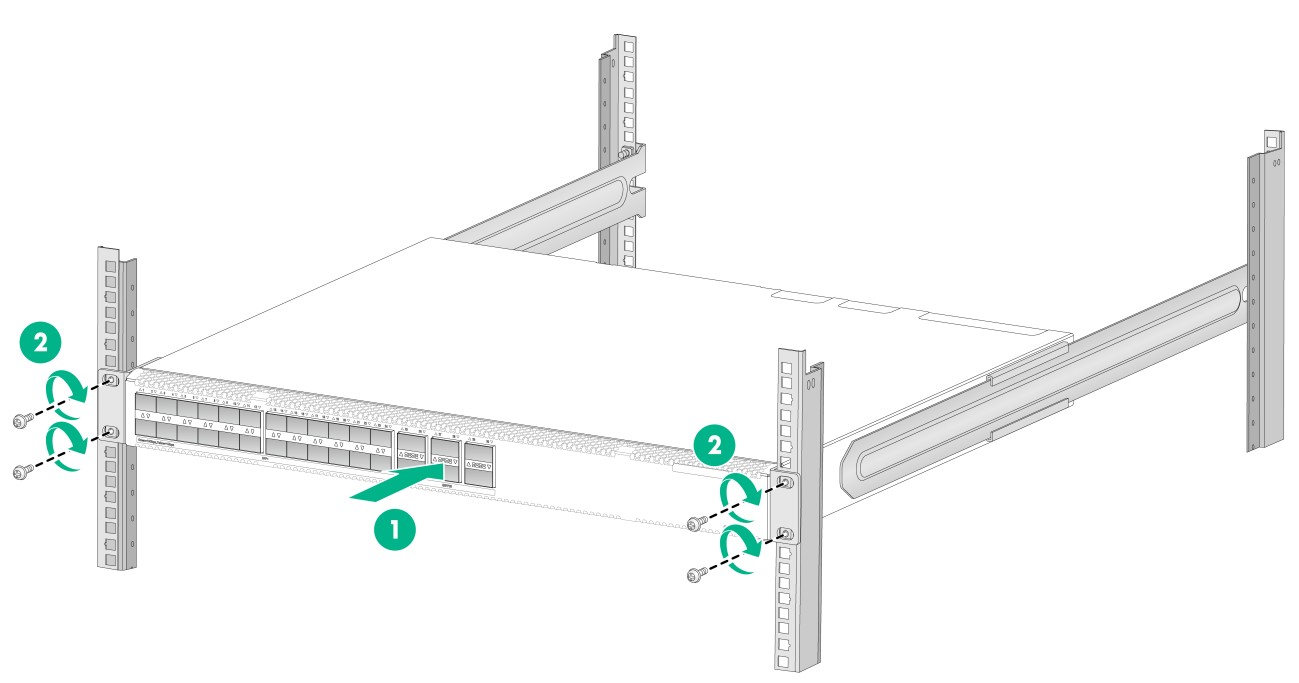
Figure2-27 Mounting the switch in the rack (port-side mounting position for the mounting brackets, super-short slide rails, chassis rails not reaching out of the chassis)
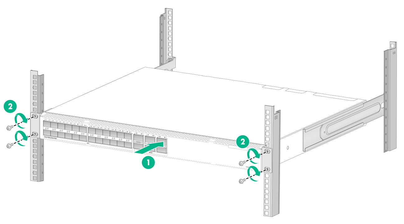
Figure2-28 Mounting the switch in the rack (port-side mounting position for the mounting brackets, super-short slide rails, chassis rails reaching out of the chassis)
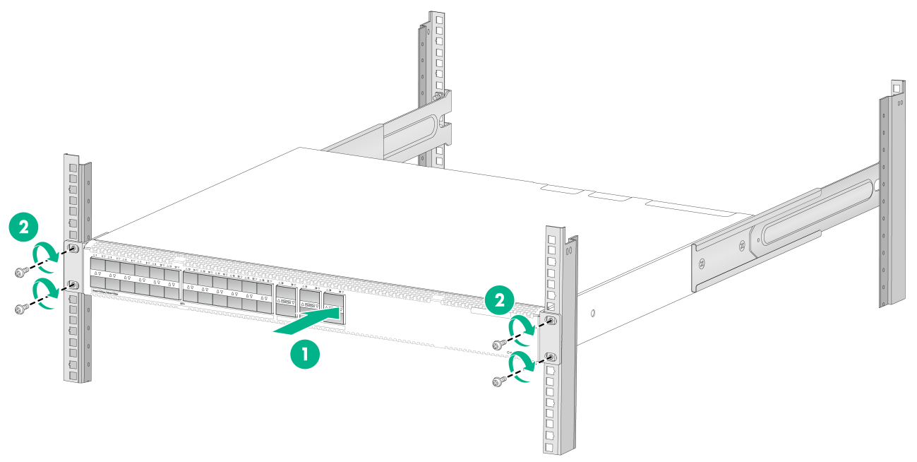
Figure2-29 Mounting the switch in the rack (power module-side mounting position for the mounting brackets, long slide rails)
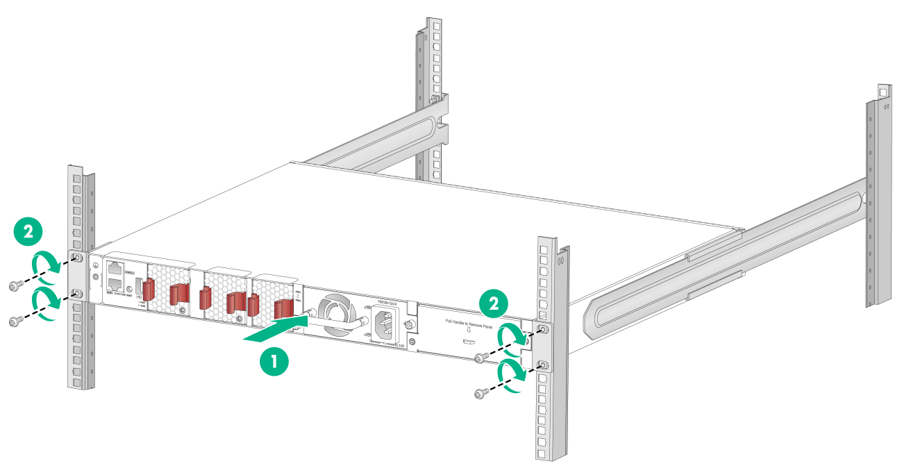
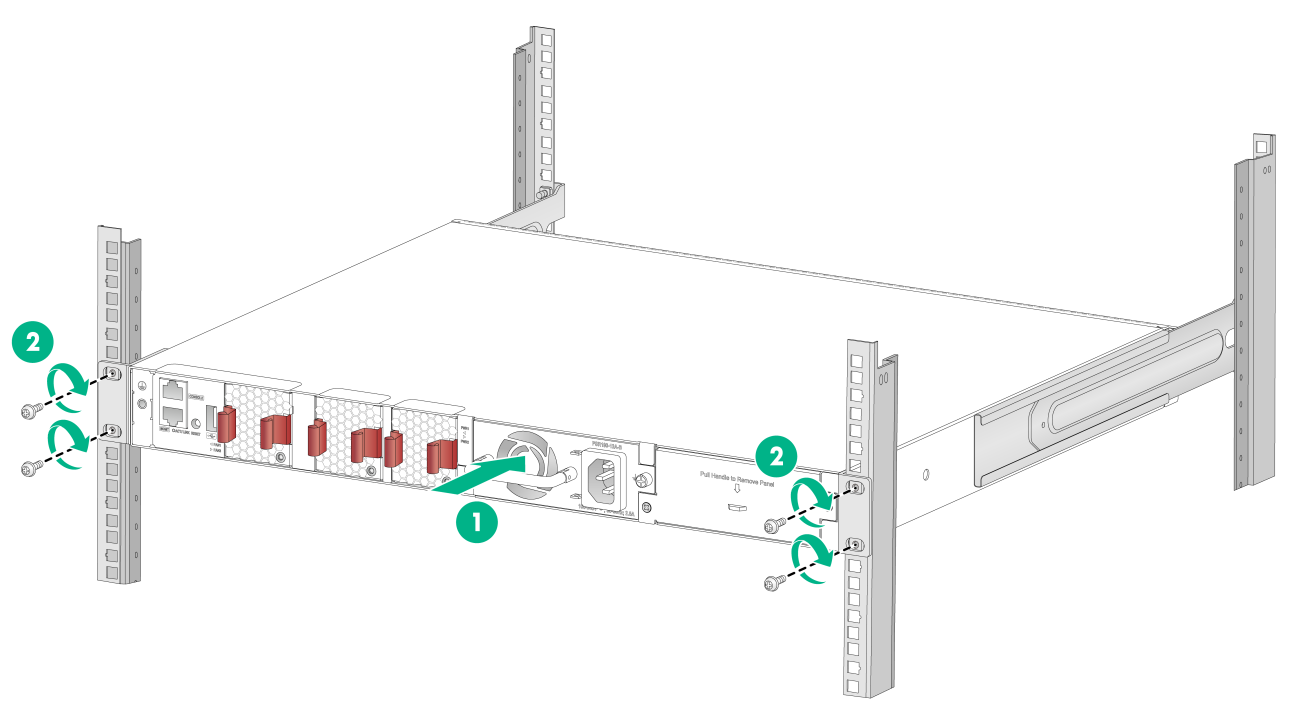
Figure2-31 Mounting the switch in the rack (power module-side mounting position for the mounting brackets, super-short slide rails, chassis rails reaching out of the chassis)
Rack-mounting by using front mounting brackets and extension brackets and rails
Attaching the extension bracket to the chassis
1. Place the wide flange of the mounting bracket against the chassis side panel. Align the mounting bracket installation holes with the appropriate screw holes in the chassis. Use the provided M4 screws to attach the mounting bracket to the chassis.
2. Place the extension bracket against the chassis side panel. Align the extension bracket installation holes with the screw holes. Use the provided M4 screws to attach the chassis rail to the chassis. See Figure2-32 and Figure2-33.
|
|
NOTE: Secure the front mounting brackets and extension brackets to both sides of the chassis in the same way. |
Attaching the extension rails to the rack
1. Identify the extension rail installation position in the rack.
2. Install cage nuts in the mounting holes in the rack posts.
3. Align the screw holes in one extension rail with the cage nuts in a rear rack post. Use M6 screws to attach the extension rail to the post. See Figure2-25.
4. Repeat the preceding steps to attach the other extension rail to the other rear rack post.
Keep the two extension rails at the same height so the extension rails can attach into the extension brackets.
Figure2-34 Installing the extension rails
Mounting the switch in the rack
This task requires two people.
To mount the switch in the rack:
1. Wear an ESD wrist strap and make sure it makes good skin contact and is reliably grounded.
2. Verify that the mounting brackets and extension brackets have been securely attached to the switch chassis. See "Attaching the extension bracket to the chassis."
3. Verify that the extension rails have been correctly attached to the rear rack posts. See "Attaching the extension rails to the rack."
4. Attach cage nuts to the front rack posts and make sure they are at the same level as the extension rails.
5. One person performs the following operations:
a. Supporting the bottom of the switch, aligns the extension brackets with the extension rails on the rack posts.
b. Pushes the switch slowly to slide the extension rails along the extension brackets until the mounting brackets are flush with the rack posts.
6. Another person uses M6 screws to attach the mounting brackets to the rack.
Figure2-35 Mounting the switch in the rack (port-side mounting position for the mounting brackets)
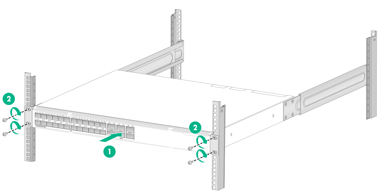
Figure2-36 Mounting the switch in the rack (power module-side mounting position for the mounting brackets)
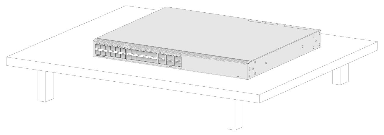
Mounting the switch on a workbench
|
|
IMPORTANT: · Ensure good ventilation and 10 cm (3.9 in) of clearance around the chassis for heat dissipation. · Avoid placing heavy objects on the switch. |
To mount the switch on a workbench:
1. Verify that the workbench is sturdy and reliably grounded.
2. Place the switch with bottom up, and clean the round holes in the chassis bottom with dry cloth.
3. Attach the rubber feet to the four round holes in the chassis bottom.
4. Place the switch with upside up on the workbench.
Figure2-37 Mounting the device on a workbench (1)
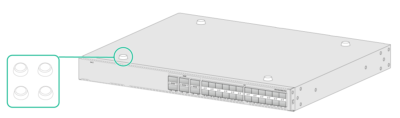
Figure2-38 Mounting the device on a workbench (2)
Grounding the switch
|
|
WARNING! · Correctly connecting the switch grounding cable is crucial to lightning protection, ESD, and EMI protection. For information about lightning protection, see H3C Network Devices Lightning Protection Guide. · Connect the grounding cable to the grounding system in the equipment room. Do not connect it to a fire main or lightning rod. |
|
|
CAUTION: To guarantee the grounding effect and avoid switch damage, use the grounding cable provided with the switch to connect to the grounding strip in the equipment room. |
To protect against the following types of issues, use a grounding cable to connect the switch to the earthing facility at the installation site:
· Bodily injury from electric shocks.
· Device and power and data line damages.
· Electrical fires, lightning strokes, electromagnetic coupling interferences, and ESD damages.
You can ground the switch in one of the following ways, depending on the grounding conditions available at the installation site:
· Connecting the grounding cable to the chassis
· Connecting the grounding cable to a grounding strip
|
|
NOTE: The power and grounding terminals in this section are for illustration only. |
If a grounding strip is available at the installation site, connect the grounding cable to the grounding strip.
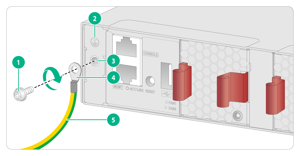
Connecting the grounding cable to the chassis
1. Remove the grounding screw from the rear panel of the switch chassis.
2. Use the grounding screw to attach the ring terminal of the grounding cable to the grounding screw hole. Fasten the screw. The recommended torque is 5 kgf-cm (0.49 Nm).
|
|
IMPORTANT: Orient the grounding cable as shown in Figure2-39 so you can easily install or remove the fan tray. |
Figure2-39 Connecting the grounding cable to the chassis
|
(1) Grounding screw |
(2) Grounding sign |
|
(3) Grounding hole |
(4) Ring terminal |
|
(5) Grounding cable |
|
3. Verify that the grounding cable has been securely connected to the rear grounding point.
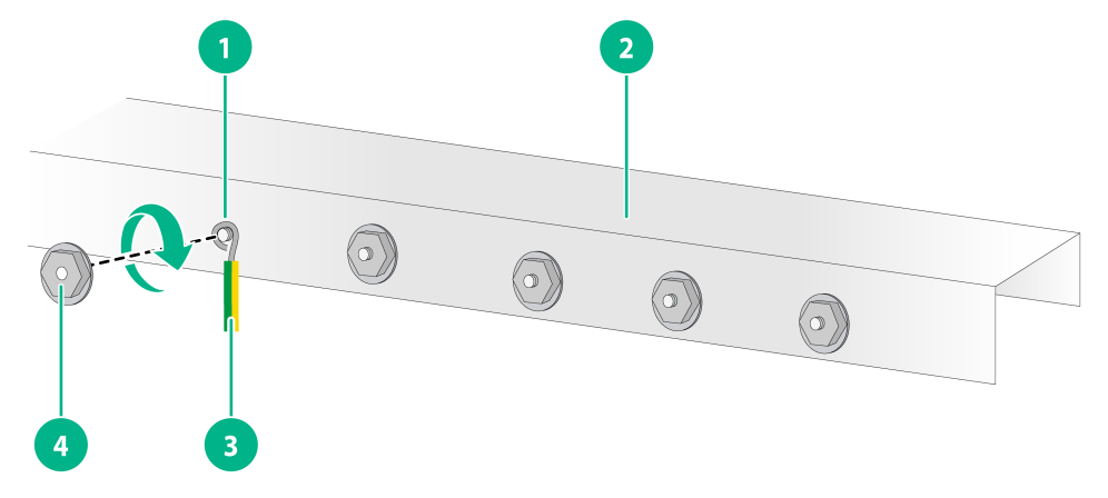
Connecting the grounding cable to a grounding strip
1. Use needle-nose pliers to bend the bare metal part to the shape as shown in Figure2-40. Make sure the bended part can securely attached to the grounding post on the grounding strip.
2. Peel 20 mm (0.79 in) of insulation sheath by using a wire stripper.
3. Attach the bended part of the grounding cable to the grounding post and use the hex nut to fasten the bended part to the post.
Figure2-40 Connecting the grounding cable to the grounding strip
|
(1) Grounding post |
(2) Grounding strip |
|
(3) Grounding cable |
(4) Hex nut |
Verifying the connection after grounding the switch
· If you ground the switch by using a grounding strip:
a. Use a multimeter to measure the resistance between the switch grounding terminal and grounding point, and make sure the resistance is less than 0.1W.
b. Use a grounding resistance tester to measure the grounding resistance of the grounding strip, and make sure the grounding resistance is less than 1W.
· If you ground the switch by using a grounding conductor buried in the earth ground:
a. Use a multimeter to measure the resistance between the switch grounding terminal and grounding point, and make sure the resistance is less than 0.1W.
b. Use a grounding resistance tester to measure the grounding resistance of the angle iron in the ground, and make sure the grounding resistance is less than 10W. For locations with high soil resistivity, sprinkle some resistance reducer to reduce soil resistivity or replace soil around the grounding strip with soil with lower resistance.
For information about resistance measurement, see H3C Network Devices Lightning Protection Guide.
Installing and removing a fan tray
|
|
CAUTION: · Install three fan trays of the same model on the switch. Do not power on the switch when it does not have all fan trays installed. Make sure the air flow direction of the fan trays is the same as that of the fans on the power modules. · Make sure slots are installed with fan trays or blank filler panels for the device to operate. · Do not remove multiple fan trays simultaneously. You can remove another fan tray only after you finish replacing one fan tray. Make sure you finish replacing a fan tray within 3 minutes. |
The switch comes with empty fan tray slots. Choose the fan tray models based on the ventilation requirement of the site. The air flow direction varies by fan tray model.
· The LSPM1FANSA-SN provides power-to-port air flow.
· The LSPM1FANSB-SN provides port-to-power air flow.
For more information about the fan trays, see removable fan trays in Hardware Information and Specifications.
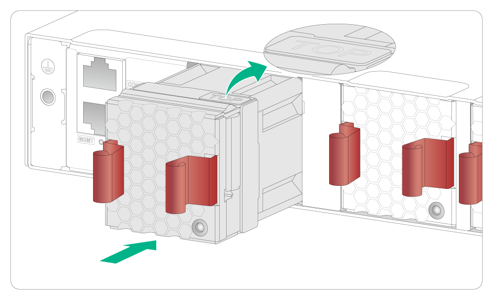
Installing a fan tray
|
|
CAUTION: To prevent damage to the fan tray or the connectors on the backplane, insert the fan tray gently. If you encounter a hard resistance while inserting the fan tray, pull out the fan tray and insert it again. |
To install a fan tray:
1. Wear an ESD wrist strap and make sure it makes good skin contact and is reliably grounded.
2. Unpack the fan tray and verify that the fan tray model is correct.
3. Grasp the two handles of the fan tray with the side marked TOP facing up, and slide the fan tray along the guide rails into the slot until the fan tray seats in the slot and has a firm contact with the backplane.
Figure2-41 Installing a fan tray
Removing a fan tray
|
|
WARNING! · Do not touch conductors or terminals on the fan trays. · Do not place the fan tray in a moist place. Prevent liquid from entering the fan tray. · Fan trays with faulty internal wiring and conductors require maintenance from maintenance engineers. Do not disassemble the faulty fan trays. |
To remove a fan tray:
1. Wear an ESD wrist strap and make sure it makes good skin contact and is reliably grounded.
2. Grasp the two handles of the fan tray, as shown by callout 1 in Figure2-42, and pull out the fan tray slowly along the guide rails.
3. Put the removed fan tray in an antistatic bag.
Figure2-42 Removing a fan tray
Installing and removing a power module
|
|
WARNING! In power redundancy mode, you can replace a power module without powering off the switch but you must strictly follow the installation and removal procedures in Figure2-43 and Figure2-44 to avoid any bodily injury or damage to the switch. |
|
|
CAUTION: Provide a circuit breaker for each power module. |
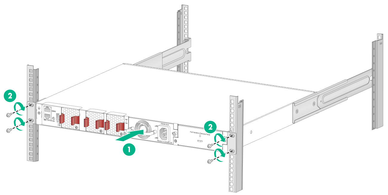
Figure2-43 Installation procedure
![]()
![]()
The PSR180-12A-F and PSR180-12A-B power modules are available for the switch. The installation and removal procedures are the same for the PSR180-12A-F and PSR180-12A-B power modules. The following procedures install and remove a PSR180-12A-B power module.
Installing a power module
|
|
CAUTION: To prevent damage to the power module or the connectors on the backplane, insert the power module gently. If you encounter a hard resistance when inserting the power module, pull out the power module and insert it again. |
To install a power module:
1. Wear an ESD wrist strap and make sure it makes good skin contact and is reliably grounded.
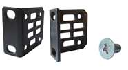
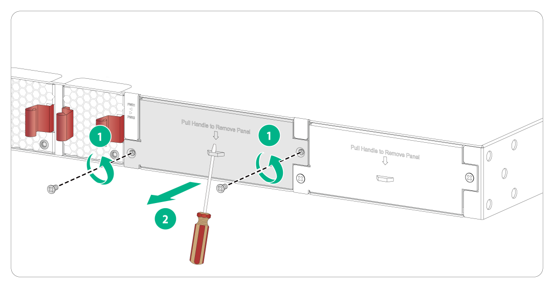
2. Remove the filler panel from the target power module slot as follows:
a. Remove the screws on the filler panel.
b. Use a flathead screwdriver to remove the filler panel.
Figure2-45 Removing the filler panel
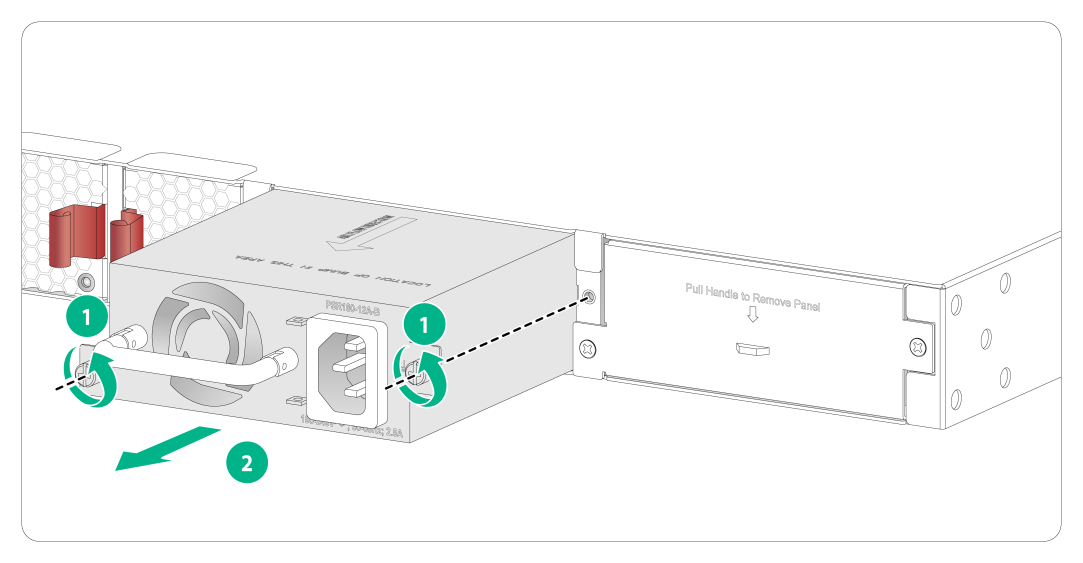
3. Unpack the power module and verify that the power module model is correct.
4. Correctly orient the power module with the power module slot (use the letters on the power module faceplate for orientation), grasp the handle of the power module with one hand and support its bottom with the other, and slide the power module slowly along the guide rails into the slot (see callout 1 in Figure2-46).
5. Fasten the captive screws on the power module with a Phillips screwdriver to secure the power module in the chassis (see callout 2 in Figure2-46). If the captive screw cannot be tightly fastened, verify the installation of the power module.
The recommended torque is 5 kgf-cm (0.49 Nm).
6. Install the filler panel over the empty power module slot to prevent dust and ensure good ventilation if you install only one power module.
Figure2-46 Installing a power module

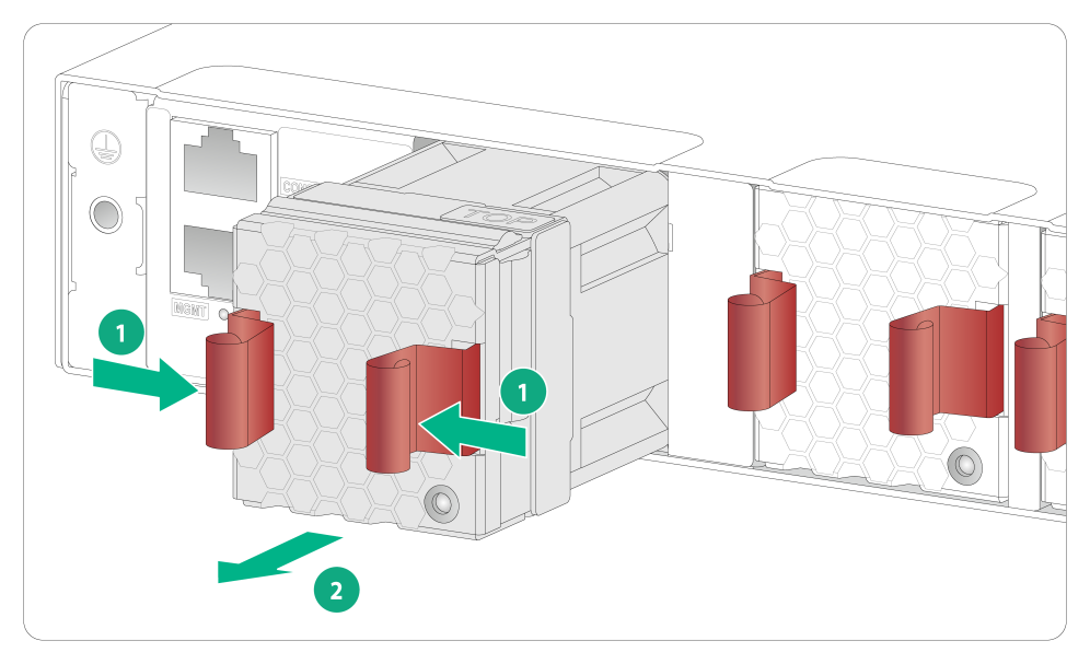
Removing a power module
1. Wear an ESD wrist strap and make sure it makes good skin contact and is reliably grounded.
2. Disconnect the power cord.
3. Loosen the captive screws of the power module with a Phillips screwdriver until they are completely disengaged.
4. Grasp the handle of the power module with one hand and pull it out a little, support the bottom with the other hand, and pull the power module slowly along the guide rails out of the slot.
Put away the removed power module in an antistatic bag or the power module package bag for future use.
Figure2-47 Removing a power module
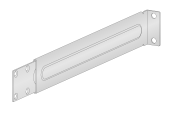
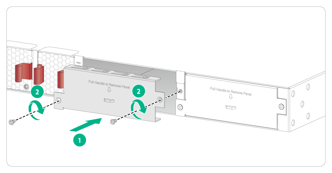
5. Install the filler panel to prevent dust and ensure good ventilation if no power module is installed in the slot.
Figure2-48 Installing a filler panel
Connecting the power cord
|
|
WARNING! Provide a circuit breaker for each power module and make sure the circuit breaker is off before installation. |
To connect the power cord for a power module:
1. Wear an ESD wrist strap and make sure it makes good skin contact and is reliably grounded.
2. Attach the power cord retainer clip (supplied with the power module) into the two holes next to the AC-input power receptacle on the power module, and pull the retainer clip leftwards (see Figure2-49).
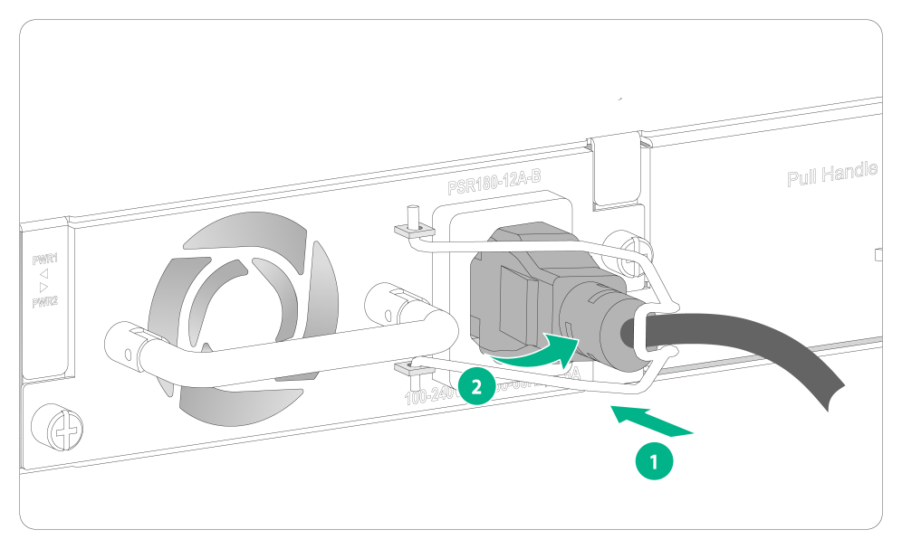
3. Connect one end of the AC power cord supplied with the power module to the power receptacle (see callout 1 in Figure2-50).
4. Pull the retainer clip rightwards to secure the connector to the AC-input power receptacle (see callout 2 in Figure2-50).
5. Connect the other end of the power cord to an AC power source.
Figure2-49 Connecting a power cord (1)
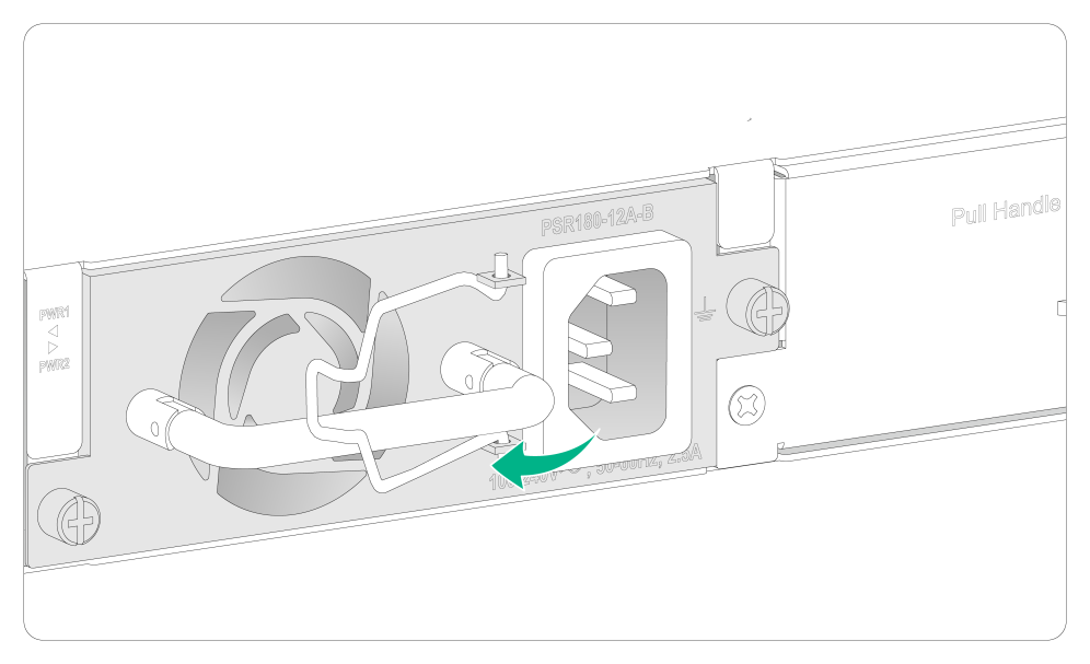
Figure2-50 Connecting a power cord (2)
Verifying the installation
After you complete the installation, verify the following information:
· There is enough space for heat dissipation around the switch, and the rack or workbench is stable.
· The grounding cable is securely connected.
· The correct power source is used.
· The power cords are correctly connected.
· All the interface cables are cabled indoors. If any cable is routed outdoors, verify that the socket strip with lightning protection and lightning arresters for network ports have been correctly connected.
3 Accessing the switch for the first time
Connecting the switch to a configuration terminal
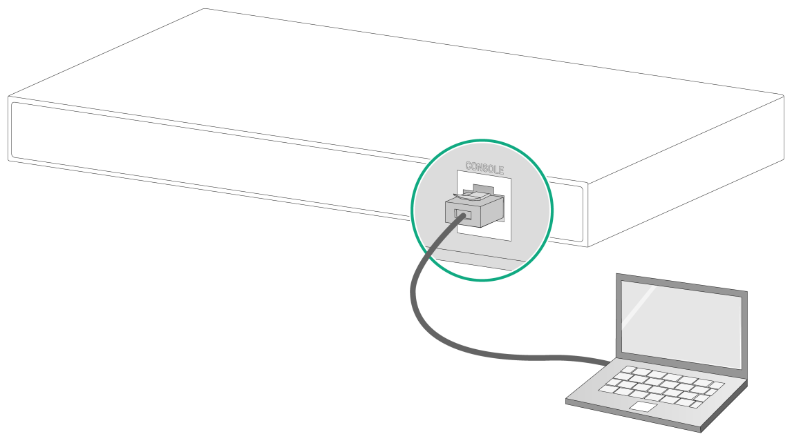
You can connect the switch to a configuration terminal by using the serial console port.
In Figure3-1, the switch is connected to a configuration terminal (PC as an example) from the serial console port.
Figure3-1 Connecting the switch to a configuration terminal
As shown in Table3-1, two types of console cables can be used for connecting the switch to a configuration terminal. No serial console cable is provided with the switch. Purchase a console cable from H3C.
Table3-1 Connection methods and console cables
|
Connection method |
Console cable type |
Configuration terminal-side connector |
Switch-side connector |
|
Using the serial console port for connection |
DB9-to-RJ45 console cable |
DB-9 female connector |
RJ-45 connector |
|
USB-to-RJ45 console cable |
USB connector |
RJ-45 connector |
Connecting a DB9-to-RJ45 console cable
|
|
CAUTION: Follow these guidelines when you connect a DB9-to-RJ45 console cable: · Identify the mark on the serial console port and make sure you are connecting to the correct port. · The serial ports on PCs do not support hot swapping. To connect a PC to an operating switch, first connect the PC end. To disconnect a PC from an operating switch, first disconnect the switch end. |
A DB9-to-RJ45 serial console cable is an 8-core shielded cable, with a crimped RJ-45 connector at one end for connecting to the serial console port of the switch, and a DB-9 female connector at the other end for connecting to the serial port on a configuration terminal.
Figure3-2 DB9-to-RJ45 console cable
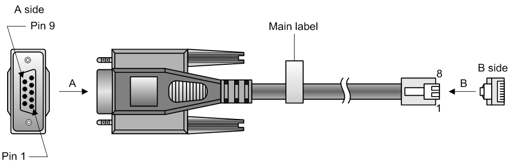
Table3-2 DB9-to-RJ45 console cable signal pinout
|
RJ-45 |
Signal |
DB-9 |
Signal |
|
1 |
RTS |
8 |
CTS |
|
2 |
DTR |
6 |
DSR |
|
3 |
TXD |
2 |
RXD |
|
4 |
SG |
5 |
SG |
|
5 |
SG |
5 |
SG |
|
6 |
RXD |
3 |
TXD |
|
7 |
DSR |
4 |
DTR |
|
8 |
CTS |
7 |
RTS |
To connect the switch to a configuration terminal (for example, a PC) by using a DB9-to-RJ45 console cable:
1. Plug the DB-9 female connector of the DB9-to-RJ45 console cable to the serial port on the PC.
2. Connect the RJ-45 connector to the serial console port on the switch.
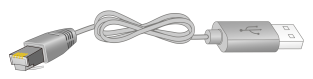
Connecting a USB-to-RJ45 console cable
|
|
IMPORTANT: · To use a USB-to-RJ45 console cable to connect the switch to a configuration terminal, first download and install the USB-to-RJ45 console driver on the configuration terminal and then connect the USB-to-RJ45 console cable to the configuration terminal. · If you have connected a USB-to-RJ45 console cable to the configuration terminal before by using driver, remove and reconnect the USB-to-RJ45 console cable to the configuration terminal after driver installation. |
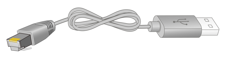
Figure3-3 USB-to-RJ45 console cable
The following installs the driver on the Windows system. To install the driver on other operating systems, see the installation guide in the driver compression package named by using the corresponding operating system.
To connect the switch to a configuration terminal by using a USB-to-RJ45 console cable:
1. Click the following link, or copy it to the address bar on your browser and download the USB-to-RJ45 console driver.
http://www.h3c.com/en/home/USB_to_RJ45_Console/
2. View the TXT file Read me in the Windows folder to check whether the Windows system of the configuration terminal supports the driver.
3. If the Windows system supports the driver, install PL23XX-M_LogoDriver_Setup_v200_20190815.exe.
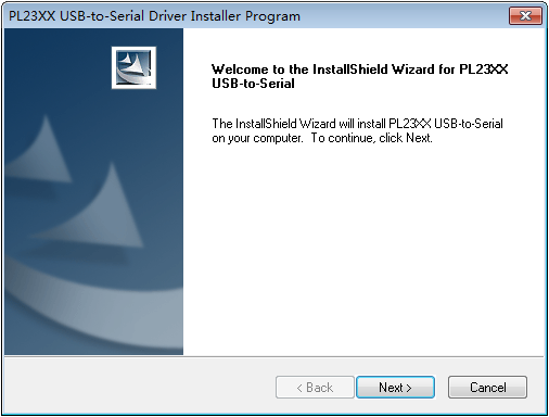
4. Click Next on the welcome page of the driver installation wizard.
Figure3-4 Driver installation wizard
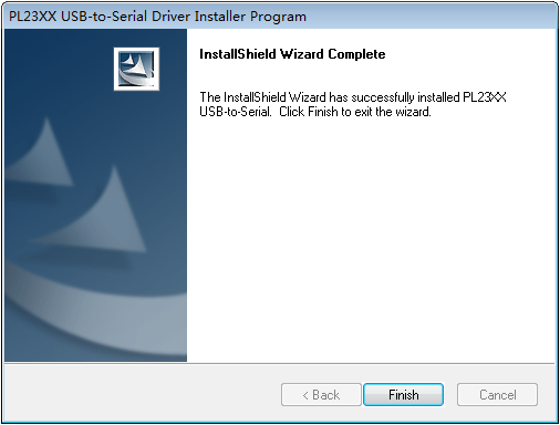
5. Click Finish after the drive installation is completed.
Figure3-5 Finishing the driver installation
6. Connect the standard USB connector of the cable to the USB port of the configuration terminal.
7. Connect the RJ-45 connector of the cable to the console port of the switch.
Setting terminal parameters
To configure and manage the switch through the console port, you must run a terminal emulator program, such as TeraTermPro, on your configuration terminal. You can use the emulator program to connect a network device, a Telnet site, or an SSH site. For more information about the terminal emulator programs, see the user guides for these programs.
Configure the terminal parameters as follows:
· Bits per second—9,600.
· Data bits—8.
· Parity—None.
· Stop bits—1.
· Flow control—None.
Powering on the switch
1. Before powering on the switch, verify that the following conditions are met:
¡ All fan tray slots have a fan tray installed.
¡ The power cord is correctly connected.
¡ The input power voltage meets the requirement of the switch.
¡ The console cable is correctly connected.
¡ The configuration terminal (a PC, for example) has started, and its serial port settings are consistent with the console port settings on the switch.
2. Power on the switch.
During the startup process, you can access Boot ROM menus to perform tasks such as software upgrade and file management. The Boot ROM interface and menu options differ with software versions. For more information about Boot ROM menu options, see the software-matching release notes for the device.
3. After the switch starts up, you can access the CLI to configure the switch.
For more information about the configuration commands, see the configuration guides and command references for the switch series.
4 Setting up an IRF fabric
You can use H3C IRF technology to connect and virtualize multiple S6812 series or S6813 series switches into a large virtual switch called an "IRF fabric" for flattened network topology, and high availability, scalability, and manageability. Only switches of the same series can form an IRF fabric.
IRF fabric setup flowchart
Figure4-1 IRF fabric setup flowchart
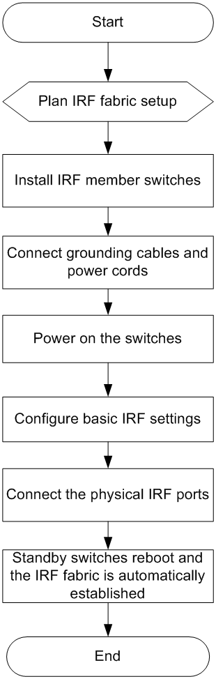
To set up an IRF fabric:
|
Step |
Description |
|
1. Plan IRF fabric setup. |
Plan the installation site and IRF fabric setup parameters: · Planning IRF fabric size and the installation site · Identifying the master switch and planning IRF member IDs · Planning IRF topology and connections |
|
2. Install IRF member switches. |
See "Installing the switch." |
|
3. Connect ground wires and power cords. |
See "Grounding the switch" and "Connecting the power cord." |
|
4. Power on the switches. |
N/A |
|
5. Configure basic IRF settings. |
See H3C S6812 & S6813 Switch Series Virtual Technologies Configuration Guide. |
|
6. Connect the physical IRF ports. |
Connect the physical IRF ports on switches. Use SFP+/QSFP28 transceiver modules and fibers for connections over long distances. Use SFP+/QSFP28 cables for connections over short distances. All switches except the master switch automatically reboot, and the IRF fabric is established. |
Planning IRF fabric setup
This section describes issues that an IRF fabric setup plan must cover.
Planning IRF fabric size and the installation site
Determine the number of required IRF member switches, depending on the user density and upstream bandwidth requirements. The switching capacity of an IRF fabric equals the total switching capacities of all member switches.
You can use switches of the same series or use switches of both the S6812 and S6813 series to form an IRF fabric.
Plan the installation site depending on your network solution as follows:
· Place all IRF member switches in one rack for centralized high-density access.
· Distribute the IRF member switches in different racks to implement the top-of-rack (ToR) access solution for a data center.
As your business grows, you can add member switches into the IRF fabric to increase the switching capacity without any topology change or replacement.
Identifying the master switch and planning IRF member IDs
Determine which switch you want to use as the master for managing all member switches in the IRF fabric. An IRF fabric has only one master switch. You configure and manage all member switches in the IRF fabric at the command line interface of the master switch.
|
|
NOTE: IRF member switches will automatically elect a master. You can affect the election result by assigning a high member priority to the intended master switch. For more information about master election, see H3C S6812 & S6813 Switch Series Virtual Technologies Configuration Guide. |
Prepare an IRF member ID assignment scheme. An IRF fabric uses member IDs to uniquely identify and manage its members, and you must assign each IRF member switch a unique member ID.
Planning IRF topology and connections
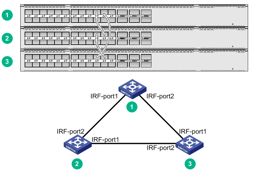
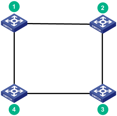
You can create an IRF fabric in daisy chain topology, or more reliably, ring topology. In ring topology, the failure of one IRF link does not cause the IRF fabric to split as in daisy chain topology. Rather, the IRF fabric changes to a daisy chain topology without interrupting network services.
You connect the IRF member switches through IRF ports, the logical interfaces for the connections between IRF member switches. Each IRF member switch has two IRF ports: IRF-port 1 and IRF-port 2. To use an IRF port, you must bind a minimum of one physical port to it.
When connecting two neighboring IRF member switches, you must connect the physical ports of IRF-port 1 on one switch to the physical ports of IRF-port 2 on the other switch.
The IRF port connections in the two figures are for illustration only, and more connection methods are available.
Figure4-2 IRF fabric in daisy chain topology
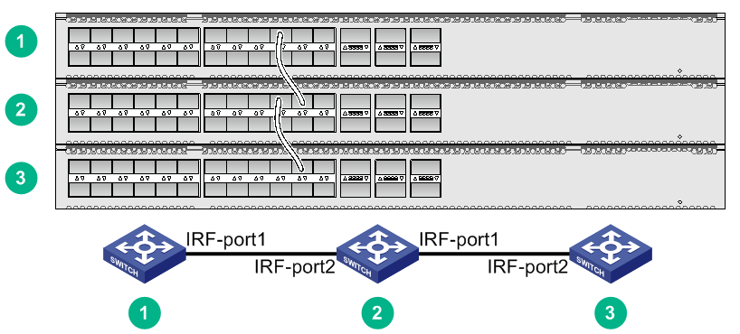
Figure4-3 IRF fabric in ring topology
You can set up IRF links between S6812/S6813 switches as follows:
· Use a QSFP28 module and fiber or a QSFP28 cable to connect QSFP28 ports for a 100-GE IRF physical connection.
· Use an SFP+ module and fiber or an SFP+ cable to connect SFP+ ports for a 10-GE IRF physical connection.
You can bind several ports to an IRF port for increased bandwidth and availability.
Identifying physical IRF ports on the member switches
Identify the physical IRF ports on the member switches according to your topology and connection scheme.
Table4-1 shows the physical ports that can be used for IRF connection and the port use restrictions.
Table4-1 Physical IRF port requirements
|
Chassis |
Candidate physical IRF ports |
Requirements |
|
· S6812-24X6C · S6812-48X6C · S6813-24X6C · S6813-48X6C |
All SFP+ ports and QSFP28 ports on the front panel |
· All physical ports to be bound to an IRF port must have the same data rate. · The port must operate at its highest speed. ¡ SFP+ port—10 Gbps ¡ QSFP28 port—100 Gbps |
Planning the cabling scheme
The cables available for connecting two peer IRF physical ports vary by port type:
· SFP+ ports—SFP+ transceiver modules and optical fibers or SFP+ cables. For the available transceiver modules and cables, see ports in Hardware Information and Specifications.
· QSFP28 ports—QSFP28 transceiver modules and optical fibers or QSFP28 cables. For the available transceiver modules and cables, see ports in Hardware Information and Specifications.
For a short-distance IRF connection in an equipment room, use an SFP+ cable or QSFP28 cable.
For a long-distance IRF connection, use SFP+/QSFP28 transceiver modules and optical fibers.
The following subsections describe several H3C recommended IRF connection schemes. All these schemes use a ring topology.
|
|
IMPORTANT: In these schemes, all physical IRF ports are located on the same side. If physical IRF ports are on different sides, you must measure the distance between them to select an appropriate cable. |
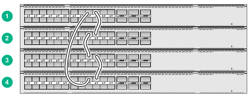
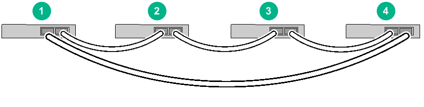
Connecting the IRF member switches in one rack
Figure4-4 shows an example for connecting four IRF member switches in a rack. The switches in the ring topology (see Figure4-5) are in the same order as connected in the rack.
Figure4-4 Connecting the switches in one rack
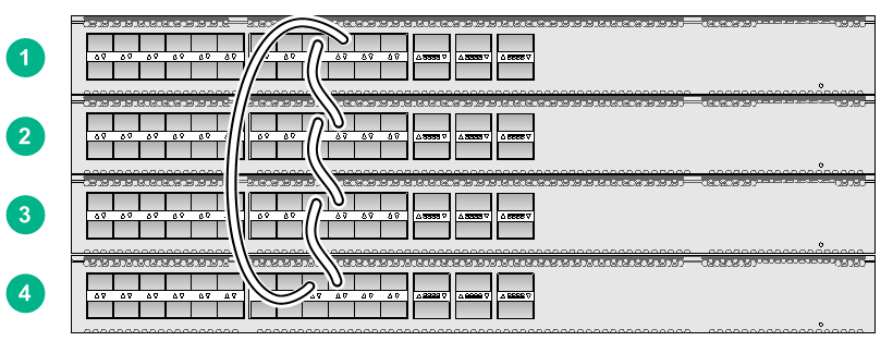
Connecting the IRF member switches in a ToR solution
You can install IRF member switches in different racks side by side to deploy a top of rack (ToR) solution.
Figure4-6 shows an example for connecting four top of rack IRF member switches. The topology is the same as Figure4-5.
Configuring basic IRF settings
After you install the IRF member switches, power on the switches, and log in to each IRF member switch (see H3C S6812 & S6813 Switch Series Fundamentals Configuration Guide) to configure their member IDs, member priorities, and IRF port bindings.
Follow these guidelines when you configure the switches:
· Assign the master switch higher member priority than any other switch.
· Bind physical ports to IRF port 1 on one switch and to IRF port 2 on the other switch. You perform IRF port binding before or after connecting IRF physical ports depending on the software release.
· Execute the display irf configuration command to verify the basic IRF settings.
For more information about configuring basic IRF settings, see H3C S6812 & S6813 Switch Series Virtual Technologies Configuration Guide.
Connecting the physical IRF ports
|
|
CAUTION: Wear an ESD wrist strap when you install transceiver modules, fibers, and cables. For more information, see the installation guide. |
Use SFP+/QSFP28 transceiver modules and fibers or SFP+/QSFP28 cables to connect the IRF member switches as planned.
Accessing the IRF fabric to verify the configuration
To verify the basic functionality of the IRF fabric after you finish configuring basic IRF settings and connecting IRF ports:
1. Log in to the IRF fabric through the console port of any member switch.
2. Create a Layer 3 interface, assign it an IP address, and make sure the IRF fabric and the remote network management station can reach each other.
3. Use Telnet or SNMP to access the IRF fabric from the network management station. (See H3C S6812 & S6813 Switch Series Fundamentals Configuration Guide.)
4. Verify that you can manage all member switches as if they were one node.
5. Display the running status of the IRF fabric by using the commands in Table4-2.
Table4-2 Displaying and maintaining IRF configuration and running status
|
Task |
Command |
|
Display information about the IRF fabric. |
display irf |
|
Display all members' IRF configurations. |
display irf configuration |
|
Display IRF fabric topology information. |
display irf topology |
|
|
NOTE: To avoid IP address collision and network problems, configure at least one multi-active detection (MAD) mechanism to detect the presence of multiple identical IRF fabrics and handle collisions. For more information about MAD detection, see H3C S6812 & S6813 Switch Series Virtual Technologies Configuration Guide. |
5 Maintenance and troubleshooting
Power module failure
The switch uses removable power modules. Examine the system status LED (SYS) of the switch to identify power module failure. For more information, see H3C S6812 & S6813 Switch Series Hardware Information and Specifications.
Symptom
The system status LED (SYS) is not steady green.
Solution
To resolve the issue:
1. Verify that the switch power cord is correctly connected.
2. Verify that the power source meets the requirement.
3. Verify that the operating temperature of the switch is in an acceptable range and the power module has good ventilation.
4. If the issue persists, contact H3C Support.
5. To replace a failed power module, see "Installing and removing a power module."
Fan tray failure
|
|
WARNING! Do not remove multiple fan trays simultaneously. You can remove another fan tray only after you finish replacing one fan tray. Make sure you finish replacing a fan tray within 3 minutes. |
The switch uses removable fan trays. Examine the system status LED of the switch and the fan tray status LED to identify fan tray failure.
Symptom
The status LED on a fan tray is flashing yellow or off.
Solution
See "Installing and removing a fan tray" to replace a failed fan tray. If the issue persists, contact H3C Support.
Configuration terminal display problems
No display
Symptom
The configuration terminal displays nothing when the switch is powered on.
Solution
To resolve the issue:
1. Verify that the power system is operating correctly.
2. Verify that the console cable is connected correctly.
3. Verify that the console cable does not have any problems and the terminal settings are correct.
4. If the issue persists, contact H3C Support.
Garbled display
Symptom
The configuration terminal has a garbled display.
Solution
To resolve the issue:
1. Verify that the following settings are configured for the terminal:
¡ Baud rate—9,600.
¡ Data bits—8.
¡ Parity—None.
¡ Stop bits—1.
¡ Flow control—None.
2. If the issue persists, contact H3C Support.
