- Table of Contents
-
- 06-IP Multicast Configuration Guide
- 00-Preface
- 01-Multicast overview
- 02-IGMP snooping configuration
- 03-PIM snooping configuration
- 04-Multicast VLAN configuration
- 05-Multicast routing and forwarding configuration
- 06-IGMP configuration
- 07-PIM configuration
- 08-MSDP configuration
- 09-Multicast VPN configuration
- 10-MLD snooping configuration
- 11-IPv6 PIM snooping configuration
- 12-IPv6 multicast VLAN configuration
- 13-IPv6 multicast routing and forwarding configuration
- 14-MLD configuration
- 15-IPv6 PIM configuration
- Related Documents
-
| Title | Size | Download |
|---|---|---|
| 02-IGMP snooping configuration | 458.77 KB |
IGMP snooping configuration task list
IGMP snooping configuration task list for VLANs
IGMP configuration task list for VSIs
Configuring basic IGMP snooping features
Specifying an IGMP snooping version
Setting the maximum number of IGMP snooping forwarding entries
Configuring static multicast MAC address entries
Setting the IGMP last member query interval
Configuring IGMP snooping port features
Setting aging timers for dynamic ports
Configuring a port as a simulated member host
Enabling fast-leave processing
Disabling a port from becoming a dynamic router port
Configuring the IGMP snooping querier
Enabling the IGMP snooping querier
Enabling IGMP snooping querier election
Configuring parameters for IGMP general queries and responses
Specifying the Layer 2 multicast forwarding mode
Enabling IGMP snooping proxying
Configuring parameters for IGMP messages
Configuring source IP addresses for IGMP messages
Setting the 802.1p priority for IGMP messages
Configuring IGMP snooping policies
Configuring a multicast group policy
Enabling multicast source port filtering
Enabling dropping unknown multicast data
Enabling IGMP report suppression
Setting the maximum number of multicast groups on a port
Enabling multicast group replacement
Configuring an IGMP snooping user access control policy
Setting the DSCP value for outgoing IGMP snooping protocol packets
Displaying and maintaining IGMP snooping
IGMP snooping configuration examples
Group policy and simulated joining configuration example(for VLANs)
Static port configuration example (for VLANs)
IGMP snooping querier configuration example (for VLANs)
IGMP snooping proxying configuration example (for VLANs)
IGMP snooping configuration example (for VSIs)
IGMP snooping configuration example (for VXLANs)
Layer 2 multicast forwarding cannot function
Multicast group policy does not work
Configuring IGMP snooping
Overview
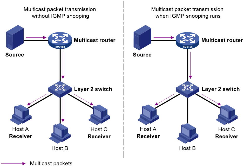
IGMP snooping runs on a Layer 2 device as a multicast constraining mechanism to improve multicast forwarding efficiency. It creates Layer 2 multicast forwarding entries from IGMP packets that are exchanged between the hosts and the router.
As shown in Figure 1, when IGMP snooping is not enabled, the Layer 2 switch floods multicast packets to all hosts in a VLAN or VSI. When IGMP snooping is enabled, the Layer 2 switch forwards multicast packets of known multicast groups to only the receivers.
Figure 1 Multicast packet transmission without and with IGMP snooping
IGMP snooping ports
As shown in Figure 2, IGMP snooping runs on Switch A and Switch B, and Host A and Host C are receivers in a multicast group. IGMP snooping ports are divided into member ports and router ports.
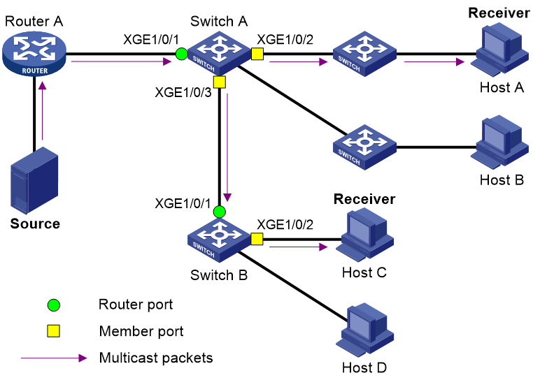
Router ports
On an IGMP snooping Layer 2 device, the ports toward Layer 3 multicast devices are called router ports. In Figure 2, Ten-GigabitEthernet 1/0/1 of Switch A and Ten-GigabitEthernet 1/0/1 of Switch B are router ports.
Router ports contain the following types:
· Dynamic router port—When a port receives an IGMP general query whose source address is not 0.0.0.0 or receives a PIM hello message, the port is added into the dynamic router port list. At the same time, an aging timer is started for the port. If the port receives either of the messages before the timer expires, the timer is reset. If the port does not receive either of the messages when the timer expires, the port is removed from the dynamic router port list.
· Static router port—When a port is statically configured as a router port, it is added into the static router port list. The static router port does not age out, and it can be deleted only manually.
Do not confuse the "router port" in IGMP snooping with the "routed interface" commonly known as the "Layer 3 interface." The router port in IGMP snooping is a Layer 2 interface.
Member ports
On an IGMP snooping Layer 2 device, the ports toward receiver hosts are called member ports. In Figure 2, Ten-GigabitEthernet 1/0/2 and Ten-GigabitEthernet 1/0/3 of Switch A and Ten-GigabitEthernet 1/0/2 of Switch B are member ports.
Member ports contain the following types:
· Dynamic member port—When a port receives an IGMP report, it is added to the associated dynamic IGMP snooping forwarding entry as an outgoing interface. At the same time, an aging timer is started for the port. If the port receives an IGMP report before the timer expires, the timer is reset. If the port does not receive an IGMP report when the timer expires, the port is removed from the associated dynamic forwarding entry.
· Static member port—When a port is statically configured as a member port, it is added to the associated static IGMP snooping forwarding entry as an outgoing interface. The static member port does not age out, and it can be deleted only manually.
Unless otherwise specified, router ports and member ports in this document include both static and dynamic router ports and member ports.
How IGMP snooping works
The ports in this section are dynamic ports. For information about how to configure and remove static ports, see "Configuring static ports."
IGMP messages types include general query, IGMP report, and leave message. An IGMP snooping-enabled Layer 2 device performs differently depending on the message types.
General query
The IGMP querier periodically sends IGMP general queries to all hosts and routers on the local subnet to check for the existence of multicast group members.
After receiving an IGMP general query, the Layer 2 device forwards the query to all ports in the VLAN or VSI except the receiving port. The Layer 2 device also performs one of the following actions:
· If the receiving port is a dynamic router port in the dynamic router port list, the Layer 2 device restarts the aging timer for the port.
· If the receiving port does not exist in the dynamic router port list, the Layer 2 device adds the port to the dynamic router port list. It also starts an aging timer for the port.
IGMP report
A host sends an IGMP report to the IGMP querier for the following purposes:
· Responds to queries if the host is a multicast group member.
· Applies for a multicast group membership.
After receiving an IGMP report from a host, the Layer 2 device forwards the report through all the router ports in the VLAN or VSI. It also resolves the address of the reported multicast group, and looks up the forwarding table for a matching entry as follows:
· If no match is found, the Layer 2 device creates a forwarding entry with the receiving port as an outgoing interface. It also marks the receiving port as a dynamic member port and starts an aging timer for the port.
· If a match is found but the matching forwarding entry does not contain the receiving port, the Layer 2 device adds the receiving port to the outgoing interface list. It also marks the receiving port as a dynamic member port and starts an aging timer for the port.
· If a match is found and the matching forwarding entry contains the receiving port, the Layer 2 device restarts the aging timer for the port.
In an application with a group policy configured on an IGMP snooping-enabled Layer 2 device, when a user requests a multicast program, the user's host initiates an IGMP report. After receiving this report, the Layer 2 device resolves the multicast group address in the report and performs ACL filtering on the report. If the report passes ACL filtering, the Layer 2 device creates an IGMP snooping forwarding entry for the multicast group with the receiving port as an outgoing interface. If the report does not pass ACL filtering, the Layer 2 device drops this report. The multicast data for the multicast group is not sent to this port, and the user cannot retrieve the program.
A Layer 2 device does not forward an IGMP report through a non-router port because of the host IGMP report suppression mechanism. For more information about the IGMP report suppression mechanism, see "Configuring IGMP."
Leave message
An IGMPv1 receiver host does not send any leave messages when it leaves a multicast group. The Layer 2 device cannot immediately update the status of the port that connects to the receiver host. The Layer 2 device does not remove the port from the outgoing interface list in the associated forwarding entry until the aging time for the group expires.
An IGMPv2 or IGMPv3 host sends an IGMP leave message when it leaves a multicast group.
When the Layer 2 device receives an IGMP leave message on a dynamic member port, the Layer 2 device first examines whether a forwarding entry matches the group address in the message.
· If no match is found, the Layer 2 device discards the IGMP leave message.
· If a match is found but the receiving port is not an outgoing interface in the forwarding entry, the Layer 2 device discards the IGMP leave message.
· If a match is found and the receiving port is not the only outgoing interface in the forwarding entry, the Layer 2 device performs the following actions:
¡ Discards the IGMP leave message.
¡ Sends an IGMP group-specific query to identify whether the group has active receivers attached to the receiving port.
¡ Sets the aging timer for the receiving port to twice the IGMP last member query interval.
· If a match is found and the receiving port is the only outgoing interface in the forwarding entry, the Layer 2 device performs the following actions:
¡ Forwards the IGMP leave message to all router ports in the VLAN or VSI.
¡ Sends an IGMP group-specific query to identify whether the group has active receivers attached to the receiving port.
¡ Sets the aging timer for the receiving port to twice the IGMP last member query interval.
After receiving the IGMP leave message on a port, the IGMP querier resolves the multicast group address in the message. Then, it sends an IGMP group-specific query to the multicast group through the receiving port.
After receiving the IGMP group-specific query, the Layer 2 device forwards the query through all router ports and member ports of the group in the VLAN or VSI. Then, it waits for the responding IGMP report from the directly connected hosts. For the dynamic member port that received the leave message, the Layer 2 device also performs one of the following actions:
· If the port receives an IGMP report before the aging timer expires, the Layer 2 device resets the aging timer.
· If the port does not receive an IGMP report when the aging timer expires, the Layer 2 device removes the port from the forwarding entry for the multicast group.
IGMP snooping proxying
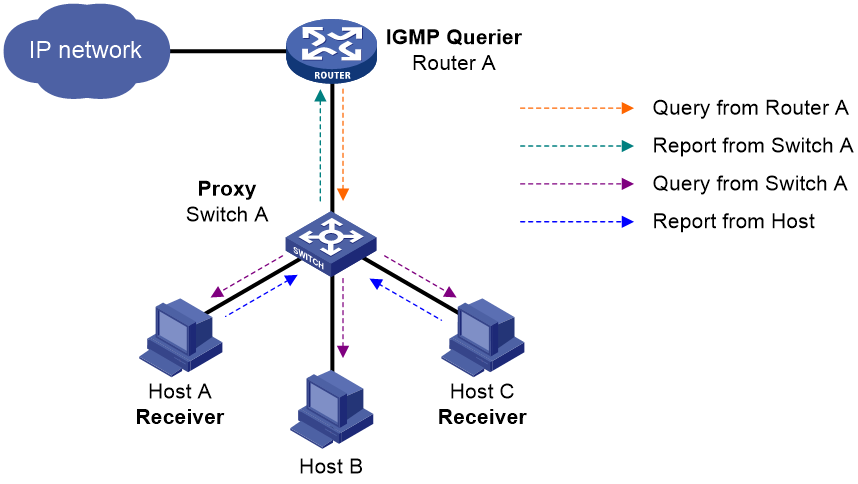
As shown in Figure 3, to reduce the number of IGMP report and leave messages received by the upstream device, you can enable IGMP snooping proxying on the edge device. With IGMP snooping proxying enabled, the edge device acts as a host for the upstream IGMP snooping querier to send IGMP report and leave messages to Router A. The host IGMP report suppression mechanism on the edge device does not take effect. For more information about the IGMP report suppression mechanism, see "Configuring IGMP."
Figure 3 IGMP snooping proxying
The IGMP snooping proxy device processes different IGMP messages as follows:
· General query.
After receiving an IGMP general query, the device forwards the query to all ports in the VLAN except the receiving port. The device also generates an IGMP report based on the local membership information and sends the report to all router ports.
· Group-specific query or group-and-source-specific query.
After receiving an IGMP group-specific query or group-and-source-specific query, the device forwards the query to all ports in the VLAN except the receiving port. If the forwarding entry has a member port, the device sends a report to all router ports in the VLAN.
· Report.
After receiving an IGMP report from a host, the device looks up the forwarding table for a matching entry as follows:
¡ If a match is found and the matching forwarding entry contains the receiving port, the device resets the aging timer for the port.
¡ If a match is found but the matching forwarding entry does not contain the receiving port, the device adds the receiving port to the outgoing interface list. It also marks the receiving port as a dynamic member port and starts an aging timer for the port.
¡ If no match is found, the device creates a forwarding entry with the receiving port as an outgoing interface. It also marks the receiving port as a dynamic member port and starts an aging timer for the port. Then it sends the report to all router ports.
· Leave message.
After receiving the IGMP leave message on a port, the device sends an IGMP group-specific query through the receiving port. The device sends the IGMP leave message to all router ports only when the last member port is removed from the forwarding entry.
Protocols and standards
RFC 4541, Considerations for Internet Group Management Protocol (IGMP) and Multicast Listener Discovery (MLD) Snooping Switches
IGMP snooping configuration task list
You can configure IGMP snooping for VLANs or VSIs.
IGMP snooping configuration task list for VLANs
IGMP configuration task list for VSIs
|
Tasks at a glance |
|
Configuring basic IGMP snooping features: · (Required.) Enabling IGMP snooping · (Optional.) Specifying an IGMP snooping version · (Optional.) Setting the maximum number of IGMP snooping forwarding entries · (Optional.) Setting the IGMP last member query interval |
|
(Optional.) Setting aging timers for dynamic ports |
|
(Optional.) Configuring the IGMP snooping querier: · Enabling the IGMP snooping querier · Enabling IGMP snooping querier election · Configuring parameters for IGMP general queries and responses |
|
(Optional.) Specifying the Layer 2 multicast forwarding mode |
|
(Optional.) Enabling IGMP snooping proxying |
|
(Optional.) Configuring parameters for IGMP messages: |
|
(Optional.) Configuring IGMP snooping policies: |
|
(Optional.) Setting the DSCP value for outgoing IGMP snooping protocol packets |
For IGMP reports received from secondary VLANs, the relevant IGMP snooping forwarding entries are maintained by the primary VLAN. Therefore, you need to enable IGMP snooping only for the primary VLAN. The IGMP snooping configuration made in secondary VLANs does not take effect. For more information about primary VLANs and secondary VLANs, see Layer 2—LAN Switching Configuration Guide.
The IGMP snooping configurations made on Layer 2 aggregate interfaces do not interfere with the configurations made on member ports. In addition, the configurations made on Layer 2 aggregate interfaces do not take part in aggregation calculations. The configuration made on a member port of the aggregate group takes effect after the port leaves the aggregate group.
Configuring basic IGMP snooping features
Before you configure basic IGMP snooping features, complete the following tasks:
· Configure VLANs or VSIs.
· Determine the IGMP snooping version.
· Determine the maximum number of IGMP snooping forwarding entries.
· Determine the IGMP last member query interval.
Enabling IGMP snooping
When you enable IGMP snooping, follow these restrictions and guidelines:
· You must enable the IGMP snooping feature by using the igmp-snooping command before you enable IGMP snooping globally or for VLANs or VSIs.
· IGMP snooping configuration made in VLAN view or VSI view takes effect only on the member ports in that VLAN or VSI.
· You can enable IGMP snooping for multiple VLANs by using the enable vlan command in IGMP-snooping view or for a VLAN by using the igmp-snooping enable command in VLAN view. The configuration in VLAN view has the same priority as the configuration in IGMP-snooping view, and the most recent configuration takes effect.
· To configure other IGMP snooping features for VLANs or VSIs, you must enable IGMP snooping for the specific VLANs or VSIs even though IGMP snooping is globally enabled. The IGMP snooping configuration for specific VLANs or VSIs takes priority over the global IGMP snooping configuration.
· The IGMP snooping status on all devices in a VSI must be the same.
Enabling IGMP snooping globally
|
Step |
Command |
Remarks |
|
1. Enter system view. |
system-view |
N/A |
|
2. Enable the IGMP snooping feature and enter IGMP-snooping view. |
igmp-snooping |
By default, the IGMP snooping feature is disabled. |
|
3. Enable IGMP snooping globally. |
global-enable |
By default, IGMP snooping is disabled globally. |
Enabling IGMP snooping for multiple VLANs
|
Step |
Command |
Remarks |
|
1. Enter system view. |
system-view |
N/A |
|
2. Enable the IGMP snooping feature and enter IGMP-snooping view. |
igmp-snooping |
By default, the IGMP snooping feature is disabled. |
|
3. Enable IGMP snooping for multiple VLANs. |
enable vlan vlan-list |
By default, the IGMP snooping status in a VLAN is consistent with the global IGMP snooping status. |
Enabling IGMP snooping for a VLAN or VSI
|
Step |
Command |
Remarks |
|
1. Enter system view. |
system-view |
N/A |
|
2. Enable the IGMP snooping feature and enter IGMP-snooping view. |
igmp-snooping |
By default, the IGMP snooping feature is disabled. |
|
3. Return to system view. |
quit |
N/A |
|
4. Enter VLAN or VSI view. |
· Enter VLAN view: · Enter VSI view: |
N/A |
|
5. Enable IGMP snooping for the VLAN or VSI. |
igmp-snooping enable |
By default, the IGMP snooping status in a VLAN or VSI is consistent with the global IGMP snooping status. |
|
6. (Optional.) Disable IGMP snooping for the VLAN or VSI. |
igmp-snooping disable |
By default, the IGMP snooping status in a VLAN or VSI is consistent with the global IGMP snooping status. |
Specifying an IGMP snooping version
Different IGMP snooping versions process different versions of IGMP messages.
· IGMPv2 snooping processes IGMPv1 and IGMPv2 messages, but it floods IGMPv3 messages in the VLAN instead of processing them.
· IGMPv3 snooping processes IGMPv1, IGMPv2, and IGMPv3 messages.
If you change IGMPv3 snooping to IGMPv2 snooping, the device performs the following actions:
· Clears all IGMP snooping forwarding entries that are dynamically added.
· Keeps static IGMPv3 snooping forwarding entries (*, G).
· Clears static IGMPv3 snooping forwarding entries (S, G), which will be restored when IGMP snooping is switched back to IGMPv3 snooping.
For more information about static IGMP snooping forwarding entries, see "Configuring static ports."
You can specify the version for the specified VLANs in IGMP-snooping view, for a VSI in VSI view, or for a VLAN in VLAN view. For a VLAN, the configuration in VLAN view has the same priority as the configuration in IGMP-snooping view, and the most recent configuration takes effect.
Specifying an IGMP snooping version in IGMP-snooping view
|
Step |
Command |
Remarks |
|
1. Enter system view. |
system-view |
N/A |
|
2. Enable the IGMP snooping feature and enter IGMP-snooping view. |
igmp-snooping |
N/A |
|
3. Specify an IGMP snooping version for the specified VLANs. |
version version-number vlan vlan-list |
The default setting is 2. |
Specifying an IGMP snooping version in VLAN or VSI view
|
Step |
Command |
Remarks |
|
1. Enter system view. |
system-view |
N/A |
|
2. Enter VLAN view or VSI view. |
· Enter VLAN view: · Enter VSI view: |
N/A |
|
3. Specify an IGMP snooping version for the VLAN or VSI. |
igmp-snooping version version-number |
The default setting is 2. |
Setting the maximum number of IGMP snooping forwarding entries
You can modify the maximum number of IGMP snooping forwarding entries, including dynamic entries and static entries. When the number of forwarding entries on the device reaches the upper limit, the device does not automatically remove any existing entries. To allow new entries to be created, remove some entries manually.
To set the maximum number of IGMP snooping forwarding entries:
|
Step |
Command |
Remarks |
|
1. Enter system view. |
system-view |
N/A |
|
2. Enter IGMP-snooping view. |
igmp-snooping |
N/A |
|
3. Set the maximum number of IGMP snooping forwarding entries. |
entry-limit limit |
The default setting is 4294967295. |
Configuring static multicast MAC address entries
In Layer 2 multicast, multicast MAC address entries can be dynamically created through Layer 2 multicast protocols (such as IGMP snooping). You can also manually configure static multicast MAC address entries by binding multicast MAC addresses and ports to control the destination ports of the multicast data.
Configuration restrictions and guidelines
When you configure static multicast MAC address entries, follow these restrictions and guidelines:
· You do not need to enable IP multicast routing before this configuration.
· You must specify an unused multicast MAC address when configuring a static multicast MAC address entry. A multicast MAC address is a MAC address in which the least significant bit of the most significant octet is 1.
· You can configure static multicast MAC address entries on the specified interfaces in system view or on the current interface in interface view.
Configuring a static multicast MAC address entry in system view
|
Step |
Command |
Remarks |
|
1. Enter system view. |
system-view |
N/A |
|
2. Configure a static multicast MAC address entry. |
mac-address multicast mac-address interface interface-list vlan vlan-id |
By default, no static multicast MAC address entries exist. |
Configuring a static multicast MAC address entry in interface view
|
Step |
Command |
Remarks |
|
1. Enter system view. |
system-view |
N/A |
|
2. Enter Layer 2 Ethernet interface or Layer 2 aggregate interface view. |
interface interface-type interface-number |
N/A |
|
3. Configure a static multicast MAC address entry. |
mac-address multicast mac-address vlan vlan-id |
By default, no static multicast MAC address entries exist. |
Setting the IGMP last member query interval
A receiver host starts a report delay timer for a multicast group when it receives an IGMP group-specific query for the group. This timer is set to a random value in the range of 0 to the maximum response time advertised in the query. When the timer value decreases to 0, the host sends an IGMP report to the group.
The IGMP last member query interval defines the maximum response time advertised in IGMP group-specific queries. Set an appropriate value for the IGMP last member query interval to speed up hosts' responses to IGMP group-specific queries and avoid IGMP report traffic bursts.
Configuration restrictions and guidelines
When you set the IGMP last member query interval, follow these restrictions and guidelines:
· The Layer 2 device does not send an IGMP group-specific query if it receives an IGMP leave message from a port enabled with fast-leave processing.
· You can set the IGMP last member query interval globally for all VLANs and VSIs in IGMP-snooping view, for a VSI in VSI view, or for a VLAN in VLAN view. For a VSI, the VSI-specific configuration takes priority over the global configuration. For a VLAN, the VLAN-specific configuration takes priority over the global configuration.
Setting the IGMP last member query interval globally
|
Step |
Command |
Remarks |
|
1. Enter system view. |
system-view |
N/A |
|
2. Enter IGMP-snooping view. |
igmp-snooping |
N/A |
|
3. Set the IGMP last member query interval globally. |
last-member-query-interval interval |
The default setting is 1 second. |
Setting the IGMP last member query interval in a VLAN or VSI
|
Step |
Command |
Remarks |
|
1. Enter system view. |
system-view |
N/A |
|
2. Enter VLAN view or VSI view. |
· Enter VLAN view: · Enter VSI view: |
N/A |
|
3. Set the IGMP last member query interval for the VLAN or VSI. |
igmp-snooping last-member-query-interval interval |
The default setting is 1 second. |
Configuring IGMP snooping port features
Before you configure IGMP snooping port features, complete the following tasks:
· Enable IGMP snooping for the VLAN or VSI.
· Determine the aging timer for dynamic router ports.
· Determine the aging timer for dynamic member ports.
· Determine the addresses of the multicast group and multicast source.
Setting aging timers for dynamic ports
When you set aging timers for dynamic ports, follow these restrictions and guidelines:
· If the memberships of multicast groups frequently change, you can set a relatively small value for the aging timer of the dynamic member ports. If the memberships of multicast groups rarely change, you can set a relatively large value.
· If a dynamic router port receives a PIMv2 hello message, the aging timer for the port is specified by the hello message. In this case, the router-aging-time or igmp-snooping router-aging-time command does not take effect on the port.
· IGMP group-specific queries originated by the Layer 2 device trigger the adjustment of aging timers for dynamic member ports. If a dynamic member port receives such a query, its aging timer is set to twice the IGMP last member query interval. For more information about setting the IGMP last member query interval on the Layer 2 device, see "Setting the IGMP last member query interval."
· You can set the timers globally for all VLANs and VSIs in IGMP-snooping view, for a VSI in VSI view, or for a VLAN in VLAN view. For a VLAN, the VLAN-specific configuration takes priority over the global configuration. For a VSI, the VSI-specific configuration takes priority over the global configuration.
Setting the aging timers for dynamic ports globally
|
Step |
Command |
Remarks |
|
1. Enter system view. |
system-view |
N/A |
|
2. Enter IGMP-snooping view. |
igmp-snooping |
N/A |
|
3. Set the aging timer for dynamic router ports globally. |
router-aging-time seconds |
The default setting is 260 seconds. |
|
4. Set the global aging timer for dynamic member ports globally. |
host-aging-time seconds |
The default setting is 260 seconds. |
Setting the aging timers for dynamic ports in a VLAN or VSI
|
Step |
Command |
Remarks |
|
1. Enter system view. |
system-view |
N/A |
|
2. Enter VLAN view or VSI view. |
· Enter VLAN view: · Enter VSI view: |
N/A |
|
3. Set the aging timer for dynamic router ports in the VLAN or VSI. |
igmp-snooping router-aging-time seconds |
The default setting is 260 seconds. |
|
4. Set the aging timer for dynamic member ports in the VLAN or VSI. |
igmp-snooping host-aging-time seconds |
The default setting is 260 seconds. |
Configuring static ports
You can configure the following types of static ports:
· Static member port—When you configure a port as a static member port for a multicast group, all hosts attached to the port will receive multicast data for the group.
The static member port does not respond to IGMP queries. When you complete or cancel this configuration on a port, the port does not send an unsolicited IGMP report or leave message.
· Static router port—When you configure a port as a static router port for a multicast group, all multicast data for the group received on the port will be forwarded.
To configure a port as a static port:
|
Step |
Command |
Remarks |
|
1. Enter system view. |
system-view |
N/A |
|
2. Enter Layer 2 Ethernet interface view or Layer 2 aggregate interface view. |
interface interface-type interface-number |
N/A |
|
3. Configure the port as a static port. |
· Configure the port as a static member port: · Configure the port as a static router port: |
By default, a port is not a static member port or a static router port. |
Configuring a port as a simulated member host
When a port is configured as a simulated member host, it is equivalent to an independent host in the following ways:
· It sends an unsolicited IGMP report when you complete the configuration.
· It responds to IGMP general queries with IGMP reports.
· It sends an IGMP leave message when you cancel the configuration.
The version of IGMP running on the simulated member host is the same as the version of IGMP snooping running on the port. The port ages out in the same way as a dynamic member port.
To configure a port as a simulated member host:
|
Step |
Command |
Remarks |
|
1. Enter system view. |
system-view |
N/A |
|
2. Enter Layer 2 Ethernet interface view or Layer 2 aggregate interface view. |
interface interface-type interface-number |
N/A |
|
3. Configure the port as a simulated member host. |
igmp-snooping host-join group-address [ source-ip source-address ] vlan vlan-id |
By default, the port is not a simulated member host. |
Enabling fast-leave processing
This feature enables the device to immediately remove a port from the forwarding entry for a multicast group when the port receives a leave massage.
Configuration restrictions and guidelines
When you enable fast-leave processing, follow these restrictions and guidelines:
· Do not enable fast-leave processing on a port that has multiple receiver hosts in a VLAN. If fast-leave processing is enabled, the remaining receivers cannot receive multicast data for a group after a receiver leaves that group.
Enabling fast-leave processing globally
|
Step |
Command |
Remarks |
|
1. Enter system view. |
system-view |
N/A |
|
2. Enter IGMP-snooping view. |
igmp-snooping |
N/A |
|
3. Enable fast-leave processing globally. |
fast-leave [ vlan vlan-list ] |
By default, fast-leave processing is disabled globally. |
Enabling fast-leave processing on a port
|
Step |
Command |
Remarks |
|
1. Enter system view. |
system-view |
N/A |
|
2. Enter Layer 2 Ethernet interface view or Layer 2 aggregate interface view. |
interface interface-type interface-number |
N/A |
|
3. Enable fast-leave processing on the port. |
igmp-snooping fast-leave [ vlan vlan-list ] |
By default, fast-leave processing is disabled on a port. |
Disabling a port from becoming a dynamic router port
A receiver host might send IGMP general queries or PIM hello messages for testing purposes. On the Layer 2 device, the port that receives either of the messages becomes a dynamic router port. Before the aging timer for the port expires, the following problems might occur:
· All multicast data for the VLAN to which the port belongs flows to the port. Then, the port forwards the data to attached receiver hosts. The receiver hosts will receive multicast data that it does not want to receive.
· The port forwards the IGMP general queries or PIM hello messages to its upstream multicast routers. These messages might affect the multicast routing protocol state (such as the IGMP querier or DR election) on the multicast routers. This might further cause network interruption.
To solve these problems, you can disable a port from becoming a dynamic router port. This also improves network security and the control over receiver hosts.
To disable a port from becoming a dynamic router port:
|
Step |
Command |
Remarks |
|
1. Enter system view. |
system-view |
N/A |
|
2. Enter Layer 2 Ethernet interface view or Layer 2 aggregate interface view. |
interface interface-type interface-number |
N/A |
|
3. Disable the port from becoming a dynamic router port. |
igmp-snooping router-port-deny [ vlan vlan-list ] |
By default, a port is allowed to become a dynamic router port. This configuration does not affect the static router port configuration. |
Configuring the IGMP snooping querier
This section describes how to configure an IGMP snooping querier.
Configuration prerequisites
Before you configure the IGMP snooping querier, complete the following tasks:
· Enable IGMP snooping for the VLAN or VSI.
· Determine the IGMP general query interval.
· Determine the maximum response time for IGMP general queries.
Enabling the IGMP snooping querier
Configuration restrictions and guidelines
When you enable the IGMP snooping querier, follow these restrictions and guidelines:
· Do not enable the IGMP snooping querier on a multicast network that runs IGMP. An IGMP snooping querier does not take part in IGMP querier elections. However, it might affect IGMP querier elections if it sends IGMP general queries with a low source IP address.
· On a TRILL network, if an RB acts as both the IGMP snooping querier and the AVF of a VLAN, configure the appointed port as a static router port. This configuration ensures that IGMP snooping forwarding entries can be created. For more information about TRILL, RBs, AVFs, and appointed ports, see TRILL Configuration Guide.
· On a VXLAN network, the IGMP snooping querier in a VSI does not include VLAN tags in IGMP general queries. As a best practice, do not enable the IGMP snooping querier in a VSI if the VSI uses the Ethernet access mode. For more information about the Ethernet access mode, see VXLAN Configuration Guide.
Configuration procedure
To enable the IGMP snooping querier for a VLAN or VSI:
|
Step |
Command |
Remarks |
|
1. Enter system view. |
system-view |
N/A |
|
2. Enter VLAN view or VSI view. |
· Enter VLAN view: · Enter VSI view: |
N/A |
|
3. Enable the IGMP snooping querier. |
igmp-snooping querier |
By default, the IGMP snooping querier is disabled. |
Enabling IGMP snooping querier election
To avoid traffic interruption caused by the failure of a single querier in a VLAN or VSI, configure multiple queriers in the VLAN or VSI and enable querier election. When the elected querier fails, a new querier election starts to ensure multicast forwarding. IGMP snooping querier election has the same mechanism as IGMP querier election. For more information about IGMP querier election, see "Configuring IGMP".
Configuration prerequisites
Before you enable IGMP snooping querier election for a VLAN or VSI, complete the following tasks:
· Enable the IGMP snooping querier for the VLAN or VSI.
· Configure the source IP address for IGMP general queries as an IP address different from 0.0.0.0 and the local querier IP address. An IGMP snooping querier performs querier election only if the source IP address of a received IGMP general query is not 0.0.0.0 or its own IP address. To configure the source IP address for IGMP general queries, use the igmp-snooping general-query source-ip command.
· Make sure the candidate IGMP snooping queriers run the same IGMP snooping version. To specify the IGMP snooping version, use the igmp-snooping version command.
Configuration procedure
To enable IGMP snooping querier election:
|
Step |
Command |
Remarks |
|
1. Enter system view. |
system-view |
N/A |
|
2. Enter VLAN or VSI view. |
· Enter VLAN view: · Enter VSI view: |
N/A |
|
3. Enable the IGMP snooping querier. |
igmp-snooping querier |
By default, the IGMP snooping querier is disabled. |
|
4. Enable IGMP snooping querier election. |
igmp-snooping querier-election |
By default, IGMP snooping querier election is disabled. |
Configuring parameters for IGMP general queries and responses
|
|
CAUTION: To avoid mistakenly deleting multicast group members, make sure the IGMP general query interval is greater than the maximum response time for IGMP general queries. |
You can modify the IGMP general query interval for a VLAN or VSI based on the actual condition of the network.
A receiver host starts a report delay timer for each multicast group that it has joined when it receives an IGMP general query. This timer is set to a random value in the range of 0 to the maximum response time advertised in the query. When the timer value decreases to 0, the host sends an IGMP report to the corresponding multicast group.
Set an appropriate value for the maximum response time for IGMP general queries to speed up hosts' responses to IGMP general queries and avoid IGMP report traffic bursts.
You can set the maximum response time for IGMP general queries globally for all VLANs and VSIs in IGMP-snooping view, for a VSI in VSI view, or for a VLAN in VLAN view. For a VSI, the VSI-specific configuration takes priority over the global configuration. For a VLAN, the VLAN-specific configuration takes priority over the global configuration.
Configuring parameters for IGMP general queries and responses globally
|
Step |
Command |
Remarks |
|
1. Enter system view. |
system-view |
N/A |
|
2. Enter IGMP-snooping view. |
igmp-snooping |
N/A |
|
3. Set the maximum response time for IGMP general queries. |
max-response-time seconds |
The default setting is 10 seconds. |
Configuring parameters for IGMP general queries and responses in a VLAN or VSI
|
Step |
Command |
Remarks |
|
1. Enter system view. |
system-view |
N/A |
|
2. Enter VLAN view or VSI view. |
· Enter VLAN view: · Enter VSI view: |
N/A |
|
3. Set the IGMP general query interval in the VLAN or VSI. |
igmp-snooping query-interval interval |
The default setting is 125 seconds. |
|
4. Set the maximum response time for IGMP general queries in the VLAN or VSI. |
igmp-snooping max-response-time seconds |
The default setting is 10 seconds. |
Specifying the Layer 2 multicast forwarding mode
|
|
IMPORTANT: This feature is available in R2612 and later. In Release 2609, this feature is not available and the device forwards Layer 2 multicast packets based on their multicast MAC addresses. |
The device supports the following Layer 2 multicast forwarding modes:
· MAC-based mode—The device forwards Layer 2 multicast packets based on the multicast MAC addresses in the packets.
· IP-based mode—The device forwards Layer 2 multicast packets based on the IP addresses (multicast source addresses and multicast group addresses) in the packets.
To display Layer 2 multicast IP forwarding entries, use the display l2-multicast ip forwarding command.
To display Layer 2 multicast MAC forwarding entries, use the display l2-multicast mac forwarding command.
Configuration restrictions and guidelines
Multiple multicast IP addresses might be mapped to the same multicast MAC address. This causes that non-members of a multicast group receive the multicast data of this group if the device uses the MAC-based forwarding mode. As a best practice, specify the IP-based Layer 2 multicast forwarding mode on Layer 3 multicast devices.
For a network with devices running IGMPv3, specify the IP-based Layer 2 multicast forwarding mode as a best practice.
Before you specify IP-based Layer 2 multicast forwarding mode for a VSI, perform the following tasks:
1. Create a VSI interface.
2. Specify the VSI interface as the gateway interface of the VSI by using the gateway vsi-interface command.
Configuration procedure
To specify the Layer 2 multicast forwarding mode:
|
Step |
Command |
Remarks |
|
1. Enter system view. |
system-view |
N/A |
|
2. Enter VSI view. |
vsi vsi-name |
N/A |
|
3. Specify the Layer 2 multicast forwarding mode. |
igmp-snooping forwarding-mode { ip | mac } |
By default, the MAC-based Layer 2 multicast forwarding mode is used. |
Enabling IGMP snooping proxying
|
|
IMPORTANT: The IGMP snooping proxying configuration in VSI view is available in R2612 and later. |
Before you enable IGMP snooping proxying for a VLAN or VSI, enable IGMP snooping for the VLAN or VSI.
To enable IGMP snooping proxying:
|
Step |
Command |
Remarks |
|
1. Enter system view. |
system-view |
N/A |
|
2. Enter VLAN view or VSI view. |
· Enter VLAN view: · Enter VSI view: |
N/A |
|
3. Enable IGMP snooping proxying for the VLAN or VSI. |
igmp-snooping proxy enable |
By default, IGMP snooping proxying is disabled for a VLAN or VSI. |
Configuring parameters for IGMP messages
This section describes how to configure parameters for IGMP messages.
Configuration prerequisites
Before you configure parameters for IGMP messages, complete the following tasks:
· Enable IGMP snooping for the VLAN or VSI.
· Determine the source IP address of IGMP general queries.
· Determine the source IP address of IGMP group-specific queries.
· Determine the source IP address of IGMP reports.
· Determine the source IP address of IGMP leave messages.
· Determine the 802.1p priority of IGMP messages.
Configuring source IP addresses for IGMP messages
The IGMP snooping querier might send IGMP general queries with the source IP address 0.0.0.0. The port that receives such queries will not be maintained as a dynamic router port. This might prevent the associated dynamic IGMP snooping forwarding entry from being correctly created at the data link layer and eventually cause multicast traffic forwarding failures.
To avoid this problem, you can configure a non-all-zero IP address as the source IP address of the IGMP queries on the IGMP snooping querier. This configuration might affect the IGMP querier election within the subnet.
You can also change the source IP address of IGMP reports or leave messages sent by a simulated member host or an IGMP snooping proxy.
Configuring the source IP address for IGMP messages in a VLAN
|
Step |
Command |
Remarks |
|
1. Enter system view. |
system-view |
N/A |
|
2. Enter VLAN view. |
vlan vlan-id |
N/A |
|
3. Configure the source IP address for IGMP general queries. |
igmp-snooping general-query source-ip ip-address |
By default, the source IP address of IGMP general queries is the IP address of the current VLAN interface. If the current VLAN interface does not have an IP address, the source IP address is 0.0.0.0. |
|
4. Configure the source IP address for IGMP group-specific queries. |
igmp-snooping special-query source-ip ip-address |
By default, the source IP address of IGMP group-specific queries is one of the following: · The source address of IGMP group-specific queries if the IGMP snooping querier of the VLAN has received IGMP general queries. · The IP address of the current VLAN interface if the IGMP snooping querier does not receive an IGMP general query. · 0.0.0.0 if the IGMP snooping querier does not receive an IGMP general query and the current VLAN interface does not have an IP address. |
|
5. Configure the source IP address for IGMP reports. |
igmp-snooping report source-ip ip-address |
By default, the source IP address of IGMP reports is the IP address of the current VLAN interface. If the current VLAN interface does not have an IP address, the source IP address is 0.0.0.0. |
|
6. Configure the source IP address for IGMP leave messages. |
igmp-snooping leave source-ip ip-address |
By default, the source IP address of IGMP leave messages is the IP address of the current VLAN interface. If the current VLAN interface does not have an IP address, the source IP address is 0.0.0.0. |
Configuring the source IP address for IGMP messages in a VSI
|
Step |
Command |
Remarks |
|
1. Enter system view. |
system-view |
N/A |
|
2. Enter VSI view. |
vsi vsi-name |
N/A |
|
3. Configure the source IP address for IGMP general queries. |
igmp-snooping general-query source-ip ip-address |
By default, the source IP address of IGMP general queries is the IP address of the gateway interface for a VSI. If the gateway interface does not have an IP address, the source IP address is 0.0.0.0. |
|
4. Configure the source IP address for IGMP group-specific queries. |
igmp-snooping special-query source-ip ip-address |
By default, the source IP address of IGMP group-specific queries is one of the following: · The source IP address of IGMP general queries if the IGMP snooping querier of a VSI has received IGMP general queries. · The IP address of the gateway interface for the VSI if the IGMP snooping querier does not receive an IGMP general query. · 0.0.0.0 if the gateway interface of the VSI does not have an IP address. |
|
5. Configure the source IP address for IGMP reports. |
igmp-snooping report source-ip ip-address |
By default, the source IP address of IGMP reports is the IP address of the gateway interface for a VSI. If the gateway interface does not have an IP address, the source IP address is 0.0.0.0. |
|
6. Configure the source IP address for IGMP leave messages. |
igmp-snooping leave source-ip ip-address |
By default, the source IP address of IGMP leave messages is the IP address of the gateway interface for a VSI. If the gateway interface does not have an IP address, the source IP address is 0.0.0.0. |
Setting the 802.1p priority for IGMP messages
When congestion occurs on outgoing ports of the Layer 2 device, it forwards IGMP messages in their 802.1p priority order, from highest to lowest. You can assign a higher 802.1p priority to IGMP messages that are created or forwarded by the device.
You can set the 802.1p priority globally for all VLANs and VSIs in IGMP-snooping view or for a VLAN in VLAN view. For a VLAN, the VLAN-specific configuration takes priority over the global configuration.
Setting the 802.1p priority for IGMP messages globally
|
Step |
Command |
Remarks |
|
1. Enter system view. |
system-view |
N/A |
|
2. Enter IGMP-snooping view. |
igmp-snooping |
N/A |
|
3. Set the 802.1p priority for IGMP messages. |
dot1p-priority priority |
By default, the 802.1p priority for IGMP packets is not configured. For IGMP packets created by the device, the 802.1p priority is 0. For IGMP packets to be forwarded, the device does not change the 802.1p priority. |
Setting the 802.1p priority for IGMP messages in a VLAN
|
Step |
Command |
Remarks |
|
1. Enter system view. |
system-view |
N/A |
|
2. Enter VLAN view. |
vlan vlan-id |
N/A |
|
3. Set the 802.1p priority for IGMP messages in the VLAN. |
igmp-snooping dot1p-priority priority |
By default, the 802.1p priority for IGMP packets is not configured. For IGMP packets created by the device, the 802.1p priority is 0. For IGMP packets to be forwarded, the device does not change the 802.1p priority. |
Configuring IGMP snooping policies
Before you configure IGMP snooping policies, complete the following tasks:
· Enable IGMP snooping for the VLAN or VSI.
· Determine the ACL used by the multicast group policy.
· Determine the maximum number of multicast groups that a port can join.
Configuring a multicast group policy
This feature enables the device to filter IGMP reports by using an ACL that specifies the multicast groups and the optional sources. It is used to control the multicast groups that hosts can join.
Configuration restrictions and guidelines
When you configure a multicast group policy, follow these restrictions and guidelines:
· This configuration takes effect only on the multicast groups that ports join dynamically.
· You can configure a multicast group policy globally for all ports in IGMP-snooping view or for a port in interface view. For a port, the port-specific configuration takes priority over the global configuration.
Configuring a multicast group policy globally
|
Step |
Command |
Remarks |
|
1. Enter system view. |
system-view |
N/A |
|
2. Enter IGMP-snooping view. |
igmp-snooping |
N/A |
|
3. Configure a multicast group policy globally. |
group-policy ipv4-acl-number [ vlan vlan-list ] |
By default, no multicast group policies exist, and hosts can join any multicast groups. |
Configuring a multicast group policy on a port
|
Step |
Command |
Remarks |
|
1. Enter system view. |
system-view |
N/A |
|
2. Enter Layer 2 Ethernet interface view or Layer 2 aggregate interface view. |
interface interface-type interface-number |
N/A |
|
3. Configure a multicast group policy on the port. |
igmp-snooping group-policy ipv4-acl-number [ vlan vlan-list ] |
By default, no multicast group policies exist on a port, and hosts attached to the port can join any multicast groups. |
Enabling multicast source port filtering
This feature enables the device to discard all multicast data packets and to accept multicast protocol packets. You can enable this feature on ports that connect only to multicast receivers.
You can enable this feature for the specified ports in IGMP-snooping view or for a port in interface view. For a port, the configuration in interface view has the same priority as the configuration in IGMP-snooping view, and the most recent configuration takes effect.
Enabling multicast source port filtering in IGMP-snooping view
|
Step |
Command |
Remarks |
|
1. Enter system view. |
system-view |
N/A |
|
2. Enter IGMP-snooping view. |
igmp-snooping |
N/A |
|
3. Enable multicast source port filtering. |
source-deny port interface-list |
By default, multicast source port filtering is disabled. |
Enabling multicast source port filtering in interface view
|
Step |
Command |
Remarks |
|
1. Enter system view. |
system-view |
N/A |
|
2. Enter Layer 2 Ethernet interface view. |
interface interface-type interface-number |
N/A |
|
3. Enable multicast source port filtering. |
igmp-snooping source-deny |
By default, multicast source port filtering is disabled. |
Enabling dropping unknown multicast data
Unknown multicast data refers to multicast data for which no forwarding entries exist in the IGMP snooping forwarding table. This feature enables the device only to forward unknown multicast data to the router port. If the device does not have a router port, unknown multicast data will be dropped.
If you do not enable this feature, the unknown multicast data is flooded in the VLAN to which the data belongs.
To enable dropping unknown multicast data in a VLAN or VSI:
|
Step |
Command |
Remarks |
|
1. Enter system view. |
system-view |
N/A |
|
2. Enter VLAN view or VSI view. |
· Enter VLAN view: · Enter VSI view: |
N/A |
|
3. Enable dropping unknown multicast data for the VLAN or VSI. |
igmp-snooping drop-unknown |
By default, dropping unknown multicast data is disabled, and unknown multicast data is flooded. |
Enabling IGMP report suppression
This feature enables the device to forward only the first IGMP report for a multicast group to its directly connected Layer 3 device. Other reports for the same group in the same query interval are discarded. Use this feature to reduce multicast traffic.
To enable IGMP report suppression:
|
Step |
Command |
Remarks |
|
1. Enter system view. |
system-view |
N/A |
|
2. Enter IGMP-snooping view. |
igmp-snooping |
N/A |
|
3. Enable IGMP report suppression. |
report-aggregation |
By default, IGMP report suppression is enabled. |
Setting the maximum number of multicast groups on a port
You can set the maximum number of multicast groups on a port to regulate the port traffic.
Configuration restrictions and guidelines
When you set the maximum number of multicast groups on a port, follow these restrictions and guidelines:
· This configuration takes effect only on the multicast groups that a port joins dynamically.
· If the number of multicast groups on a port exceeds the limit, the system removes all the forwarding entries related to that port. The receiver hosts attached to that port can join multicast groups again before the number of multicast groups on the port reaches the limit.
Configuration procedure
To set the maximum number of multicast groups on a port:
|
Step |
Command |
Remarks |
|
1. Enter system view. |
system-view |
N/A |
|
2. Enter Layer 2 Ethernet interface view or Layer 2 aggregate interface view. |
interface interface-type interface-number |
N/A |
|
3. Set the maximum number of multicast groups on a port. |
igmp-snooping group-limit limit [ vlan vlan-list ] |
By default, no limit is placed on the maximum number of multicast groups on a port. |
Enabling multicast group replacement
This feature enables the device to replace an existing group with a newly joined group when the number of groups exceeds the upper limit. This feature is typically used in the channel switching application. Without this feature, the device discards IGMP reports for new groups, and the user cannot change to the new channel.
Configuration restrictions and guidelines
When you enable multicast group replacement, follow these restrictions and guidelines:
· This configuration takes effect only on the multicast groups that a port joins dynamically.
· You can enable this feature globally for all ports in IGMP-snooping view or for a port in interface view. For a port, the port-specific configuration takes priority over the global configuration.
Enabling multicast group replacement globally
|
Step |
Command |
Remarks |
|
1. Enter system view. |
system-view |
N/A |
|
2. Enter IGMP-snooping view. |
igmp-snooping |
N/A |
|
3. Enable multicast group replacement globally. |
overflow-replace [ vlan vlan-list ] |
By default, multicast group replacement is disabled globally. |
Enabling multicast group replacement on a port
|
Step |
Command |
Remarks |
|
1. Enter system view. |
system-view |
N/A |
|
2. Enter Layer 2 Ethernet interface view or Layer 2 aggregate interface view. |
interface interface-type interface-number |
N/A |
|
3. Enable multicast group replacement on a port. |
igmp-snooping overflow-replace [ vlan vlan-list ] |
By default, multicast group replacement is disabled on a port. |
Enabling host tracking
This feature enables the device to record information about member hosts that are receiving multicast data. The information includes IP addresses of the hosts, length of time elapsed since the hosts joined multicast groups, and remaining timeout time for the hosts. This feature facilitates monitoring and managing member hosts.
Enabling host tracking globally
|
Step |
Command |
Remarks |
|
1. Enter system view. |
system-view |
N/A |
|
2. Enter IGMP-snooping view. |
igmp-snooping |
N/A |
|
3. Enable host tracking globally. |
host-tracking |
By default, host tracking is disabled. |
Enabling host tracking in a VLAN
|
Step |
Command |
Remarks |
|
1. Enter system view. |
system-view |
N/A |
|
2. Enter VLAN view. |
vlan vlan-id |
N/A |
|
3. Enable host tracking for the VLAN. |
igmp-snooping host-tracking |
By default, host tracking is disabled for a VLAN. |
Configuring an IGMP snooping user access control policy
This feature enables the device to use ACL to filter IGMP reports and leave messages from multicast users. The device will maintain only multicast membership for multicast groups permitted by IGMP snooping user access control policies.
To configure an IGMP snooping user access control policy:
|
Step |
Command |
Remarks |
|
1. Enter system view. |
system-view |
N/A |
|
2. Enter user profile view. |
user-profile profile-name |
For more information about this command, see Security Command Reference. |
|
3. Configure an IGMP snooping user access control policy. |
igmp-snooping access-policy ipv4-acl-number |
By default, no IGMP snooping user access control policies exist. Multicast users can join or leave any multicast groups. |
Setting the DSCP value for outgoing IGMP snooping protocol packets
The DSCP value determines the packet transmission priority. A greater DSCP value represents a higher priority.
To set the DSCP value for outgoing IGMP snooping protocol packets:
|
Step |
Command |
Remarks |
|
1. Enter system view. |
system-view |
N/A |
|
2. Enter IGMP snooping view. |
igmp-snooping |
N/A |
|
3. Set the DSCP value for outgoing IGMP snooping protocol packets. |
dscp dscp-value |
The default setting is 48. |
Displaying and maintaining IGMP snooping
Execute display commands in any view and reset commands in user view.
|
Command |
|
|
Display IGMP snooping status. |
display igmp-snooping [ global | vlan vlan-id | vsi vsi-name ] |
|
Display multicast group information that IGMP snooping learns from EVPN. |
display igmp-snooping evpn-group [ group-address | source-address ] * [ vsi vsi-name ] [ slot slot-number ] |
|
Display information about dynamic IGMP snooping group entries. |
display igmp-snooping group [ group-address | source-address ] * [ vlan vlan-id | vsi vsi-name ] [ interface interface-type interface-number | [ verbose ] [ slot slot-number ] ] |
|
Display host tracking information. |
display igmp-snooping host-tracking vlan vlan-id group group-address [ source source-address ] [ slot slot-number ] |
|
Display dynamic router port information. |
display igmp-snooping router-port [ vlan vlan-id | vsi vsi-name ] [ verbose ] [ slot slot-number ] |
|
Display information about static IGMP snooping group entries. |
display igmp-snooping static-group [ group-address | source-address ] * [ vlan vlan-id ] [ verbose ] [ slot slot-number ] |
|
Display static router port information. |
display igmp-snooping static-router-port [ vlan vlan-id ] [ verbose ] [ slot slot-number ] |
|
Display statistics for the IGMP messages and PIMv2 hello messages learned by IGMP snooping. |
display igmp-snooping statistics |
|
Display Layer 2 multicast fast forwarding entries. |
display l2-multicast fast-forwarding cache [ vlan vlan-id ] [ source-address | group-address ] * [ slot slot-number ] |
|
Display information about Layer 2 IP multicast groups. |
display l2-multicast ip [ group group-address | source source-address ] * [ vlan vlan-id | vsi vsi-name ] [ slot slot-number ] |
|
Display Layer 2 IP multicast group entries. |
display l2-multicast ip forwarding [ group group-address | source source-address ] * [ vlan vlan-id | vsi vsi-name ] [ slot slot-number ] |
|
Display information about Layer 2 MAC multicast groups. |
display l2-multicast mac [ mac-address ] [ vlan vlan-id | vsi vsi-name ] [ slot slot-number ] |
|
Display Layer 2 MAC multicast group entries. |
display l2-multicast mac forwarding [ mac-address ] [ vlan vlan-id | vsi vsi-name ] [ slot slot-number ] |
|
Display static multicast MAC address entries. |
display mac-address [ mac-address [ vlan vlan-id ] | [ multicast ] [ vlan vlan-id ] [ count ] ] |
|
Clear information about dynamic IGMP snooping group entries. |
reset igmp-snooping group { group-address [ source-address ] | all } [ vlan vlan-id | vsi vsi-name ] |
|
Clear Layer 2 multicast fast forwarding entries. |
reset l2-multicast fast-forwarding cache [ vlan vlan-id ] { { source-address | group-address } * | all } [ slot slot-number ] |
|
Clear dynamic router port information. |
reset igmp-snooping router-port { all | vlan vlan-id | vsi vsi-name } |
|
Clear statistics for IGMP messages and PIMv2 hello messages learned through IGMP snooping. |
reset igmp-snooping statistics |
|
|
NOTE: In Release 2612 and later, you can execute the display l2-multicast ip forwarding command to view information about Layer 2 multicast IP forwarding entries. In Release 2609, the device uses MAC-based Layer 2 multicast forwarding mode and does not support specifying the Layer 2 multicast forwarding mode. If you execute the display l2-multicast ip forwarding command in Release 2609, the number of Layer 2 multicast IP forwarding entries displays 0. |
IGMP snooping configuration examples
Group policy and simulated joining configuration example(for VLANs)
Network requirements
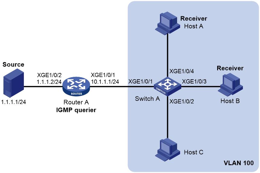
As shown in Figure 4, Router A runs IGMPv2 and acts as the IGMP querier. Switch A runs IGMPv2 snooping.
Configure a multicast group policy and simulated joining to meet the following requirements:
· Host A and Host B receive only the multicast data addressed to multicast group 224.1.1.1. Multicast data can be forwarded through Ten-GigabitEthernet 1/0/3 and Ten-GigabitEthernet 1/0/4 of Switch A uninterruptedly, even though Host A and Host B fail to receive the multicast data.
· Switch A will drop unknown multicast data instead of flooding it in VLAN 100.
Configuration procedure
1. Assign an IP address and subnet mask to each interface, as shown in Figure 4. (Details not shown.)
2. Configure Router A:
# Enable IP multicast routing.
<RouterA> system-view
[RouterA] multicast routing
[RouterA-mrib] quit
# Enable IGMP on Ten-GigabitEthernet 1/0/1.
[RouterA] interface ten-gigabitethernet 1/0/1
[RouterA-Ten-GigabitEthernet1/0/1] igmp enable
[RouterA-Ten-GigabitEthernet1/0/1] quit
# Enable PIM-DM on Ten-GigabitEthernet 1/0/2.
[RouterA] interface ten-gigabitethernet 1/0/2
[RouterA-Ten-GigabitEthernet1/0/2] pim dm
[RouterA-Ten-GigabitEthernet1/0/2] quit
3. Configure Switch A:
# Enable the IGMP snooping feature.
<SwitchA> system-view
[SwitchA] igmp-snooping
[SwitchA-igmp-snooping] quit
# Create VLAN 100, and assign Ten-GigabitEthernet 1/0/1 through Ten-GigabitEthernet 1/0/4 to the VLAN.
[SwitchA] vlan 100
[SwitchA-vlan100] port ten-gigabitethernet 1/0/1 to ten-gigabitethernet 1/0/4
# Enable IGMP snooping, and enable dropping unknown multicast data for VLAN 100.
[SwitchA-vlan100] igmp-snooping enable
[SwitchA-vlan100] igmp-snooping drop-unknown
[SwitchA-vlan100] quit
# Configure a multicast group policy so that hosts in VLAN 100 can join only multicast group 224.1.1.1.
[SwitchA] acl basic 2001
[SwitchA-acl-ipv4-basic-2001] rule permit source 224.1.1.1 0
[SwitchA-acl-ipv4-basic-2001] quit
[SwitchA] igmp-snooping
[SwitchA-igmp-snooping] group-policy 2001 vlan 100
[SwitchA-igmp-snooping] quit
# Configure Ten-GigabitEthernet 1/0/3 and Ten-GigabitEthernet 1/0/4 as simulated member hosts of multicast group 224.1.1.1.
[SwitchA] interface ten-gigabitethernet 1/0/3
[SwitchA-Ten-GigabitEthernet1/0/3] igmp-snooping host-join 224.1.1.1 vlan 100
[SwitchA-Ten-GigabitEthernet1/0/3] quit
[SwitchA] interface ten-gigabitethernet 1/0/4
[SwitchA-Ten-GigabitEthernet1/0/4] igmp-snooping host-join 224.1.1.1 vlan 100
[SwitchA-Ten-GigabitEthernet1/0/4] quit
Verifying the configuration
# Send IGMP reports from Host A and Host B to join multicast groups 224.1.1.1 and 224.2.2.2. (Details not shown.)
# Display information about dynamic IGMP snooping group entries for VLAN 100 on Switch A.
[SwitchA] display igmp-snooping group vlan 100
Total 1 entries.
VLAN 100: Total 1 entries.
(0.0.0.0, 224.1.1.1)
Host ports (2 in total):
XGE1/0/3 (00:03:23)
XGE1/0/4 (00:04:10)
The output shows the following information:
· Host A and Host B have joined multicast group 224.1.1.1 through the member ports Ten-GigabitEthernet 1/0/4 and Ten-GigabitEthernet 1/0/3 on Switch A, respectively.
· Host A and Host B have failed to join multicast group 224.2.2.2.
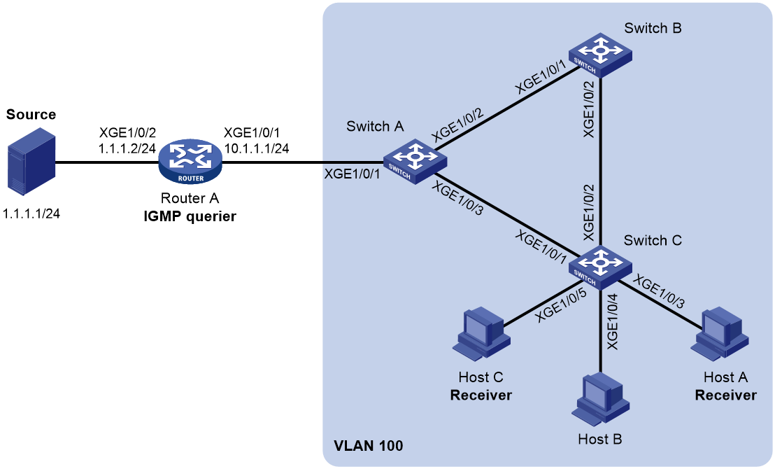
Static port configuration example (for VLANs)
Network requirements
As shown in Figure 5:
· Router A runs IGMPv2 and acts as the IGMP querier. Switch A, Switch B, and Switch C run IGMPv2 snooping.
· Host A and host C are permanent receivers of multicast group 224.1.1.1.
Configure static ports to meet the following requirements:
· To enhance the reliability of multicast traffic transmission, configure Ten-GigabitEthernet 1/0/3 and Ten-GigabitEthernet 1/0/5 on Switch C as static member ports for multicast group 224.1.1.1.
· Suppose the STP runs on the network. To avoid data loops, the forwarding path from Switch A to Switch C is blocked. Multicast data flows to the receivers attached to Switch C only along the path of Switch A—Switch B—Switch C. When this path is blocked, a minimum of one IGMP query-response cycle must be completed before multicast data flows to the receivers along the path of Switch A—Switch C. In this case, the multicast delivery is interrupted during the process. For more information about the STP, see Layer 2—LAN Switching Configuration Guide.
Configure Ten-GigabitEthernet 1/0/3 on Switch A as a static router port. Then, multicast data can flow to the receivers nearly uninterruptedly along the path of Switch A—Switch C when the path of Switch A—Switch B—Switch C is blocked.
Configuration procedure
1. Assign an IP address and subnet mask to each interface, as shown in Figure 5. (Details not shown.)
2. Configure Router A:
# Enable IP multicast routing.
<RouterA> system-view
[RouterA] multicast routing
[RouterA-mrib] quit
# Enable IGMP on Ten-GigabitEthernet 1/0/1.
[RouterA] interface ten-gigabitethernet 1/0/1
[RouterA-Ten-GigabitEthernet1/0/1] igmp enable
[RouterA-Ten-GigabitEthernet1/0/1] quit
# Enable PIM-DM on Ten-GigabitEthernet 1/0/2.
[RouterA] interface ten-gigabitethernet 1/0/2
[RouterA-Ten-GigabitEthernet1/0/2] pim dm
[RouterA-Ten-GigabitEthernet1/0/2] quit
3. Configure Switch A:
# Enable the IGMP snooping feature.
<SwitchA> system-view
[SwitchA] igmp-snooping
[SwitchA-igmp-snooping] quit
# Create VLAN 100, and assign Ten-GigabitEthernet 1/0/1 through Ten-GigabitEthernet 1/0/3 to the VLAN.
[SwitchA] vlan 100
[SwitchA-vlan100] port ten-gigabitethernet 1/0/1 to ten-gigabitethernet 1/0/3
# Enable IGMP snooping for VLAN 100.
[SwitchA-vlan100] igmp-snooping enable
[SwitchA-vlan100] quit
# Configure Ten-GigabitEthernet 1/0/3 as a static router port.
[SwitchA] interface ten-gigabitethernet 1/0/3
[SwitchA-Ten-GigabitEthernet1/0/3] igmp-snooping static-router-port vlan 100
[SwitchA-Ten-GigabitEthernet1/0/3] quit
4. Configure Switch B:
# Enable the IGMP snooping feature.
<SwitchB> system-view
[SwitchB] igmp-snooping
[SwitchB-igmp-snooping] quit
# Create VLAN 100, and assign Ten-GigabitEthernet 1/0/1 and Ten-GigabitEthernet 1/0/2 to the VLAN.
[SwitchB] vlan 100
[SwitchB-vlan100] port ten-gigabitethernet 1/0/1 ten-gigabitethernet 1/0/2
# Enable IGMP snooping for VLAN 100.
[SwitchB-vlan100] igmp-snooping enable
[SwitchB-vlan100] quit
5. Configure Switch C:
# Enable the IGMP snooping feature.
<SwitchC> system-view
[SwitchC] igmp-snooping
[SwitchC-igmp-snooping] quit
# Create VLAN 100, and assign Ten-GigabitEthernet 1/0/1 through Ten-GigabitEthernet 1/0/5 to the VLAN.
[SwitchC] vlan 100
[SwitchC-vlan100] port ten-gigabitethernet 1/0/1 to ten-gigabitethernet 1/0/5
# Enable IGMP snooping for VLAN 100.
[SwitchC-vlan100] igmp-snooping enable
[SwitchC-vlan100] quit
# Configure Ten-GigabitEthernet 1/0/3 and Ten-GigabitEthernet 1/0/5 as static member ports for multicast group 224.1.1.1.
[SwitchC] interface ten-gigabitethernet 1/0/3
[SwitchC-Ten-GigabitEthernet1/0/3] igmp-snooping static-group 224.1.1.1 vlan 100
[SwitchC-Ten-GigabitEthernet1/0/3] quit
[SwitchC] interface ten-gigabitethernet 1/0/5
[SwitchC-Ten-GigabitEthernet1/0/5] igmp-snooping static-group 224.1.1.1 vlan 100
[SwitchC-Ten-GigabitEthernet1/0/5] quit
Verifying the configuration
# Display static router port information for VLAN 100 on Switch A.
[SwitchA] display igmp-snooping static-router-port vlan 100
VLAN 100:
Router ports (1 in total):
XGE1/0/3
The output shows that Ten-GigabitEthernet 1/0/3 on Switch A has become a static router port.
# Display information about static IGMP snooping group entries for VLAN 100 on Switch C.
[SwitchC] display igmp-snooping static-group vlan 100
Total 1 entries.
VLAN 100: Total 1 entries.
(0.0.0.0, 224.1.1.1)
Host ports (2 in total):
XGE1/0/3
XGE1/0/5
The output shows that Ten-GigabitEthernet 1/0/3 and Ten-GigabitEthernet 1/0/5 on Switch C have become static member ports of multicast group 224.1.1.1.
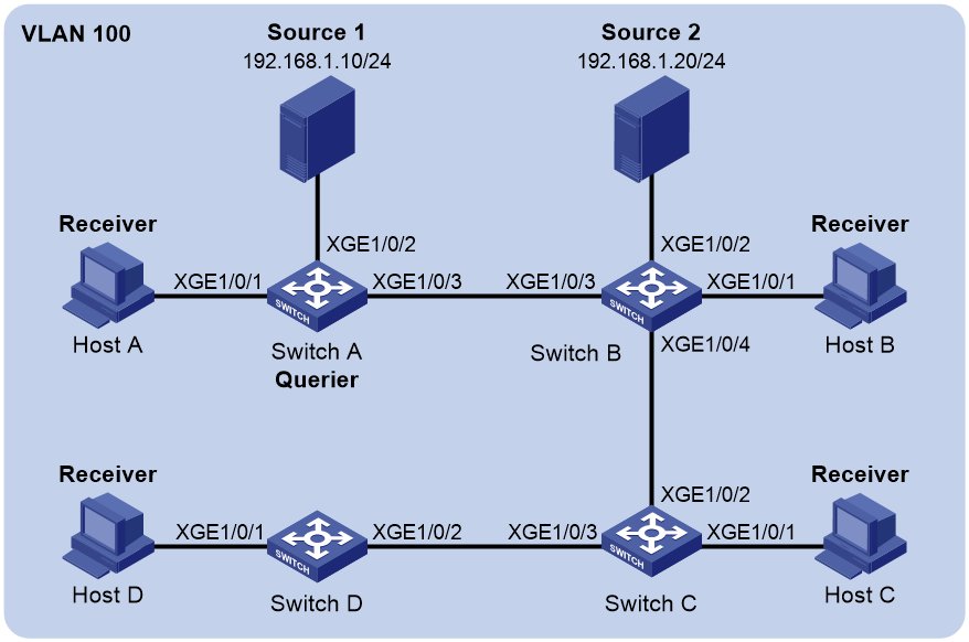
IGMP snooping querier configuration example (for VLANs)
Network requirements
As shown in Figure 6:
· The network is a Layer 2-only network.
· Source 1 and Source 2 send multicast data to multicast groups 224.1.1.1 and 225.1.1.1, respectively.
· Host A and Host C are receivers of multicast group 224.1.1.1, and Host B and Host D are receivers of multicast group 225.1.1.1.
· All host receivers run IGMPv2, and all switches run IGMPv2 snooping. Switch A (which is close to the multicast sources) acts as the IGMP snooping querier.
Configure the switches to meet the following requirements:
· To prevent the switches from flooding unknown data in the VLAN, enable all the switches to drop unknown multicast data.
· A switch does not mark a port that receives an IGMP query with source IP address 0.0.0.0 as a dynamic router port. This adversely affects the establishment of Layer 2 forwarding entries and multicast traffic forwarding. To avoid this, configure the source IP address of IGMP queries as a non-zero IP address.
Configuration procedure
1. Configure Switch A:
# Enable the IGMP snooping feature.
<SwitchA> system-view
[SwitchA] igmp-snooping
[SwitchA-igmp-snooping] quit
# Create VLAN 100, and assign Ten-GigabitEthernet 1/0/1 through Ten-GigabitEthernet 1/0/3 to the VLAN.
[SwitchA] vlan 100
[SwitchA-vlan100] port ten-gigabitethernet 1/0/1 to ten-gigabitethernet 1/0/3
# Enable IGMP snooping, and enable dropping unknown multicast data for VLAN 100.
[SwitchA-vlan100] igmp-snooping enable
[SwitchA-vlan100] igmp-snooping drop-unknown
# Configure Switch A as the IGMP snooping querier.
[SwitchA-vlan100] igmp-snooping querier
[SwitchA-vlan100] quit
# In VLAN 100, specify 192.168.1.1 as the source IP address of IGMP general queries.
[SwitchA-vlan100] igmp-snooping general-query source-ip 192.168.1.1
# In VLAN 100, specify 192.168.1.1 as the source IP address of IGMP group-specific queries.
[SwitchA-vlan100] igmp-snooping special-query source-ip 192.168.1.1
[SwitchA-vlan100] quit
2. Configure Switch B:
# Enable the IGMP snooping feature.
<SwitchB> system-view
[SwitchB] igmp-snooping
[SwitchB-igmp-snooping] quit
# Create VLAN 100, and assign Ten-GigabitEthernet 1/0/1 through Ten-GigabitEthernet 1/0/4 to the VLAN.
[SwitchB] vlan 100
[SwitchB-vlan100] port ten-gigabitethernet 1/0/1 to ten-gigabitethernet 1/0/4
# Enable IGMP snooping, and enable dropping unknown multicast data for VLAN 100.
[SwitchB-vlan100] igmp-snooping enable
[SwitchB-vlan100] igmp-snooping drop-unknown
[SwitchB-vlan100] quit
3. Configure Switch C:
# Enable the IGMP snooping feature.
<SwitchC> system-view
[SwitchC] igmp-snooping
[SwitchC-igmp-snooping] quit
# Create VLAN 100, and assign Ten-GigabitEthernet 1/0/1 through Ten-GigabitEthernet 1/0/3 to the VLAN.
[SwitchC] vlan 100
[SwitchC-vlan100] port ten-gigabitethernet 1/0/1 to ten-gigabitethernet 1/0/3
# Enable IGMP snooping, and enable dropping unknown multicast data for VLAN 100.
[SwitchC-vlan100] igmp-snooping enable
[SwitchC-vlan100] igmp-snooping drop-unknown
[SwitchC-vlan100] quit
4. Configure Switch D:
# Enable the IGMP snooping feature.
<SwitchD> system-view
[SwitchD] igmp-snooping
[SwitchD-igmp-snooping] quit
# Create VLAN 100, and assign Ten-GigabitEthernet 1/0/1 and Ten-GigabitEthernet 1/0/2 to the VLAN.
[SwitchD] vlan 100
[SwitchD-vlan100] port ten-gigabitethernet 1/0/1 to ten-gigabitethernet 1/0/2
# Enable IGMP snooping, and enable dropping unknown multicast data for VLAN 100.
[SwitchD-vlan100] igmp-snooping enable
[SwitchD-vlan100] igmp-snooping drop-unknown
[SwitchD-vlan100] quit
Verifying the configuration
# Display statistics for IGMP messages and PIMv2 hello messages learned through IGMP snooping on Switch B.
[SwitchB] display igmp-snooping statistics
Received IGMP general queries: 3
Received IGMPv1 reports: 0
Received IGMPv2 reports: 12
Received IGMP leaves: 0
Received IGMPv2 specific queries: 0
Sent IGMPv2 specific queries: 0
Received IGMPv3 reports: 0
Received IGMPv3 reports with right and wrong records: 0
Received IGMPv3 specific queries: 0
Received IGMPv3 specific sg queries: 0
Sent IGMPv3 specific queries: 0
Sent IGMPv3 specific sg queries: 0
Received PIMv2 hello: 0
Received error IGMP messages: 0
The output shows that all switches except Switch A can receive the IGMP general queries after Switch A acts as the IGMP snooping querier.
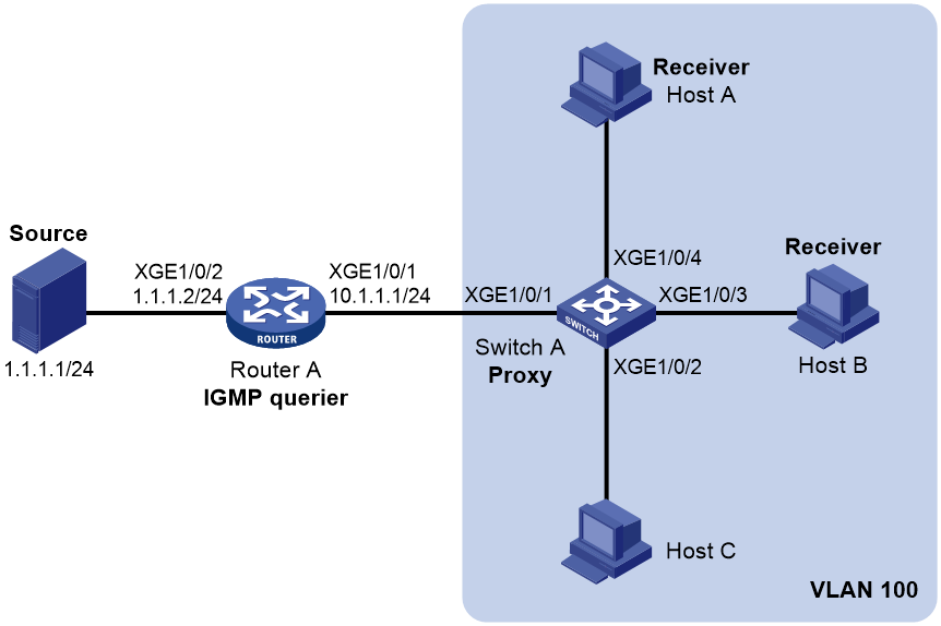
IGMP snooping proxying configuration example (for VLANs)
Network requirements
As shown in Figure 7, Router A runs IGMPv2 and acts as the IGMP querier. Switch A runs IGMPv2 snooping. Configure IGMP snooping proxying so that Switch A can perform the following actions:
· Forward IGMP report and leave messages to Router A.
· Respond to IGMP queries sent by Router A and forward the queries to downstream hosts.
Configuration procedure
1. Assign an IP address and subnet mask to each interface, as shown in Figure 7. (Details not shown.)
2. Configure Router A:
# Enable IP multicast routing.
<RouterA> system-view
[RouterA] multicast routing
[RouterA-mrib] quit
# Enable IGMP and PIM-DM on Ten-GigabitEthernet 1/0/1.
[RouterA] interface ten-gigabitethernet 1/0/1
[RouterA-Ten-GigabitEthernet1/0/1] igmp enable
[RouterA-Ten-GigabitEthernet1/0/1] pim dm
[RouterA-Ten-GigabitEthernet1/0/1] quit
# Enable PIM-DM on Ten-GigabitEthernet 1/0/2.
[RouterA] interface ten-gigabitethernet 1/0/2
[RouterA-Ten-GigabitEthernet1/0/2] pim dm
[RouterA-Ten-GigabitEthernet1/0/2] quit
3. Configure Switch A:
# Enable the IGMP snooping feature.
<SwitchA> system-view
[SwitchA] igmp-snooping
[SwitchA-igmp-snooping] quit
# Create VLAN 100, and assign Ten-GigabitEthernet 1/0/1 through Ten-GigabitEthernet 1/0/4 to the VLAN.
[SwitchA] vlan 100
[SwitchA-vlan100] port ten-gigabitethernet 1/0/1 to ten-gigabitethernet 1/0/4
# Enable IGMP snooping and IGMP snooping proxying for VLAN 100.
[SwitchA-vlan100] igmp-snooping enable
[SwitchA-vlan100] igmp-snooping proxy enable
[SwitchA-vlan100] quit
Verifying the configuration
# Send an IGMP report to join multicast group 224.1.1.1 from Host A and Host B. (Details not shown.)
# Display information about dynamic IGMP snooping group entries on Switch A.
[SwitchA] display igmp-snooping group
Total 1 entries.
VLAN 100: Total 1 entries.
(0.0.0.0, 224.1.1.1)
Host ports (2 in total):
XGE1/0/3 (00:04:00)
XGE1/0/4 (00:04:04)
The output shows that Ten-GigabitEthernet1/0/1 and Ten-GigabitEthernet1/0/1 are member ports of multicast group 224.1.1.1. Both Host A and Host B will receive multicast data for the group
# Display information about IGMP group entries on Router A.
[RouterA] display igmp group
IGMP groups in total: 1
Ten-GigabitEthernet1/0/1(10.1.1.1):
IGMP groups reported in total: 1
Group address Last reporter Uptime Expires
224.1.1.1 0.0.0.0 00:00:31 00:02:03
# Send an IGMP leave message to leave multicast group (224.1.1.1) from Host A. (Details not shown.)
# Display IGMP snooping group membership information on Switch A.
[SwitchA] display igmp-snooping group
Total 1 entries.
VLAN 100: Total 1 entries.
(0.0.0.0, 224.1.1.1)
Host ports (1 in total):
XGE1/0/3 ( 00:01:23 )
The output shows that Ten-GigabitEthernet 1/0/4 (connected to Host A) has been deleted from the entry of multicast group (224.1.1.1).
IGMP snooping configuration example (for VSIs)
Network requirements
As shown in Figure 8:
· There are three sites in VPN a. They are connected through the VPLS network.
· In VLAN 100, Source in Site 1, Host A in Site 2, and Host B in Site 3 communicate with CE 1, CE 2, and CE 3, respectively.
Configure the devices so that Host A and Host B can receive multicast data from Source.
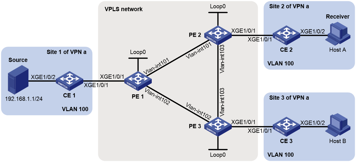
Table 1 Interface and IP address assignment
|
Device |
Interface |
IP address |
Device |
Interface |
IP address |
|
PE 1 |
Vlan-int101 |
10.110.1.1/24 |
PE 2 |
Loop0 |
2.2.2.2/32 |
|
PE 1 |
Vlan-int102 |
10.110.2.1/24 |
PE 3 |
Loop0 |
10.110.2.2/24 |
|
PE 1 |
Loop0 |
1.1.1.1/32 |
PE 3 |
Loop0 |
10.110.3.2/24 |
|
PE 2 |
Vlan-int101 |
10.110.1.2/24 |
PE 3 |
Loop0 |
3.3.3.3/32 |
|
PE 2 |
Vlan-int103 |
10.110.3.1/24 |
|
|
|
Configuration procedure
1. Assign an IP address and subnet mask to each interface on the VPLS network, as shown in Table 1. (Details not shown.)
2. Configure OSPF on the switches on the VPLS network. (Details not shown.)
3. Configure CE 1:
# Enable the IGMP snooping feature.
<CE1> system-view
[CE1] igmp-snooping
[CE1-igmp-snooping] quit
# Create VLAN 100, and assign Ten-GigabitEthernet 1/0/2 to VLAN 100.
[CE1] vlan 100
[CE1-vlan100] port ten-gigabitethernet 1/0/2
# In VLAN 100, enable IGMP snooping, and enable dropping unknown multicast data.
[CE1-vlan100] igmp-snooping enable
[CE1-vlan100] igmp-snooping drop-unknown
# Configure Ten-GigabitEthernet 1/0/1 as a trunk port, and assign it to VLAN 100.
[CE1] interface ten-gigabitethernet 1/0/1
[CE1-Ten-GigabitEthernet1/0/1] port link-type trunk
[CE1-Ten-GigabitEthernet1/0/1] port trunk permit vlan 100
[CE1-Ten-GigabitEthernet1/0/1] quit
# In VLAN 100, enable the IGMP snooping querier.
[CE1-vlan100] igmp-snooping querier
# In VLAN 100, specify 192.168.1.100 as the source IP address of IGMP general queries and IGMP group-specific queries.
[CE1-vlan100] igmp-snooping general-query source-ip 192.168.1.100
[CE1-vlan100] igmp-snooping special-query source-ip 192.168.1.100
4. Configure CE 2:
# Enable the IGMP snooping feature.
<CE2> system-view
[CE2] igmp-snooping
[CE2-igmp-snooping] quit
# Create VLAN 100, and assign Ten-GigabitEthernet 1/0/2 to VLAN100.
[CE2] vlan 100
[CE2-vlan100] port ten-gigabitethernet 1/0/2
# In VLAN 100, enable IGMP snooping, and enable dropping unknown multicast data.
[CE2-vlan100] igmp-snooping enable
[CE2-vlan100] igmp-snooping drop-unknown
# Configure Ten-GigabitEthernet 1/0/1 as a trunk port, and assign it to VLAN 100.
[CE2] interface ten-gigabitethernet 1/0/1
[CE2-Ten-GigabitEthernet1/0/1] port link-type trunk
[CE2-Ten-GigabitEthernet1/0/1] port trunk permit vlan 100
[CE2-Ten-GigabitEthernet1/0/1] quit
5. Configure CE 3:
# Enable the IGMP snooping feature.
<CE3> system-view
[CE3] igmp-snooping
[CE3-igmp-snooping] quit
# Create VLAN 100, and assign Ten-GigabitEthernet 1/0/2 to VLAN100.
[CE3] vlan 100
[CE3-vlan100] port ten-gigabitethernet 1/0/2
# In VLAN 100, enable IGMP snooping, and dropping unknown multicast data.
[CE3-vlan100] igmp-snooping enable
[CE3-vlan100] igmp-snooping drop-unknown
# Configure Ten-GigabitEthernet 1/0/1 as a trunk port, and assign it to VLAN 100.
[CE3] interface ten-gigabitethernet 1/0/1
[CE3-Ten-GigabitEthernet1/0/1] port link-type trunk
[CE3-Ten-GigabitEthernet1/0/1] port trunk permit vlan 100
[CE3-Ten-GigabitEthernet1/0/1] quit
6. Configure PE 1:
# Configure the LSR ID as 1.1.1.1 for the local node, and enable L2VPN and LDP.
<PE1> system-view
[PE1] mpls lsr-id 1.1.1.1
[PE1] l2vpn enable
[PE1] mpls ldp
[PE1-ldp] quit
# Enable MPLS and LDP on VLAN-interface 101.
[PE1] interface vlan-interface 101
[PE1-Vlan-interface101] mpls enable
[PE1-Vlan-interface101] mpls ldp enable
[PE1-Vlan-interface101] quit
# Enable MPLS and LDP on VLAN-interface 102.
[PE1] interface vlan-interface 102
[PE1-Vlan-interface102] mpls enable
[PE1-Vlan-interface102] mpls ldp enable
[PE1-Vlan-interface102] quit
# Create a VSI named aaa, and specify the VSI to establish PWs statically.
[PE1] vsi aaa
[PE1-vsi-aaa] pwsignaling static
# Configure PWs for VSI aaa.
[PE1-vsi-aaa-static] peer 2.2.2.2 pw-id 3 in-label 100 out-label 100
[PE1-vsi-aaa-static-2.2.2.2-3] quit
[PE1-vsi-aaa-static] peer 3.3.3.3 pw-id 3 in-label 200 out-label 200
[PE1-vsi-aaa-static-3.3.3.3-3] quit
[PE1-vsi-aaa-static] quit
[PE1-vsi-aaa] quit
# Bind Ten-GigabitEthernet 1/0/1 to VSI aaa.
[PE1] interface ten-gigabitethernet 1/0/1
[PE1-Ten-GigabitEthernet1/0/1] service-instance 1
[PE1-Ten-GigabitEthernet1/0/1-srv1] encapsulation s-vid 5
[PE1-Ten-GigabitEthernet1/0/1-srv1] xconnect vsi aaa
[PE1-Ten-GigabitEthernet1/0/1-srv1] quit
[PE1-Ten-GigabitEthernet1/0/1] quit
# Enable the IGMP snooping feature.
[PE1] igmp-snooping
[PE1-igmp-snooping] quit
# Enable IGMP snooping, and enable dropping unknown multicast data for VSI aaa.
[PE1] vsi aaa
[PE1-vsi-aaa] igmp-snooping enable
[PE1-vsi-aaa] igmp-snooping drop-unknown
[PE1-vsi-aaa] quit
7. Configure PE 2:
# Configure the LSR ID as 2.2.2.2 for the local node, and enable L2VPN and LDP.
<PE2> system-view
[PE2] mpls lsr-id 2.2.2.2
[PE2] l2vpn enable
[PE2] mpls ldp
[PE2-ldp] quit
# Enable MPLS and LDP on VLAN-interface 101.
[PE2] interface vlan-interface 101
[PE2-Vlan-interface101] mpls enable
[PE2-Vlan-interface101] mpls ldp enable
[PE2-Vlan-interface101] quit
# Enable MPLS and LDP on VLAN-interface 103.
[PE2] interface vlan-interface 103
[PE2-Vlan-interface103] mpls enable
[PE2-Vlan-interface103] mpls ldp enable
[PE2-Vlan-interface103] quit
# Create a VSI named aaa, and specify the VSI to establish PWs statically.
[PE2] vsi aaa
[PE2-vsi-aaa] pwsignaling static
# Configure PWs for VSI aaa.
[PE2-vsi-aaa-static] peer 1.1.1.1 pw-id 3 in-label 100 out-label 100
[PE2-vsi-aaa-static-1.1.1.1-3] quit
[PE2-vsi-aaa-static] peer 3.3.3.3 pw-id 3 in-label 300 out-label 300
[PE2-vsi-aaa-static-3.3.3.3-3] quit
[PE2-vsi-aaa-static] quit
[PE2-vsi-aaa] quit
# Bind Ten-GigabitEthernet 1/0/1 to VSI aaa.
[PE2] interface ten-gigabitethernet 1/0/1
[PE2-Ten-GigabitEthernet1/0/1] service-instance 1
[PE2-Ten-GigabitEthernet1/0/1-srv1] encapsulation s-vid 5
[PE2-Ten-GigabitEthernet1/0/1-srv1] xconnect vsi aaa
[PE2-Ten-GigabitEthernet1/0/1-srv1] quit
[PE2-Ten-GigabitEthernet1/0/1] quit
# Enable the IGMP snooping feature.
[PE2] igmp-snooping
[PE2-igmp-snooping] quit
# In VSI aaa, enable IGMP snooping, and enable dropping unknown multicast data.
[PE2] vsi aaa
[PE2-vsi-aaa] igmp-snooping enable
[PE2-vsi-aaa] igmp-snooping drop-unknown
[PE2-vsi-aaa] quit
8. Configure PE 3:
# Configure the LSR ID as 3.3.3.3 for the local node, and enable L2VPN and LDP.
<PE3> system-view
[PE3] mpls lsr-id 3.3.3.3
[PE3] l2vpn enable
[PE3] mpls ldp
[PE3-ldp] quit
# Enable MPLS and LDP on VLAN-interface 102.
[PE3] interface vlan-interface 102
[PE3-Vlan-interface102] mpls enable
[PE3-Vlan-interface102] mpls ldp enable
[PE3-Vlan-interface102] quit
# Enable MPLS and LDP on VLAN-interface 103.
[PE3] interface vlan-interface 103
[PE3-Vlan-interface103] mpls enable
[PE3-Vlan-interface103] mpls ldp enable
[PE3-Vlan-interface103] quit
# Create a VSI named aaa, and specify the VSI to establish PWs statically.
[PE3] vsi aaa
[PE3-vsi-aaa] pwsignaling static
# Configure PWs for VSI aaa.
[PE3-vsi-aaa-static] peer 1.1.1.1 pw-id 3 in-label 200 out-label 200
[PE3-vsi-aaa-static-1.1.1.1-3] quit
[PE3-vsi-aaa-static] peer 2.2.2.2 pw-id 3 in-label 300 out-label 300
[PE3-vsi-aaa-static-2.2.2.2-3] quit
[PE3-vsi-aaa-static] quit
[PE3-vsi-aaa] quit
# Bind Ten-GigabitEthernet 1/0/1 to VSI aaa.
[PE3] interface ten-gigabitethernet 1/0/1
[PE3-Ten-GigabitEthernet1/0/1] service-instance 1
[PE3-Ten-GigabitEthernet1/0/1-srv1] encapsulation s-vid 5
[PE3-Ten-GigabitEthernet1/0/1-srv1] xconnect vsi aaa
[PE3-Ten-GigabitEthernet1/0/1-srv1] quit
[PE3-Ten-GigabitEthernet1/0/1] quit
# Enable the IGMP snooping feature.
[PE3] igmp-snooping
[PE3-igmp-snooping] quit
# In VSI aaa, enable IGMP snooping, and enable dropping unknown multicast data.
[PE3] vsi aaa
[PE3-vsi-aaa] igmp-snooping enable
[PE3-vsi-aaa] igmp-snooping drop-unknown
[PE3-vsi-aaa] quit
Verifying the configuration
# Display detailed information about dynamic IGMP snooping group entries for VSI aaa on PE 1.
[PE1] display igmp-snooping group vsi aaa verbose
Total 1 entries.
VSI aaa: Total 1 entries.
(0.0.0.0, 225.0.0.1)
Attribute: global port
FSM information: normal
Host slots (0 in total):
Host ports (1 in total):
NPW (Link ID 9) (00:02:24)
VLAN pairs (1 in total):
Outer VLAN 100 Inner VLAN 0 (00:02:24)
# Display detailed information about dynamic router ports for VSI aaa on PE 1.
[PE1] display igmp-snooping router-port vsi aaa verbose
VSI aaa:
Router slots (0 in total):
Router ports (1 in total):
XGE1/0/1 (Link ID 0) (00:01:46)
VLAN pairs (1 in total):
Outer VLAN 100 Inner VLAN 0 (00:01:46)
# Display detailed information about dynamic IGMP snooping group entries for VSI aaa on PE 2.
[PE2] display igmp-snooping group vsi aaa verbose
Total 1 entries.
VSI aaa: Total 1 entries.
(0.0.0.0, 225.0.0.1)
Attribute: global port
FSM information: normal
Host slots (0 in total):
Host ports (1 in total):
NPW (Link ID 8) (00:02:07)
VLAN pairs (1 in total):
Outer VLAN 100 Inner VLAN 0 (00:02:07)
# Display detailed information about dynamic router ports for VSI aaa on PE 2.
[PE2] display igmp-snooping router-port vsi aaa verbose
VSI aaa:
Router slots (0 in total):
Router ports (1 in total):
NPW (Link ID 9) (00:01:26)
VLAN pairs (1 in total):
Outer VLAN 100 Inner VLAN 0 00:01:26)
# Display detailed information about dynamic IGMP snooping group entries for VSI aaa on PE 3.
[PE3] display igmp-snooping group vsi aaa verbose
Total 1 entries.
VSI aaa: Total 1 entries.
(0.0.0.0, 225.0.0.1)
Attribute: global port
FSM information: normal
Host slots (0 in total):
Host ports (1 in total):
XGE1/0/1 (Link ID 0) (00:02:04)
VLAN pairs (1 in total):
Outer VLAN 100 Inner VLAN 0 (00:02:04)
# Display detailed information about dynamic router ports for VSI aaa on PE 3.
[PE3] display igmp-snooping router-port vsi aaa verbose
VSI aaa:
Router slots (0 in total):
Router ports (1 in total):
NPW (Link ID 9) (00:01:24)
VLAN pairs (1 in total):
Outer VLAN 100 Inner VLAN 0 (00:01:24)
IGMP snooping configuration example (for VXLANs)
Network requirements
As shown in Figure 9:
· VXLAN 10 provides Layer 2 connectivity for VM 1, VM 2, and VM 3 across the network sites.
· VXLAN 10 uses the unicast mode for flood traffic.
Configure IGMP snooping on the switches to implement Layer 2 multicast forwarding and reduce the burden of replicating known multicast traffic for VTEPs in VXLAN 10.
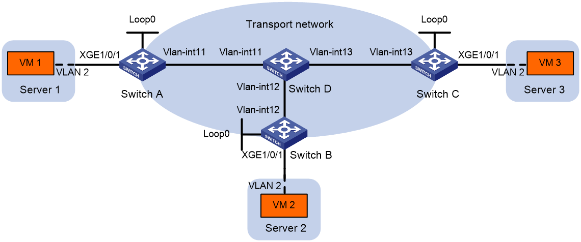
Table 2 Interface and IP address assignment
|
Device |
Interface |
IP address |
Device |
Interface |
IP address |
|
Switch A |
Vlan-int11 |
11.1.1.1/24 |
Switch C |
Vlan-int13 |
13.1.1.3/24 |
|
Switch A |
Loop0 |
1.1.1.1/32 |
Switch C |
Loop0 |
3.3.3.3/32 |
|
Switch B |
Vlan-int12 |
12.1.1.2/24 |
Switch D |
Vlan-int11 |
11.1.1.4/24 |
|
Switch B |
Loop0 |
2.2.2.2/32 |
Switch D |
Vlan-int12 |
12.1.1.4/24 |
|
|
|
|
Switch D |
Vlan-int13 |
13.1.1.4/24 |
Configuration procedure
1. Assign an IP address and subnet mask to each interface on the transport network, as shown in Table 2. (Details not shown.)
2. Configure OSPF on all the switches in the transport network. (Details not shown.)
3. Configure Switch A:
# Enable L2VPN.
<SwitchA> system-view
[SwitchA] l2vpn enable
# Enable Layer 2 forwarding for VXLANs.
[SwitchA] undo vxlan ip-forwarding
# Create a VSI named vpna, and create VXLAN 10.
[SwitchA] vsi vpna
[SwitchA-vsi-vpna] vxlan 10
[SwitchA-vsi-vpna-vxlan-10] quit
[SwitchA-vsi-vpna] quit
# Enable the IGMP snooping feature.
[SwitchA] igmp-snooping
[SwitchA -igmp-snooping] quit
# Enable IGMP snooping and dropping unknown multicast data packets for VSI vpna.
[SwitchA] vsi vpna
[SwitchA-vsi-vpna] igmp-snooping enable
[SwitchA-vsi-vpna] igmp-snooping drop-unknown
[SwitchA-vsi-vpna] quit
# Assign an IP address to Loopback 0. This IP address will be used as the source address of the VXLAN tunnels to Switch B and Switch C.
[SwitchA] interface loopback 0
[SwitchA-Loopback0] ip address 1.1.1.1 255.255.255.255
[SwitchA-Loopback0] quit
# Create a VXLAN tunnel to Switch B.
¡ The tunnel interface name is Tunnel 1.
¡ The source address and destination address of the tunnel interface are 1.1.1.1 and 2.2.2.2, respectively.
[SwitchA] interface tunnel 1 mode vxlan
[SwitchA-Tunnel1] source 1.1.1.1
[SwitchA-Tunnel1] destination 2.2.2.2
[SwitchA-Tunnel1] quit
# Create a VXLAN tunnel to Switch C.
¡ The tunnel interface name is Tunnel 2.
¡ The source address and destination address of the tunnel interface are 1.1.1.1 and 3.3.3.3, respectively.
[SwitchA] interface tunnel 2 mode vxlan
[SwitchA-Tunnel2] source 1.1.1.1
[SwitchA-Tunnel2] destination 3.3.3.3
[SwitchA-Tunnel2] quit
# Assign Tunnel 1 and Tunnel 2 to VXLAN 10.
[SwitchA] vsi vpna
[SwitchA-vsi-vpna] vxlan 10
[SwitchA-vsi-vpna-vxlan-10] tunnel 1
[SwitchA-vsi-vpna-vxlan-10] tunnel 2
[SwitchA-vsi-vpna-vxlan-10] quit
[SwitchA-vsi-vpna] quit
# On Ten-GigabitEthernet 1/0/1, create Ethernet service instance 1000 to match VLAN 2.
[SwitchA] interface ten-gigabitethernet 1/0/1
[SwitchA-Ten-GigabitEthernet1/0/1] service-instance 1000
[SwitchA-Ten-GigabitEthernet1/0/1-srv1000] encapsulation s-vid 2
# Map Ethernet service instance 1000 to VSI vpna.
[SwitchA-Ten-GigabitEthernet1/0/1-srv1000] xconnect vsi vpna
[SwitchA-Ten-GigabitEthernet1/0/1-srv1000] quit
[SwitchA-Ten-GigabitEthernet1/0/1] quit
4. Configure Switch B:
# Enable L2VPN.
<SwitchB> system-view
[SwitchB] l2vpn enable
# Enable Layer 2 forwarding for VXLANs.
[SwitchB] undo vxlan ip-forwarding
# Create a VSI named vpna, and create VXLAN 10.
[SwitchB] vsi vpna
[SwitchB-vsi-vpna] vxlan 10
[SwitchB-vsi-vpna-vxlan-10] quit
[SwitchB-vsi-vpna] quit
# Enable the IGMP snooping feature.
[SwitchB] igmp-snooping
[SwitchB -igmp-snooping] quit
# Enable IGMP snooping and dropping unknown multicast data packets for VSI vpna.
[SwitchB] vsi vpna
[SwitchB-vsi-vpna] igmp-snooping enable
[SwitchB-vsi-vpna] igmp-snooping drop-unknown
[SwitchB-vsi-vpna] quit
# Assign an IP address to Loopback 0. This IP address will be used as the source address of the VXLAN tunnels to Switch A and Switch C.
[SwitchB] interface loopback 0
[SwitchB-Loopback0] ip address 2.2.2.2 255.255.255.255
[SwitchB-Loopback0] quit
# Create a VXLAN tunnel to Switch A.
¡ The tunnel interface name is Tunnel 2.
¡ The source address and destination address of the tunnel interface are 2.2.2.2 and 1.1.1.1, respectively.
[SwitchB] interface tunnel 2 mode vxlan
[SwitchB-Tunnel2] source 2.2.2.2
[SwitchB-Tunnel2] destination 1.1.1.1
[SwitchB-Tunnel2] quit
# Create a VXLAN tunnel to Switch C.
¡ The tunnel interface name is Tunnel 3.
¡ The source address and destination address of the tunnel interface are 2.2.2.2 and 3.3.3.3, respectively.
[SwitchB] interface tunnel 3 mode vxlan
[SwitchB-Tunnel3] source 2.2.2.2
[SwitchB-Tunnel3] destination 3.3.3.3
[SwitchB-Tunnel3] quit
# Assign Tunnel 2 and Tunnel 3 to VXLAN 10.
[SwitchB] vsi vpna
[SwitchB-vsi-vpna] vxlan 10
[SwitchB-vsi-vpna-vxlan-10] tunnel 2
[SwitchB-vsi-vpna-vxlan-10] tunnel 3
[SwitchB-vsi-vpna-vxlan-10] quit
[SwitchB-vsi-vpna] quit
# On Ten-GigabitEthernet 1/0/1, create Ethernet service instance 1000 to match VLAN 2.
[SwitchB] interface ten-gigabitethernet 1/0/1
[SwitchB-Ten-GigabitEthernet1/0/1] service-instance 1000
[SwitchB-Ten-GigabitEthernet1/0/1-srv1000] encapsulation s-vid 2
# Map Ethernet service instance 1000 to VSI vpna.
[SwitchB-Ten-GigabitEthernet1/0/1-srv1000] xconnect vsi vpna
[SwitchB-Ten-GigabitEthernet1/0/1-srv1000] quit
[SwitchB-Ten-GigabitEthernet1/0/1] quit
5. Configure Switch C:
# Enable L2VPN.
<SwitchC> system-view
[SwitchC] l2vpn enable
# Enable Layer 2 forwarding for VXLANs.
[SwitchC] undo vxlan ip-forwarding
# Create a VSI named vpna, and create VXLAN 10.
[SwitchC] vsi vpna
[SwitchC-vsi-vpna] vxlan 10
[SwitchC-vsi-vpna-vxlan-10] quit
[SwitchC-vsi-vpna] quit
# Enable the IGMP snooping feature.
[SwitchB] igmp-snooping
[SwitchB -igmp-snooping] quit
# Enable IGMP snooping for VSI vpna.
[SwitchC] vsi vpna
[SwitchC-vsi-vpna] igmp-snooping enable
# Enable dropping unknown multicast data packets for VSI vpna.
[SwitchC-vsi-vpna] igmp-snooping drop-unknown
# Specify 3.3.3.3 as the source IP address of IGMP general queries in VSI vpna.
[SwitchC-vsi-vpna] igmp-snooping general-query source-ip 3.3.3.3
# Enable the IGMP snooping querier.
[SwitchC-vsi-vpna] igmp-snooping querier
[SwitchC-vsi-vpna] quit
# Assign an IP address to Loopback 0. This address will be used as the source address of the VXLAN tunnels to Switch A and Switch B.
[SwitchC] interface loopback 0
[SwitchC-Loopback0] ip address 3.3.3.3 255.255.255.255
[SwitchC-Loopback0] quit
# Create a VXLAN tunnel to Switch A.
¡ The tunnel interface name is Tunnel 1.
¡ The source address and destination address of the tunnel interface are 3.3.3.3 and 1.1.1.1, respectively.
[SwitchC] interface tunnel 1 mode vxlan
[SwitchC-Tunnel1] source 3.3.3.3
[SwitchC-Tunnel1] destination 1.1.1.1
[SwitchC-Tunnel1] quit
# Create a VXLAN tunnel to Switch B.
¡ The tunnel interface name is Tunnel 3.
¡ The source address and destination address of the tunnel interface are 3.3.3.3 and 2.2.2.2, respectively.
[SwitchC] interface tunnel 3 mode vxlan
[SwitchC-Tunnel3] source 3.3.3.3
[SwitchC-Tunnel3] destination 2.2.2.2
[SwitchC-Tunnel3] quit
# Assign Tunnel 1 and Tunnel 3 to VSI vpna.
[SwitchC] vsi vpna
[SwitchC-vsi-vpna] vxlan 10
[SwitchC-vsi-vpna-vxlan-10] tunnel 1
[SwitchC-vsi-vpna-vxlan-10] tunnel 3
[SwitchC-vsi-vpna-vxlan-10] quit
[SwitchC-vsi-vpna] quit
# On Ten-GigabitEthernet 1/0/1, create Ethernet service instance 1000 to match VLAN 2.
[SwitchC] interface ten-gigabitethernet 1/0/1
[SwitchC-Ten-GigabitEthernet1/0/1] service-instance 1000
[SwitchC-Ten-GigabitEthernet1/0/1-srv1000] encapsulation s-vid 2
# Map Ethernet service instance 1000 to VSI vpna.
[SwitchC-Ten-GigabitEthernet1/0/1-srv1000] xconnect vsi vpna
[SwitchC-Ten-GigabitEthernet1/0/1-srv1000] quit
[SwitchC-Ten-GigabitEthernet1/0/1] quit
Verifying the configuration
# Display dynamic router port information for VSI vpna on Switch A.
[SwitchA] display igmp-snooping router-port vsi vpna
VSI vpna:
Router ports (1 in total):
Tun2 (VXLAN ID 10) (00:04:17)
# Display dynamic router port information for VSI vpna on Switch B.
[SwitchB] display igmp-snooping router-port vsi vpna
VSI vpna:
Router ports (1 in total):
Tun3 (VXLAN ID 10) (00:04:07)
Troubleshooting IGMP snooping
Layer 2 multicast forwarding cannot function
Symptom
Layer 2 multicast forwarding cannot function on the Layer 2 device.
Solution
To resolve the problem:
1. Use the display igmp-snooping command to display IGMP snooping status.
2. If IGMP snooping is not enabled, use the igmp-snooping command in system view to Enable the IGMP snooping feature. Then, use the igmp-snooping enable command in VLAN view or VSI view to enable IGMP snooping for the VLAN or VSI.
3. If IGMP snooping is enabled globally but not enabled for the VLAN or VSI, use the igmp-snooping enable command in VLAN view or VSI view to enable IGMP snooping for the VLAN or VSI.
4. If the problem persists, contact H3C Support.
Multicast group policy does not work
Symptom
Hosts can receive multicast data for multicast groups that are not permitted by the multicast group policy.
Solution
To resolve the problem:
1. Use the display acl command to verify that the configured ACL meets the multicast group policy requirements.
2. Use the display this command in IGMP-snooping view or in a corresponding interface view to verify that the correct multicast group policy has been applied. If the applied policy is not correct, use the group-policy or igmp-snooping group-policy command to apply the correct multicast group policy.
3. Use the display igmp-snooping command to verify that dropping unknown multicast data is enabled. If it is not, use the igmp-snooping drop-unknown command to enable dropping unknown multicast data.
4. If the problem persists, contact H3C Support.
