- Table of Contents
- Related Documents
-
| Title | Size | Download |
|---|---|---|
| 01-Text | 4.36 MB |
Introduction to MPLS VPN Manager
Managing enterprise's MPLS VPN
Using L2VPN Management with non-BGP protocols
Viewing a specific VPN topology
Configuring PEs and the P device
Using L2VPN Management with BGP protocol
Viewing a specific VPN topology
Configuring traffic engineering in MPLS TE Management
Configuring MPLS basic capabilities
Configuring MPLS TE basic capabilities
Configuring an MPLS TE tunnel using static CR-LSP
Configuring an MPLS TE tunnel using dynamic signaling protocol
Getting started with MPLS management
Introduction to MPLS VPN Manager
Multiprotocol Label Switching (MPLS) is a highly scalable networking technology that works with label switching routers (LSR) to create end-to-end circuits for high-speed transmission of virtually any kind of digital data.
To manage MPLS networks and associated equipment, Hewlett Packard Enterprise provides MPLS VPN Manager (MVM), an optional service module that can be added to your H3C Intelligent Management Center (IMC) deployment. MVM includes four applications that provide comprehensive MPLS service management and monitoring, device management, and traffic engineering capabilities from a convenient single platform. The four MVM function modules are:
· MPLS VPN Management.
· L2VPN Management.
· MPLS TE Management.
· MPLS Management.
MPLS VPN Management
MPLS VPN Management (Figure 1) is the base MVM module. With MPLS VPN Management installed and deployed, you can deploy and use the other MVM modules.
Figure 1 MPLS VPN Management Quick Guide page
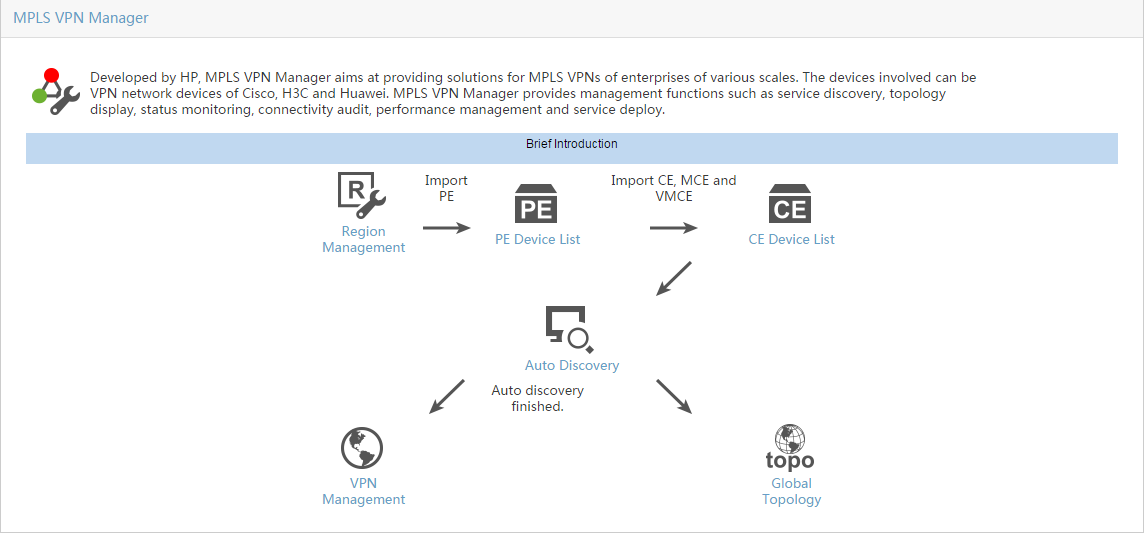
MPLS VPN Management provides scalable and centralized enterprise management tools for VPN network devices from Hewlett Packard Enterprise (H3C), Cisco, and Huawei. These tools include:
· VPN resource management.
· VPN device lists.
· Fault detection.
· Traffic monitoring.
For complete information about MPLS VPN Management, see "Using MPLS VPN Management."
L2VPN Management
The L2VPN Management (Figure 2) provides tools for administering Layer 2 VPN networks, including MPLS-based VPLS networks (using BGP or LDP), MPLS-based VLL networks, and link layer-based provider backbone bridge (PBB) networks. These Layer 2 VPN technologies deliver point-to-point or point-to-multipoint services on wide area networks (WAN). Users can communicate with each other as if they were on the same local area network (LAN).
Figure 2 L2VPN Management Quick Guide page (using non-BGP protocols)
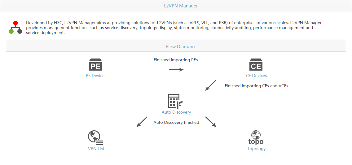
Supporting the VPLS, VLL, and PBB protocols, L2VPN Management enables scalable, multiple-point VPN services. Traditional VPNs provide only the point-to-point services. L2VPN Management provides the following capabilities:
· Importing VPN devices.
· Managing VPN lists and attachment circuits.
· Deploying VPLS, VLL, or PBB VPN (not supported in BGP protocol).
· Discovering devices with VPN that have not been added to L2VPN Management.
· Displaying L2VPN topology.
For complete information about L2VPN Management, see "Using L2VPN Management."
L2VPN Management provides fewer capabilities if you select the BGP protocol during MVM deployment.
MPLS TE Management
Enterprise networks are typically complex, offering a variety of services to network users. Sometimes, network load distribution can become out of balance, causing some network resources to become overloaded while others are underused. The MPLS TE Management (Figure 3) provides traffic engineering tools that enable the administrator to solve network imbalance issues.
Figure 3 MPLS TE Management Quick Guide page
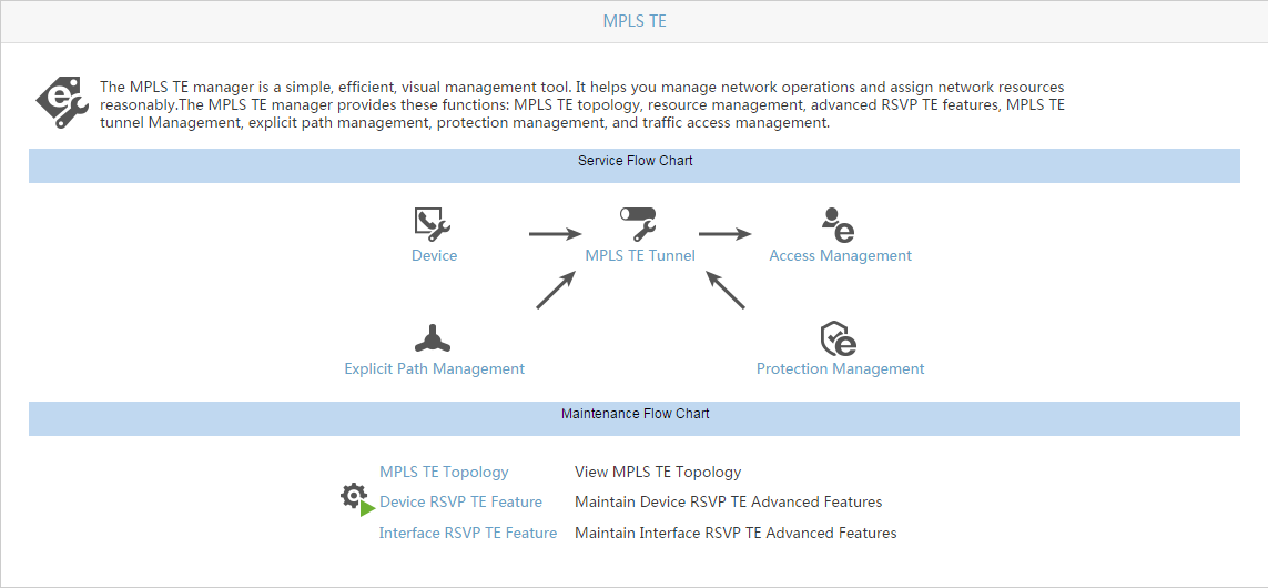
Traffic engineering (TE) is the process of steering traffic across the network backbone to enable efficient use of available bandwidth between two routers. MPLS TE is a technology that enables service providers to more precisely control data transmission paths to avoid network congestion. The MPLS TE Management provides access to a variety of TE tools:
· TE topology.
· Resource management.
· RSVP TE advanced device and interface functionality.
· MPLS TE tunnel management.
· Explicit path management.
· Protection management.
· Traffic access management.
For complete information about MPLS TE Management, see "Using MPLS TE Management."
MPLS Management
The MPLS Management application (Figure 4) provides a comprehensive set of tools that enables administrators to manage and monitor MPLS networks from IMC.
Figure 4 MPLS Management Quick Start page
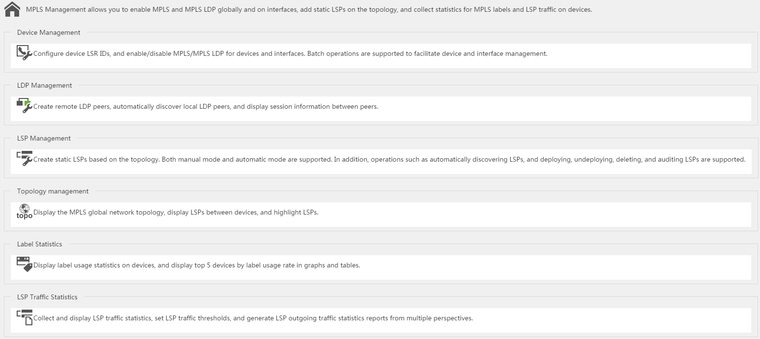
Tools provided by MPLS Management include:
· Device management.
· LDP management.
· LSP management.
· Topology management.
· Label statistics.
· LSP traffic statistics.
For complete information about MPLS Management, see "Using MPLS Management."
Using MPLS VPN Management
Overview
This chapter describes the MPLS L3VPN management features of MPLS VPN Management.
MPLS L3VPN supports various networking modes and has excellent scalability. However, MPLS L3VPN is complicated to deploy and maintain, and only qualified engineers can design and deploy MPLS L3VPN networks. To simplify MPLS L3VPN deployment and maintenance, MVM provides the following functions:
· Automatic discovery of VPNs running on networks—MVM can automatically discover MPLS L3VPNs deployed on a network, and guide network administrators to complete link configuration.
· VPN service deployment wizard—MPLS VPN Management provides a wizard to simplify VPN deployment. For example, you can add an MPLS L3VPN site by following the SA wizard without needing to know the commands and parameters.
· Visualized VPN services—VPN logically isolates services on a physical network. It is difficult to manage services on the VPN network. MPLS VPN Management provides the VPN global topology, access topology, and service topology. These topologies show the physical and logical connections of the whole MPLS VPN network and the connections of each MPLS VPN.
· Visualized VPN traffic—MPLS VPN Management can monitor the inbound and outbound traffic of an MPLS L3VPN or of a site access link (an SA). For an SA, MPLS VPN Management can monitor the bandwidth usage of the inbound and outbound traffic. When the traffic exceeds the threshold, the system generates an alarm. In addition, MPLS VPN Management can cooperate with NTA to allow network administrators to view traffic information on topologies.
· Various VPN audit functions—MPLS VPN Management provides VPN configuration and connectivity audit functions. The configuration audit can display the configuration changes on PE devices. The connectivity audit can display the connectivity status of a VPN and display the positions of faults in a graph.
· Intelligent troubleshooting—MPLS VPN Management can automatically find the faults and causes for broken VPN links.
Basic VPN concepts
Typically, enterprises must find ways to communicate both internally and externally using increasingly complex, and potentially insecure, Internet and LAN technologies. One solution is to use dedicated private lines, which can be expensive, and cannot accommodate mobile offices. A more attractive solution is using a VPN. Using a VPN allows private networks to run on public networks while providing the secure and reliable communication of a private network. VPN uses specific tunneling protocols to transmit VPN packets over different tunnels.
Carriers can make full use of the available network resources to increase services by providing VPN services to enterprises. Enterprises can select different service levels as needed—getting the services they need and reducing their networking cost at the same time. Additionally, the scalability of VPN provides support and convenience for your mobile offices. VPN allows enterprises to connect with remote offices, staff traveling on business, and business partners at a low cost while improving utility of network resources.
VPNs can be classified by:
· Networking model
¡ VPDN—Point-to-point VPN.
¡ Leased line VPN (VPRN, VPLS, VLL).
· Service application
¡ Access VPN—Allows users and small offices to establish private network connections with the intranet or extranet of their enterprise over a public network.
¡ Intranet VPN—Interconnects points distributed inside an enterprise.
¡ Extranet VPN—Extends an enterprise network to co-operators by using VPN.
· Operation mode
¡ CPE-based VPN—IPsec VPN, GRE VPN, and VPDN.
¡ Network-based VPN—Includes VLL, VPRN, VPLS and L3VPN, conducted by ISP. All functions are implemented at network device side.
· Working layer
¡ L2VPN
¡ L3VPN
Quick guide
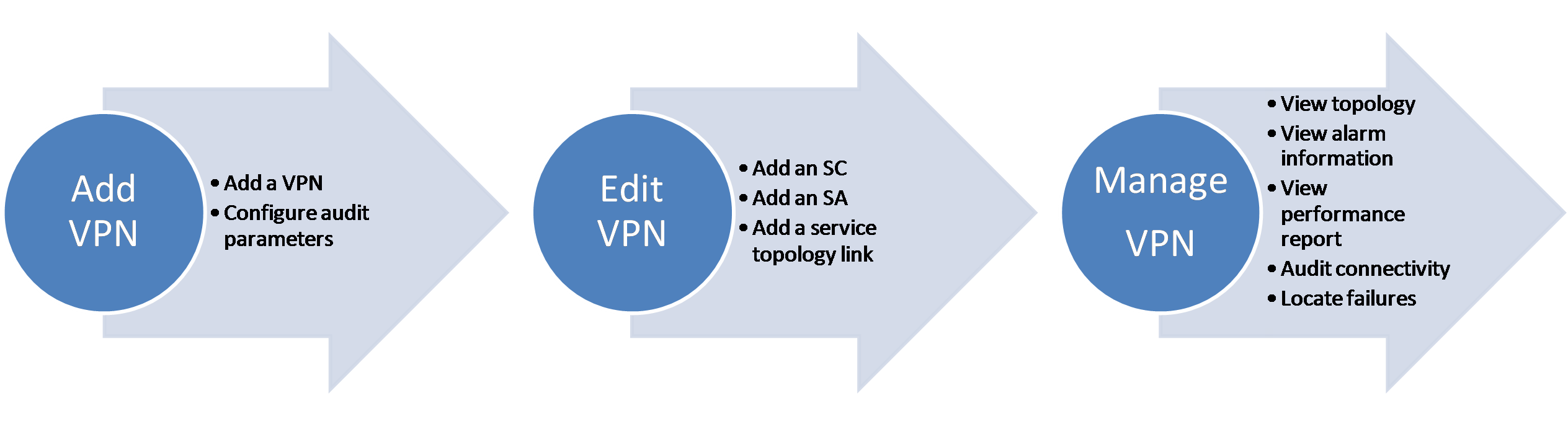
This chapter provides a quick guide that helps you use MPLS VPN Management to add and maintain VPNs.
Figure 5 MPLS VPN Management service flowchart

1. Add regions and devices:
a. (Required.) Add an AS to MPLS VPN Management according to the BGP AS planning on your network or the BGP AS configurations on the P and PE devices. For more information, see "Adding an AS."
b. Add regions.
When an AS is too large to manage, you can divide the AS into multiple regions, and manage P and PE devices by region. Region is a logical concept in MPLS VPN Management. Region configurations are not deployed to devices. For information about how to add a region, see "Adding a region."
c. Enter an AS or enter a region of an AS to import P and PE devices. For more information, see "Importing P devices" and "Importing PE devices."
d. Add CEs to MPLS VPN Management.
- CE—A CE that can be managed by MPLS VPN Management.
- Non-managed CE—A CE from a third-party vendor that MPLS VPN Management cannot manage. MPLS VPN Management creates a virtual CE (VCE) to represent a non-managed CE.
- MCE—A CE that is connected to multiple VPNs. A router that supports the MCE function can serve as an MCE device.
- VMCE—VLAN isolation of MCE, an MCE implemented by a Layer 3 switch that supports multiple VLAN interfaces.
- VMCE—Virtual MCE, an MCE from a third-party vendor that MPLS VPN Management cannot manage.
For more information about CE devices, see "CE device list."
After you complete the previous operations, you can view information about regions, PE devices, and CE devices on the region list, PE device list, and CE device list, respectively.
2. Add VPNs:
After you add regions and devices to MPLS VPN Management, you can add VPNs by using the following methods.
¡ Automatic discovery
Use this method to add existing VPNs on the network to MPLS VPN Management. Select one or more PE devices as seed devices. MPLS VPN Management uses the seed devices to discover the VPNs that have been deployed, and add these VPNs. For more information, see "Auto discovery."
¡ Manual deployment
Use this method to add a new VPN to the network. You can configure the VPN audit period, SC attributes (import RT and export RT), SA links (CE-PE links), and CE-CE links. For more information, see "Adding a VPN" and "Editing VPN details."
After you add VPNs to MVM, you can view and modify VPN information on the VPN list.
3. Maintain VPNs:
MPLS VPN Management provides management functions to maintain VPN services.
¡ Access topology and service topology for each VPN service. The access topology for a VPN displays the CE-PE links in the VPN. The service topology for a VPN displays the logical links between CEs in the VPN. For more information, see "Global topology."
¡ TopN alarms. You can view the top-N VPN services, CE devices, and PE devices by alarm severity. For more information, see "Alarm TopN."
¡ VPN configuration audit and connectivity audit. By using the configuration audit, you can view configuration changes on PE devices. By using the connectivity audit, you can view the connectivity status of a VPN service. For more information, see "VPN management."
¡ Troubleshooting. For disconnected links discovered by connectivity audit, MPLS VPN Management can automatically check configurations, and find the faults and causes. For more information, see "Troubleshooting."
¡ Traffic monitoring. You can monitor the traffic for a VPN and view the traffic monitoring report. For more information, see "Traffic monitor."
VPN resource management
MPLS VPN resource management includes region management, group management, VPN management, SA management, and management VPN, as shown in Figure 6. You can query, view, add, modify, delete, and reuse the resources.
Figure 6 Resource relationships
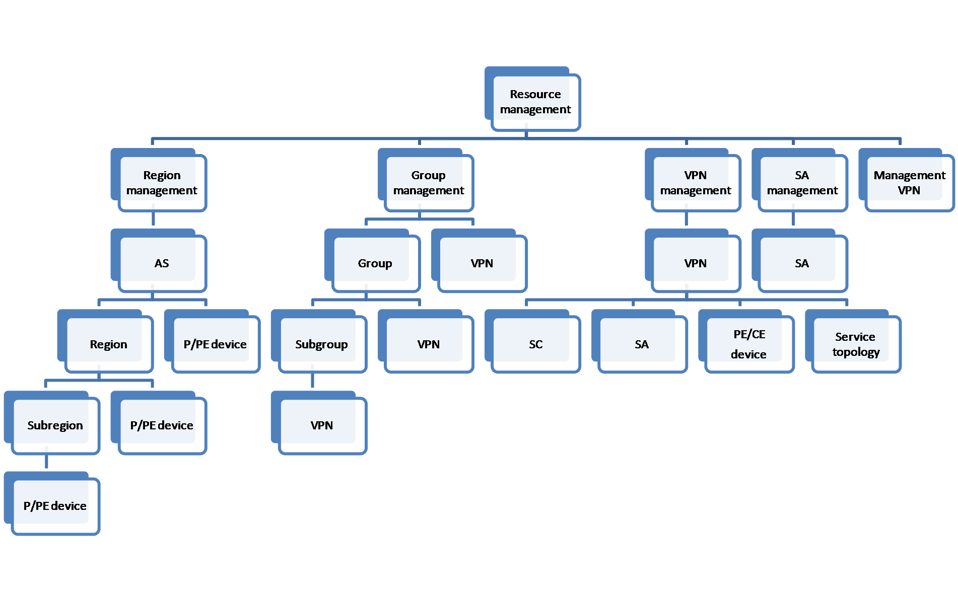
· Region management includes AS, region, P device, and PE device resources. With the region management function, you can add multiple ASs to an MPLS VPN to manage network devices by AS. To further narrow the scope of management, you can add multiple regions to an AS and add multiple subregions to a region according to network devices' locations. After you add the ASs or regions, import the P and PE devices to the ASs or regions.
· Group management includes subgroup and VPN resources. With the group management function, you can group VPNs by department or service. The group-based management improves the efficiency of the VPN service management.
· VPN management manages a single MPLS VPN service, which consists of SC, SA, PE, and CE resources. You can use the VPN management function to add, view, and audit a VPN service. In addition, you can view the access topology and service topology for the VPN service, and configure and modify the VPN information.
· SA management manages the access link between a CE and a PE. You can add, deploy, view, and modify an access link.
· After you add a management VPN to MVM, the system automatically filters traffic of the management VPN so that MVM manages only MPLS VPN services.
VPN resource general view
MPLS VPN Management provides the general view of the statistics for VPN resources, VPN disconnectivity, VPN alarms, and SA deployment.
To display the VPN resource general view page:
1. Click the Service tab.
2. From the navigation tree, select MPLS VPN Manager > VPN Resources.
The VPN Resource General View displays four VPN charts.
Figure 7 VPN resource general view
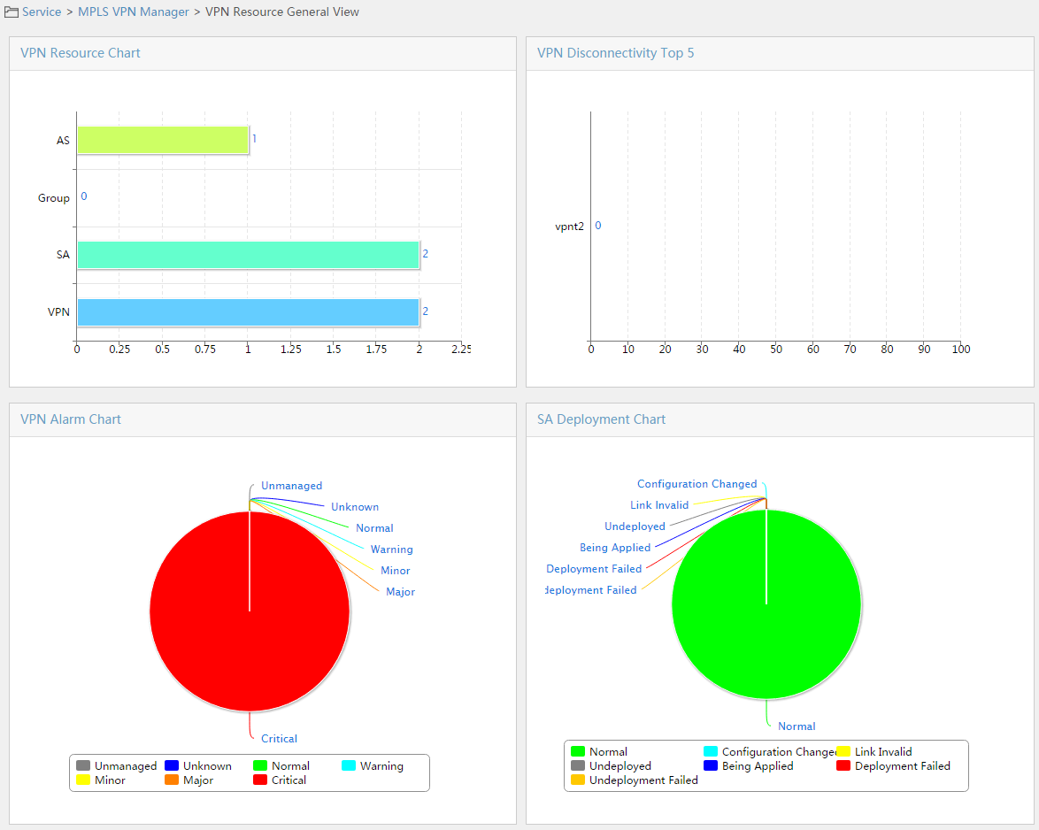
You can obtain the statistics of the existing resource deployment and failures in this page.
· The VPN resource bar chart shows the number of ASs, groups, SAs, and VPNs.
· The VPN disconnectivity Top 5 bar chart shows the top 5 VPN services by disconnectivity.
· The VPN alarm pie chart shows the number and proportion of the VPN services in each alarm state.
· The SA deployment pie chart shows the number of SAs in each deployment state.
Region management
This function manages the ASs and regions in an MPLS VPN. A region supports a maximum of four layers of subregions. After adding ASs and regions, you can import P and PE devices into the ASs, regions, or subregions.
Figure 8 Region management operation process
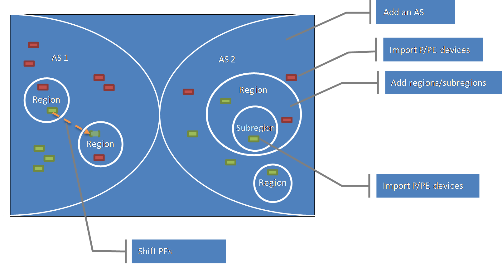
1. Add an AS. For more information, see "Adding an AS."
2. Import P and PE devices to the AS. For more information, see "Importing P devices" and "Importing PE devices."
3. Add regions to a large-scale AS or add subregions to a region. For more information, see "Adding a region."
4. Import P and PE devices to the corresponding regions or subregions. For more information, see "Importing P devices" and "Importing PE devices."
5. When the location of a device changes, use the switch PEs between regions function to switch PEs between regions. For more information, see "Switching PEs between regions."
After you create ASs and regions/subregions, and import P and PE devices, you can synchronize or delete devices in the sub-region/PE list.
Viewing the AS list
1. Click the Service tab.
2. From the navigation tree, select MPLS VPN Manager > VPN Resources > Region management.
The AS List page displays all ASs.
¡ AS Name—Name of the AS. Click the name of the AS to view its details.
¡ AS Number—Number of the AS.
¡ Operation—Provides
the Modify icon ![]() to modify the AS and the Delete icon
to modify the AS and the Delete icon![]() to delete the AS.
to delete the AS.
3. Click Refresh to refresh the AS list.
· Click the Next Page icon ![]() to page forward
in the AS
List.
to page forward
in the AS
List.
· Click the Last Page
icon ![]() to page
forward to the end of the AS List.
to page
forward to the end of the AS List.
· Click the Previous Page icon ![]() to page backward in the AS List.
to page backward in the AS List.
· Click the First Page icon ![]() to
page backward to the front of the AS List.
to
page backward to the front of the AS List.
Click 8, 15, 50, 100, or 200 at the upper right of the AS List to configure how many items per page you want to display.
|
|
NOTE: You can sort the AS List by every field except the Operation field. Click the column label to sort the list by the selected field. The column label is a toggle switch that allows you to toggle between the sort options specific to each field. |
Adding an AS
1. Click the Service tab.
2. From the navigation tree, select MPLS VPN Manager > VPN Resources > Region management.
The AS List page displays all ASs.
3. Click Add on top of the AC List area.
The Add AS dialog box opens.
4. Enter the AS name and the AS number, which must be unique in MVM.
5. Click OK.
Modifying an AS
1. Click the Service tab.
2. From the navigation tree, select MPLS VPN Manager > VPN Resources > Region management.
The AS List page displays all ASs.
3. Click the Modify icon ![]() for the AS you
want to modify.
for the AS you
want to modify.
The Modify AS dialog box opens.
4. Modify the AS name and the AS number for the AS, which must be unique in MVM.
5. Click OK.
Deleting an AS
You cannot delete an AS when a P device, a PE device, or a region exists in the AS. To delete the AS, delete the P device, PE device, and the region first.
1. Click the Service tab.
2. From the navigation tree, select MPLS VPN Manager > VPN Resources > Region management.
The AS List page displays all ASs.
3. Click the Delete icon ![]() for the AS you
want to delete.
for the AS you
want to delete.
A confirmation dialog box opens.
4. Click OK.
Adding a region
1. Click the Service tab.
2. From the navigation tree, select MPLS VPN Manager > VPN Resources > Region management.
The AS List page displays all ASs.
3. Click an AS name link.
The Sub-region/PE Device List page opens.
4. Click the Add Region link on top of the Sub-region/PE Device List area.
The Add Region dialog box opens.
5. Enter the region name, which must be unique in MVM.
6. Click OK.
Modifying a region
1. Click the Service tab.
2. From the navigation tree, select MPLS VPN Manager > VPN Resources > Region management.
The AS List page displays all ASs.
3. Click an AS name link.
The Sub-region/PE Device List page opens.
4. Click the Modify icon ![]() in the Operation field
for the region to be modified.
in the Operation field
for the region to be modified.
The Modify Region dialog box opens.
5. Enter the region name, which must be unique in MPLS VPN Management.
6. Click Add.
Deleting a region
You cannot delete a region when a device or a subregion exists in the region.
1. Click the Service tab.
2. From the navigation tree, select MPLS VPN Manager > VPN Resources > Region management.
The AS List page displays all ASs.
3. Click an AS name link.
The Sub-region/PE Device List page opens.
4. Click the Delete
icon ![]() in the Operation field
for the region to be deleted.
in the Operation field
for the region to be deleted.
A confirmation dialog box opens.
5. Click OK.
Viewing the sub-region/PE list
You can view the sub-region/PE list when you display an AS, a region, or a subregion. For example, to view the sub-region/PE list for an AS:
1. Click the Service tab.
2. From the navigation tree, select MPLS VPN Manager > VPN Resources > Region management.
The AS List page displays all ASs.
3. Click an AS name link.
The Sub-region/PE Device List page opens.
Sub-region/PE List Device contents
¡ Status—Alarm state for the P or PE device. This field displays hyphens (--) for a region.
¡ Sub-region/Device Name—Region name of a region, or the device name and IP address of a device.
¡ Type—Type for each item in the AS list, Region, P, PE, SPE, or UPE.
¡ AS Number—AS number for the PE device. This field displays hyphens (--) for a region and a P device.
¡ Device IP/Mask—IP address and mask of the device. This field displays hyphens (--) for a region.
¡ Last Synchronization Time—Last time when the PE device is synchronized, in the format YYYY-MM-DD hh:mm:ss.
¡ Synchronization Status—Results of the last synchronization, Synchronizing, Success, or Failure.
¡ Operation—Provides links for the modify, view, and delete operations.
- Click the Modify icon ![]() to modify a region and the Delete icon
to modify a region and the Delete icon ![]() to delete a
region.
to delete a
region.
- Click the Details icon ![]() to view detailed VPN information for a PE device.
to view detailed VPN information for a PE device.
- Click the Delete icon ![]() to delete a P device.
to delete a P device.
4. Click Refresh to view the latest Sub-region/PE Device List.
|
|
NOTE: You can sort the Sub-region/PE Device List by every field except the Operation field. Click the column label to sort the list by the selected field. The column label is a toggle switch that allows you to toggle between the sort options specific to each field. |
Importing P devices
Perform this task to import P devices to an AS or a region. Before importing the devices, make sure the devices to be imported meet the following conditions:
· Enabled with SNMP.
· Added into IMC, and recognized and managed by IMC.
· Not imported as PE or CE devices.
1. Click the Service tab.
2. From the navigation tree, select MPLS VPN Manager > VPN Resources > Region management.
The AS List page displays all ASs.
3. Click an AS name link.
The Sub-region/PE Device List page opens.
4. Click Import P on top of the Sub-region/PE Device List area.
The Import Device page opens.
5. Click Select to select the P devices to be imported.
There are two methods for selecting devices, By View or using the Advanced option. See "Adding devices by view" and "Adding devices by advanced query."
6. Check the imported devices.
¡ To add more devices, repeat step 5.
¡ To delete devices, select one or more devices in the list, and click Remove.
7. Click OK.
The page for import progress opens. You can view the import process and result in this page.
Adding devices by view
1. From the Select Devices window, click the By View tab.
2. To expand the view you want to select devices from, click the arrow to the left of the three view options, IP View, Device View, Device Group or Custom View.
3. From the navigation tree, click the view from which you want to select devices.
The devices from the group you select will appear in the Devices Found field to the right of the navigation tree. You can select devices from more than one group by clicking more than one group.
4. Highlight the devices you want to select
from the Devices Found list and click the Add selected button ![]() to add them to the selected devices list.
to add them to the selected devices list.
5. To remove one or more devices, select them
and click the Remove selected button ![]() .
.
6. Confirm that the devices you found have been added by reviewing the Selected Devices list.
7. Click OK. Confirm that the devices now appear in the Import Device page.
Adding devices by advanced query
You can also use the Advanced Query option to search IMC using criteria and use the results of the search to add devices. To do so,
1. Click Select on the right of the Selected Devices field.
2. From the Select Devices dialog box, click the Advanced tab.
Enter values in one or more of the search parameters listed:
¡ Device IP—Enter the IP address you want to query for. Click the Exact Query checkbox if you want IMC to search for the exact IP address you have entered. Leave the Exact Query box unchecked if you want IMC to match only a certain portion of the IP address.
¡ Device IP List—Configure multiple device IP addresses to be searched.
- Click the ![]() link. The Device IP List Configuration
window opens.
link. The Device IP List Configuration
window opens.
- Enter one or more device IP addresses in the Input Device IP field (if you enter multiple IP addresses, enter one IP address on each line), and then click Add to add the entered IP addresses to the Device IP List field below. Repeat the preceding steps to add all device IP addresses to be searched.
- To delete an IP address from the Device IP List field, select the IP address and then click Delete. Click OK to complete the operation. Make sure that the device IP addresses to be searched have been added to the Device IP List field.
- To clear the Device IP List field, click
the ![]() link.
link.
¡ Device Label—Enter a string. MVM supports fuzzy matching for device labels. You can enter the entire device label for the device you want to locate, or you can enter just a portion of it. IMC will display all devices whose device names contain that string.
¡ Device Status—Select a device state from the Device Status list.
¡ Device Category—Select a device category from the Device Category list.
¡ Device Series—Select a device series from the Device Series list.
¡ Contact—Enter the contact name information you want to search by. MVM supports fuzzy matching for this field. Therefore, you can enter a partial string for the contact or the complete string for the contact.
¡ Location—Enter the location information you want to search by. MVM supports fuzzy matching for this field. Therefore, you can enter a partial string for location or the complete string for location.
¡ Device Reachability—Select a device reachability state from the Device Reachability list.
¡ Click Query to begin your search.
The results of your search will appear in the Devices Found field.
3. Highlight the devices you want to select and
click the Add selected button ![]() to add them to
the selected devices list.
to add them to
the selected devices list.
4. To remove one or more devices, select them
and click the Remove selected button ![]() .
.
5. Confirm that the devices you found have been added.
6. Click OK to display the Import Device page. The selected devices now appear on the page.
Importing PE devices
Perform this task to import PE devices to an AS or a region. Before importing the devices, make sure the devices to be imported meet the following conditions:
· Enabled with SNMP.
· Added into IMC, and recognized and managed by IMC.
· Not imported as P or CE devices.
· Configured with BGP.
· Enabled with MPLS or configured with VRF.
1. Click the Service tab.
2. From the navigation tree, select MPLS VPN Manager > VPN Resources > Region management.
The AS List page displays all ASs.
3. Click an AS name link.
The Sub-region/PE Device List page opens.
4. Click Import PE on top of the Sub-region/PE Device List area.
The Import Device page opens.
5. Enable or disable Filter devices according to AS number. If it is enabled, the system compares the AS number of the imported device with the AS number of the current region. If the two AS numbers are not the same, the device is not allowed to be imported.
6. Click Select to select the PE devices to be imported.
There are two methods for selecting devices, By View or using the Advanced option. See "Adding devices by view" and "Adding devices by advanced query."
7. Highlight the devices you want to select and do one of the following:
¡ To
add the devices to the Selected Devices list, click Add
selected ![]() .
.
¡ To
select all of the devices displayed in the Devices Found
list, click Add all ![]() .
.
¡ To
remove one or more, select the devices and click Remove selected ![]() .
.
¡ To
remove all of the selected devices, click Remove all
![]() .
.
8. Confirm that the devices you found have been added.
9. Click OK to display the Import Device page.
The selected devices now appear in the page.
10. Check the imported devices.
¡ To add more devices, repeat step 6.
¡ To delete devices, select one or more devices in the list, and click Remove.
11. Click OK.
The page for import progress opens. You can view the import process and result.
Synchronizing devices
Perform this task to synchronize the current device configurations to MPLS VPN Management. P devices do not support this function.
1. Click the Service tab.
2. From the navigation tree, select MPLS VPN Manager > VPN Resources > Region management.
The AS List page displays all ASs.
3. Click an AS name link.
The Sub-region/PE Device List page opens.
4. Select one or more devices to be synchronized in the list and click Synchronize.
The Synchronization Status field in the list displays the synchronization process of the devices.
5. Click Refresh to view the latest synchronization result.
Switching PEs between regions
Perform this task to move PE devices from a region to another region in the same AS. P devices do not support this function.
To switch PEs between regions:
1. Click the Service tab.
2. From the navigation tree, select MPLS VPN Manager > VPN Resources > Region management.
The AS List page displays all ASs.
3. Click an AS name link.
The Sub-region/PE Device List page opens.
4. Select one or more devices to be switched in the list and click Switch.
The AS/Region window opens.
5. Select a region.
6. Click OK.
Removing P and PE devices
Perform this task to remove P or PE devices from MPLS VPN Management.
1. Click the Service tab.
2. From the navigation tree, select MPLS VPN Manager > VPN Resources > Region management.
The AS List page displays all ASs.
3. Click an AS name link.
The Sub-region/PE Device List page opens.
4. Select one or more devices to be removed from the list and click Remove.
A confirmation dialog box opens.
5. Click OK.
Group management
MPLS VPN Management supports managing VPNs by group.
Figure 9 Group management structures
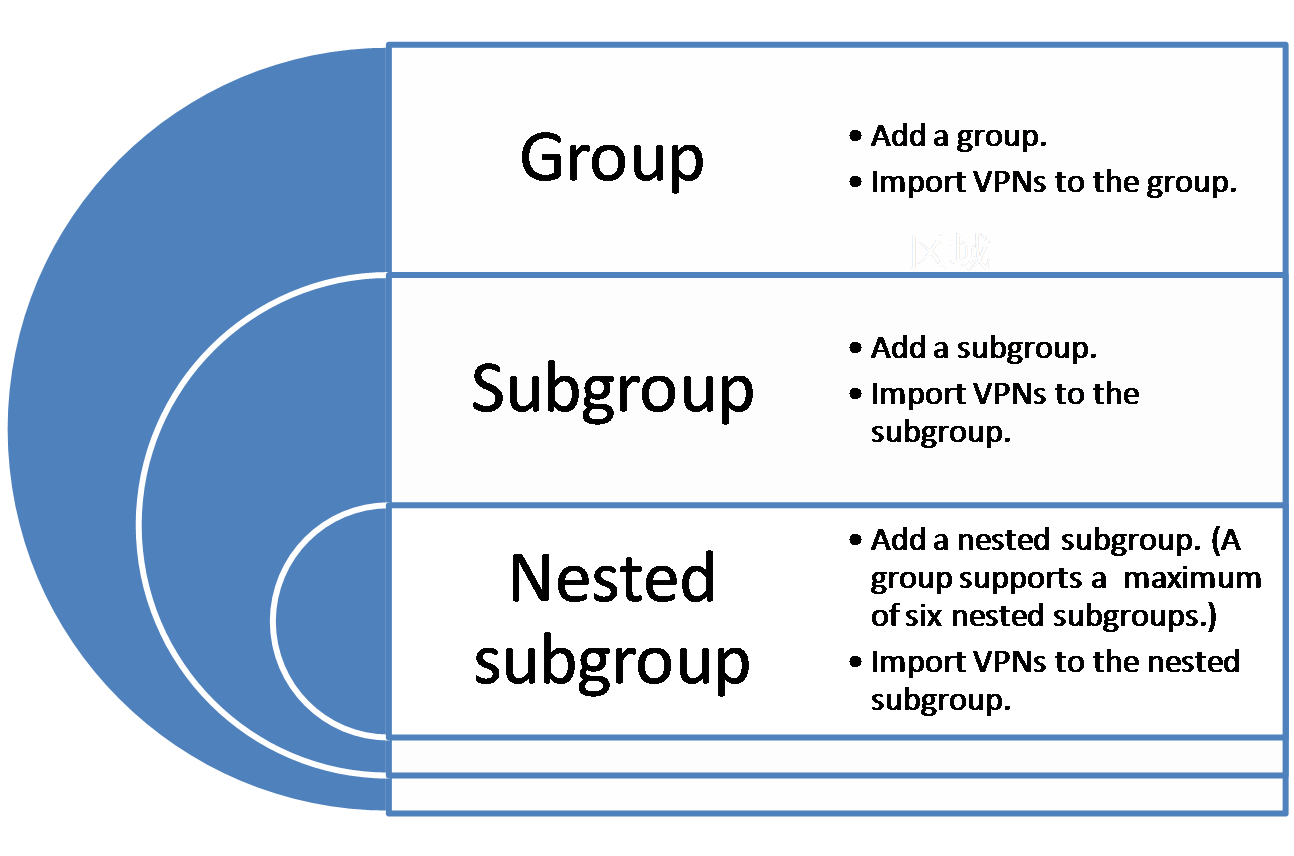
Use the group management function as follows:
1. Add a group.
2. Import one or more VPNs to the group.
3. Perform the following operations for the VPNs in the group as needed:
¡ Remove the VPNs.
¡ Audit the VPNs.
¡ Display the access topology and service topology.
4. Add subgroups to the group, and import VPNs to the subgroups.
Viewing the group list
The group list includes the groups and the VPN information.
2. From the navigation tree, select MPLS VPN Manager > VPN Resources > Group management.
The Group List page displays all groups.
¡ Status—Highest level alarm state for a PE or a CE. This field displays hyphens (--) for a group.
¡ Group/VPN Name—Name of a group or a VPN.
¡ Type—Type for an entry in the list, Group or BGP/MPLS VPN.
¡ Access Topology—Provides a link to access the VPN access topology. This field displays hyphens (--) for a group.
¡ Service Topology—Provides a link to access the VPN service topology. This field displays hyphens (--) for a group.
¡ Operation—Click
the Modify icon ![]() to modify a group, and click the Delete icon
to modify a group, and click the Delete icon ![]() to delete a
group.
to delete a
group.
3. Click Refresh on top of the Group List to view the latest Group List.
Adding a group
1. Click the Service tab.
2. From the navigation tree, select MPLS VPN Manager > VPN Resources > Group management.
The Group List page displays all groups.
3. Click the Add Group link on the upper right of the list. Alternatively, click a group name to display the lower-level group list, and then click the Add Group link on the upper right of that list.
The Add Group dialog box opens.
4. Enter the group name.
5. Click OK.
|
|
NOTE: · You can add subgroups in a group. MVM support six levels of groups at most. · Names of groups in the same level must be unique. Names of groups in different levels can be the same. |
Modifying a group
1. Click the Service tab.
2. From the navigation tree, select MPLS VPN Manager > VPN Resources > Group management.
The Group List page displays all groups.
3. Click the Modify icon ![]() for the group to
be modified. Alternatively,
click a group name to display the lower-level group list, and click the Modify icon
for the group to
be modified. Alternatively,
click a group name to display the lower-level group list, and click the Modify icon ![]() for the lower-level
group to be modified.
for the lower-level
group to be modified.
The Modify Group dialog box opens.
4. Enter the new group name.
5. Click OK.
Deleting a group
Performing this task does not affect devices or delete VPNs in a group. When a group contains subgroups or VPNs, you can still use this function to delete the group.
1. Click the Service tab.
2. From the navigation tree, select MPLS VPN Manager > VPN Resources > Group management.
The Group List page displays all groups.
3. Click the Delete
icon ![]() for the
group you want to delete. Alternatively, click a group name to display the lower-level group list, and then
click the Delete icon
for the
group you want to delete. Alternatively, click a group name to display the lower-level group list, and then
click the Delete icon ![]() for the lower-level
group to be deleted.
for the lower-level
group to be deleted.
A confirmation dialog box opens.
4. Click OK.
Importing VPNs
Perform this task to import one or more VPNs to a group or its subgroups. A VPN can belong to multiple groups.
1. Click the Service tab.
2. From the navigation tree, select MPLS VPN Manager > VPN Resources > Group management.
The Group List page displays all groups.
3. Click Import VPN on top of the Group List area. Alternatively, click a group name to display the lower-level group list, and click Import VPN on top of the Group List area.
The Import VPN dialog box opens.
4. Enter a VPN name and click Query.
5. Select the VPNs to be imported and click OK.
Modifying a VPN
1. Click the Service tab.
2. From the navigation tree, select MPLS VPN Manager > VPN Resources > Group management.
The Group List page displays all groups.
3. Click the Modify icon ![]() for the VPN that
you want to modify. Alternatively, click a group name to display the lower-level
group list, and then click the Modify icon
for the VPN that
you want to modify. Alternatively, click a group name to display the lower-level
group list, and then click the Modify icon ![]() for the VPN to be modified.
for the VPN to be modified.
The Modify VPN dialog box opens.
4. Modify the following parameters:
¡ VPN Name—Enter a new VPN name that must be unique in MPLS VPN Management.
¡ Connectivity Audit—Set whether to enable connectivity audit. Options are Periodical audit and Not Audit. If Periodical audit is set, you can modify the audit interval in the range of 2 to 168 hours. The default setting is 8 hours.
¡ Description—Modify descriptive information for the VPN.
5. Click OK.
Removing VPNs
1. Click the Service tab.
2. From the navigation tree, select MPLS VPN Manager > VPN Resources > Group management.
The Group List page displays all groups.
3. Select the VPNs to be removed and click Remove VPN. Alternatively, click a group name to display the lower-level group list, select the VPNs to be removed, and click Remove VPN.
A confirmation dialog box opens.
4. Click OK.
Auditing VPNs
Perform this task to audit the connectivity of VPNs.
1. Click the Service tab.
2. From the navigation tree, select MPLS VPN Manager > VPN Resources > Group management.
The Group List page displays all groups.
3. Select the VPNs to be audited and click Audit. Alternatively, click a group name to display the lower-level group list, select the VPNs to be audited, and click Audit.
You can view the real-time audit results in the topology or view the audit results in the VPN list after a short period of time.
VPN management
MPLS VPN Management can manage each MPLS VPN, including the Service Communities (SCs), Service Accesses (SAs), PE devices, CE devices, and service topology link for the VPN. An SC, the basic unit of a VPN, defines the VPN networking type (Full_Mesh or Hub_Spoke) and route targets (import RT and export RT). When multiple SCs share the same sites, the SCs can be combined to a VPN. An SA defines a link between a PE and a CE and indicates that a CE site is connected to the VPN. A service topology link defines the connectivity between a CE and another CE.
VPN management enables you to view, add, modify, and delete an MPLS VPN. You can manually add an MPLS VPN or automatically discover existing VPNs on the network. Then, you can display the access topology and service topology for the VPN. VPN management also supports auditing the configuration and connectivity for a VPN. The configuration audit discovers the configuration change of a device, and the connectivity audit discovers the connectivity change of a link.
Figure 10 VPN management operation process
Viewing the BGP/MPLS VPN list
1. Click the Service tab.
2. From the navigation tree, select MPLS VPN Manager > VPN Resources > VPN management.
The BGP/MPLS VPN List page displays all VPNs.
¡ Status—Alarm state for a VPN, which is the highest level alarm state for the CE and PE devices that belong to the VPN. Options are All, Unmanaged, Unknown, Normal, Warning, Minor, Major, and Critical.
¡ VPN Name—Name of a VPN. Click a VPN name link to view the VPN details.
¡ Access Topology—Provides a link to access the VPN access topology.
¡ Service Topology—Provides a link to access the VPN service topology.
¡ Audit Status—Latest audit state for VPN connectivity. Options are All, Initial status, Audit is running, and Audit completed.
¡ Audit Time—Time when the VPN connectivity was last audited.
¡ Audit Result—Result
of the last VPN connectivity audit. Options are All, Normal, Abnormal, and Unknown. When the
result is normal, click the Normal icon ![]() to display the VPN
Audit Details page. When the result is abnormal
or unknown, a number link is displayed next to the status icon. The number in
the link indicates how many links are failed. Click the number link to display the
VPN Audit Details page.
to display the VPN
Audit Details page. When the result is abnormal
or unknown, a number link is displayed next to the status icon. The number in
the link indicates how many links are failed. Click the number link to display the
VPN Audit Details page.
¡ Modify—Click
the Modify icon ![]() to modify a VPN.
to modify a VPN.
3. Click Refresh on top of the BGP/MPLS VPN List area to view the latest BGP/MPLS VPN List.
Querying a BGP/MPLS VPN
1. Click the Service tab.
2. From the navigation tree, select MPLS VPN Manager > VPN Resources > VPN management.
The BGP/MPLS VPN List page displays all VPNs.
3. Enter or select one or more of the following query criteria to search for BGP/MPLS VPNs:
¡ VPN Name—Enter a VPN name. MPLS VPN Management supports fuzzy matching for this field.
¡ Audit Status—Select an audit state from the list. Options are All, Initial status, Audit is running, and Audit completed.
¡ Status—Select an alarm state from the list. Options are All, Critical, Major, Minor, Normal, Warning, Unknown, and Unmanaged.
¡ Audit Result—Select an audit result from the list. Options are All, Normal, Abnormal, and Unknown.
4. Click Query.
The BGP/MPLS VPN List displays all VPNs matching the query criteria.
5. Click Reset to clear the query criteria and display all VPNs.
Adding a VPN
1. Click the Service tab.
2. From the navigation tree, select MPLS VPN Manager > VPN Resources > VPN management.
The BGP/MPLS VPN List page displays all VPNs.
3. Click Add on top of the BGP/MPLS VPN List area.
The Add VPN dialog box opens.
4. Configure the following parameters:
¡ VPN Name—Enter a VPN name, which must be unique in MPLS VPN Management.
¡ Connectivity Audit—Set whether to enable connectivity audit. You can select Periodical audit, and then modify the audit interval and set whether to enable Audit Inter-Spoke Unconnectivity. Alternatively, you can choose Not Audit.
¡ Description—Enter the descriptive information for the VPN.
5. Click OK.
Modifying a VPN
1. Click the Service tab.
2. From the navigation tree, select MPLS VPN Manager > VPN Resources > VPN management.
The BGP/MPLS VPN List page displays all VPNs.
3. Click the link in the Modify field for the VPN to be modified.
The Modify VPN dialog box opens.
4. Modify the following parameters:
¡ VPN Name—Enter a VPN name, which must be unique in MPLS VPN Management.
¡ Connectivity Audit—Set whether to enable connectivity audit. You can select Periodical audit, and then modify the audit interval and set whether to enable Audit Inter-Spoke Unconnectivity. Alternatively, you can choose Not Audit.
¡ Description—Enter the descriptive information for the VPN.
5. Click OK.
Removing VPNs
1. Click the Service tab.
2. From the navigation tree, select MPLS VPN Manager > VPN Resources > VPN management.
The BGP/MPLS VPN List page displays all VPNs.
3. Select the VPNs to be removed.
4. Click Remove on top of the BGP/MPLS VPN List area.
A confirmation dialog box opens.
5. Click OK.
Auditing VPNs
1. Click the Service tab.
2. From the navigation tree, select MPLS VPN Manager > VPN Resources > VPN management.
The BGP/MPLS VPN List page displays all VPNs.
3. Select the VPNs to be audited.
4. Click Audit on top of the BGP/MPLS VPN List area.
5. You can view the audit results in the topology, the VPN list, or the operation log after the audit is finished.
Modifying audit intervals
1. Click the Service tab.
2. From the navigation tree, select MPLS VPN Manager > VPN Resources > VPN management.
The BGP/MPLS VPN List page displays all VPNs.
3. Select one or more VPNs whose audit intervals must be modified.
4. Click Modify Audit Interval on top of the BGP/MPLS VPN List area.
The Modify Audit Interval dialog box opens.
5. Set whether to enable Connectivity Audit. Options are Periodical audit and Not Audit. If Periodical audit is set, you can modify the audit interval and set whether to enable Audit Inter-Spoke Unconnectivity. The value range for the audit interval is 2 to 168 hours, and the default is 8 hours.
6. Click OK.
Editing VPN details
Perform this task to display detailed information about an MPLS VPN, including SAs, SCs, PEs, CEs, and links.
1. Click the Service tab.
2. From the navigation tree, select MPLS VPN Manager > VPN Resources > VPN management.
The BGP/MPLS VPN List page displays all VPNs.
3. Click a VPN name link to display the VPN details page. The page consists of four areas: topology and audit information links, VPN basic information, VPN components, and recent 10 unrecovered alarms.
Area 1: Topology and audit information links
This area provides the operation links for viewing the access topology, service topology, and audit information.
¡ To view the access topology, click the Access Topology link on the upper right of the page. For information about the access topology, see "Global topology."
¡ To view the service topology, click the Service Topology link on the upper right of the page. For information about the service topology, see "Global topology."
¡ To view the audit information, click the Audit information link on the upper right of the page. For information about the audit information, see "Viewing VPN connectivity audit information" and "Troubleshooting."
¡ VPN Name—Name of the VPN.
¡ Audit Period—If you have set an audit period, this field displays the VPN audit period in hours. If the audit period is not set, this field displays Not audit.
¡ Abnormal Links—Number of abnormal links.
¡ Description—Description of the VPN.
¡ Audit Inter-Spoke Unconnectivity—This field is displayed when the audit period is configured. Yes indicates that inter-spoke unconnectivity is audited. No indicates that inter-spoke unconnectivity is not audited.
· Last Audit Time—Time when the last audit occurred, in the format YYYY-MM-DD hh:mm:ss. To modify VPN basic information, click Modify. The Modify VPN page opens. For more information, see "Modifying a VPN."
This area consists of six tabs, SC List, PE List, CE List, SA List, Performance, and CE-CE Link. Click the link to view the corresponding list.
¡ SC list
The SC List tab is used to view, add, modify, and delete an SC.
- SC Name—Name of the SC.
- SC Networking Type—Network type of the SC, Hub-Spoke and Full-Mesh.
- HUB's Import RT—Import RT value of the hub.
- HUB's Export RT—Export RT value of the hub.
- Modify—Click the Modify icon ![]() for the SC to be modified. When you modify an SC, you cannot modify
SC Networking Type, HUB's Import RT, and HUB's Export RT.
for the SC to be modified. When you modify an SC, you cannot modify
SC Networking Type, HUB's Import RT, and HUB's Export RT.
To add an SC, click Add on top of the list. On the page that opens, configure the parameters and click OK.
To remove an SC or SCs, select one or more SCs and click Remove on top of the list.
¡ PE list
The PE List tab is used to view, synchronize, and delete PE devices.
- Status—Alarm state of the device, Critical, Major, Minor, Warning, Normal, Unknown, or Unmanaged.
- Device Name—Name of the device. Click the PE name link to display the device details page.
- PE Type—Type of the PE device, PE, SPE, UPE, or MPE.
- AS Number—Number of the AS to which the PE device belongs.
- Region—Name of the region where the PE device resides.
- Device IP/Mask—IP address and mask of the device.
- Last Synchronization Time—Time when the last synchronization occurred.
- Synchronization Status—State of the last synchronization, Synchronizing, Success, or Failure. Click the Failed link to view the failure reasons.
To synchronize a PE or PEs, select one or more devices to be synchronized and click Synchronize. When the synchronization fails, click the Failed link to view the failure reasons.
To delete a PE or PEs, select one or more devices to be deleted, and click Remove.
To refresh the list, click Refresh to view the latest PE List.
¡ CE list
The CE List tab is used to view, synchronize, and delete CE devices.
- Status—Alarm state of the device, Critical, Major, Minor, Warning, Normal, Unknown, or Unmanaged.
- Device Name—Name of the device. Click the name link to display the Device Details page.
- CE Type—Type of the CE device, CE, VMCE, or MCE.
- Device IP—IP address of the device.
- Mask—Mask of the device.
- Last Synchronization Time—Time when the last synchronization occurred.
- Synchronization Status—Last synchronization state, Synchronizing, Success, or Failure. Click the Failed link to view the failure reasons.
To synchronize a CE or CEs, select one or more devices to be synchronized and click Synchronize. When the synchronization fails, click the Failed link to view the failure reasons.
To delete a CE or CEs, select one or more devices to be deleted, and click Remove.
To refresh the list, click Refresh to view the latest CE List.
¡ SA list
The SA List tab is used to view, add, deploy, undeploy, and delete SA links.
- SA Name—Name of the SA.
- Attached VPN—Name of the VPN to which the SA belongs.
- Link Status—State of the link, Normal, Configuration changed, Configuration changes, Link invalid, Undeployed, Deploying, Deployment failure, or Undeployment failure.
- PE Name—Name of the PE device. Click the PE name link to view the PE details.
- CE Name—Name of the CE device. Click the CE name link to view the CE details.
To add an SA, click Add. For more information, see "Adding/Modifying an SA."
To remove SAs, select one or more SAs, click Remove.
To deploy SAs, select one or more SAs, click Deploy.
To undeploy SAs, select one or more SAs, click Undeploy.
¡ Performance
The Performance tab consists of two graphs for the incoming traffic report and the outgoing traffic report, and supports exporting the reports. The incoming traffic report displays the following:
Graph type switch buttons
On the upper left of the graph are the Table, Line Chart, Bar Chart, and Sampling Point buttons. Click the buttons to view the report in different charts. The default setting is displaying data in a line chart.
Click Export as Excel on the upper right of the graph to export the report in the Excel format. You can also click Export as PDF, Export as HTML, or Export as TXT to export the report in the corresponding format. On the window that opens, click Traffic Report and select a save path. After the report is saved, click Close in the window to return to the Performance tab.
The x coordinate in the line chart represents the time and the y coordinate represents the traffic. The report shows the trend of the incoming traffic for the MPLS VPN.
Incoming traffic list contents
- Monitored Object—Name of the VPN that is monitored.
- Min. Value—Minimum value of the monitored traffic.
- Max. Value—Maximum value of the monitored traffic.
- Current Value—Current value of the monitored traffic.
- Average Value—Average value of the monitored traffic.
- Min. Value at—Time when the minimum value of the monitored traffic appears.
- Max. Value at—Time when the maximum value of the monitored traffic appears.
- Valid Sampling Point—Number of the monitored valid sampling points.
The function and format of the outgoing traffic report are the same as those of the incoming traffic report.
¡ CE-CE link
- Attached SC of the link—SC to which the CE-CE link belongs.
- Local CE—Name and IP address of the local CE.
- Opposite CE—Name and IP address of the remote CE.
To add a CE-CE link to the service topology:
- Click Add at the top of the CE-CE list. The Add Topology Link page opens.
- For the Left Node field, click Select. The Select CE window opens. Select a CE device and click OK to return to the Add Topology Link page.
- For the SC field, click Select. The Select SC window opens. Enter the SC name in the SC Name field and click Query. Select an SC in the SC List and click OK to return to the Add Topology Link page.
- Click Add on top of the Right Node List area. The Select CE window opens. Select the CE name in the CE Name field and click Query. Select one or more CE devices in the CE List and click OK to return to the Add Topology Link page. Repeat this step to add multiple right nodes.
- Click OK.
To remove a CE-CE link or links, select one or more links and click Remove.
Area 4: Recent 10 unrecovered alarms
This area is always displayed no matter which tab you click.
Recent 10 unrecovered alarms contents
¡ Severity—Alarm level. Options are Critical, Major, Minor, Warning, and Info.
¡ Source—Device that sends an alarm message.
¡ Alarm Information—Detailed information about the alarm.
¡ Alert Time—Time when the alarm occurred.
¡ Device Role—Role of the device that sends the alarm message. Options are P, NPE, SPE, UPE, MPE, VPE, CE, VMCE, or MCE.
To view all alarms, click the All Alarms link on the upper right of the area. For information about the all alarms function, see H3C Intelligent Management Center v7.3 Enterprise and Standard Platform Administrator Guide.
Viewing VPN connectivity audit information
MPLS VPN Management supports auditing VPN connectivity and auditing the inter-spoke unconnectivity for a VPN if the VPN networking type is Hub-Spoke.
To view VPN connectivity audit information:
1. Click the Service tab.
2. From the navigation tree, select MPLS VPN Manager > VPN Resources > VPN management.
The BGP/MPLS VPN List page displays all VPNs.
3. Click a VPN name link to display the VPN details page.
4. Click the Audit Information link on the upper right of the page. The VPN Audit Details page opens.
5. The VPN Link Audit Information list and the Inter-Spoke Unconnectivity Audit Information list display detailed information about the VPN audit. If you have disabled Audit Inter-Spoke Unconnectivity when adding the VPN, this page does not display the Inter-Spoke Unconnectivity Audit Information list.
6. Enable Display All Links on the upper right of the lists. The two lists display all links with the connectivity state being Normal, Unknown, or Disconnected. If you do not enable Display All Links, the two lists only display links with the connectivity state being Unknown or Disconnected.
VPN Link Audit Information contents
¡ Audit Result—Result of the last connectivity audit, Normal, Abnormal, or Unknown.
¡ Connectivity Status—Connectivity state of the link. Options are Connected, Disconnected, and Unknown.
¡ Attached SC of the link—SC to which the link belongs.
¡ Local CE—Name and IP address of the local CE.
¡ Opposite CE—Name and IP address of the remote CE.
¡ Audit Status—Audit state for the link. Options are Initial Status, Audit Completed, and Audit is running.
¡ Last Audit Time—Time when the last audit occurred.
¡ Troubleshooting—Click the Troubleshooting
icon ![]() in this
field for the disconnected link to display the Troubleshooting page. For information
about troubleshooting, see "Troubleshooting."
in this
field for the disconnected link to display the Troubleshooting page. For information
about troubleshooting, see "Troubleshooting."
To audit a link, select the link to be audited and click Audit.
Inter-Spoke Unconnectivity Audit Information contents
¡ Audit Result—Result of the last connectivity audit. Options are Normal, Abnormal, and Unknown.
¡ Connectivity Status—Connectivity state of the link. Options are Connected, Disconnected, and Unknown.
¡ Attached SC of the link—SC to which the link belongs.
¡ Local CE—Name and IP address of the local CE.
¡ Opposite CE—Name and IP address of the remote CE.
¡ Audit Status—Audit state for the link. Options are Initial Status, Audit Completed, and Audit is running.
¡ Last Audit Time—Time when the last audit occurred.
7. Click the VPN Details link on the upper right of the page to return to the VPN details page.
Troubleshooting
Perform this task to automatically find the faults and causes for disconnected links discovered by connectivity audit.
This function is supported on H3C Comware V3 devices, Huawei devices, and some Cisco devices, and it is applicable only when OSPF is used between a PE and a CE.
1. Click the Service tab.
2. From the navigation tree, select MPLS VPN Manager > VPN Resources > VPN management.
The BGP/MPLS VPN List page displays all VPNs.
3. Click a VPN name link to display the VPN details page.
4. Click the Troubleshooting
icon ![]() for a disconnected link in the VPN Link Audit Information list.
for a disconnected link in the VPN Link Audit Information list.
5. The Troubleshooting List displays the operation and result for troubleshooting.
¡ Time—Time when the troubleshooting began.
¡ Source—Source device for the troubleshooting.
¡ Destination—Destination device for the troubleshooting.
¡ Result—Result of the troubleshooting, which provides troubleshooting recommendations.
6. Click Back to return to the VPN Audit Details page.
SA management
This function manages the link between a CE and a PE. You can use this function to add, modify, remove, deploy, and undeploy an SA.
Figure 11 SA management operation process
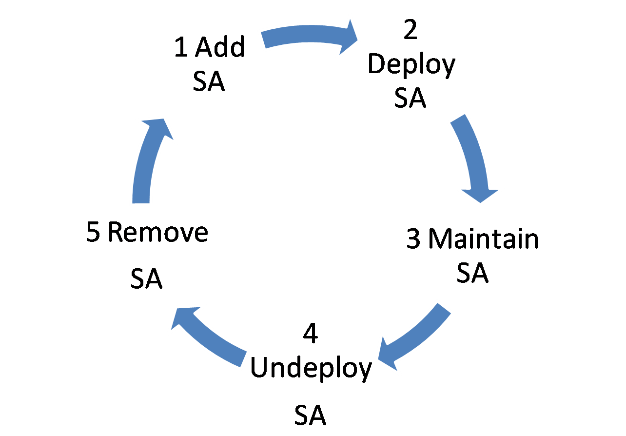
1. Add an SA when a customer site is connected to a VPN.
2. Deploy the newly added SA to the PE and CE devices.
3. View detailed information and configuration changes for the SA, and modify the SA,.
4. Undeploy the SA when the customer site is not used any more.
5. Remove one or more SAs from MPLS VPN Management.
Viewing the SA list
1. Click the Service tab.
2. From the navigation tree, select MPLS VPN Manager > VPN Resources > SA management.
The SA List page displays all SAs.
¡ SA Name—Name of the SA, in the format of PE device name (PE device's IP address)-CE device name (CE device's IP address).
¡ Attached VPN—VPN to which the SA belongs.
¡ Link Status—State of the link. Options are Normal, Configuration changed, Configuration changes, Link invalid, Undeployed, Deploying, Deployment failure, and Undeployment failure.
¡ PE Name—Name of the PE device. Click the PE name link to view the PE details.
¡ CE Name—Name of the CE device. Click the CE name link to view the CE details.
¡ Operation—Provides the following operation links:
- Click the Details icon ![]() to view detailed
SA information.
to view detailed
SA information.
- Click the Modify icon ![]() to modify an SA.
to modify an SA.
- Click the Change
icon ![]() to view the change of the SA configuration.
to view the change of the SA configuration.
3. Click Refresh to view the latest SA List.
Querying SAs
1. Click the Service tab.
2. From the navigation tree, select MPLS VPN Manager > VPN Resources > SA management.
The SA List page displays all SAs.
3. Enter or select one or more of the following query criteria:
¡ Query Type—Select one query type from All, SA Name, Attached VPN, and Link Status.
¡ Query Condition—Enter information about the selected query type in the query criteria field.
4. Click Query.
The SA List displays all SAs matching the query criteria.
5. Click Reset to clear the query criteria and display all SAs.
Adding/Modifying an SA
As a best practice, perform auto discovery to make sure the link is not deployed in the network before deploying a link. Before you perform auto discovery, synchronize devices to make sure you obtain the most recent configuration of the devices.
1. Click the Service tab.
2. From the navigation tree, select MPLS VPN Manager > VPN Resources > SA management.
The SA List page displays all SAs.
3. Click Add at the top of the SA list. Alternatively,
click the Modify icon ![]() in the Operation field for the SA to be modified.
in the Operation field for the SA to be modified.
4. Select a PE for the SA:
a. Click Select PE on the Select PE and VPN page. The Select Devices page opens. There are two methods for selecting device, By View or using the Advanced option. See "Adding devices by view" and "Adding devices by advanced query."
b. Highlight the device you want to select and do one of the following:
- To add the devices to the Selected Devices
list, click Add selected
![]() .
.
- To remove one or more devices, select the devices and click Remove selected ![]() .
.
c. Confirm that the device you found has been added.
d. Click OK to return to the Select PE and VPN page.
5. Select a VPN for the SA:
a. Click Select VPN on the Select PE and VPN page.
The Select VPN page opens.
b. Enter the VPN name and click Query.
c. Select a VPN from the list.
d. Click OK to return to the Select PE and VPN page.
6. Click Next.
7. Select an SC for the SA and the join type for the PE device to connect to the VPN.
The page consists of two lists, SC of Current VPN and Selected SC.
SC of Current VPN contents
¡ SC Name—Name of the SC.
¡ Networking Type—Networking type of the SC, Hub-Spoke or Full-Mesh.
¡ HUB's Import RT—Import RT value of the hub.
¡ HUB's Export RT—Export RT value of the hub.
Selected SC contents
¡ SC Name—Name of the SC.
¡ Join Type—Join type for the SC, Hub or Spoke.
¡ Networking Type—Networking type of the SC, Hub-Spoke or Full-Mesh.
¡ HUB's Import RT—Import RT value of the hub.
¡ HUB's Export RT—Export RT value of the hub.
a. Select one or more SCs in the SC of Current VPN list.
b. Select a handling method, Add by HUB, Add by Spoke, or Release SC. The selected SC is added to the Selected SC list.
c. Click Next.
8. Configure the PE and CE:
a. To configure the PE:
i Select an interface from the Interface Description list.
ii Enter the interface IP address and subnet mask in the Interface IP/Mask field.
b. (Optional.) Configure a non-managed CE manually or automatically. MPLS VPN Management supports virtual CEs (VCEs) to represent CEs that cannot be managed.
To automatically configure a non-managed CE, enable Create Non-managed CE automatically. The system automatically creates a non-managed CE for the link that no CE is connected to.
To manually configure a non-managed CE, click the Add Non-Managed CE link on the upper right of the page. The Add Non-Managed CE page opens.
i Enter the device name in the Device Name field.
ii Select the CE type from the Type list. Options are CE and VMCE.
iii Click Add on the upper right of the interface configuration page. Enter the interface description, and interface IP address and mask in the dialog box that opens. Click OK to return to the Add Non-Managed CE page.
iv Click OK to return to the Interface Configuration page.
c. To configure the CE:
i Select a CE from the Device Name list. The CE can be a managed CE or the created non-managed CE.
ii Select an interface from the Interface Description list.
iii Enable Auto filter interface. The Interface Description list displays only the interfaces of the CE that is in the same subnet as the PE.
iv Enable Filter out interface without IP address. The Interface Description list displays only the interfaces that have IP addresses.
v Enter the IP address and subnet mask for the selected interface in the Interface IP/Mask field.
d. Click Next.
9. Configure the VRF information:
a. The system automatically generates a default VRF name in the VRF Name field. You can change the VRF name. To restore the default VRF name, click the Restore Default link.
b. The system automatically generates a default RD value in the RD Value field. You can change the value.
c. The system uses the VRF in the Existing VRF list as the newly deployed VRF.
d. The Configure route field is displayed when the selected CE is a managed CE. You can configure a static route or the OSPF routing protocol in this field. Enable Configure route and click Next to go to step 10. Disable configure route and click Next to step 11.
e. Click Next.
10. Configure the route between the PE and the CE:
a. Select a routing protocol. Options are Static and OSPF.
b. Configure the PE.
i Enter the destination IP and mask in the Destination IP/Mask field.
ii Click Add. Repeat the steps to add multiple routes.
c. Configure the CE.
i Enter the destination IP and mask in the Destination IP/Mask field.
ii Click Add. Repeat the steps to add multiple routes.
d. Click Next.
The Summary page consists of the Basic Information, Configuration command, and Deploy Immediately areas. The Basic Information and Configuration command areas help you verify the configuration before you execute the configuration commands.
The Basic Information area displays the names of the PE device and the CE device. If you configure a route between the PE and the CE, this area also displays the route type.
The Configuration command area displays the configuration commands to be executed on the PE and the CE.
11. If you enable Deploy Immediately, the configuration is deployed immediately onto the devices. Return to the SA List page, and an SA with the link state being Deploying is displayed. If you disable Deploy Immediately, click OK to return to the SA List page. An SA with the link state being Undeployed is displayed. You must manually deploy it.
12. Click OK.
Removing SAs
1. Click the Service tab.
2. From the navigation tree, select MPLS VPN Manager > VPN Resources > SA management.
The SA List page displays all SAs.
3. Select the SAs to be removed.
4. Click Remove.
A confirmation dialog box opens.
5. Click OK.
Deploying SAs
1. Click the Service tab.
2. From the navigation tree, select MPLS VPN Manager > VPN Resources > SA management.
The SA List page displays all SAs.
3. Select the SAs to be deployed.
4. Click Deploy.
5. Click OK.
The Deployment Status
field displays the deployment result. The ![]() link indicates a deployment failure. Click the link to view which
commands are failed to be executed.
link indicates a deployment failure. Click the link to view which
commands are failed to be executed.
Undeploying SAs
1. Click the Service tab.
2. From the navigation tree, select MPLS VPN Manager > VPN Resources > SA management.
The SA List page displays all SAs.
3. Select one or more SAs to be undeployed.
4. Click Undeploy.
A confirmation dialog box opens.
5. Click OK.
Management VPN
After a management VPN is configured, the system automatically filters the RT attributes of the management VPN when the system performs auto discovery and adds an SA.
Configuring a management VPN
Perform this task to configure the SC information for a management VPN.
To configure a management VPN:
1. Click the Service tab.
2. From the navigation tree, select MPLS VPN Manager > VPN Resources > Mgt. VPN Configuration.
The Mgt. VPN Configuration page opens.
3. Configure the following parameters:
¡ Status—Select whether to enable management VPN filtering. Options are Enabled and Disabled. If you enable filtering management VPNs, configure the hub's import RT and export RT. If you disable filtering management VPNs, go to step 4.
¡ HUB's Import RT—Enter the import RT value for the management VPN.
¡ HUB's Export RT—Enter the export RT value for the management VPN.
4. Click OK.
VPN devices
This function manages PE and CE devices. You can synchronize, view, and query the devices. In addition, you can switch regions for a PE device, and manage managed CEs and non-managed CEs.
VPN device general view
MPLS VPN Management provides the general view of the statistics about devices counted by device type and alarm level.
To display the VPN device general view page:
2. From the navigation tree, select MPLS VPN Manager > VPN Devices.
The VPN Device General View displays the VPN device charts.
Figure 12 VPN devices
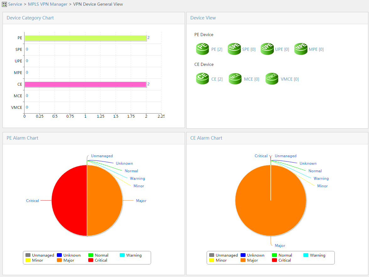
You can view the statistics of all devices and failures on this page.
· The device type pie charts show the number of PEs, SPEs, UPEs, MPEs, CEs, MCEs, and VMCEs.
· The device view chart shows the device type by number in descending order and the number of devices that belong to each type.
· The PE device alarm pie chart shows the number of the PE devices in each alarm state.
· The CE device alarm pie chart shows the number of the CE devices in each alarm state.
You can click a chart to display the device list and manage the devices in the list.
PE device list
Use this function to query, synchronize, switch, remove a PE device, and view the VPN information for the device.
|
|
NOTE: The initial PE device list is blank. Before you view and manage PE devices, use the region management function to import PE devices to MPLS VPN Management. |
Viewing the PE device list
1. Click the Service tab.
2. From the navigation tree, select MPLS VPN Manager > VPN Devices > PE Device List.
The PE Device List page displays all PE devices.
PE Device List contents
¡ Status—Alarm state of the device. Options are Critical, Major, Minor, Warning, Normal, Unknown, and Unmanaged.
¡ Device Name—Name of the device. Click the PE name link to view the PE details.
¡ PE Type—Type of the PE device. Options are PE, SPE, UPE, and MPE.
¡ AS Number—Number of the AS to which the PE device belongs.
¡ Region—Name of the region.
¡ Device IP/Mask—Management IP and mask of the PE device.
¡ Last Synchronization Time—Time when the last synchronization occurred.
¡ Synchronization Status—Synchronization state of the PE device, Synchronizing, Success, or Failure.
¡ View—Click
the View icon ![]() to view the SA information and alarm information for the device in the
PE VPN Information page.
to view the SA information and alarm information for the device in the
PE VPN Information page.
3. Click Refresh to view the latest PE Device List.
Querying PE devices
1. Click the Service tab.
2. From the navigation tree, select MPLS VPN Manager > VPN Devices > PE Device List.
The PE Device List page displays all PE devices.
3. Enter or select one or more of the following query criteria:
¡ Device Name—Enter a PE name. MPLS VPN Management supports fuzzy matching for this field.
¡ Status—Select the alarm state of the PEs to be queried. Options are All, Critical, Major, Minor, Warning, Normal, Unknown, and Unmanaged.
¡ Device IP—Enter the PE IP address. MPLS VPN Management supports fuzzy matching for this field.
¡ PE Type—Select a PE type. Options are All, PE, SPE, UPE, and MPE.
4. Click Query.
The PE Device List displays all PE devices matching the query criteria.
5. Click Reset to clear the query criteria and display all PE devices.
Synchronizing PE devices
1. Click the Service tab.
2. From the navigation tree, select MPLS VPN Manager > VPN Devices > PE Device List.
The PE Device List page displays all PE devices.
3. Select one or more devices to be synchronized and click Synchronize.
4. The Synchronization Status field in the list displays the synchronization process of the devices.
5. Click Refresh to view the latest synchronization result.
Switching PEs between regions
Perform this task to move PE devices from a region to another region in the same AS. P devices do not support this function.
To switch PEs between regions:
1. Click the Service tab.
2. From the navigation tree, select MPLS VPN Manager > VPN Devices > PE Device List.
The PE Device List page displays all PE devices.
3. Select one or more devices to be switched and click Switch.
The AS/Region window opens.
4. Select a region.
5. Click OK.
Removing PE devices
Perform this task to remove PE devices from MPLS VPN Management.
1. Click the Service tab.
2. From the navigation tree, select MPLS VPN Manager > VPN Devices > PE Device List.
The PE Device List page displays all PE devices.
3. Select one or more devices to be removed from the list and click Remove.
A confirmation dialog box opens.
4. Click OK.
CE device list
Use this function to query, synchronize, switch, and remove a CE device. You cannot synchronize a non-managed CE.
Viewing the CE device list
1. Click the Service tab.
2. From the navigation tree, select MPLS VPN Manager > VPN Devices > CE Device List.
The CE Device List page displays all CE devices.
CE Device List contents
¡ Status—Alarm state of the device, Critical, Major, Minor, Warning, Normal, Unknown, or Unmanaged.
¡ Device Name—Name of the device. Click the CE name link to view the CE details.
¡ CE Type—Type of the CE device, CE, VMCE, or MCE.
¡ Device IP—IP address of the CE device.
¡ Mask—Mask for the CE device.
¡ Last Synchronization Time—Time when the last synchronization occurred.
¡ Synchronization Status—State of the last synchronization, Synchronizing, Success, or Failure. Click the Failed link, and a prompt that indicates the failure reasons is displayed.
¡ Modify—Click the Modify
icon ![]() to
modify a non-managed CE. This icon is not displayed for a managed CE.
to
modify a non-managed CE. This icon is not displayed for a managed CE.
3. Click Refresh to view the latest CE Device List.
Querying CE devices
1. Click the Service tab.
2. From the navigation tree, select MPLS VPN Manager > VPN Devices > CE Device List.
The CE Device List page displays all CE devices.
3. Enter or select one or more of the following query criteria:
¡ Device Name—Enter the name of the CE. MPLS VPN Management supports fuzzy matching for this field.
¡ Status—Select the alarm state of the CEs to be queried. Options are All, Critical, Major, Minor, Warning, Normal, Unknown, and Unmanaged.
¡ Device IP—Enter the IP address of the CE. MPLS VPN Management supports fuzzy matching for this field.
¡ CE Type—Select the type of the CE. Options are All, CE, VMCE, and MCE.
4. Click Query.
The CE Device List displays all CE devices matching the query criteria.
5. Click Reset to clear the query criteria and display all CE devices.
Importing CE devices
Perform this task to import CE devices to MPLS VPN Management. Before importing the devices, make sure the devices to be imported meet the following conditions:
· Enables with SNMP and are enabled with SNMP.
· Added into IMC, and recognized and managed by IMC.
· Not imported as P or PE devices.
1. Click the Service tab.
2. From the navigation tree, select MPLS VPN Manager > VPN Devices > CE Device List.
The CE Device List page displays all CE devices.
3. Click Import on top of the CE Device List area.
The Import Device page opens.
4. Select the CE type from the box next to Please select CE type to be imported. Options are CE, VMCE, and MCE.
5. Click Select to select the CE devices to be imported.
There are two methods for selecting devices, By View or using the Advanced option. See "Adding devices by view" and "Adding devices by advanced query."
6. Highlight the devices you want to select and do one of the following:
¡ To
add the devices to the Selected Devices list, click
Add selected ![]() .
.
¡ To
select all of the devices displayed in the Devices Found
list, click Add all ![]() .
.
¡ To
remove one or more devices, select the devices and click Remove
selected ![]() .
.
¡ To
remove all of the selected devices, click Remove all
![]() .
.
7. Confirm that the devices you found have been added.
8. Click OK to display the Import Device page. The selected devices now appear in the page.
9. Check the imported devices:
¡ To add more devices, repeat step 5.
¡ To delete devices, select one or more devices in the list, and click Remove.
10. Click OK.
The page for import progress opens. You can view the import process and result.
Adding/Modifying a non-managed CE
Some CE devices cannot be managed by IMC. Perform this task to create a virtual CE to represent a non-managed CE in the MPLS VPN topology to keep the topology complete.
To add/modify a non-managed CE:
1. Click the Service tab.
2. From the navigation tree, select MPLS VPN Manager > VPN Devices > CE Device List.
The CE Device List page displays all CE devices.
3. Click Add Non-Managed CE on the upper right of the CE Device List
area to display the Add
Non-Managed CE page. Alternatively, click the Modify icon ![]() in the Operation field
for the CE to be modified to display the Modify Non-Managed CE page.
in the Operation field
for the CE to be modified to display the Modify Non-Managed CE page.
4. Enter the device name in the Device Name field.
5. Select the CE type from the Type list. Options are CE and VMCE.
You cannot select the CE type when you display the Modify Non-Managed CE page.
6. Click Add in the Interface List area.
The Add Non-Managed CE Interface page opens.
7. Perform the following configurations on the Add Non-Managed CE Interface page:
a. Enter the interface description in the Interface Description field.
b. Enter the interface IP address and mask in the Interface IP/Mask field.
c. Click OK to return to the Add/Modify Non-Managed CE page.
Repeat the steps to add multiple CE interfaces. To remove an interface or interfaces, select one or more interfaces in the Interface List and click Remove. You cannot remove an interface that is already connected to the PE device.
8. Click OK to return to the CE Device List.
Synchronizing CE devices
1. Click the Service tab.
2. From the navigation tree, select MPLS VPN Manager > VPN Devices > CE Device List.
The CE Device List page displays all CE devices.
3. Select one or more devices to be synchronized and click Synchronize.
4. The Synchronization Status field in the list displays the synchronization process of the devices.
5. Click Refresh to view the latest synchronization result.
Removing CE devices
Perform this task to remove CE devices, including non-managed CEs, from MPLS VPN Management.
1. Click the Service tab.
2. From the navigation tree, select MPLS VPN Manager > VPN Devices > CE Device List.
The CE Device List page displays all CE devices.
3. Select one or more devices to be removed in the list and click Remove.
A confirmation dialog box opens.
4. Click OK.
Auto discovery
The auto discovery function collects VPN information from devices, uses model calculation to obtain the existing VPNs and links, and draws the topology. VPNs that are discovered automatically are added to MPLS VPN Management. You can modify and delete them. Also, you can perform the link deployment and removing, and traffic monitoring operations.
To discover VPNs automatically:
1. Click the Service tab.
2. From the navigation tree, select MPLS VPN Manager > Auto Discovery.
The auto discovery configuration guide page opens.
3. Select PE devices:
a. Configure auto discovery parameter settings:
i Select the Remove all invalid links box.
ii Select the Synchronize PE device before auto discovery box.
b. Configure auto discovery range settings:
i Click Select PE.
The Select Devices dialog box opens.
There are two methods for selecting devices, By View or using the Advanced option. See "Adding devices by view" and "Adding devices by advanced query."
ii Highlight the devices you want to select and do one of the following:
- To add the devices to the Selected Devices
list, click Add selected ![]() .
.
- To select all of the devices displayed in the Devices
Found list, click Add all ![]() .
.
- To remove one or more devices, select the devices and click Remove selected ![]() .
.
- To remove all of the selected devices, click Remove
all ![]() .
.
iii Confirm that the devices you found have been added.
iv Click OK.
v Click the Delete icon ![]() for the device to be removed from the device list.
for the device to be removed from the device list.
vi Click Remove All for all devices to be removed from the device list.
c. Click Auto Discovery.
4. Discover VPNs automatically.
A process bar for VPN auto discovery is displayed. When the auto discovery is finished, the page for VPN selection opens.
5. Select the VPNs whose links are to be configured.
a. View the VPN List Found.
VPN List Found contents
- Status—State of the VPN, Existing, New VPN, or Conflict. Existing indicates that a new link for the VPN is found. New VPN indicates that the VPN is new. Conflict indicates that the VPN has different SC information from that discovered last time.
- VPN Name—Name of the VPN.
- VPN Type—Type of the VPN. The value can be BGP/MPLS VPN.
- VPN Description—Description of the VPN.
b. Select one or more VPNs in the VPN List Found.
c. Click Next.
a. Enable Create Non-managed CE automatically. Then, the system automatically creates a non-managed CE for a link without any CE device.
b. View the New Link List.
New Link List contents
- Device Name—Name and IP address of the PE device.
- VRF Name—Name of the found VRF.
- Attached VPN of Link—Name of the VPN to which the link belongs.
- PE Interface—Name of the interface on the PE device.
- MCE Name—Name of the MCE. This field is blank for a non-MCE network.
- CE Name—Name of the CE device.
- Configure—Click the Configure icon ![]() to display the page for configuring a link. For more information,
see step 7.
to display the page for configuring a link. For more information,
see step 7.
c. Select one or more links to be added to MPLS VPN Management.
d. Click Finish.
The Summary page opens.
You can use this step to configure the CE devices for the new link. The configuration ways vary with the network types.
a. Method 1: Add a non-managed CE manually.
i Click the Add Non-Managed CE link on the upper right of the Configure Link page. The Add Non-Managed CE page opens.
ii Enter the name of the CE device in the Device Name field.
iii Select the type of the CE device from the Type list. Options are CE and VMCE.
iv Click Add on the top of the Interface List area. The Add Interface page opens.
v Enter the interface description in the Interface Description field.
vi Enter the IP address and mask of the interface in the Interface IP/Mask field.
vii Click OK to return to the Add Non-Managed CE page.
b. Method 2: Add a VMCE.
i Click the Add VMCE Configuration link on the upper right of the Configure Link page. The VMCE Configuration section is displayed.
ii Select a VMCE device from the Device Name list.
iii Select the interface that connects to the PE device from the Interface connected to upper device list.
iv Select the interface that connects to the CE device from the Interface connected to down device list.
v Click add VMCE below Interface connected to down device to add a VMCE. Click delete VMCE to delete a VMCE.
c. Configure a CE:
i Select a CE device from the Device Name list. The Device Name lists the existing CEs in the system and the non-managed CEs that you added to MPLS VPN Management.
ii Select an interface from the Interface Description list.
There are two filtering rules below Interface Description: Automatically Filter Interface and Filter Interface without IP Address. If you enable Automatically Filter Interface, the Interface Description lists only the CE interfaces that are in the same subnet as the PE's interfaces. If you enable Filter Interface without IP Address, the Interface Description lists only interfaces that have IP addresses.
iii Enter the interface IP address and mask in the Interface/Mask field.
8. Click OK to return to the VRF Binding Relationship Configuration page.
The Configured VPN Link Result displays the VPN link configuration results.
Configured VPN Link Result contents
· Device Name—Name of the PE device.
· VRF Name—Name of the VRF.
· PE Interface—Name of the PE device interface that connects to the VPN link.
· MCE Interface—Name of the MCE. This field is blank for a non-MCE network.
· CE Name—Name of the CE device.
· Result—Result of the VPN link configuration, Success or Failure.
Global topology
MPLS VPN Management provides the global topology for the entire MPLS VPN, and the access topology and service topology for each VPN. An access topology shows the connections between PEs and CEs, and a service topology shows the connections between CEs for an MPLS VPN. Through MPLS VPN Management, you can view the connections in an MPLS VPN and perform some visible operations, such as connectivity detection, highlighting an MPLS VPN, and service deployment.
Entering global topology
Global topology shows the entire MPLS VPN, including the connection state of CEs, PEs, ASs, regions, and subregions.
To display the VPN global topology page:
2. From the navigation tree, select MPLS VPN Manager > Global Topology.
The VPN Global Topology page opens.
Entering access topology
You can view the VPN information for a PE, test the connectivity, and remove a PE and a CE from a VPN. MPLS VPN Management provides multiple methods to display the access topology.
Method 1: From the global topology
1. Click the Service tab.
2. From the navigation tree, select MPLS VPN Manager > Global Topology.
The VPN Global Topology page opens.
3. From the navigation tree on the page, select MPLS VPN > VPNFullMesh > Access Topology. Double-click the access topology node below an MPLS VPN.
Method 2: From the BGP/MPLS VPN list
1. Click the Service tab.
2. From the navigation tree, select MPLS VPN Manager > VPN Resources > VPN management.
The BGP/MPLS VPN List page displays all VPNs.
3. Click the Access Topology link for a VPN.
Method 3: From the VPN details page
1. Click the Service tab.
2. From the navigation tree, select MPLS VPN Manager > VPN Resources > VPN management.
The BGP/MPLS VPN List page displays all VPNs.
3. Click a VPN name link to display the VPN details page.
4. Click the Access Topology link on the upper right of the page.
Entering service topology
You can remove a CE from a VPN and test the connectivity. MPLS VPN Management provides you multiple methods to display the service topology.
Method 1: From the global topology
1. Click the Service tab.
2. From the navigation tree, select MPLS VPN Manager > Global Topology.
The VPN Global Topology page opens.
3. From the navigation tree on the page, select MPLS VPN > VPNFullMesh > Service Topology. Double-click the service topology node below an MPLS VPN.
Method 2: From the BGP/MPLS VPN list
1. Click the Service tab.
2. From the navigation tree, select MPLS VPN Manager > VPN Resources > VPN management.
The BGP/MPLS VPN List page displays all VPNs.
3. Click the Service Topology link for a VPN.
Method 3: From the VPN details page
1. Click the Service tab.
2. From the navigation tree, select MPLS VPN Manager > VPN Resources > VPN management.
The BGP/MPLS VPN List page displays all VPNs.
3. Click a VPN name link to display the VPN details page.
4. Click the Service Topology link on the upper right of the page.
Topology operations
Table 1 shows the operations that you can perform for MPLS VPN on the topologies. For information about other operations that can be performed on the topologies, see H3C Intelligent Management Center v7.3 Enterprise and Standard Platform Administrator Guide.
Table 1 Support for MPLS VPN operations on topologies
|
Operations |
Global topology |
Access topology |
Service topology |
|
View device VPN information |
Yes |
Yes |
No |
|
View VPN link information |
Yes |
Yes |
No |
|
Highlight/Cancel highlight a VPN |
Yes |
No |
No |
|
Auto discovery |
Yes |
No |
No |
|
Deploy a service |
Yes |
No |
No |
|
Deploy all links |
Yes |
No |
No |
|
Remove deployment configurations |
Yes |
No |
No |
|
Remove a device from a VPN |
Yes |
Yes |
Yes |
|
Test VPN connectivity between devices |
Yes |
Yes |
Yes |
|
Audit link connectivity |
No |
No |
Yes |
|
Query connectivity information |
No |
No |
Yes |
|
Troubleshoot |
No |
No |
Yes |
|
Audit all VPN connectivity |
No |
No |
Yes |
|
Analyze MPLS VPN traffic |
No |
Yes |
Yes |
Viewing device VPN information
Perform this task to go to the device VPN information page from the VPN global topology page, and to view detailed VPN information for a device. This function is available on the global topology and an access topology. Take the global topology for example:
1. Click the Service tab.
2. From the navigation tree, select MPLS VPN Manager > Global Topology.
The VPN Global Topology page opens.
3. Right-click a PE device and select Device VPN Information from the shortcut menu.
The PE VPN Information page opens.
4. The page consists of the Found SA List area and the Recent 10 unrecovered alarms area.
Found SA List contents
¡ VRF—VRF information, including VPN instance name, RD, import RTs, and export RTs.
¡ Bound Interface—Name and IP address of the interface that is bound with the VRF.
¡ Connected MCE—Name and IP address of the MCE that connects to the VRF.
¡ Connected CE—Name and IP address of the CE that connects to the VRF.
¡ Configure Audit Status—Last audit configuration result. Options are Link invalid, Configuration unchanged, and Configuration changed.
Recent 10 unrecovered alarms contents
¡ Severity—Alarm level. Options are Critical, Major, Minor, Warning, and Info.
¡ Alarm Information—Detailed information about the alarm.
¡ Alert Time—Time when the alarm occurred.
Viewing VPN link information
Perform this task to view detailed information about a link in the global topology or an access topology. Take a global topology for example:
1. Click the Service tab.
2. From the navigation tree, select MPLS VPN Manager > Global Topology.
The VPN Global Topology page opens.
3. Right-click a link and select VPN Link Information from the shortcut menu.
The VPN Link Details page opens.
4. The tabs displayed on the page vary with the link types.
For a link between a PE and an MPLS network, the VPN Link Details page displays only the Link Information tab that consists of the CORE area and the PE end area.
The CORE area displays information about the core.
¡ Device Name—From left to right, this field displays the alarm status, device name, and device IP address.
¡ Interface Description—Description of the interface that connects to the core.
¡ Interface IP/Mask—IP address and mask of the interface that connects to the core.
For a link between a CE and a PE, the VPN Link Details page displays the Link Information tab, the Attached VPN tab, and the SC List tab.
The Link Information tab consists of the PE end area and the CE end area.
¡ Device Name—From left to right, this field displays the alarm status, device name, and device IP address.
¡ Interface Description—Description of the interface that connects to the CE.
¡ Interface IP/Mask—IP address and mask of the interface that connects to the CE.
¡ Device Name—From left to right, this field displays the alarm status, device name, and device IP address.
¡ Interface Description—Description of the interface that connects to the PE.
¡ Interface IP/Mask—IP address and mask of the interface that connects to the PE.
The Attached VPN tab displays VRF information, including the following contents:
¡ VRF Name—Name of the VRF.
¡ RD Value—Value of the RD.
¡ VPN Name—Name of the VPN to which the VRF belongs.
¡ VPN Type—Type of the VPN to which the VRF belongs, for example, BGP/MPLS VPN.
The SC List tab displays SC information, including the following contents:
¡ SC Name—Name of the SC.
¡ SC Networking Type—Networking type of the SC, full-mesh and hub-spoke.
¡ HUB's Import RT—Import RT value of the hub.
¡ HUB's Export RT—Export RT value of the hub.
¡ Description—Description of the SC.
Highlighting/Canceling highlight a VPN
Perform this task to highlight an MPLS VPN on the global topology so that you can quickly locate the MPLS VPN that you search for.
To highlight or cancel highlight a VPN:
1. Click the Service tab.
2. From the navigation tree, select MPLS VPN Manager > Global Topology.
The VPN Global Topology page opens.
3. Click a CE device and click the Highlight Vpn
icon ![]() in the
tool bar on top of the topology. Devices and links that belong to the VPN are
highlighted. Others are grayed.
in the
tool bar on top of the topology. Devices and links that belong to the VPN are
highlighted. Others are grayed.
4. Click the Cancel Highlight icon ![]() to
cancel highlighting the VPN.
to
cancel highlighting the VPN.
Deploying a service
Perform this task to deploy an SA for a PE device on the global topology.
1. Click the Service tab.
2. From the navigation tree, select MPLS VPN Manager > Global Topology.
The VPN Global Topology page opens.
3. Right-click a PE device and select Service Deploy from the shortcut menu.
The Add SA page opens. For more information, see "Adding/Modifying an SA."
Deploying all links
Perform this task to deploy all links that are not deployed on the global topology. Undeployed links are displayed as dotted lines on the topology. Deployed links are displayed as full lines.
1. Click the Service tab.
2. From the navigation tree, select MPLS VPN Manager > Global Topology.
The VPN Global Topology page opens.
3. Right-click the blank area, and select Deploy All from the shortcut menu.
Deployment information is displayed in the log area below the topology.
Removing deployment configurations
Perform this task to remove an SA link from the global topology.
To remove deployment configurations:
1. Click the Service tab.
2. From the navigation tree, select MPLS VPN Manager > Global Topology.
The VPN Global Topology page opens.
3. Right-click an SA link and select Remove Deployment Configuration from the shortcut menu.
The Remove Deployment page opens.
4. Select a removal method. Options are Only remove VRF binding relationship and If the VRF is used by only this interface, the VRF definition will be removed too (Suggest that synchronize devices before carry out this process).
5. Click OK.
You can view the SA list to verify that the SA link is removed.
Removing devices from a VPN
Perform this task to remove one or more CEs or PEs from the global topology or a service topology. Take a global topology for example:
1. Click the Service tab.
2. From the navigation tree, select MPLS VPN Manager > Global Topology.
The VPN Global Topology page opens.
3. Press the Ctrl key and click one or more PE or CE devices. Right-click a selected device and select Remove from VPN from the shortcut menu.
A confirmation dialog box opens.
4. Click OK.
Testing VPN connectivity between devices
Perform this task to test the VPN connectivity between CEs, and is available for a global topology, an access topology, and a service topology.
Before you perform this task, ensure the following:
· The source device for the test must be a physical device that supports Telnet and ping operations.
· The destination interface for the test must have an IP address.
To test the connectivity between devices:
1. Click the Service tab.
2. From the navigation tree, select MPLS VPN Manager > Global Topology.
The VPN Global Topology page opens.
3. Press the Ctrl key and click two CE devices. Right-click a selected device and select P2P Ping from the shortcut menu.
The P2P Ping page opens.
4. Configure the following parameters:
¡ Source—Verify the selected source device from the list.
¡ VPN Instance—Select a VPN instance to be tested from the list.
¡ Destination—Verify the interface of the destination device from the list.
5. Click OK.
You can view the result of the P2P ping in the log area below the topology.
Auditing link connectivity
Perform this task to audit CE-CE link connectivity on a service topology.
To audit the connectivity for a CE-CE link:
1. Click the Service tab.
2. From the navigation tree, select MPLS VPN Manager > Global Topology.
The VPN Global Topology page opens.
3. From the navigation tree on the page, select Topology > MPLS VPN. Select a VPN, and then double-click Service Topology.
The Service Topology page for the selected VPN opens.
4. Right-click a link and select Connectivity Audit from the shortcut menu.
A message about the link connectivity audit is displayed in the log area below the topology.
5. Return to the Service tab.
6. From the navigation tree, select MPLS VPN Manager > VPN Resources > VPN Management.
In the VPN Management page, you can view the audit result in the Audit Result field of the BGP/MPLS VPN List area.
Querying connectivity information
Perform this task to query the connectivity information for the link between the specified CEs in a service topology. MPLS VPN Management displays the connectivity information for the three-segment link with four points. The points are local end CE, local end PE, opposite end PE, and opposite end CE from left to right.
To query connectivity information:
1. Click the Service tab.
2. From the navigation tree, select MPLS VPN Manager > Global Topology.
The VPN Global Topology page opens.
3. In the page, from the navigation tree, select Topology > MPLS VPN. Select a VPN, and then double-click Service Topology.
The Service Topology page for the selected VPN opens.
4. Right-click a link and select Query Connectivity Information from the shortcut menu.
The Inter-CE Connectivity Audit page opens.
5. The page consists of the link status graph and the connectivity audit results.
The link status graph displays the names
of the devices, and marks the device status and link status in different
colors. For the description of a Legend, click the Illustration icon ![]() in the tool bar on top of the topology.
in the tool bar on top of the topology.
The connectivity result list below the link status graph displays detailed information about the three links.
Connectivity result list contents
¡ Connectivity Result—Connectivity audit result, Connected or Disconnected.
¡ Source—Device name and IP address of the link source node.
¡ Destination—Device name and IP address of the link destination node.
¡ Audit Operation—Description of the audit operation. The format is Interface XXX of XXX pings interface XXX of XXX.
Troubleshooting
Perform this task to troubleshoot a failed link in a service topology.
1. Click the Service tab.
2. From the navigation tree, select MPLS VPN Manager > Global Topology.
The VPN Global Topology page opens.
3. In the page, from the navigation tree, select Topology > MPLS VPN. Select a VPN, and then double-click Service Topology.
The Service Topology page for the selected VPN opens.
4. Right-click a failed link (in red color) and select Troubleshooting from the shortcut menu.
The Troubleshooting page opens.
5. MPLS VPN Management troubleshoots the link hop-by-hop, and the Troubleshooting page displays the troubleshooting result in a list.
Troubleshooting result list contents
¡ Time—Time when the troubleshooting began, in the format YYYY-MM-DD hh:mm:ss.
¡ Source Device—Source device for the troubleshooting.
¡ Destination Device—Destination device for the troubleshooting.
¡ Result—Result of the troubleshooting.
|
|
NOTE: This function is supported on H3C Comware V3 devices, some Huawei devices, and some Cisco devices, and it is applicable only when OSPF is used between a PE and a CE. |
Auto discovery
This function performs auto discovery on a selected PE in the global topology.
To discover VPNs automatically:
1. Click the Service tab.
2. From the navigation tree, select MPLS VPN Manager > Global Topology.
The VPN Global Topology page opens.
3. Right-click a PE and select Auto Discovery from the shortcut menu.
The auto discovery configuration guide page opens. For more information about the configurations, see "Auto discovery."
Auditing all VPN connectivity
Perform this task to audit all VPN connectivity from a local end CE to a local end PE to an opposite end PE to an opposite end CE. It is available for a service topology.
To audit all VPN connectivity:
1. Click the Service tab.
2. From the navigation tree, select MPLS VPN Manager > Global Topology.
The VPN Global Topology page opens.
3. In the page, from the navigation tree, select Topology > MPLS VPN. Select a VPN, and then double-click Service Topology.
The Service Topology page for the selected VPN opens.
4. Right-click the blank area and select All VPN Connectivity Audit from the shortcut menu.
A message about the VPN connectivity audit is displayed in the log area below the topology.
5. Return to the Service tab.
6. From the navigation tree, select MPLS VPN Manager > VPN Resources > VPN Management.
In the VPN Management page, you can view the audit result in the Audit Result field of the BGP/MPLS VPN List area.
Analyzing MPLS VPN traffic
MPLS VPN Management can cooperate with NTA to allow you to view traffic information on access or service topologies.
Before you perform this task, ensure the following:
· NTA is installed and run in IMC.
· Create a VPN traffic analysis task for the VPN to be viewed. For more information, see H3C IMC Network Traffic Analyzer Administrator Guide.
1. Click the Service tab.
2. From the navigation tree, select MPLS VPN Manager > Global Topology.
The VPN Global Topology page opens.
3. In the page, from the navigation tree, select Topology > MPLS VPN. Select a VPN, and then double-click Access Topology or Service Topology for a VPN to display the topology page.
4. Right-click the blank and select Traffic Analysis from the shortcut menu.
The VPN Traffic Details page opens.
5. The page consists of two lists and a description area.
Inbound and outbound traffic analysis list contents
¡ Direction—Direction of the traffic that are analyzed, Inbound Traffic or Outbound Traffic.
¡ Total Traffic—Total traffic for the VPN, in bytes.
¡ Maximum Rate—Maximum rate of the traffic, in bps.
¡ Minimum Rate—Minimum rate of the traffic, in bps.
¡ Average Rate—Average rate of the traffic, in bps.
Application traffic analysis list contents
¡ Application—Application running on the VPN.
¡ Traffic—Traffic of the application.
¡ Inbound Traffic—Incoming traffic of the application.
¡ Outbound Traffic—Outgoing traffic of the application.
¡ Rate—Rate of the traffic.
¡ Percentage—Percentage of the application traffic to the traffic in the whole VPN.
Traffic monitoring description area contents
¡ PEs not supporting flow monitoring—PE devices that do not support traffic monitoring in the VPN.
¡ PEs not or partially monitored by NTA—PE devices not monitored or partially monitored by NTA in the VPN.
You can also view the previous information by clicking a PE device in the service topology.
Alarm TopN
This function displays the top N VPNs, PE devices, and CE devices by alarm severity. You can view the MPLS VPN problems and alarm messages, and set the value of N.
Viewing alarm TopN information
1. Click the Service tab.
2. From the navigation tree, select MPLS VPN Manager > Alarm TopN.
The Alarm TopN page opens.
3. The page consists of four areas.
You can view and set the value of N in this area.
a. Select 5, 10, 15, or 20 from the N for TopN list.
b. Click OK.
This area displays the top N VPNs by alarm severity. You can view detailed information about the VPNs.
VPN Fault area contents
¡ Status—Alarm state of the VPN. Options are Critical, Major, Minor, Normal, Warning, Unknown, and Unmanaged.
¡ VPN Name—Name of the VPN. Click a VPN name link to display the VPN details page for troubleshooting.
This area displays the top N PEs by alarm severity. You can view detailed information about the alarm messages.
PE Fault area contents
¡ Status—Alarm state of the PE. Options are Critical, Major, Minor, Normal, Warning, Unknown, and Unmanaged.
¡ Device Name—Name of the PE. Click the PE name link to display the Device Details page.
¡ PE Type—Type of the PE. Options are PE, SPE, UPE, and MPE.
¡ View—Click the View icon ![]() to display the All Alarms page.
You can view all unrecovered alarms for the PE. For information about the all
alarms function, see H3C Intelligent Management Center v7.3
Enterprise and Standard Platform Administrator Guide.
to display the All Alarms page.
You can view all unrecovered alarms for the PE. For information about the all
alarms function, see H3C Intelligent Management Center v7.3
Enterprise and Standard Platform Administrator Guide.
This area displays the top N CEs by alarm severity. You can view detailed information about the alarm messages.
CE Fault area contents
¡ Status—Alarm state of the CE. Options are Critical, Major, Minor, Normal, Warning, Unknown, and Unmanaged.
¡ Device Name—Name of the CE. Click the CE name link to display the Device Details page.
¡ CE Type—Type of the CE. Options are CE, VMCE, and MCE.
¡ View—Click the View icon ![]() to display the All Alarms page.
You can view all unrecovered alarms for the CE. For information about the all
alarms function, see H3C Intelligent Management Center v7.3
Enterprise and Standard Platform Administrator Guide.
to display the All Alarms page.
You can view all unrecovered alarms for the CE. For information about the all
alarms function, see H3C Intelligent Management Center v7.3
Enterprise and Standard Platform Administrator Guide.
EXP monitor
This function provides monitoring information for specific VPN traffic on P devices. VPN packets are encapsulated with two MPLS labels on PE devices through QoS. Each label contains an EXP value. MVM matches EXP values to identify VPN traffic to be monitored.
VPN mapping
This function allows you to specify the EXP values of VPN packets to be monitored.
Viewing the VPN mapping list
1. Click the Service tab.
2. From the navigation tree, select MPLS VPN Manager > EXP Monitor.
The EXP Monitor page opens.
3. Click the VPN Mapping tab.
The VPN mapping list is displayed.
VPN Mapping List
¡ Status—Unrecovered alarm state in the VPN. Options are Critical, Major, Minor, Normal, Warning, Unknown, and Unmanaged.
¡ VPN Name.
¡ EXP1/EXP2—Display the EXP values in the MPLS label stacks for the two traffic directions of the VPN.
¡ Operation—Provides modification and deleting options.
4. Click Refresh to refresh the VPN mapping list.
Querying VPN mappings
1. Click the Service tab.
2. From the navigation tree, select MPLS VPN Manager > EXP Monitor.
The EXP Monitor page opens.
3. Click the VPN Mapping tab.
The VPN mapping list is displayed.
4. Set the following query criteria as needed:
¡ VPN Name.
¡ Status—Unrecovered alarm state in the VPN. Options are Critical, Major, Minor, Normal, Warning, Unknown, and Unmanaged.
5. Click Query.
The VPN Mapping List displays all VPN mappings matching the query criteria.
6. Click Reset to clear the query criteria and display all VPN mappings.
Adding a VPN mapping
1. Click the Service tab.
2. From the navigation tree, select MPLS VPN Manager > EXP Monitor.
The EXP Monitor page opens.
3. Click the VPN Mapping tab.
The VPN mapping list is displayed.
4. Click Add and configure the following parameters in the window that opens:
¡ VPN Name.
¡ Inner EXP1—Inner EXP value for EXP1. If the PE device is a router, the value is in the range of 1 to 7. If the PE device is a switch, the value is fixed at 0.
¡ Outer EXP1—Outer EXP value for EXP1, in the range of 1 to 7.
¡ Inner EXP2—Inner EXP value for EXP2. If the PE device is a router, the value is in the range of 1 to 7. If the PE device is a switch, the value is fixed at 0.
¡ Outer EXP2—Outer EXP value for EXP2, in the range of 1 to 7.
5. Click OK.
Modifying a VPN mapping
1. Click the Service tab.
2. From the navigation tree, select MPLS VPN Manager > EXP Monitor.
The EXP Monitor page opens.
3. Click the VPN Mapping tab.
The VPN mapping list is displayed.
4. Click the Modify icon ![]() for
the target VPN mapping.
for
the target VPN mapping.
5. In the window that opens, modify the following parameters as needed:
¡ VPN Name—The VPN name cannot be changed.
¡ Inner EXP1—Inner EXP value for EXP1. If the PE device is a router, the value is in the range of 1 to 7. If the PE device is a switch, the value is fixed at 0.
¡ Outer EXP1—Outer EXP value for EXP1, in the range of 1 to 7.
¡ Inner EXP2—Inner EXP value for EXP2. If the PE device is a router, the value is in the range of 1 to 7. If the PE device is a switch, the value is fixed at 0.
¡ Outer EXP2—Outer EXP value for EXP2, in the range of 1 to 7.
6. Click OK.
Deleting a VPN mapping
1. Click the Service tab.
2. From the navigation tree, select MPLS VPN Manager > EXP Monitor.
The EXP Monitor page opens.
3. Click the VPN Mapping tab.
The VPN mapping list is displayed.
4. Click the Delete
icon ![]() for the target VPN mapping.
for the target VPN mapping.
VPN device
Based on VPN mappings, MVM automatically monitors P devices and displays P devices that match a VPN mapping in the VPN device list.
Viewing the VPN device list
1. Click the Service tab.
2. From the navigation tree, select MPLS VPN Manager > EXP Monitor.
The EXP Monitor page opens.
3. Click the VPN Device tab.
The VPN device list is displayed.
VPN Device List
¡ Status—Unrecovered alarm state in the VPN. Options are Critical, Major, Minor, Normal, Warning, Unknown, and Unmanaged.
¡ Device Name.
¡ Interface—Interface configured with EXP settings.
¡ Device IP/Mask.
¡ Last Synchronization Time.
¡ Synchronization Status—Indicates whether the most recent synchronization succeeded.
¡ View—Click
the View icon ![]() to view VPN traffic
information on the interface.
to view VPN traffic
information on the interface.
4. Click Refresh to refresh the VPN device list.
Querying VPN devices
1. Click the Service tab.
2. From the navigation tree, select MPLS VPN Manager > EXP Monitor.
The EXP Monitor page opens.
3. Click the VPN Device tab.
The VPN device list is displayed.
4. Set the following query criteria as needed:
¡ Device Name.
¡ Device IP.
¡ Status—Unrecovered alarm state in the VPN. Options are Critical, Major, Minor, Normal, Warning, Unknown, and Unmanaged.
5. Click Query.
The VPN Device List displays all VPN devices matching the query criteria.
6. Click Reset to clear the query criteria and display all VPN devices.
Viewing VPN traffic on a interface
1. Click the Service tab.
2. From the navigation tree, select MPLS VPN Manager > EXP Monitor.
The EXP Monitor page opens.
3. Click the VPN Device tab.
The VPN device list is displayed.
4. Click the View icon ![]() for
the target device.
for
the target device.
The opened window displays the following VPN traffic information for the device's interface:
¡ Device Name.
¡ Interface.
¡ Select Time—Select a time period.
¡ VPN EXP1 Flow—VPN traffic for EXP1.
¡ VPN EXP2 Flow—VPN traffic for EXP2.
Device VPN traffic
This function allows you to view VPN traffic information on devices.
Viewing the device VPN traffic list
1. Click the Service tab.
2. From the navigation tree, select MPLS VPN Manager > EXP Monitor.
The EXP Monitor page opens.
3. Click the Device VPN Flow tab.
The device VPN traffic list is displayed.
Device VPN Flow List
¡ Status—Unrecovered alarm state in the VPN. Options are Critical, Major, Minor, Normal, Warning, Unknown, and Unmanaged.
¡ Device Name.
¡ Interface—Interface configured with EXP settings.
¡ Device IP/Mask.
¡ VPN Name.
¡ Flow Direct—Direction of the traffic. Options are Inbound and Outbound.
¡ EXP1 Flow(KBps)—VPN traffic for EXP1, in Kbps.
¡ EXP2 Flow(KBps)—VPN traffic for EXP2, in Kbps.
4. Click Refresh to refresh the device VPN traffic list.
Querying VPN traffic information on a device
1. Click the Service tab
2. From the navigation tree, select MPLS VPN Manager > EXP Monitor.
The EXP Monitor page opens.
3. Click the Device VPN Flow tab.
The device VPN traffic list is displayed.
4. Set the following query criteria as needed:
¡ Device Name.
¡ Device IP.
¡ Status—Unrecovered alarm state in the VPN. Options are Critical, Major, Minor, Normal, Warning, Unknown, and Unmanaged.
¡ VPN Name.
5. Click Query.
The Device VPN Flow List displays all VPN traffic information matching the query criteria.
6. Click Reset to clear the query criteria and display information about all VPN traffic.
Traffic monitor
This function provides monitoring information for the inbound traffic, outbound traffic, inbound bandwidth utilization, and outbound bandwidth utilization of VPNs and SAs.
Traffic general view
MPLS VPN Management traffic general view displays the VPN monitor chart, SA monitor chart, VPN traffic top 5 lists, and SA traffic top 5 lists.
To display the traffic general view page:
1. Click the Service tab.
2. From the navigation tree, select MPLS VPN Manager > Traffic Monitor.
The Traffic General View page opens.
Figure 13 Traffic general view
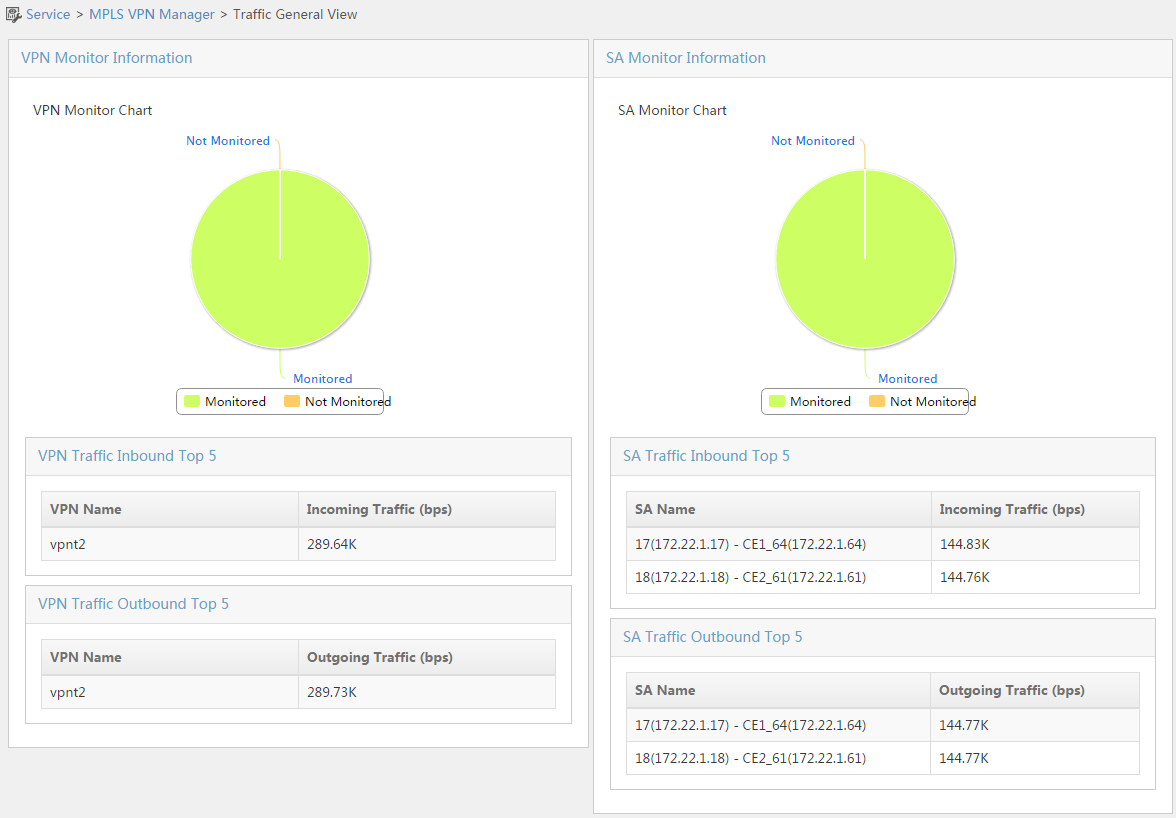
This page displays two kinds of monitoring information:
· VPN Monitor Information—MPLS VPN Management displays the number of monitored and unmonitored VPNs in a pie chart, and top 5 VPNs by inbound traffic and that by outbound traffic.
· SA Monitor Information—MPLS VPN Management displays the number of monitored and unmonitored SAs in a pie chart, and top 5 SAs by inbound traffic and that by outbound traffic.
Figure 14 Traffic monitor operation process
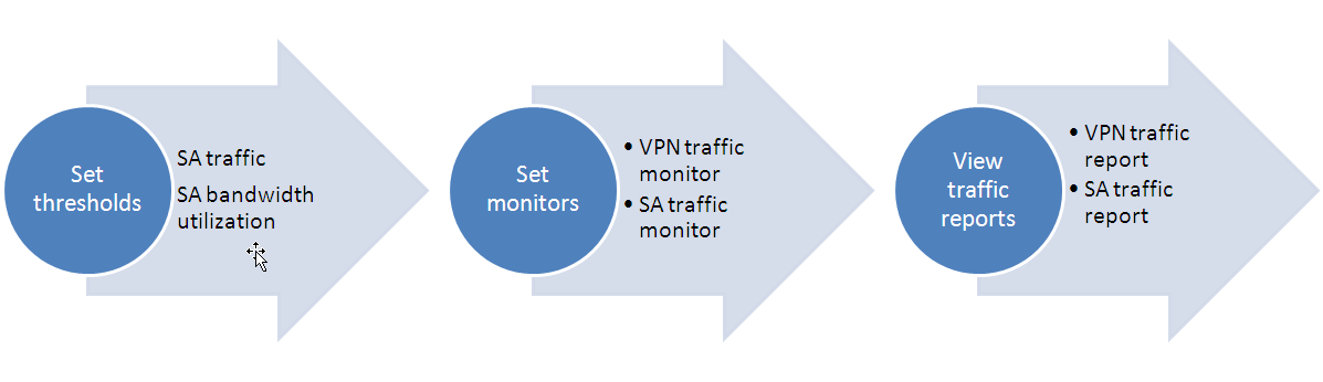
Setting thresholds
The system predefines four traffic alarm thresholds. They are thresholds of SA incoming traffic, SA outgoing traffic, SA incoming bandwidth utilization, and SA outgoing bandwidth utilization. You can modify but cannot add or delete the thresholds.
Viewing default threshold list
1. Click the Service tab.
2. From the navigation tree, select MPLS VPN Manager > Traffic Monitor > Threshold Setting.
The Threshold Setting page opens.
Default Threshold List contents
¡ Name—Name of the threshold.
¡ Level-1 Alarm Status—Whether the level-1 alarm for the threshold is Enabled or Disabled.
¡ Level-1 Alarm Threshold—If the level-1 alarm is enabled, this field displays the threshold. If the level-1 alarm is disabled, this field displays hyphens (--).
¡ Level-1 Alarm Severity—Options are Critical, Major, Minor, Warning, and Info.
¡ Level-2 Alarm Status—Whether the level-2 alarm for the threshold is Enabled or Disabled.
¡ Level-2 Alarm Threshold—If the level-2 alarm is enabled, this field displays the threshold. If the level-2 alarm is disabled, this field displays hyphens (--).
¡ Level-2 Alarm Severity—Options are Critical, Major, Minor, Warning, and Info.
¡ Modify—Click the Modify icon ![]() to display the
page for modifying the threshold.
to display the
page for modifying the threshold.
3. Click Refresh to view the latest Default Threshold List.
Modifying SA inbound/outbound traffic thresholds
1. Click the Service tab.
2. From the navigation tree, select MPLS VPN Manager > Traffic Monitor > Threshold Setting.
The Threshold Setting page opens.
3. Click the Modify icon ![]() for SA Incoming Traffic (bytes/s) or SA Outgoing Traffic
(bytes/s).
for SA Incoming Traffic (bytes/s) or SA Outgoing Traffic
(bytes/s).
The page for modifying the threshold opens.
4. Enable level-1 and level-2 alarms as needed. For each alarm, enter a value in bytes/s in the When the value is greater than field, and select an alarm severity from the list between Send and Alarm. Options for the alarm severity include Critical, Major, Minor, Warning, and Info.
The threshold value of level-2 alarm must be greater than that of level-1 alarm.
The severity level of level-2 alarm must be higher than that of level-1 alarm.
5. Click OK.
Modifying SA inbound/outbound bandwidth utilization thresholds
1. Click the Service tab.
2. From the navigation tree, select MPLS VPN Manager > Traffic Monitor > Threshold Setting.
The Threshold Setting page opens.
3. Click the Modify icon ![]() for SA Incoming Bandwidth Utilization (bytes/s). Alternatively, click the Modify icon
for SA Incoming Bandwidth Utilization (bytes/s). Alternatively, click the Modify icon ![]() for SA Outgoing Bandwidth Utilization (bytes/s).
for SA Outgoing Bandwidth Utilization (bytes/s).
The page for modifying the threshold opens.
4. Enable level-1 and level-2 alarms as needed. For each alarm, enter a value in % in the When the value is greater than field, and select an alarm severity from the list between Send and Alarm. Options for the alarm severity include Critical, Major, Minor, Warning, and Info.
The threshold value of level-2 alarm must be greater than that of level-1 alarm.
The severity level of level-2 alarm must be higher than that of level-1 alarm.
5. Click OK.
Setting VPN traffic monitor
Viewing VPN traffic monitor settings
1. Click the Service tab.
2. From the navigation tree, select MPLS VPN Manager > Traffic Monitor > VPN Traffic Monitor Setting.
The VPN List page opens.
¡ VPN Name—Name of the managed VPN.
¡ VPN Type—Type of the VPN. The value is BGP/MPLS VPN.
¡ Monitor Status—Monitor state of the VPN. Options are Monitored and Not Monitored.
¡ Monitored SA Ratio—Ratio of the monitored SAs to the total SAs in the VPN.
¡ Modify—Click the Modify icon ![]() to display the
VPN information page. You can view the SA information and alarm information in the
page.
to display the
VPN information page. You can view the SA information and alarm information in the
page.
Querying VPNs
1. Click the Service tab.
2. From the navigation tree, select MPLS VPN Manager > Traffic Monitor > VPN Traffic Monitor Setting.
The VPN List page opens.
3. Enter or select one or more of the following query criteria:
¡ VPN Name—Enter a VPN name. MPLS VPN Management supports fuzzy matching for this field.
¡ Monitor Status—Select a monitor state from the list. Options are All, Monitored, and Not Monitored.
4. Click Query.
The VPN List displays all VPNs matching the query criterion.
Adding monitor
1. Click the Service tab.
2. From the navigation tree, select MPLS VPN Manager > Traffic Monitor > VPN Traffic Monitor Setting.
The VPN List page opens.
3. Select one or more VPNs to be monitored.
4. Click Add Monitor.
Removing monitor
1. Click the Service tab.
2. From the navigation tree, select MPLS VPN Manager > Traffic Monitor > VPN Traffic Monitor Setting.
The VPN List page opens.
3. Select one or more VPNs and click Remove Monitor.
A confirmation dialog box opens.
4. Click OK.
Setting SA traffic monitor
Viewing SA traffic monitor settings
1. Click the Service tab.
2. From the navigation tree, select MPLS VPN Manager > Traffic Monitor > SA Traffic Monitor Setting.
The SA List page opens.
¡ SA Name—Name of the SA.
¡ Attached VPN—Name of the VPN to which the SA belongs.
¡ Monitor Status—Monitor state of the SA. Options are Monitored and Not Monitored.
¡ Attached PE—Name and IP address of the PE device to which the SA belongs.
¡ PE Interface—Description of the PE interface.
¡ Attached CE—Name and IP address of the CE device to which the SA belongs.
¡ CE Interface—Description of the CE interface.
Querying SAs
1. Click the Service tab.
2. From the navigation tree, select MPLS VPN Manager > Traffic Monitor > SA Traffic Monitor Setting.
The SA List page opens.
3. Enter or select one or more of the following query criteria:
¡ SA Name—Enter a SA name. MPLS VPN Management supports fuzzy matching for this field.
¡ Monitor Status—Select a monitor state from the list. Options are All, Monitored, and Not Monitored.
¡ Attached VPN—Enter the name of the VPN to which the SA belongs. MPLS VPN Management supports fuzzy matching for this field.
4. Click Query.
The SA List displays all SAs matching the query criterion.
Adding monitor
1. Click the Service tab.
2. From the navigation tree, select MPLS VPN Manager > Traffic Monitor > SA Traffic Monitor Setting.
The SA List page opens.
3. Select one or more SAs to be monitored.
4. Click Add Monitor.
Removing monitor
1. Click the Service tab.
2. From the navigation tree, select MPLS VPN Manager > Traffic Monitor > SA Traffic Monitor Setting.
The SA List page opens.
3. Select one or more SAs and click Remove Monitor.
A confirmation dialog box opens.
4. Click OK.
VPN traffic report
You can view the VPN traffic statistics in the VPN traffic report after VPN traffic monitor is enabled. The report shows the incoming traffic and outgoing traffic trends of a VPN.
Viewing VPN traffic list
1. Click the Service tab.
2. From the navigation tree, select MPLS VPN Manager > Traffic Monitor > VPN Traffic Report.
The VPN Traffic List page opens.
¡ VPN Name—Name of the monitored VPN.
¡ VPN Type—Type of the VPN. The value is BGP/MPLS VPN.
¡ Incoming Traffic (bytes/s)—Incoming traffic for the VPN.
¡ Outgoing Traffic (bytes/s)—Outgoing traffic for the VPN.
¡ View Details—Click the View icon ![]() to display the
VPN traffic report details page.
to display the
VPN traffic report details page.
Querying reports
1. Click the Service tab.
2. From the navigation tree, select MPLS VPN Manager > Traffic Monitor > VPN Traffic Report.
The VPN Traffic List page opens.
3. Enter a VPN name in the VPN Name field.
MPLS VPN Management supports fuzzy matching for this field.
4. Click Query.
The VPN Traffic List displays all VPNs matching the query criterion.
Viewing details
1. Click the View icon ![]() in the View Details
field for the VPN to be viewed.
in the View Details
field for the VPN to be viewed.
2. In the Query Condition area, select a time range from the Time Range list. Options are Data of last one hour (the default setting), Data of today, Data of this week, Data of this month, Data of this year, Customized data.
3. Click OK. The report is displayed below the Query Condition area.
¡ Graph type switch buttons
On the upper left of the graph are the Table, Line Chart, Bar Chart, and Sampling Point buttons. Click the buttons to view the report in different charts. The default setting is displaying data in a line chart.
¡ Export report links
Click Export as Excel on the upper right of the graph to export the report in the Excel format. You can also click Export as PDF, Export as HTML, or Export as TXT to export the report in the corresponding format. On the window that opens, click Traffic Report and select a save path. After the report is saved, click Close in the window to return to the Incoming Traffic graph.
¡ Incoming traffic graph
The x coordinate in the line chart represents the time and the y coordinate represents the traffic. The report shows the trend of the incoming traffic for the MPLS VPN.
¡ Incoming traffic list contents
- Monitored Object—Name of the VPN that is monitored.
- Min. Value—Minimum value of the monitored traffic.
- Max. Value—Maximum value of the monitored traffic.
- Current Value—Current value of the monitored traffic.
- Average Value—Average value of the monitored traffic.
- Min. Value at—Time when the minimum value of the monitored traffic appears.
- Max. Value at—Time when the maximum value of the monitored traffic appears.
- Valid Sampling Point—Number of the monitored valid sampling points.
The function and format of the outgoing traffic report are the same as those of the incoming traffic report. Details are not shown.
4. Click any option from the navigation tree to exit the page.
SA traffic report
You can view the SA traffic statistics in the SA traffic report after SA traffic monitor is enabled. The report shows the trends of the incoming traffic, outgoing traffic, incoming bandwidth utilization, and outgoing bandwidth utilization of an SA.
Viewing SA traffic list
1. Click the Service tab.
2. From the navigation tree, select MPLS VPN Manager > Traffic Monitor > SA Traffic Report.
The SA Traffic List page opens.
¡ SA Name—Name of the monitored SA.
¡ Attached VPN—Name of the VPN to which the SA belongs.
¡ Attached PE—Name and IP address of the PE device to which the SA belongs.
¡ PE Interface—Interface description of the PE.
¡ Attached CE—Name and IP address of the CE device to which the SA belongs.
¡ CE Interface—Interface description of the CE.
¡ Incoming Traffic (bytes/s)—Incoming traffic of the SA.
¡ Incoming bandwidth utilization (%)—Incoming bandwidth utilization of the SA.
¡ Outgoing Traffic (bytes/s)—Outgoing traffic of the SA.
¡ Outgoing bandwidth utilization (%)—Outgoing bandwidth utilization of the SA.
¡ View Details—Click the View icon ![]() to display the SA
traffic report details page.
to display the SA
traffic report details page.
Querying reports
1. Click the Service tab.
2. From the navigation tree, select MPLS VPN Manager > Traffic Monitor > SA Traffic Report.
The SA Traffic List page opens.
3. Enter a SA name in the SA Name field.
MPLS VPN Management supports fuzzy matching for this field.
4. Click Query.
The SA Traffic List displays all SAs matching the query criterion.
Viewing details
1. Click the View icon ![]() in the View Details
field for the SA to be viewed.
in the View Details
field for the SA to be viewed.
2. In the Query Condition area, select a time range from the Time Range list. Options are Data of last one hour (the default setting), Data of today, Data of this week, Data of this month, Data of this year, Customized data.
3. Click OK. The following reports are displayed below the Query Condition area: Incoming Traffic, Outgoing Traffic, Incoming bandwidth utilization, and Outgoing bandwidth utilization.
¡ Graph type switch buttons
On the upper left of the graph are the Table, Line Chart, Bar Chart, and Sampling Point buttons. Click the buttons to view the report in different charts. The default setting is displaying data in a line chart.
¡ Export report links
Click Export as Excel on the upper right of the graph to export the report in the Excel format. You can also click Export as PDF, Export as HTML, or Export as TXT to export the report in the corresponding format. On the window that opens, click the Traffic Report link and select a save path. After the report is saved, click Close in the window to return to the Incoming Traffic graph.
¡ Incoming traffic graph
The x coordinate in the line chart represents the time and the y coordinate represents the traffic. The report shows the change trend of the incoming traffic for the MPLS VPN.
¡ Incoming traffic list contents
- Monitored Object—Name of the VPN that is monitored.
- Min. Value—Minimum value of the monitored traffic.
- Max. Value—Maximum value of the monitored traffic.
- Current Value—Current value of the monitored traffic.
- Average Value—Average value of the monitored traffic.
- Min. Value at—Time when the minimum value of the monitored traffic appears.
- Max. Value at—Time when the maximum value of the monitored traffic appears.
- Valid Sampling Point—Number of the monitored valid sampling points.
- Times of Beyond Threshold Level 1—Number of times that the monitored traffic exceeds the level-1 threshold.
- Proportion of Beyond Threshold Level 1—Percentage of the sampling points that exceed the level-1 threshold to all sampling points.
- Times of Beyond Threshold Level 2—Number of times that the monitored traffic exceeds the level-2 threshold.
- Proportion of Beyond Threshold Level 2—Percentage of the sampling points that exceed the level-2 threshold to all sampling points.
The function and format of the outgoing traffic report are the same as those of the incoming traffic report. Details are not shown.
Incoming bandwidth utilization report
The graph type switch buttons and the export report links are the same as those of the incoming traffic report.
¡ Incoming bandwidth utilization graph
The x coordinate in the line chart represents the time and the y coordinate represents the bandwidth utilization. The report shows the trend of the incoming bandwidth utilization for the MPLS VPN.
¡ Incoming bandwidth utilization list contents
- Monitored Object—Name of the SA that is monitored.
- Min. Value—Minimum value of the bandwidth utilization.
- Max. Value—Maximum value of the bandwidth utilization.
- Current Value—Current value of the bandwidth utilization.
- Average Value—Average value of the bandwidth utilization.
- Min. Value at—Time when the minimum value of the bandwidth utilization appears.
- Max. Value at—Time when the maximum value of the bandwidth utilization appears.
- Valid Sampling Point—Number of the monitored valid sampling points.
- Times of Beyond Threshold Level 1—Number of times that the monitored traffic exceeds the level-1 threshold.
- Proportion of Beyond Threshold Level 1—Percentage of the sampling points that exceed the level-1 threshold to all sampling points.
- Times of Beyond Threshold Level 2—Number of times that the monitored traffic exceeds the level-2 threshold.
- Proportion of Beyond Threshold Level 2—Percentage of the sampling points that exceed the level-2 threshold to all sampling points.
The function and format of the outgoing bandwidth utilization report are the same as those of the incoming bandwidth utilization report. Details are not shown.
4. Click any option from the navigation tree to exit the page.
Applications
Managing carrier MPLS VPN
As shown in Figure 15, the provider uses MPLS VPN Management to manage full-mesh VPN 1. MPLS VPN Management accesses the network through a P device, and manages the PEs and P devices through public addresses. MPLS VPN Management does not manage the CEs, which are maintained by the customer.
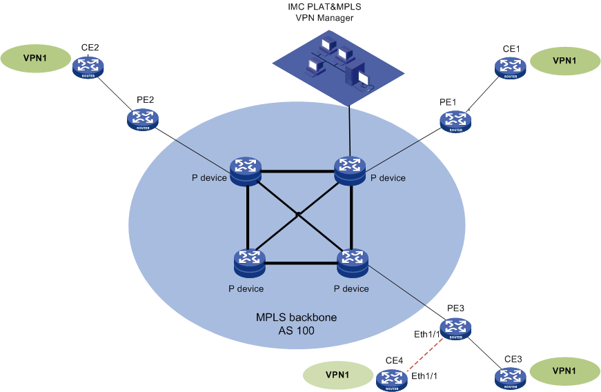
Perform the following tasks to manage VPN 1 with MPLS VPN Management:
1. Add VPN 1. See "Adding VPN 1."
2. Add a VCE. See "Adding a VCE."
3. Monitor and view the traffic of VPN 1 and the traffic between PE 1 and CE 1. See "Monitoring and viewing the traffic of VPN 1 and the traffic between PE 1 and CE 1."
Adding VPN 1
Use the auto-discovery function to add VPN 1 that has been deployed. After VPN 1 is discovered, create virtual CEs (VCEs) to represent the physical CEs.
Before you add VPN 1 to MPLS VPN Management, make sure BGP, MPLS, and SNMP have been configured on the devices, and the P devices and PEs have been added to IMC.
Creating AS 100
1. Click the Service tab.
2. From the navigation tree, select MPLS VPN Manager > VPN Resources > Region management.
The AS List page displays all ASs.
3. Click Add on top of the List area.
The Add AS dialog box opens.
4. Enter AS 100 in the AS Name field, and enter 100 in the AS Number field.
5. Click OK.
Importing PEs and P devices
1. Click the Service tab.
2. From the navigation tree, select MPLS VPN Manager > VPN Resources > Region management.
The AS List page displays all ASs.
3. Click the AS 100 link.
The Sub-region/PE Device List page opens.
4. Click Import PE on top of the Sub-region/PE Device List area.
The Import Device page opens.
5. Enable Filter devices according to AS number.
6. Click Select, and select PE 1, PE 2, and PE 3.
7. Click OK to return to the Sub-region/PE Device List page.
8. Click Import P on top of the Sub-region/PE Device List area.
The Import Device page opens.
9. Click Select and select the four P devices.
10. Click OK to return to the Sub-region/PE Device List page.
Discovering VPN 1 automatically
1. Click the Service tab.
2. From the navigation tree, select MPLS VPN Manager > Auto Discovery.
The auto discovery configuration guide page opens.
3. Select PEs:
a. In the Auto Discovery Parameter Settings area, enable Remove all invalid links and Synchronize PE device before auto discovery.
b. Click Select PE.
The Select Devices dialog box opens.
c. Select PE 1, PE 2, and PE 3, and click OK to return to the PE Selection page.
d. Click Auto Discovery.
4. A process bar for VPN auto discovery is displayed. When the loading is finished, the page for VPN selection opens.
5. Select the VPN:
a. Select VPN 1 in the VPN List Found.
b. Click Next.
6. To configure VRF binding relationships, enable Create Non-managed CE automatically and click OK.
You can see three links from the PEs to the corresponding VMCEs in the Configured VPN Link Result.
Verifying the configuration
1. From the navigation tree, select MPLS VPN Manager > VPN Resources > VPN management.
The BGP/MPLS VPN List page displays all VPNs.
You can view the VPN topology and the audit status for VPN 1 in the list.
2. From the navigation tree, select MPLS VPN Manager > VPN Resources > SA management.
The SA List page displays all SAs.
The PE1-VCE1, PE2-VCE2, and PE3-VMCE3 SAs are in the SA List.
Adding a VCE
Adding a new VCE
1. Click the Service tab.
2. From the navigation tree, select MPLS VPN Manager > VPN Resources > SA management.
The SA List page displays all SAs.
3. Click Add at the top of the SA list.
4. Select a PE and a VPN for the SA:
a. Click Select PE on the Select PE and VPN page.
The Select Devices page opens.
b. Select PE 3 and click OK to return to the Select PE and VPN page.
c. Click Select VPN on the Select PE and VPN page.
The Select VPN page opens.
d. Select VPN 1 and click OK to return to the Select PE and VPN page.
e. Click Next.
5. Select an SC:
a. Select SC(100:1) in the SC of Current VPN list.
b. Select the Add by HUB handling method.
c. Click Next.
6. Configure the PE and CE.
a. To configure the PE interface that connects to the CE, select Eth1/1 from the Interface Description list.
The interface IP address and subnet mask of Ethernet 1/1 automatically appear in the Interface IP/Mask field.
b. To configure the CE, enable Create Non-managed CE automatically, and then click Next.
7. Configure the VRF information.
The system automatically generates a default VRF name in the VRF Name field.
The system automatically generates a default RD value in the RD Value field.
Click Next.
8. The Summary page includes the Basic Information, Configuration command, and Deploy Immediately areas. The Basic Information and Configuration command areas help you verify the configuration before you execute the configuration commands.
a. Enable Deploy Immediately.
b. Click OK to return to the SA List page.
Verifying the configuration
From the navigation tree, select MPLS VPN Manager > VPN Resources > SA management.
The SA List page displays all SAs.
You can see the link deployment status for the newly added SA is Deploying. After the SA is deployed, the status changes to Normal. You can view the PE3-VCE4 SA in the topology for VPN 1.
Monitoring and viewing the traffic of VPN 1 and the traffic between PE 1 and CE 1
Adding VPN 1 to be monitored
1. Click the Service tab.
2. From the navigation tree, select MPLS VPN Manager > Traffic Monitor > VPN Traffic Monitor Setting.
The VPN List page opens.
3. Select VPN1 in the list and click Add Monitor.
Viewing the VPN traffic report
1. Click the Service tab.
2. From the navigation tree, select MPLS VPN Manager > Traffic Monitor > VPN Traffic Report.
The VPN Traffic List page opens.
3. Click the View icon ![]() in the View Details
field for VPN 1.
in the View Details
field for VPN 1.
The report page opens.
4. In the Query Condition area, select a time range from the Time Range list.
Options are Data of last one hour (the default setting), Data of today, Data of this week, Data of this month, Data of this year, and Customized data.
5. Click OK.
The report data is displayed below the Query Condition area.
Adding the PE1-VCE1 SA to be monitored
1. Click the Service tab.
2. From the navigation tree, select MPLS VPN Manager > Traffic Monitor > SA Traffic Monitor Setting.
The SA List page opens.
3. Select PE1-VCE1 in the list and click Add Monitor.
Viewing the SA traffic report
1. Click the Service tab.
2. From the navigation tree, select MPLS VPN Manager > Traffic Monitor > SA Traffic Report.
The SA Traffic List page opens.
3. Click the View icon ![]() in the View Details
field for the PE1-VCE1 SA.
in the View Details
field for the PE1-VCE1 SA.
The report page opens.
4. In the Query Condition area, select a time range from the Time Range list.
Options are Data of last one hour (the default setting), Data of today, Data of this week, Data of this month, Data of this year, and Customized data.
5. Click OK.
The report data is displayed below the Query Condition area.
Managing enterprise's MPLS VPN
As shown in Figure 16, the enterprise uses MPLS VPN Management to manage its own MPLS VPNs. MPLS VPN Management accesses the network through a management CE, manages the P and PE devices through public addresses, and manages the CEs through the management VPN.
Fully meshed VPN 1 and VPN 2 carry VPN traffic. The hub-spoke management VPN carries management traffic between MPLS VPN Management and devices, and isolates sites at Layer 3. On the management PE (hub of the management VPN), configure the import RT value as 200:1 and the export RT value as 200:2. On each PE, configure a service VPN and a management VPN. On each spoke of the management VPN, configure the import RT value as 200:2 and the export RT value as 200:1.
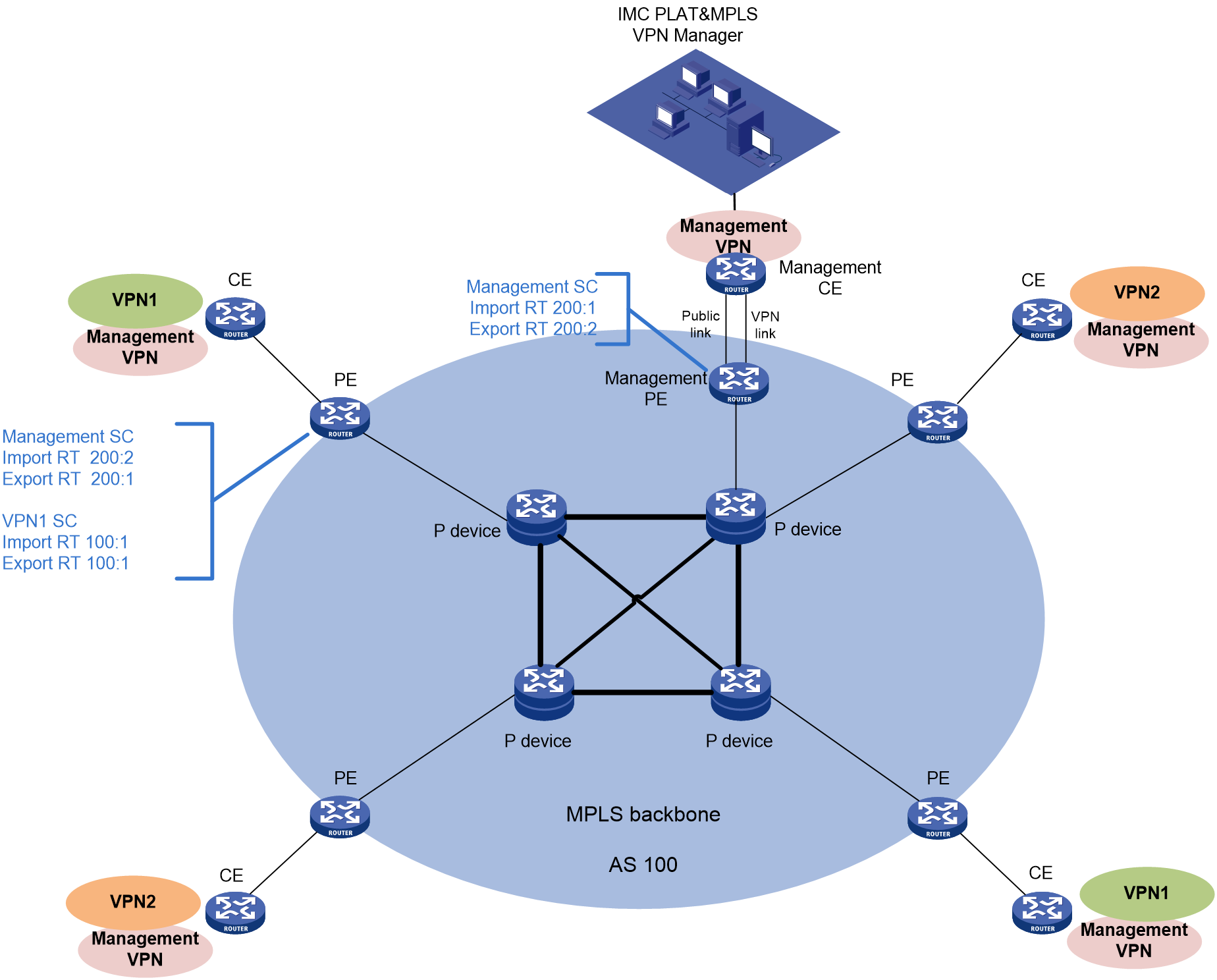
Perform the following tasks to manage enterprise MPLS VPNs with MPLS VPN Management:
1. Configure the management VPN. See "Configuring the management VPN."
2. Add VPN 2. See "Adding VPN 2."
3. Troubleshoot. See "Troubleshooting."
Configuring the management VPN
Assume that the management VPN has been deployed on the network.
To configure the management VPN:
1. Click the Service tab.
2. From the navigation tree, select MPLS VPN Manager > VPN Resources > Mgt. VPN Configuration.
The Mgt. VPN Configuration page opens.
3. Configure the following parameters:
¡ Status—Select Enabled from the list.
¡ HUB's Import RT—Enter 200:1.
¡ HUB's Export RT—Enter 200:2.
4. Click OK.
Adding VPN 2
Adding AS 100
1. Click the Service tab.
2. From the navigation tree, select MPLS VPN Manager > VPN Resources > Region management.
The AS List page displays all ASs.
3. Click Add at the top of the AS list.
The Add AS dialog box opens.
4. Enter AS 100 in the AS Name field and enter 100 in the AS Number field.
5. Click OK.
Importing PEs and P devices
1. Click the Service tab.
2. From the navigation tree, select MPLS VPN Manager > VPN Resources > Region management.
The AS List page displays all ASs.
3. Click AS 100.
The Sub-region/PE Device List page opens.
4. Click Import PE on top of the Sub-region/PE Device List area.
The Import Device page opens.
5. Enable Filter devices according to AS number.
6. Click Select and select PE 1, PE 2, PE 3, and PE 4.
7. Click OK to return to the Sub-region/PE Device List page.
8. Click Import P on top of the Sub-region/PE Device List area.
The Import Device page opens.
9. Click Select and select the four P devices.
10. Click OK to return to the Sub-region/PE Device List page.
Importing CEs
1. Click the Service tab.
2. From the navigation tree, select MPLS VPN Manager > VPN Devices > CE Device List.
The CE Device List page displays all CE devices.
3. Click Import on top of the CE Device List area.
The Import Device page opens.
4. Click Select and select CE 1, CE 2, CE 3, and CE 4.
5. Click OK to return to the Import Device page.
6. Click OK.
The page for import progress opens. You can view the import process and result.
Adding VPN 2
1. Click the Service tab.
2. From the navigation tree, select MPLS VPN Manager > VPN Resources > VPN management.
The BGP/MPLS VPN List page displays all VPNs.
3. Click Add on top of the BGP/MPLS VPN List area.
The Add VPN dialog box opens.
4. Configure the following parameters:
¡ VPN Name—Enter VPN2.
¡ Connectivity Audit—Enable Periodical audit, use the default audit interval (8 hours), and enable Audit Inter-Spoke Unconnectivity.
¡ Description—Enter Add VPN2 as needed.
5. Click OK.
Adding an SC
1. Click the Service tab.
2. From the navigation tree, select MPLS VPN Manager > VPN Resources > VPN management.
The BGP/MPLS VPN List page displays all VPNs.
3. Click the VPN2 link to display the VPN details page.
4. Click the SC List tab on the page.
5. Click Add.
6. Configure the following parameters:
¡ VPN Name—Enter SC(300:1, 300:1).
¡ SC Networking Type—Select Full-Mesh.
¡ HUB's Import RT—Enter 300:1.
¡ HUB's Export RT—Enter 300:1.
7. Click OK.
Adding the PE2-CE2 SA
1. Click the SA List tab on the VPN details page.
2. Click Add at the top of the SA list.
3. Select a PE and a VPN for the SA:
a. Click Select PE on the Select PE and VPN page.
The Select Devices page opens.
b. Select PE2 and click OK to return to Select PE and VPN page.
c. Click Select VPN.
The Select VPN page opens.
d. Select VPN2 and click OK to return to Select PE and VPN page.
e. Click Next.
4. Select an SC for the SA:
a. Select SC(300:1, 300:1) in the SC of Current VPN list.
b. Select Add by HUB.
c. Click Next.
5. Configure the interfaces on the PE and the CE.
To configure the PE 2 interface that connects to the CE:
a. Select Eth1/1 from the Interface Description list.
b. The IP address and subnet mask for the interface automatically appear in the Interface IP/Mask field.
To configure the CE 2 interface that connects to the PE:
a. Select CE2 from the Device Name list.
b. Select Eth1/1 from the Interface Description list.
The IP address and subnet mask for the interface automatically appear in the Interface IP/Mask field.
c. Click Next.
6. Configure the VRF information.
The system automatically generates a default VRF name in the VRF Name field.
The system automatically generates a default RD value in the RD Value field.
a. Enable Configure Route.
b. Click Next.
7. Configure routing between PE 2 and CE 2:
a. Select the OSPF routing protocol.
b. Click Next.
8. The Summary page includes the Basic Information, Configuration command, and Deploy Immediately areas. The Basic Information and Configuration command areas help you verify the configuration before you execute the configuration commands.
a. Disable Deploy Immediately. After you add the PE4-CE4 SA, deploy the PE2-CE2 SA and the PE4-CE4 SA together.
b. Click OK to return to the SA List page.
Add the PE4-CE4 SA in the same way that the PE2-CE2 SA is added.
Deploying SAs
1. Click the SA List tab on the VPN details page.
2. Select the PE2-CE2 SA and the PE4-CE4 SA in the list.
3. Click Deploy on top of the SA List area.
Verifying the configuration
After the deployment, the link status for the two SAs is Normal, which indicates that CE 2 and CE 4 can communicate with each other.
Troubleshooting
1. Click the Service tab.
2. From the navigation tree, select MPLS VPN Manager > VPN Resources > VPN management.
The BGP/MPLS VPN List page displays all VPNs.
3. Click the link in the Audit Result field for VPN1, whose Audit Status is Disconnected.
The page for connectivity audit opens.
4. Click the Troubleshooting
icon ![]() for the failed link in the VPN Link Audit
Information list.
for the failed link in the VPN Link Audit
Information list.
5. The Troubleshooting List displays the operation and result for troubleshooting.
Troubleshooting List contents
¡ Time—Time when the troubleshooting began, in seconds.
¡ Source—Source device.
¡ Destination—Destination device.
¡ Result—Result, which helps you fix the network problems.
Using L2VPN Management
L2VPN Management allows for building and managing VPLS, VLL, and PBB Layer 2 VPNs. L2VPN Management supports both LDP and BGP signaling for VPLS VPN, supports LDP signaling for VLL VPN, and supports PBB + VPLS VPN.
L2VPN Management brings the following benefits:
· Simplified VPN deployment—L2VPN Management provides wizards for deploying VPLS, VLL, and PBB Layer 2 VPNs, simplifying your configurations.
· Auto discovery—L2VPN Management can automatically discover existing VPNs and add the VPNs into IMC. You can add/delete PEs and ACs for the discovered VPNs.
· VPN monitoring—L2VPN Management provides alarms, audit state, and configuration information. The alarms help you troubleshoot device problems. The audit state information shows the connectivity of VPN links. An audit operation can be performed one time or periodically. The configuration information shows detailed VPN settings, including the VSI ID, I-SID, PW ID, VPN type, and B-VLAN.
· VPN topology—L2VPN Management shows a topology for each VPN where you can perform operations such as viewing VPN information, ACs, and PWs, deploying and undeploying VPNs, and auditing connectivity for a whole VPN.
Basic VPN concepts
VPLS overview
Virtual Private LAN Service (VPLS), also called Transparent LAN Service (TLS) or Virtual Private Switched Network Service, can deliver a point-to-multipoint Layer 2 VPN (L2VPN) service over public networks. With VPLS, geographically-dispersed sites can interconnect and communicate over metropolitan area network (MAN) or wide area network (WAN) as if they were on the same Local Area Network (LAN). Service providers can create on the PEs a series of virtual switches for customers, allowing customers to build their LANs across the MAN or WAN.
Basic concepts of VPLS
· CE (Customer Edge)—Customer edge device that is directly connected with the service provider network.
· PE (Provider Edge)—Provider edge device that connects one or more CEs to the service provider network, mainly for access to VPN services.
· VSI (Virtual Switch Instance)—Virtual switch instance that maps actual VPLS access links to virtual links.
· PW (Pseudo Wire)—A pseudo wire is the bidirectional virtual connection between two VSIs. A pseudo wire consists of two unidirectional virtual circuits (VCs).
· AC (Attachment Circuit)—Attachment circuit that connects a CE to a PE. It can use physical interfaces or virtual interfaces.
· Tunnel—A tunnel, usually an MPLS tunnel, used to carry one or more PWs. It is a direct channel between a local PE and the peer PE for transparent transmission in-between.
A typical H-VPLS network involves the following basic concepts:
· UPE (User Facing-Provider Edge)—User facing provider edge device that functions as the user access convergence device.
· NPE (Network Provider Edge)—Network provider edge device that functions as the network core PE. An NPE resides at the edge of a VPLS network core domain and provides transparent VPLS transport services between core networks.
· U-PW—PW link between a UPE and an NPE.
· N-PW—PW link between two NPEs.
VPLS VPN types
· LDP VPN—Uses the Label Distribution Protocol (LDP) to establish virtual circuits by establishing point-to-point sessions between a pair of PEs.
· BGP VPN—Uses the Border Gateway Protocol (BGP) to establish signaling sessions through route reflectors (RRs) and supports networking across ASs.
Operation of VPLS
VPLS operation includes these elements:
· L2-pdu—Data link layer packet.
· Dmac—MAC address of the next hop device.
· Smac—MAC address of the local device.
· L—Public network label.
· V—Private network label.
· L'—Public network label after the packet is forwarded along the LSP.
Data forwarding procedure:
1. A PE receives a data packet from a CE through the AC. According to the VSI, the PE pushes its own MAC address, the MAC address of the next hop, the public network label, and the private network label into the packet. Then the PE forwards the packet to the core network according to the address of the next hop.
2. After receiving the packet, the core network encapsulates the packet with the new public network label and the MAC address of the new next hop device, and then forwards the packet to the specified PE accordingly.
3. The PE sends the packet to the right CE through the AC according to the private network label.
VLL overview
VLL (Virtual Leased Line): VLL provides point-to-point L2VPN services over the public network. With VLL, two sites can communicate as if they were directly connected. VLL is a form of MPLS L2VPN. It uses inner labels to identify virtual lines (Layer 2 tunnels), hereinafter referred to as virtual circuits (VCs), and uses outer labels to identify public tunnels. The network devices of the service provider do not need to maintain any Layer 2 information but perform MPLS forwarding on the public networks based on MPLS labels. In VLL, a Forwarding Equivalence Class (FEC) is about the VC identifier and some Layer 2 information.
Basic concepts of VLL
With the existing technologies, VLL can be implemented mainly in two methods, which use different signaling protocols to exchange VC information. One method is called Martini (the L2VPN Management only support this method). The Martini method uses a standard two-layer label stack. The inner labels (VC labels) are exchanged through the extended LDP. The Martini draft extends the standard LDP, adding a new FEC type, the VC FEC, for exchanging VC labels. A VC FEC identifies a VC by VC Type and VC ID. VC Type indicates the link layer encapsulation type and VC ID uniquely identifies a VC of the same type on a PE. The PEs that connect two CEs switch VC labels through LDP and bind the corresponding CEs by the VC ID. A VC between the two CEs are then established and the two CEs can transport Layer 2 data over the VC. The Martini method does not provide the local switching function. Outer labels is used to transport VC data over the service provider network. Because PEs can identify data of different VCs by inner label, multiple VCs can share the public tunnel.
PBB overview
PBB meets the Metro Ethernet Network (MEN) requirements. In the MEN service hierarchy model, PBB is at the carrier level, used to establish MAC tunnels to separate services of different customers on the backbone. A network employing 802.1ah is called a Provider Backbone Bridge Network (PBBN).
Basic concepts of PBB
In a typical PBBN, the two types of devices are:
· BEB (Backbone Edge Bridge)—Like a PE in an MPLS network. It performs MAC-in-MAC encapsulation for the incoming packets and then delivers the encapsulated packets to subsequent devices, which forwards the packets according to the B-MAC and B-VID. It also de-encapsulates the received MAC-in-MAC packets to standard Ethernet packets and then looks up the forwarding table and sends the packets from the corresponding outgoing interfaces.
· BCB (Backbone Core Bridge)—Like a P device in an MPLS network. It forwards the received MAC-in-MAC packets according to the outer B-MAC and B-VID. A BCB only performs packet bridging, learning the MAC addresses on the backbone. It does not need to learn the huge number of MAC addresses in the customer networks. This reduces the network deployment expenses and provides better expansibility for the PBBN.
Terminology
This section clarifies some VPN operations and concepts.
· Layer VPN—L2VPN Management provides basic and detailed information for a Layer VPN. Basic information includes the VPN name, contact, description, and audit interval. Detailed information includes PEs, ACs, alarms, and audit information besides basic information.
· Add and Deploy—An Add operation adds a configuration task on L2VPN Management but it does not deploy the configuration task to devices. Therefore, an Add operation does not change the network. You can view and modify added configuration tasks only on L2VPN Management. A Deploy operation deploys a configuration task to devices and thus changes the network. You can also add and then deploy a configuration task.
· Delete and Undeploy—A Delete operation deletes the selected configuration from L2VPN Management but not from the network. For example, after you delete a VPN, the VPN still exists on the network. You can re-add this VPN to L2VPN Management through auto discovery. An Undeploy operation deletes the selected configuration from the network. For example, after you undeploy a VPN, the VPN is removed from the network, and you cannot re-add this VPN to L2VPN Management through auto discovery.
· Modify—A Modify operation can only change information configured on L2VPN Management, such as the VPN name, contact, description, audit interval, VCE label, and VCE MAC address. It cannot change information on physical CEs. L2VPN Management can only read information from physical CEs.
Using L2VPN Management with non-BGP protocols
This section provides a quick start for deploying and managing L2VPNs using non-BGP protocols, including LDP VPLS, VLL, PBB.
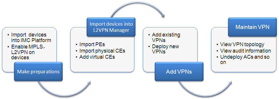
As shown in Figure 17, the quick start includes the following steps.
1. Make preparations:
¡ Import PE, BEB, and CE devices into IMC Platform, and configure correct SNMP parameters for the devices and IMC Platform. For details, see H3C Intelligent Management Center v7.3 Enterprise and Standard Platform Administrator Guide.
¡ To build VPLS or VLL VPNs, you must enable MPLS, L2VPN, and MPLS L2VPN on PEs. To build PBB VPNs, you must enable L2VPN on BEBs. For details, see the corresponding configuration guides and command references.
2. Import devices into L2VPN Management:
¡ For VPLS and VLL VPNs, import PEs. For PBB VPNs, import BEBs. For details, see Importing PE devices.
¡ Import physical CEs. For details, see "Importing CE devices."
¡ Import virtual CEs (VCEs). For details, see "Adding/Modifying a VCE."
3. Add VPNs:
¡ Add existing VPNs to L2VPN Management through auto discovery. For details, see "Adding a VPN " or "Automatic discovery."
¡ Deploy new VPNs. For details, see "Deploying VPNs."
4. Maintain VPNs
You can view VPN topology, alarms, and audit information, and modify or undeploy ACs, PWs, PEs, and CEs.
The following content will introduce how to use L2VPN Management deployed non-BGP protocol.
Managing VPN resources
VPN resources include VPNs services and Attachment Circuit (ACs). A VPN service is a Layer 2 VPN. An AC is a link that connects a PE to a CE. L2VPN Management provides a VPN list and an AC list for you to manage all VPNs and ACs.
Managing VPNs
The VPN list shows all VPN services, including VPLS, VLL, PBB, and VPLS+PBB VPN services. You can add, modify, delete, and audit VPN services from the VPN list.
Viewing the VPN list
1. Click the Service tab.
2. From the navigation tree, select L2VPN Manager > VPN Resources > VPN List.
¡ Status—State of the VPN. Options are Critical, Major, Minor, Warning, Normal, Unknown, and Unmanaged.
¡ VSI Admin Status—State of the VSI. Options are Enabled and Disabled.
¡ VPN name—Name of the VPN. You can click a VPN name to view details about that VPN.
¡ VSI ID—VSI ID for a VLL or VPLS VPN.
¡ I-SID—I-SID for a PBB VPN.
¡ PW ID—PW ID for a VLL or VPLS VPN.
¡ VPN Type—VPN type. Options are VPLS, VLL, PBB, and VPLS+PBB.
¡ B-VLAN—B-VLAN for a PBB or VPLS+PBB VPN.
¡ Topology—Provides a Topology link for you to view L2VPN topology.
¡ Audit Time—Time when the last VPN connectivity audit was performed, in the format YYYY-MM-DD hh:mm:ss.
¡ Audit Result—Result of the last VPN connectivity audit. Options are Unaudited, Normal, Auditing, Unknown, Unconnected, and Error. If the result is Unconnected, you can click the Unconnected link to view the cause.
¡ Modify—Provides a Modify icon ![]() for
you to modify basic settings for a VPN.
for
you to modify basic settings for a VPN.
3. Click Refresh to view the latest VPN list.
Querying a VPN
1. Click the Service tab.
2. From the navigation tree, select L2VPN Manager > VPN Resources > VPN List.
3. Enter or select one or more of the following query criteria:
¡ VPN name—Enter the name of a VPN. This field supports fuzzy matching.
¡ I-SID—Enter the I-SID of a PBB VPN. This field supports fuzzy matching.
¡ VPN Type—Select a VPN type. Options are All, VPLS, VLL, PBB, and VPLS+PBB.
¡ Audit Result—Select an audit result. Options are All, Unaudited, Normal, Auditing, Unknown, Unconnected, and Error.
¡ VSI ID—Enter the VSI ID of a VLL or VPLS VPN. This field supports fuzzy matching.
¡ PW ID—Enter the PW ID of a VPN. This field supports fuzzy matching.
¡ VPN Status—Select a VPN state. Options are All, Critical, Major, Minor, Warning, Normal, Unknown, and Unmanaged.
¡ VSI Admin Status—Select a VSI state. Options are All, Enabled, and Disabled.
4. Click Query.
The VPN list displays all the matching VPNs. To clear the query results, click Reset.
Adding a VPN
This function supports adding VPLS, VLL, and PBB VPNs.
1. Click the Service tab.
2. From the navigation tree, select L2VPN Manager > VPN Resources > VPN List.
3. Click Add.
4. Click one of the following options.
¡ Deploy VPLS VPN. For information about deploying a VPLS VPN, see "Deploying a VPLS VPN."
¡ Deploy VLL VPN. For information about deploying a VLL VPN, see "Deploying a VLL VPN."
¡ Deploy PBB VPN. For information about deploying a PBB VPN, see "Deploying a PBB VPN."
Modifying basic VPN settings
L2VPN Management provides basic and advanced VPN settings. Basic settings include the VPN name, contact, description, and audit interval. Advanced settings include information about PEs, ACs, VLAN mappings, and alarms.
1. Click the Service tab.
2. From the navigation tree, select L2VPN Manager > VPN Resources > VPN List.
3. Click the Modify icon ![]() of
the target VPN.
of
the target VPN.
4. Modify the following settings:
¡ VPN Name—Enter a new VPN name.
¡ Contact—Enter a new contact.
¡ Description—Enter a new description.
¡ Audit Interval (in hours)—Enter a new audit interval in the range of 0 to 24. An audit interval of 0 disables audit function.
5. Click OK.
Undeploying VPNs
You can undeploy an entire VPN or some devices and links in a VPN.
1. Click the Service tab.
2. From the navigation tree, select L2VPN Manager > VPN Resources > VPN List.
3. Select one or more VPNs from the VPN list.
4. Click More Operations.
5. Select Undeployment.
For more information, see "Undeploying VPNs."
Enabling VSIs
1. Click the Service tab.
2. From the navigation tree, select L2VPN Manager > VPN Resources > VPN List.
3. Select one or more VPNs from the VPN list.
4. Click More Operations….
5. Select Enable VSI.
6. Click OK in the window that opens.
Deleting VPNs
This task deletes VPNs from L2VPN Management but the deleted VPNs still exist in the network. You can perform VPN auto-discovery to add the deleted VPNs to L2VPN Management. To delete a VPN from the network, you must undeploy the VPN.
1. Click the Service tab.
2. From the navigation tree, select L2VPN Manager > VPN Resources > VPN List.
3. Select one or more VPNs from the VPN list.
4. Click Delete.
5. Click OK in the window that opens.
Auditing VPNs
1. Click the Service tab.
2. From the navigation tree, select L2VPN Manager > VPN Resources > VPN List.
3. Select one or more VPNs from the VPN list.
4. Click Audit.
5. After a while, click Refresh to view the audit result.
Managing ACs
The AC list shows all ACs. You can view, query, and delete ACs from the AC list.
Viewing the AC list
1. Click the Service tab.
2. From the navigation tree, select L2VPN Manager > VPN Resources > AC List.
¡ PE Name—Name of the PE. You can click a PE name to view details about that PE.
¡ PE Interface Description—Displays the PE's interface connected to the CE.
¡ CE Name—Name of the CE. You can click a CE name to view details about that CE.
¡ Attached VPN—VPN to which the AC belongs.
¡ Detail—Provides a Detail icon ![]() for you to view
details about the AC.
for you to view
details about the AC.
3. Click Refresh to view the latest AC list.
Querying ACs
1. Click the Service tab.
2. From the navigation tree, select L2VPN Manager > VPN Resources > AC List.
3. Enter or select the following query criteria:
¡ PE Name—Enter a PE name. This field supports fuzzy matching.
¡ Attached VPN—Enter a VPN name. This field supports fuzzy matching.
¡ CE Name—Enter a CE name. This field supports fuzzy matching.
4. Click Query.
The VPN list displays all the matching ACs. To clear the query results, click Reset.
Deleting ACs
This task deletes ACs from L2VPN Management but the deleted ACs still exist in the network.
1. Click the Service tab.
2. From the navigation tree, select L2VPN Manager > VPN Resources > AC List.
3. Select ACs from the AC list.
4. Click Delete.
5. Click OK in the window that opens.
Deploying VPNs
The section describes tasks for deploying and undeploying LDP-based VPLS and VLL VPNs and PBB VPNs. You can create and deploy a VPN by following the deployment wizard, and view the deployment results.
Deploying a VPLS VPN
You can deploy a new VPLS VPN or deploy new ACs or PWs for an existing VPLS VPN. Hierarchical VPLS is supported.
1. Click the Service tab.
2. From the navigation tree, select L2VPN Manager > VPN Deployment > Deploy VPLSs.
Figure 18 shows the wizards for deploying a VPLS VPN and a Hierarchical VPLS VPN.
Figure 18 Wizards for deploying VPLS VPN and Hierarchical VPLS VPN
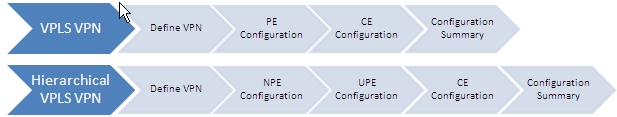
3. Complete the configurations in the wizards.
The following sections describe these configurations.
Defining VPN
1. Configure the following settings:
¡ PE Type—Select PE or Hierarchical PE. To configure a PE, see "Configuring PEs." To configure a hierarchical PE, see "Configuring NPEs."
¡ VPN Operation Type—Select Add VPN or Select VPN. If you select Select VPN, you must enter the name of an existing VPN. The system automatically fills in the VSI ID, PW Transport Mode, and Audit Interval, which cannot be modified.
¡ VPN Name—Enter a name for the VPN.
¡ VSI ID—Enter a VSI ID or use the default VSI ID.
¡ PW Transport Mode—Select VLAN or Ethernet.
¡ Audit Interval (in hours)—Enter an audit interval, which is an integer in the range of 0 to 24, or use the default audit interval. A value of 0 disables audit.
¡ Description—Enter a description for the VPN.
¡ Contact—Enter a contact. The default contact is the current operator.
Configuring PEs
1. Add ACs:
a. Click Add under AC List.
b. Select the PE interface that connects to the CE, and click OK.
If the selected interface is a Layer 3 interface, perform step c. If the selected interface is a Layer 2 interface, perform step d.
c. Under Config UNI Interface, select an access type.
d. Under Config UNI Interface, enter the service instance, bandwidth, encapsulation VLAN, and select the encapsulation type and access type.
e. Click OK.
f. Repeat the preceding steps to add more ACs.
2. Add PEs:
A PE that is configured when you add an AC is automatically added to the PE Device List. You can also manually add a PE as follows:
a. Click Add under PE Device List.
b. Select one or more PEs and click OK.
3. Select a tunnel policy for each PW in the PW List.
Tunnel policies include default, use GRE tunnel first, and create and use GRE tunnel.
4. Configure VLAN mappings:
The Configure VLAN Mapping option exists if you selected a physical CE when you added an AC. It does not exist if you selected only VCEs.
5. Click Next.
The CE Configuration page opens if you selected the Configure VLAN Mapping option, or the Configuration Summary page opens if you did not select the Configure VLAN Mapping option.
Configuring NPEs
1. Add ACs:
a. Click Add under AC List.
b. Select the NPE interface that connects to the CE, and click OK.
If the selected interface is a Layer 3 interface, perform step c. If the selected interface is a Layer 2 interface, perform step d.
c. Under Config UNI Interface, select an access type.
d. Under Config UNI Interface, enter the service instance, bandwidth, encapsulation VLAN, and select the encapsulation type and access type.
e. Click OK.
f. Repeat the preceding steps to add more ACs.
2. Add NPEs:
An NPE that is configured when you add an AC is automatically added to the NPE Device List. You can also manually add an NPE as follows:
a. Click Add under NPE Device List.
b. Select one or more NPEs and click OK.
3. Click Next to display the UPE Configuration page.
Configuring UPEs
1. Add ACs:
a. Click Add under AC List.
b. Select the PE interface that connects to the CE, and click OK.
If the selected interface is a Layer 3 interface, perform step c. If the selected interface is a Layer 2 interface, perform step d.
c. Under Config UNI Interface, select an access type.
d. Under Config UNI Interface, enter the service instance, bandwidth, encapsulation VLAN, and select the encapsulation type and access type.
e. Click OK.
f. Repeat the preceding steps to add more ACs.
2. Add UPEs:
A UPE configured when you add an AC is automatically added to the UPE Device List. You can also manually add a UPE as follows:
a. Click Add under UPE Device List.
b. Select one or more UPEs and click OK.
3. Specify the main/backup NPE for UPEs:
a. Select one or more UPEs from the UPE Device List, and click Main NPE or Backup NPE.
b. Select an NPE in the window that opens.
c. Click OK.
4. Select a tunnel policy for each PW from the Tunnel Policy column in the PW List.
Tunnel policies include default, user GRE tunnel first, and create and use GRE tunnel.
5. Configure VLAN mappings:
The Configure VLAN Mapping option exists if you selected a physical CE when you added an AC. It does not exist if you selected only VCEs.
6. Click Next.
The CE Configuration page opens if you selected the Configure VLAN Mapping option, or the Configuration Summary page opens if you did not select the Configure VLAN Mapping option.
Configuring CEs
1. Click Add under VLAN Mapping List, and configure the following settings in the window that opens:
¡ Device Label—Select a device label.
¡ Interface Description—Enter a description for the interface.
¡ VLAN Mappings—Enter a CVLAN-SVLAN mapping.
2. Click OK.
You can repeat the preceding steps to add more VLAN mappings.
3. Click Next to display the Configuration Summary page.
Deploying the VPLS VPN
1. Verify the VPN, PE, and CE settings in the Configuration Summary page.
2. Select Deploy Immediately.
3. Click OK to view the deployment result.
IMC deploys your settings to devices. If you did not select Deploy Immediately, IMC only generates VPLS VPN information and commands, but does not deploy the settings to devices.
Deploying a VLL VPN
1. Click the Service tab.
2. From the navigation tree, select L2VPN Manager > VPN Deployment > Deploy VLLs.
3. Complete the configurations in the Define VPN, Local PE Configuration, Remote PE Configuration, and Configuration Summary pages.
The following sections describe these configurations.
Defining VPN
1. Configure the following settings:
¡ VPN Name—Enter a name for the VPN.
¡ PW ID—Enter a PW ID or use the default PW ID.
¡ PW Transport Mode—Select VLAN or Ethernet.
¡ Tunnel Policy—Select a tunnel policy. Options are default, use GRE tunnel first, and create and use GRE tunnel.
¡ Audit Interval (in hours)—Enter an audit interval, which is an integer in the range of 0 to 24, or use the default audit interval. A value of 0 disables audit.
¡ Description—Enter a description for the VPN.
¡ Contact—Enter a contact. The default contact is the current operator.
2. Click Next to display the Local PE Configuration page.
Configuring the local PE
1. Configure the following settings:
¡ UNI Interface—Click Select and select the PE' interface that connects to the local CE.
If the selected interface is a Layer 3 interface, click OK and select a CE. If the selected interface is a Layer 2 interface, click OK and complete the following settings:
¡ Service Instance—Enter the ID of the service instance.
¡ Bandwidth (Mbps)—Enter the maximum bandwidth for the AC.
¡ Encap Type—Select an encapsulation type. Options are S-VID, S-VID Only Tagged, Port-based, Tagged, and Untagged.
¡ Encapsulation VLAN—Enter a VLAN ID or VLAN ID range.
¡ Access Type—Select VLAN or Ethernet.
¡ CE Device—Click Select and select a CE or VCE. A VCE is selected by default.
2. Click Next to display the Remote PE Configuration page
Configuring the remote PE
1. Configure the following settings:
¡ UNI Interface—Click Select and select the remote PE' interface that connects to the remote CE.
If the selected interface is a Layer 3 interface, click OK and select a CE. If the selected interface is a Layer 2 interface, click OK and complete the following settings:
¡ Service Instance—Enter the ID of the service instance.
¡ Bandwidth (Mbps)—Enter the maximum bandwidth for the AC.
¡ Encap Type—Select an encapsulation type. Options are S-VID, S-VID Only Tagged, Port-based, Tagged, and Untagged.
¡ Encapsulation VLAN—Enter a VLAN ID or VLAN ID range.
¡ Access Type—Select VLAN or Ethernet.
¡ CE Device—Click Select and select a CE or VCE. A VCE is selected by default.
2. Click Next to display the Configuration Summary page.
Deploying the VLL VPN
1. Verify the VPN information and device settings in the Configuration Summary page.
2. Select Deploy Immediately.
3. Click OK to view the deployment result.
IMC deploys your settings to devices. If you did not select Deploy Immediately, IMC only generates VLL VPN information and commands, but does not deploy the settings to devices.
Deploying a PBB VPN
You can deploy a new PBB VPN or deploy new ACs or PWs for an existing PBB VPN.
1. Click the Service tab.
2. From the navigation tree, select L2VPN Manager > VPN Deployment > Deploy PBBs.
3. Complete the configurations in the Define VPN, PE Configuration, CE Configuration, and Configuration Summary pages.
The following sections describe these configurations.
Defining VPN
1. Configure the following settings:
¡ VPN Operation Type—Select Add VPN or Select VPN. If you select Select VPN, you must enter the name of an existing VPN. The system automatically fills in the I-SID, B-VLAN, PW Transport Mode, and Audit Interval, which cannot be modified.
¡ VPN Name—Enter a name for the VPN.
¡ I-SID—Enter an I-SID or use the default I-SID. An I-SID uniquely identifies a PBB VSI.
¡ B-VLAN—Enter a B-VLAN ID or use the default B-VLAN ID. The B-VLAN ID is used to forward PBB packets over the PBB backbone.
¡ PW Transport Mode—Select VLAN or Ethernet.
¡ Audit Interval (in hours)—Enter an audit interval, which is an integer in the range of 0 to 24, or use the default audit interval. A value of 0 disables audit.
¡ Description—Enter a description for the VPN.
¡ Contact—Enter a contact. The default contact is the current operator.
2. Click Next to display the PE Configuration page.
Configuring PEs
1. Add ACs:
a. Click Add under AC List.
b. Select the PE interface that connects to the CE, and click OK.
If the selected interface is a Layer 3 interface, perform step c. If the selected interface is a Layer 2 interface, perform step d.
c. Under Config UNI Interface, select an access type.
d. Under Configure Interface, enter the service instance, bandwidth, encapsulation VLAN, and select the encapsulation type, access type, and CE.
e. Click OK.
f. Repeat the preceding steps to add more ACs.
2. Add PEs:
A PE that is configured when you add an AC is automatically added to the PE Device List. You can also manually add a PE as follows:
a. Click Add under PE Device List.
b. Select one or more PEs and click OK.
3. Configure NNI interfaces:
a. Click Configuration in the PE Device List.
b. Select one or more interfaces and click OK.
Tunnel policies include default, use GRE tunnel first, and create and use GRE tunnel.
4. Configure VLAN mappings:
The Configure VLAN Mapping option exists if you selected a physical CE when you added an AC. It does not exist if you selected only VCEs.
5. Click Next.
The CE Configuration page opens if you selected the Configure VLAN Mapping option, or the Configuration Summary page opens if you did not select the Configure VLAN Mapping option.
Configuring CEs
1. Click Add under VLAN Mapping List, and configure the following settings in the window that opens:
¡ Device Label—Select a device label.
¡ Interface Description—Enter a description for the interface.
¡ VLAN Mappings—Enter a CVLAN-SVLAN mapping.
2. Click OK.
You can repeat the preceding steps to add more VLAN mappings.
3. Click Next to display the Configuration Summary page.
Deploying the PBB VPN
1. Verify the VPN, PE, and CE settings in the Configuration Summary page.
2. Select Deploy Immediately.
3. Click OK to view the deployment result.
IMC deploys your settings to devices. If you did not select Deploy Immediately, IMC only generates VPLS VPN information and commands, but does not deploy the settings to devices.
Undeploying VPNs
You can undeploy a VPN, or the PEs and ACs of a VPN from the network.
Undeploying a VPN
1. Click the Service tab.
2. From the navigation tree, select L2VPN Manager > VPN Deployment > Undeploy.
3. Click Select to select a VPN.
4. Select Undeploy VPN from the Operation list.
5. Click Next.
6. Verify the VPN settings on the Configuration Summary page.
7. Select Also Delete VPN to delete the VPN information.
¡ If you do not select Also Delete VPN, the system will keep the VPN information.
8. Click OK to view the undeployment result.
Undeploying PEs
1. Click the Service tab.
2. From the navigation tree, select L2VPN Manager > VPN Deployment > Undeploy.
3. Click Select to select a VPN.
4. Select Undeploy PE from the Operation list.
5. Click Next.
6. Click Add under PE List.
7. Select one or more PEs to be undeployed, and click OK.
To delete selected PEs, click Delete under PE List, select one or more PEs, and click OK.
8. Click Next.
9. Verify the VPN settings on the Configuration Summary page.
10. Click OK to view the undeployment result.
Undeploying ACs
1. Click the Service tab.
2. From the navigation tree, select L2VPN Manager > VPN Deployment > Undeploy.
3. Click Select to select a VPN.
4. Select Undeploy AC from the Operation list.
5. Click Next.
6. Click Add under AC List.
7. Select one or more ACs to be undeployed, and click OK.
To delete selected ACs, click Delete under AC List, select one or more ACs, and click OK.
8. Click Next.
9. Verify the VPN settings on the Configuration Summary page.
10. Click OK to view the undeployment result.
Managing deployment tasks
L2VPN Management provides a task list for you to manage all deployment tasks. You can view task status, re-deploy a failed task, deploy multiple tasks, and delete obsolete tasks.
Viewing the deployment task list
1. Click the Service tab.
2. From the navigation tree, select L2VPN Manager > VPN Deployment > Task List.
¡ Deployment Status—Displays the state of the task. Options include Success, Undeployed, Being Applied, and Failure.
¡ VPN Name—Name of the VPN.
¡ VPN Type—Type of the VPN. Options include VPLS, VLL, and PBB.
¡ Operation Type—Operation type for the VPN. Options include Add VPN, Modify VPN, and Undploy VPN.
¡ Performed At—Shows the time when the task will be deployed, in the format YYYY-MM-DD hh:mm:ss.
¡ Operation—Provides links to details about task deployment, modify the task, and view the reason for a deployment failure.
3. Click Refresh to view the latest task list.
Querying deployment tasks
1. Click the Service tab.
2. From the navigation tree, select L2VPN Manager > VPN Deployment > Task List.
3. Enter the following query criteria under Query Deployment Task:
¡ VPN Name—Enter a VPN name.
¡ VPN Type—Select a VPN type. Options include All, VPLS, VLL, PBB, and VPLS+PBB.
¡ Deployment Status—Select a deployment status. Options include All, Success, Undeployed, Being Applied, and Failure.
¡ Operation Type—Select an operation type. Options include All, Add VPN, Modify VPN, and Undploy VPN.
4. Click Query.
The Deployment Task List shows the matching tasks. To clear the query results, click Reset.
Performing deployment tasks
1. Click the Service tab.
2. From the navigation tree, select L2VPN Manager > VPN Deployment > Task List.
3. Select the tasks to be deployed.
4. Click Deploy.
5. Click OK in the window that opens.
The Deployment Status
column shows the deployment result. If the deployment fails, the Failure icon ![]() is displayed. You can click this icon to view the commands failed
to deploy.
is displayed. You can click this icon to view the commands failed
to deploy.
Deleting deployment tasks
1. Click the Service tab.
2. From the navigation tree, select L2VPN Manager > VPN Deployment > Task List.
3. Select the tasks to be deleted.
4. Click Delete.
5. Click OK in the window that opens.
VPN devices
VPN devices include PEs and CEs in MPLS Layer 2 VPNs. A PE provides VPN access by translating data link layer frames to Layer 2 VPN packets. A CE only needs to establish a link layer connection with a PE. You can import, synchronize, view, and query PEs and CEs. In addition, you can create non-managed CEs (or called VCEs) to represent CEs that cannot be managed by L2VPN Management.
PE devices
The first step to deploy a VPN is to import PEs to L2VPN Management. Then, you can synchronize and delete PEs, and view VPN information on the PEs. To enhance management, you can use the configuration comparison function to discover configuration changes on the PEs.
Viewing PE devices
1. Click the Service tab.
2. From the navigation tree, select L2VPN Manager > VPN Devices > PE Devices.
The PE Devices page displays all PE devices.
PE Devices contents
¡ Status—Alarm state of the device. Options are Critical, Major, Minor, Warning, Normal, Unknown, and Unmanaged.
¡ Device Label—Label and IP address of the device. Click the device label link to view its details.
¡ LSR ID—LSR ID of the PE device. An LSR ID uniquely identifies an LSR in an MPLS network.
¡ Last Synchronization Time—Time when the last synchronization occurred, in the format YYYY-MM-DD hh:mm:ss.
¡ Synchronization Status—Synchronization state of the PE. Options are Synchronizing, Success, or Failure. When the synchronization fails, click the Failure link to view the causes in the prompt box that opens.
¡ Config Comparison—Configuration comparison results. Options are Same Config and Different Config. When the synchronization begins, L2VPN Management compares the PE configuration with the baseline configuration. When they are different, you can click the Different Config link to view the differences in the configuration comparison result page.
¡ Details—Click
the Details icon ![]() to view the
LDP, PBB, VLL, and GRE tunnel information for the device on the page for the
device's VPN information.
to view the
LDP, PBB, VLL, and GRE tunnel information for the device on the page for the
device's VPN information.
3. Click Refresh to view the latest PE Devices.
Querying PE devices
1. Click the Service tab.
2. From the navigation tree, select L2VPN Manager > VPN Devices > PE Devices.
The PE Devices page displays all PE devices.
3. Enter or select one or more of the following query criteria:
¡ Device Label—Enter the label of the PE to be queried. L2VPN Management supports fuzzy matching for this field.
¡ LSR ID—Enter the LSR ID of the PE to be queried. L2VPN Management supports fuzzy matching for this field.
¡ Device IP—Enter the IP address of the PE to be queried. L2VPN Management supports fuzzy matching for this field.
¡ Device Status—Select the alarm state of the PE to be queried. Options are All, Unmanaged, Unknown, Normal, Warning, Minor, Major, and Critical.
4. Click Query.
The PE Devices displays all PEs matching the query criteria.
5. Click Reset to clear the query criteria and display all PEs.
Importing PE devices
Before importing PE devices, make sure the PE devices meet the following conditions:
· Enabled with SNMP.
· Added into IMC and managed by IMC.
· Not imported as CE devices.
· Enabled with MPLS, L2VPN, and MPLS L2VPN (not necessary for a PBB network), and configured with LSR IDs.
To import PE devices:
1. Click the Service tab.
2. From the navigation tree, select L2VPN Manager > VPN Devices > PE Devices.
The PE Devices page displays all PE devices.
3. Click Import PE on top of the PE Devices area.
The Import Device page opens.
4. Click Select Device to select the PEs to be imported.
There are two methods for selecting devices, By View or using the Advanced option. See "Adding devices by view" and "Adding devices by advanced query."
5. Highlight the devices you want to select and do one of the following:
¡ To
add the devices to the Selected Devices list, click
Add selected ![]() .
.
¡ To
select all of the devices displayed in the Devices Found
list, click Add all ![]() .
.
¡ To
remove one or more devices, select the devices and click Remove
selected ![]() .
.
¡ To
remove all of the selected devices, click Remove all
![]() .
.
6. Confirm that the devices you found have been added.
7. Click OK to display the Import Device page.
The selected devices appear in the page.
8. Verify the imported devices.
¡ To add more devices, repeat step 4.
¡ To delete devices, select one or more devices in the PE Devices and click Delete.
9. Click OK.
You can view the import process and results in the Import Device page.
Viewing L2VPN information on a PE
1. Click the Service tab.
2. From the navigation tree, select L2VPN Manager > VPN Devices > PE Devices.
The PE Devices page displays all PE devices.
3. Click the Details icon ![]() for a PE to
display the L2VPN information page for the PE.
for a PE to
display the L2VPN information page for the PE.
The output varies with the configured global L2VPN parameters. The page displays the LDP Info, PBB Info, VLL Info, and GRE Tunnel Info tabs for VLL+PBB+LDP VPLSs.
LDP Info tab
This tab consists of the VSI Query area and the Discovered VSI List area. You can query a VSI in the Discovered VSI List by its VSI ID and VSI name that you entered in the VSI ID field and the VSI Name field. The Discovered VSI List area displays all configured VSIs.
Discovered VSI List contents
¡ VSI ID—ID of the VSI.
¡ VSI Name—Name of the VSI.
¡ MAC Learning Status—MAC address learning state. Options are Enabled or Disabled.
¡ MAC Learning Capability—The maximum number of MAC addresses that the VSI can learn.
¡ Tunnel Policy—Tunnel policy that the VSI uses.
¡ Wtr Time—Wait time for switching traffic from the backup PW to the primary PW when the primary PW recovers.
¡ Binding Information—Click the Binding Information icon ![]() to display the Binding Information page. You can view the binding interface, encapsulation type,
service instance ID, bandwidth, and VLAN ID on the page.
to display the Binding Information page. You can view the binding interface, encapsulation type,
service instance ID, bandwidth, and VLAN ID on the page.
To configure MAC address learning, select one or more VSIs and click MAC Learning on top of the Discovered VSI List to modify the MAC learning status and MAC learning capability.
PBB Info tab
This tab consists of the VSI Query area and the Discovered VSI List area. You can query a VSI in the Discovered VSI List by its I-SID and VSI name that you enter in the I-SID field and the VSI Name field. The Discovered VSI List area displays all configured PBB VSIs.
Discovered VSI List contents
¡ I-SID—ID of the PBB VSI.
¡ VSI Name—Name of the PBB VSI.
¡ Protocol Type—Protocol type for the PBB VSI.
¡ B-VLAN—B-VLAN ID specified for the PBB VSI.
¡ Uplink Interface—Uplink interface that forwards packets from the PBB VSI to the PBBN.
¡ Binding Information—Click the Binding Information icon ![]() to display the Binding Information page. You can view the binding interface, encapsulation type,
service instance ID, bandwidth, and VLAN ID on the page.
to display the Binding Information page. You can view the binding interface, encapsulation type,
service instance ID, bandwidth, and VLAN ID on the page.
VLL Info tab
This tab consists of the VLL Query area and the Discovered VLL List area. You can query a VLL in the Discovered VLL List by the PW ID and interface description that you enter in the PW ID field and the Interface Description field. The Discovered VLL List area displays all configured VLLs.
Discovered VLL List contents
¡ PW ID—ID of the PW.
¡ Peer Address—IP address of the peer PE.
¡ PW Transport Mode—PW transport mode, VLAN and Ethernet.
¡ Interface Description—Interface that connects to the CE.
¡ Service Instance ID—ID of the service instance to which the PW is bound.
¡ Bandwidth (Mbps)—Limited value of bandwidth for the AC.
¡ AC Encapsulation Type—Encapsulation type of the AC to which the PW is bound. Options are S-VID, S-VID Only Tagged, Port-based, Tagged, and Untagged.
¡ AC Access Type—Access type for the AC to which the PW is bound. Options are VLAN and Ethernet.
¡ VLAN ID—ID of the SVLAN.
¡ Tunnel Policy—Tunnel policy that the PW uses.
GRE Tunnel Info tab
This tab consists of the GRE Tunnel Query area and the Discovered GRE Tunnel List area. You can query a GRE tunnel in the Discovered GRE Tunnel List by the tunnel number, tunnel IP address/mask, source address, and destination address. The Discovered GRE Tunnel List area displays all configured GRE tunnels.
Discovered GRE Tunnel List contents
¡ Tunnel Number—Number of the tunnel.
¡ Tunnel IP Address/Mask—IP address and mask of the tunnel interface.
¡ Source Address—Source address of the tunnel, which is the source address of GRE packets.
¡ Destination Address—Destination address of the tunnel, which is the destination address of GRE packets.
To add a GRE tunnel, click Add on top of the Discovered GRE Tunnel List and configure a GRE tunnel on the Add GRE Tunnel page that opens.
To undeploy GRE tunnels:
a. Select one or more GRE tunnels and click Undeploy.
A confirmation dialog box opens.
b. Click OK.
Synchronizing PE devices
This function immediately synchronizes device configurations to L2VPN Management. L2VPN Management compares the device configurations with the baseline configurations, and displays the differences in the PE Devices page.
To synchronize PE devices:
1. Click the Service tab.
2. From the navigation tree, select L2VPN Manager > VPN Devices > PE Devices.
The PE Devices page displays all PE devices.
3. Select one or more PEs to be synchronized and click Synchronize.
The synchronization results are displayed in the Synchronization Status field.
4. Click Refresh to view the latest PE Devices and view the final synchronization results.
Removing PE devices
This function removes the PE devices from L2VPN Management.
To remove PE devices:
1. Click the Service tab.
2. From the navigation tree, select L2VPN Manager > VPN Devices > PE Devices.
The PE Devices page displays all PE devices.
3. Select one or more PEs to be deleted and click Delete.
A confirmation dialog box opens.
4. Click OK.
CE devices
CE devices include common CEs and virtual CEs (VCEs). Common CEs are physical CEs that can be managed by IMC. You can import and synchronize common CEs, and configure VLAN mappings for them. VCEs represent the physical CEs that cannot be managed by IMC. You can add, synchronize, and modify VCEs.
Viewing the CE device list
1. Click the Service tab.
2. From the navigation tree, select L2VPN Manager > VPN Devices > CE Devices.
The CE Devices page displays all CE devices.
CE Devices List contents
¡ Status—Alarm state of the device. Options are Critical, Major, Minor, Warning, Normal, Unknown, and Unmanaged.
¡ Device Label—Label for the CE/VCE. For a CE, this field displays its device label and IP address. Click the device label link to view its details. For a manually configured VCE, this field displays its device label. For an automatically generated VCE, this field displays VCE-(Sequence number). For example, VCE-1. Click the VCE device label to view its device label and MAC address.
¡ CE Type—Type of the CE. Options are CE, and VCE.
¡ MAC Address—MAC address of the CE.
¡ Last Synchronization Time—Time when the last synchronization occurred, in the format YYYY-MM-DD hh:mm:ss.
¡ Synchronization Status—Synchronization state of the CE. Options are Synchronizing, Success, or Failure.
¡ Operation—For
a physical CE, this field displays the VLAN mapping icon ![]() . Click the icon to display the VLAN Mapping List page where you can configure the CVLAN-SVLAN mapping. For a VCE,
this field displays the Modify icon
. Click the icon to display the VLAN Mapping List page where you can configure the CVLAN-SVLAN mapping. For a VCE,
this field displays the Modify icon ![]() . Click the icon to display the Modify CE page.
. Click the icon to display the Modify CE page.
3. Click Refresh to view the latest CE Device List.
Querying CE devices
1. Click the Service tab.
2. From the navigation tree, select L2VPN Manager > VPN Devices > CE Devices.
The CE Devices page displays all CE devices.
3. Enter or select one or more of the following query criteria:
¡ Device Label—Enter the label of the CE to be queried. L2VPN Management supports fuzzy matching for this field.
¡ Device Status—Select the alarm state of the CE to be queried. Options are All, Unmanaged, Unknown, Normal, Warning, Minor, Major, and Critical.
¡ Device IP—Enter the IP address of the CE to be queried. L2VPN Management supports fuzzy matching for this field.
¡ CE Type—Select the type of the CE to be queried. Options are All, CE, and VCE.
4. Click Query.
The CE Device List displays all CEs matching the query criteria.
5. Click Reset to clear the query criteria and display all CEs.
Importing CE devices
Before importing CE devices, make sure the devices meet the following conditions:
· Enabled with SNMP.
· Added into IMC and managed by IMC.
· Not imported as PE devices.
To import CE devices:
1. Click the Service tab.
2. From the navigation tree, select L2VPN Manager > VPN Devices > CE Devices.
The CE Devices page displays all CE devices.
3. Click Import CE on top of the CE Device List area.
The Import Device page opens.
4. Click Select Device to select the CEs to be imported.
There are two methods for selecting devices, By View or using the Advanced option. See "Adding devices by view" and "Adding devices by advanced query."
5. Highlight the devices you want to select and do one of the following:
¡ To
add the devices to the Selected Devices list, click
Add selected ![]() .
.
¡ To
select all of the devices displayed in the Devices Found
list, click Add all ![]() .
.
¡ To
remove one or more devices, select the devices and click Remove
selected ![]() .
.
¡ To
remove all of the selected devices, click Remove all
![]() .
.
6. Confirm that the devices you found have been added.
7. Click OK to display the Import Device page.
The selected devices now appear in the page.
8. Verify the imported devices.
¡ To add more devices, repeat step 4.
¡ To delete devices, select one or more devices in the CE Device List and click Delete.
9. Click OK.
You can view the import process and results in the Import Device page.
Adding/Modifying a VCE
1. Click the Service tab.
2. From the navigation tree, select L2VPN Manager > VPN Devices > CE Devices.
The CE Devices page displays all CE devices.
3. Click Add VCE on top of the CE Device List area to display the Add
Non-managed CE page. Alternatively, click the
Modify icon ![]() in the Operation field for the VCE to be
modified to display the Modify VCE page.
in the Operation field for the VCE to be
modified to display the Modify VCE page.
4. Configure the following parameters:
¡ Device Label—Enter the device label.
¡ MAC Address—Enter the MAC address of the device.
5. Click OK.
Synchronizing CE devices
This function synchronizes the VLAN mappings on the CEs to L2VPN Management.
To synchronize CE devices:
1. Click the Service tab.
2. From the navigation tree, select L2VPN Manager > VPN Devices > CE Devices.
The CE Devices page displays all CE devices.
3. Select one or more CEs to be synchronized and click Synchronize.
The synchronization results are displayed in the Synchronization Status field.
4. Click Refresh to view the latest CE Device List and view the final synchronization results.
Removing CE devices
Perform this task to remove CEs and VCEs from L2VPN Management. Removing CEs might result in an incomplete L2VPN or VPN service interruption. As a best practice, verify the CEs before you remove them.
To remove CE devices:
1. Click the Service tab.
2. From the navigation tree, select L2VPN Manager > VPN Devices > CE Devices.
The CE Devices page displays all CE devices.
3. Select one or more CEs to be deleted and click Delete.
A confirmation dialog box opens.
4. Click OK.
Automatic discovery
The auto discovery function collects configuration information from PE devices to obtain all existing L2VPNs and links, draws the L2VPN topology, and adds the VPNs to L2VPN Management. You can modify, delete, or removing the VPNs, and deploy links for the VPNs.
To automatically discover a VPN:
1. Click the Service tab.
2. From the navigation tree, select L2VPN Manager > Auto Discovery.
The auto discovery configuration guide page opens.
3. Select PEs:
a. Enable Synchronize PE device before auto discovery for Auto Discovery Parameter Settings.
b. Click Select PE for Auto Discovery Range Settings.
The Select Devices dialog box opens.
There are two methods for selecting devices, By View or using the Advanced option. See "Adding devices by view" and "Adding devices by advanced query."
c. Highlight the devices you want to select and do one of the following:
- To add the devices to the Selected Devices
list, click Add selected ![]() .
.
- To select all of the devices displayed in the Devices
Found list, click Add all ![]() .
.
- To remove one or more devices, select the devices and click Remove selected ![]() .
.
- To remove all of the selected devices, click Remove
all ![]() .
.
d. Confirm that the devices you found have been added.
e. Click OK to return to the page for selecting a PE.
f. Click the Delete icon ![]() for the device to
be deleted. To delete multiple devices, select the devices and click Delete.
for the device to
be deleted. To delete multiple devices, select the devices and click Delete.
4. Click Auto Discovery.
A progress bar for VPN auto discovery is displayed.
5. Click Next when the loading is finished.
The VPN selection page opens.
6. Select VPNs whose links are to be configured:
a. View the VPN List Found.
VPN List Found contents
- Status—Status of the found VPN, Existed or New VPN. Existed indicates that the found VPN already exists in L2VPN Management. New VPN indicates that a new VPN is found.
- VPN Name—Name of the found VPN.
- VPN Protocol Type—Type of the found VPN. Options are VPLS, VLL, PBB, and VPLS+PBB. If the VPN is a BGP VPN, this field displays BGP.
- ID Value—The ID value in this field depends on the VPN type. It might be the VSI ID, PW ID, or I-SID. If the VPN type is VPLS+PBB, this field displays the VSI ID and I-SID.
- PW Transport Mode—Options are VLAN and Ethernet.
- VPN Description—Description of the found VPN.
b. Select one or more VPNs in the VPN List Found.
c. Click Next.
7. Configure VRF binding relationships.
This step configures CE information for the new links.
a. Select or clear the Create non-managed CE automatically box.
If you select the Create non-managed CE automatically box, the system
automatically creates a non-managed CE for a link without any CE device. If you clear the Create
non-managed
CE automatically box,
click the Modify icon ![]() in the New Link List to manually specify a CE device for a link.
in the New Link List to manually specify a CE device for a link.
b. View the New Links List.
New Links List contents
- Device Label—Label and IP address of the PE device.
- VRF Name—Name of the found VRF.
- PE Interface—Name of the PE's interface that connects to the CE device.
- Service Instance ID—ID of the service instance.
- CE Name—Name of the CE device.
- Modify—Click the Modify icon ![]() to display the Select Device page.
Select a CE device and click OK to return to the New
Links List.
to display the Select Device page.
Select a CE device and click OK to return to the New
Links List.
c. Select multiple links to add to L2VPN Management.
d. Click Finish.
The Summary page displays the VPN link configuration results.
VPN Link Configuration Result contents
· Device Label—Label and IP address of the PE device.
· VPN Name—Name of the VPN.
· PE Interface—Name of the PE device interface that connects to the CE device.
· CE Name—Name of the CE device.
· Result—Result of the VPN configuration, Success or Failure.
L2VPN topology
The L2VPN topology shows connections between PEs and CEs for each L2VPN. You can view L2VPN information for a PE device, view information about an AC, remove an AC, and audit a VPN.
Entering L2VPN topology
1. Click the Service tab.
2. From the navigation tree, select L2VPN Manager > L2VPN Topology.
The L2VPN topology page opens.
Viewing a specific VPN topology
1. On the toolbar at the top of the topology page, click the VPN List icon.
The VPN List tab is displayed at the right of the topology.
2. Enter or select one or more of the following query criteria:
¡ Name—Enter the VPN name.
¡ Type—Select a VPN type from the list. Options are All, VPLS, VLL, PBB, and VPLS+PBB.
3. Click Query.
The VPN List displays all VPNs matching the query criteria.
4. Click Reset to clear the query criteria, and display all VPNs.
5. Double-click a VPN in the VPN List. The topology for the VPN is displayed.
Topology operations
Viewing device VPN information
1. Right-click a PE device.
2. Select L2VPN Info from the shortcut menu.
The page for the L2VPN information opens. For information about L2VPN information, see "Viewing L2VPN information on a PE."
Viewing PW information
1. Right-click the PW between two PEs.
2. Select PW Info from the shortcut menu.
The page for the PW information opens. You can view the PW connectivity status, left device, right device, PW type, PW encapsulation type, and failure reason on the page.
Viewing AC information
1. Right-click the AC between a PE and a CE.
2. Select AC Info from the shortcut menu.
The page for the AC information opens. For information about AC information, see "Managing ACs."
Removing an AC
1. Right-click the AC between a PE and a CE.
2. Select Undeploy from the shortcut menu.
A confirmation dialog box opens.
3. Click OK.
The line that represents the AC changes to a dotted line, which indicates that the AC is being undeployed.
4. After a short period of time, right-click the blank and select Reload from the shortcut menu.
Auditing a VPN
Right-click the blank and select Audit from the shortcut menu.
The message Start VPN Auditing is displayed in the log area below the topology. After a period of time, you can view the audit results in the VPN List.
Applications
In this chapter, PEs are H3C S95 and S75 series switches.
Configuration commands executed on the devices depend on the device model and software version. For more information about the commands in this chapter, see the manual for the device.
Configuring an LDP VPLS VPN
Network requirements
As shown in Figure 19, a customer has two sites CE 1 and CE 2 that connect to PE 1 and PE 2 through VLAN 100. Configure an LDP VPLS VPN so that the customer sites can communicate in VLAN 100 over the MPLS network.

Configuring PEs and the P device
Configuring PE 1
1. Configure a loopback interface and its IP address.
<Sysname> system-view
[Sysname] sysname PE1
[PE1] interface loopback 0
[PE1-LoopBack0] ip address 1.1.1.9 32
[PE1-LoopBack0] quit
2. Configure the LSR ID and enable MPLS globally.
[PE1] mpls lsr-id 1.1.1.9
[PE1] mpls
[PE1-mpls] quit
3. Enable L2VPN and MPLS L2VPN.
[PE1] l2vpn
[PE1-l2vpn] mpls l2vpn
[PE1-l2vpn] quit
4. Enable LDP globally.
[PE1] mpls ldp
[PE1-mpls-ldp] quit
5. Configure VLAN-interface 2 that connects to the P device, and enable LDP on the interface.
[PE1] interface vlan-interface 2
[PE1-Vlan-interface2] ip address 23.1.1.1 24
[PE1-Vlan-interface2] mpls
[PE1-Vlan-interface2] mpls ldp
[PE1-Vlan-interface2] quit
6. Configure OSPF for LSP establishment.
[PE1] ospf
[PE1-ospf-1] area 0
[PE1-ospf-1-area-0.0.0.0] network 23.1.1.1 0.0.0.255
[PE1-ospf-1-area-0.0.0.0] network 1.1.1.9 0.0.0.0
[PE1-ospf-1-area-0.0.0.0] quit
[PE1-ospf-1] quit
7. Configure Ethernet 1/1 as a trunk port, and configure the port to permit packets from VLAN 100 to pass through.
[PE1] interface ethernet 1/1
[PE1-Ethernet1/1] port link-type trunk
[PE1-Ethernet1/1] port trunk permit vlan 100
Configuring the P device
1. Configure a loopback interface and its IP address.
<Sysname> system-view
[Sysname] sysname P
[P] interface loopback 0
[P-LoopBack0] ip address 2.2.2.9 32
[P-LoopBack0] quit
2. Configure the LSR ID and enable MPLS globally.
[P] mpls lsr-id 2.2.2.9
[P] mpls
[P-mpls] quit
3. Enable LDP globally.
[P] mpls ldp
[P-mpls-ldp] quit
4. Configure VLAN-interface 2 that connects to PE 1, and enable LDP on the interface.
[P] interface vlan-interface 2
[P-Vlan-interface2] ip address 23.1.1.2 24
[P-Vlan-interface2] mpls
[P-Vlan-interface2] mpls ldp
[P-Vlan-interface2] quit
5. Configure VLAN-interface 3 that connects to PE 2, and enable LDP on the interface.
[P] interface vlan-interface 3
[P-Vlan-interface3] ip address 26.2.2.2 24
[P-Vlan-interface3] mpls
[P-Vlan-interface3] mpls ldp
[P-Vlan-interface3] quit
6. Configure OSPF for LSP establishment.
[P] ospf
[P-ospf-1] area 0
[P-ospf-1-area-0.0.0.0] network 23.1.1.2 0.0.0.255
[P-ospf-1-area-0.0.0.0] network 26.2.2.2 0.0.0.255
[P-ospf-1-area-0.0.0.0] network 2.2.2.9 0.0.0.0
[P-ospf-1-area-0.0.0.0] quit
[P-ospf-1] quit
Configuring PE 2
1. Configure a loopback interface and its IP address.
<Sysname> system-view
[Sysname] sysname PE2
[PE2] interface loopback 0
[PE2-LoopBack0] ip address 3.3.3.9 32
[PE2-LoopBack0] quit
2. Configure the LSR ID and enable MPLS globally.
[PE2] mpls lsr-id 3.3.3.9
[PE2] mpls
[PE2-mpls] quit
3. Enable L2VPN and MPLS L2VPN.
[PE2] l2vpn
[PE2-l2vpn] mpls l2vpn
[PE2-l2vpn] quit
4. Enable LDP globally.
[PE2] mpls ldp
[PE2-mpls-ldp] quit
5. Configure VLAN-interface 3 that connects to the P device, and enable LDP on the interface.
[PE2] interface vlan-interface 3
[PE2-Vlan-interface3] ip address 26.2.2.1 24
[PE2-Vlan-interface3] mpls
[PE2-Vlan-interface3] mpls ldp
[PE2-Vlan-interface3] quit
6. Configure OSPF for LSP establishment.
[PE2] ospf
[PE2-ospf-1] area 0
[PE2-ospf-1-area-0.0.0.0] network 3.3.3.9 0.0.0.0
[PE2-ospf-1-area-0.0.0.0] network 26.2.2.0 0.0.0.255
[PE2-ospf-1-area-0.0.0.0] quit
[PE2-ospf-1] quit
7. Configure Ethernet 1/1 as a trunk port, and configure the port to permit packets from VLAN 100 to pass through.
[PE2] interface ethernet 1/1
[PE2-Ethernet1/1] port link-type trunk
[PE2-Ethernet1/1] port trunk permit vlan 100
Configuring L2VPN Management
Importing CE 1 and CE 2
1. Click the Service tab.
2. From the navigation tree, select L2VPN Manager > VPN Devices > CE Devices.
The CE Devices page displays all CE devices.
3. Click Import CE on top of the CE Device List area.
The Import Device page opens.
4. Click Select Device to select CE 1 and CE 2.
5. Click OK to display the Import Device page.
6. Click OK.
The page for import results opens. You can see that the two CEs are imported.
Importing PE 1 and PE 2
1. Click the Service tab.
2. From the navigation tree, select L2VPN Manager > VPN Devices > PE Devices.
The PE Devices page displays all PE devices.
3. Click Import PE on top of the PE Devices area.
The Import Device page opens.
4. Click Select Device to select PE 1 and PE 2.
5. Click OK to display the Import Device page.
6. Click OK.
The page for import results opens. You can see that the two PEs are imported.
Deploying a VPLS VPN
1. Click the Service tab.
2. From the navigation tree, select L2VPN Manager > VPN Deployment > Deploy VPLSs.
The VPLS deployment guide page opens.
3. Define a VPN:
a. In the PE Type area, select PE.
b. In the VPN Configuration area, configure the following parameters:
- VPN Operation Type—Select Add VPN.
- VPN Name—Enter VPN name VPLS001.
- VSI ID—Use the default value.
- PW Transport Mode—Select VLAN from the list.
- Audit Interval (in hours)—Use the default value 24.
- Description—Enter This is a common VPLS VPN as the description.
- Contact—Use the default value admin.
c. Click Next.
4. Add the AC from CE 1 to PE 1:
a. Click Add on top of the AC List area.
The Select Interfaces window opens.
b. Select PE 1 in the Device List, and click OK.
The Interface List tab is displayed.
c. Select Eth 1/1 that connects to CE 1, and click OK.
The Config UNI Interface page automatically opens.
d. Configure the following parameters:
- Service Instance—Enter service instance ID 1000.
- Bandwidth (Mbps)—This field is not required. If you enter a value, L2VPN Management monitors the AC traffic from CE 1 to PE 1.
- Encap Type—Select S-VID from the list.
- Encap VLAN—Enter a value of 100.
- Access Type—Select VLAN from the list.
- CE Device—Click Select next to the CE device box. On the Select Interfaces window that opens, select CE 1 and click OK to return to the Config UNI Interface page.
e. Click OK to return to the PE Configuration page.
5. Add the AC from CE 2 to PE 2 in the same way that CE 1-PE 1 AC is configured.
L2VPN Management automatically generates a PW between PE 1 and PE 2. The PW information is displayed in the PW List area.
The system uses the default tunnel policy that only one tunnel is selected (no load balancing) in this order: LSP tunnel, GRE tunnel, and CRLSP tunnel.
6. Click Next.
The Configuration Summary page opens. On that page, you can view VPN information, and configurations to be deployed to PE 1 and PE 2.
7. Select Deploy Immediately and click OK.
The Task List page opens. On that page, you can view the VPN deployment results, as shown in Figure 20.
Figure 20 VPN deployment results
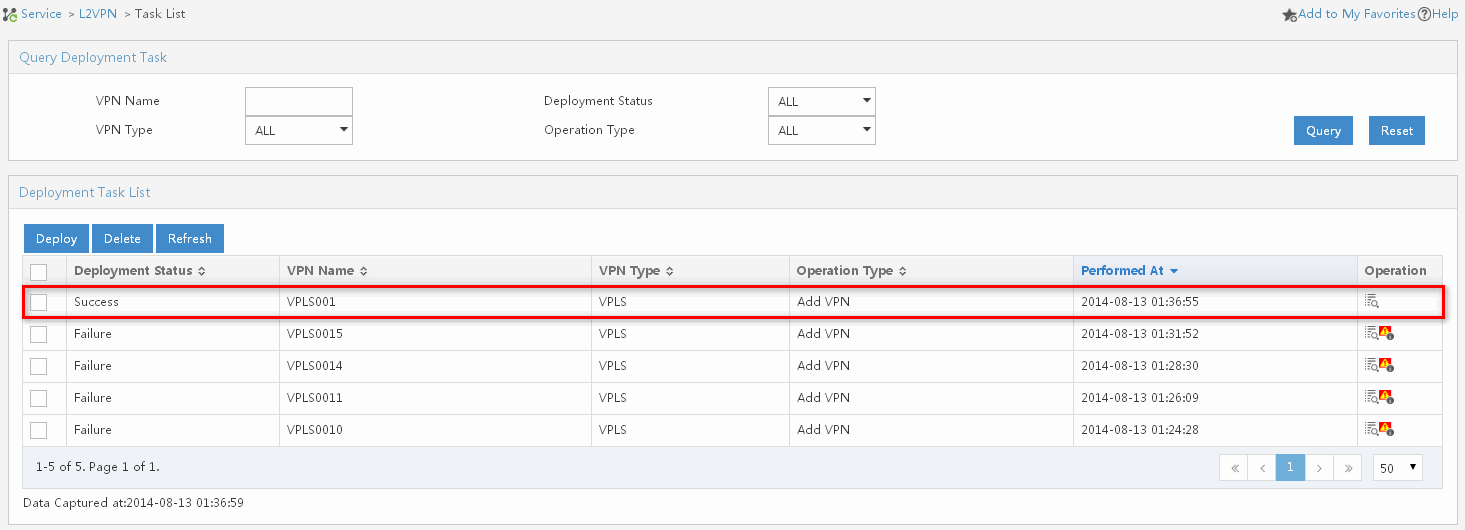
Viewing the VPN topology
1. Click the Service tab.
2. From the navigation tree, select L2VPN Manager > L2VPN Topology.
The L2VPN topology page opens.
3. On the toolbar at the top of the topology page, click the VPN List icon.
The VPN List tab is displayed at the right of the topology.
4. Configure the following query criteria:
¡ Name—Enter VPN name VPLS001.
¡ Type—Select VPLS from the list.
5. Click Query.
All matching devices are displayed in the VPN List area.
6. Double click a VPN in the VPN List.
The topology for the VPN is displayed, as shown in Figure 21.
Figure 21 VPLS001 topology
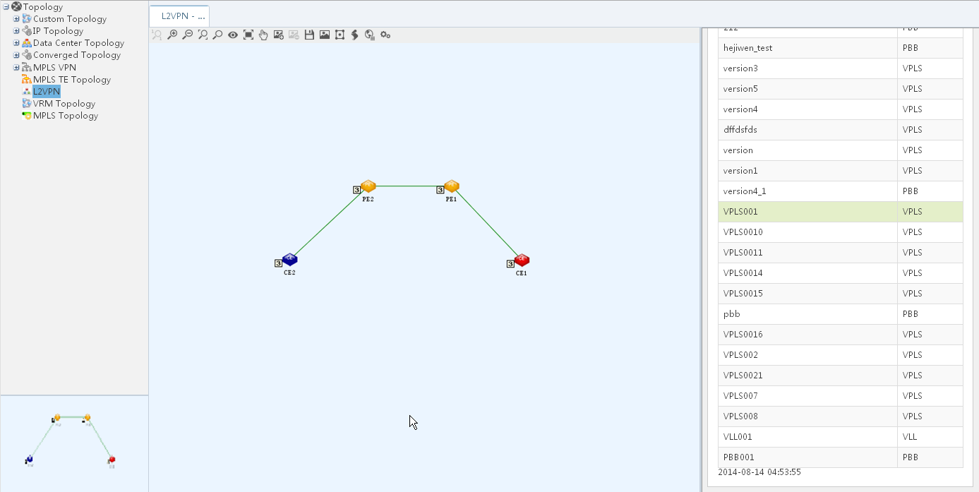
Configuring an LDP H-VPLS VPN
Network requirements
As shown in Figure 22, a customer has two sites CE 1 and CE 3. Configure an LDP H-VPLS VPN so that the customer sites can communicate with each other.
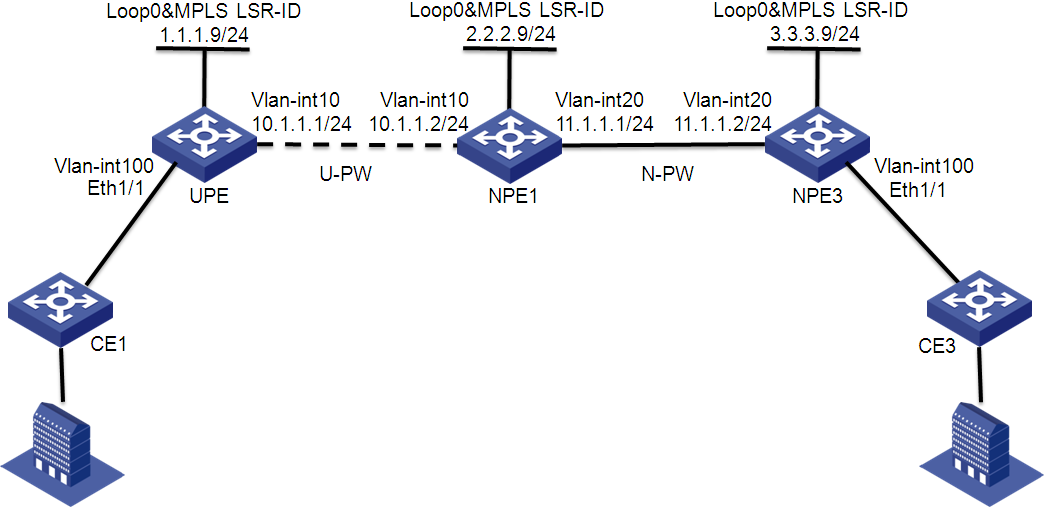
Configuring UPE and NPEs
Configuring UPE
1. Configure basic MPLS.
<Sysname> system-view
[Sysname] sysname UPE
[UPE] interface loopback 0
[UPE-LoopBack0] ip address 1.1.1.9 32
[UPE-LoopBack0] quit
[UPE] mpls lsr-id 1.1.1.9
[UPE] mpls
[UPE-mpls] quit
[UPE] mpls ldp
[UPE-mpls-ldp] quit
2. Configure basic MPLS on the interface that connects to NPE 1.
[UPE] interface vlan-interface 10
[UPE-Vlan-interface10] ip address 10.1.1.1 24
[UPE-Vlan-interface10] mpls
[UPE-Vlan-interface10] mpls ldp
[UPE-Vlan-interface10] quit
3. Configure an LDP session with NPE 1.
[UPE] mpls ldp remote-peer 1
[UPE-mpls-remote-1] remote-ip 2.2.2.9
[UPE-mpls-remote-1] quit
4. Enable L2VPN and MPLS L2VPN.
[UPE] l2vpn
[UPE-l2vpn] mpls l2vpn
[UPE-l2vpn] quit
Configuring NPE 1
1. Configure basic MPLS.
<Sysname> system-view
[Sysname] sysname NPE1
[NPE1] interface loopback 0
[NPE1-LoopBack0] ip address 2.2.2.9 32
[NPE1-LoopBack0] quit
[NPE1] mpls lsr-id 2.2.2.9
[NPE1] mpls
[NPE1–mpls] quit
[NPE1] mpls ldp
[NPE1–mpls-ldp] quit
2. Configure basic MPLS on the interface that connects to UPE.
[NPE1] interface vlan-interface 10
[NPE1-Vlan-interface10] ip address 10.1.1.2 24
[NPE1-Vlan-interface10] mpls
[NPE1-Vlan-interface10] mpls ldp
[NPE1-Vlan-interface10] quit
3. Configure basic MPLS on the interface that connects to NPE 3.
[NPE1] interface vlan-interface 20
[NPE1-Vlan-interface20] ip address 11.1.1.1 24
[NPE1-Vlan-interface20] mpls
[NPE1-Vlan-interface20] mpls ldp
[NPE1-Vlan-interface20] quit
4. Enable L2VPN and MPLS L2VPN.
[NPE1] l2vpn
[NPE1-l2vpn] mpls l2vpn
[NPE1-l2vpn] quit
Configuring NPE 3
1. Configure basic MPLS.
<Sysname> system-view
[Sysname] sysname NPE3
[NPE3] interface loopback 0
[NPE3-LoopBack0] ip address 3.3.3.9 32
[NPE3-LoopBack0] quit
[NPE3] mpls lsr-id 3.3.3.9
[NPE3] mpls
[NPE3–mpls] quit
[NPE3] mpls ldp
[NPE3–mpls-ldp] quit
2. Configure basic MPLS on the interface that connects to NPE 1.
[NPE3] interface vlan-interface 20
[NPE3-Vlan-interface20] ip address 11.1.1.2 24
[NPE3-Vlan-interface20] mpls
[NPE3-Vlan-interface20] mpls ldp
[NPE3-Vlan-interface20] quit
3. Enable L2VPN and MPLS L2VPN.
[NPE3] l2vpn
[NPE3-l2vpn] mpls l2vpn
[NPE3-l2vpn] quit
Configuring L2VPN Management
Importing CE 1 and CE 3
1. Click the Service tab.
2. From the navigation tree, select L2VPN Manager > VPN Devices > CE Devices.
The CE Devices page displays all CE devices.
3. Click Import CE on top of the CE Device List area.
The Import Device page opens.
4. Click Select Device to select CE 1 and CE 3.
5. Click OK to display the Import Device page.
6. Click OK.
The page for import results opens. You can see that the two CEs are imported.
Importing UPE, NPE 1, and NPE 3
1. Click the Service tab.
2. From the navigation tree, select L2VPN Manager > VPN Devices > PE Devices.
The PE Devices page displays all PE devices.
3. Click Import PE on top of the PE Devices area.
The Import Device page opens.
4. Click Select Device to select UPE, NPE 1, and NPE 3.
5. Click OK to display the Import Device page.
6. Click OK.
The page for import results opens. You can see that the three PEs are imported.
Deploying a hierarchical VPLS VPN
1. Click the Service tab.
2. From the navigation tree, select L2VPN Manager > VPN Deployment > Deploy VPLSs.
The VPLS deployment guide page opens.
3. Define a VPN:
a. In the PE Type area, select Hierarchical PE.
b. In the VPN Configuration area, configure the following parameters:
- VPN Operation Type—Select Add VPN.
- VPN Name—Enter VPN name VPLS002.
- VSI ID—Use the default value.
- PW Transport Mode—Select VLAN from the list.
- Audit Interval (in hours)—Use the default value 24.
- Description—Enter This is a hierarchical VPLS VPN as the description.
- Contact—Use the default value admin.
c. Click Next.
4. Add the AC from CE 3 to NPE 3:
a. Click Add on top of the AC List area.
The Select Interfaces window opens.
b. Select NPE 3 in the Device List, and click OK.
The Interface List tab is displayed.
c. Select Eth 1/1 that connects to CE 3, and click OK.
The Config UNI Interface page automatically opens.
d. Configure the following parameters:
- Service Instance—Enter service instance ID 500.
- Bandwidth (Mbps)—This field is not required. If you enter a value, L2VPN Management monitors the AC traffic from CE 3 to NPE 3.
- Encap Type—Select S-VID from the list.
- Encap VLAN—Enter a value of 100.
- Access Type—Select VLAN from the list.
- CE Device—Click Select next to the CE device box. On the Select Interfaces window that opens, select CE 3 and click OK to return to the Config UNI Interface page.
e. Click OK to return to the PE Configuration page.
f. Click Next.
5. Add the AC from CE 1 to UPE:
a. Click Add on top of the AC List area.
The Select Interfaces window opens.
b. Select UPE in the Device List, and click OK.
The Interface List tab is displayed.
c. Select Eth 1/1 that connects to CE 1, and click OK.
The Config UNI Interface page automatically opens.
d. Configure the following parameters:
- Service Instance—Enter service instance ID 500.
- Bandwidth (Mbps)—This field is not required. If you enter a value, L2VPN Management monitors the AC traffic from CE 1 to UPE.
- Encap Type—Select S-VID from the list.
- Encap VLAN—Enter a value of 100.
- Access Type—Select VLAN from the list.
- CE Device—Click Select next to the CE device box. On the Select Interfaces window that opens, select CE 1 and click OK to return to the Config UNI Interface page.
e. Click OK to return to the PE Configuration page.
f. Select a UPE from the UPE Device List, and click Main NPE.
g. On the page that opens, click OK.
L2VPN Management automatically generates a PW between UPE and NPE 1, and between NPE 1 and NPE 3. The PW information is displayed in the PW List area.
Each PW uses the default tunnel policy that only one tunnel is selected (no load balancing) in this order: LSP tunnel, GRE tunnel, and CRLSP tunnel.
h. Click Next.
The Configuration Summary page opens. You can view VPN information, and configurations to be deployed to UPE, NPE 1, and NPE 3.
6. Select Deploy Immediately and click OK.
The Task List page opens. You can view the VPN deployment results, as shown in Figure 23.
Figure 23 VPN deployment results
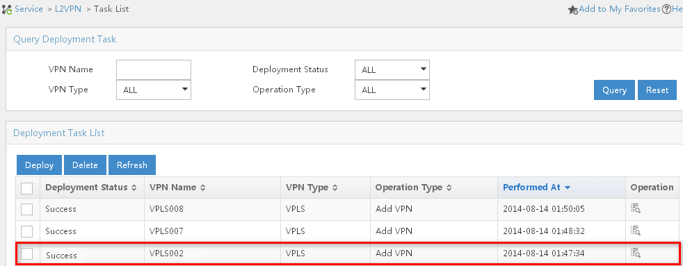
Viewing the VPN topology
1. Click the Service tab.
2. From the navigation tree, select L2VPN Manager > L2VPN Topology.
The L2VPN topology page opens.
3. On the toolbar at the top of the topology page, click VPN List.
The VPN List tab is displayed at the right of the topology.
4. Configure the following query criteria:
¡ Name—Enter VPN name VPLS002.
¡ Type—Select VPLS from the list.
5. Click Query.
All matching devices are displayed in the VPN List area.
6. Double-click a VPN in the VPN List.
The topology for the VPN is displayed, as shown in Figure 24.
Figure 24 VPLS002 topology
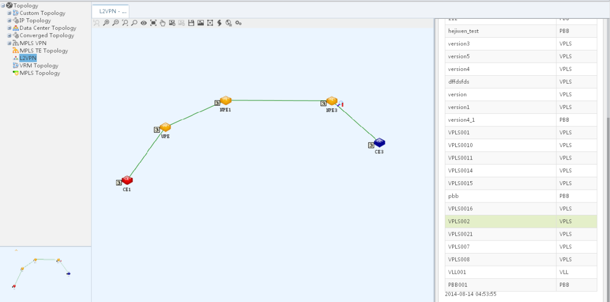
Configuring a VLL VPN
Network requirements
As shown in Figure 25, a customer has two sites CE 1 and CE 2 that connect to PE 1 and PE 2 through VLAN 10. Configure a VLL VPN so that the customer sites can communicate with each other.
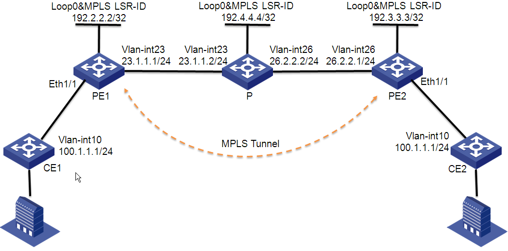
Configuring devices
Configuring CE 1
# Configure an IP address for VLAN-interface 10 that connects to PE 1.
<Sysname> system-view
[Sysname] sysname CE1
[CE1] interface vlan-interface 10
[CE1-Vlan-interface10] ip address 100.1.1.1 24
Configuring PE 1
1. Configure a loopback interface and its IP address.
<Sysname> system-view
[Sysname] sysname PE1
[PE1] interface loopback 0
[PE1-LoopBack0] ip address 192.2.2.2 32
[PE1-LoopBack0] quit
2. Configure the LSR ID and enable MPLS globally.
[PE1] mpls lsr-id 192.2.2.2
[PE1] mpls
[PE1-mpls] quit
3. Enable L2VPN and MPLS L2VPN.
[PE1] l2vpn
[PE1-l2vpn] mpls l2vpn
[PE1-l2vpn] quit
4. Enable LDP globally.
[PE1] mpls ldp
[PE1-mpls-ldp] quit
5. Establish a remote LDP session to PE 2.
[PE1] mpls ldp remote-peer 1
[PE1-mpls-ldp-remote-1] remote-ip 192.3.3.3
[PE1-mpls-ldp-remote-1] quit
6. Configure VLAN-interface 23 that connects to the P device, and enable LDP on the interface.
[PE1] interface vlan-interface 23
[PE1-Vlan-interface23] ip address 23.1.1.1 24
[PE1-Vlan-interface23] mpls
[PE1-Vlan-interface23] mpls ldp
[PE1-Vlan-interface23] quit
7. Configure OSPF for LSP establishment.
[PE1] ospf
[PE1-ospf-1] area 0
[PE1-ospf-1-area-0.0.0.0] network 23.1.1.1 0.0.0.255
[PE1-ospf-1-area-0.0.0.0] network 192.2.2.2 0.0.0.0
[PE1-ospf-1-area-0.0.0.0] quit
[PE1-ospf-1] quit
Configuring the P device
1. Configure a loopback interface and its IP address.
<Sysname> system-view
[Sysname] sysname P
[P] interface loopback 0
[P-LoopBack0] ip address 192.4.4.4 32
[P-LoopBack0] quit
2. Configure the LSR ID and enable MPLS globally.
[P] mpls lsr-id 192.4.4.4
[P] mpls
[P-mpls] quit
3. Enable LDP globally.
[P] mpls ldp
[P-mpls-ldp] quit
4. Configure VLAN-interface 23 that connects to PE 1, and enable LDP on the interface.
[P] interface vlan-interface 23
[P-Vlan-interface23] ip address 23.1.1.2 24
[P-Vlan-interface23] mpls
[P-Vlan-interface23] mpls ldp
[P-Vlan-interface23] quit
5. Configure VLAN-interface 26 that connects to PE 2, and enable LDP on the interface.
[P] interface vlan-interface 26
[P-Vlan-interface26] ip address 26.2.2.2 24
[P-Vlan-interface26] mpls
[P-Vlan-interface26] mpls ldp
[P-Vlan-interface26] quit
6. Configure OSPF for LSP establishment.
[P] ospf
[P-ospf-1] area 0
[P-ospf-1-area-0.0.0.0] network 23.1.1.2 0.0.0.255
[P-ospf-1-area-0.0.0.0] network 26.2.2.2 0.0.0.255
[P-ospf-1-area-0.0.0.0] network 192.4.4.4 0.0.0.0
[P-ospf-1-area-0.0.0.0] quit
[P-ospf-1] quit
Configuring PE2
1. Configure a loopback interface and its IP address.
<Sysname> system-view
[Sysname] sysname PE2
[PE2] interface loopback 0
[PE2-LoopBack0] ip address 192.3.3.3 32
[PE2-LoopBack0] quit
2. Configure the LSR ID and enable MPLS globally.
[PE2] mpls lsr-id 192.3.3.3
[PE2] mpls
[PE2-mpls] quit
3. Enable L2VPN and MPLS L2VPN.
[PE2] l2vpn
[PE2-l2vpn] mpls l2vpn
[PE2-l2vpn] quit
4. Enable LDP globally.
[PE2] mpls ldp
[PE2-mpls-ldp] quit
5. Establish a remote LDP session to PE 1.
[PE2] mpls ldp remote-peer 2
[PE2-mpls-ldp-remote-2] remote-ip 192.2.2.2
[PE2-mpls-ldp-remote-2] quit
6. Configure VLAN-interface 26 that connects to the P device, and enable LDP on the interface.
[PE2] interface vlan-interface 26
[PE2-Vlan-interface26] ip address 26.2.2.1 24
[PE2-Vlan-interface26] mpls
[PE2-Vlan-interface26] mpls ldp
[PE2-Vlan-interface26] quit
7. Configure OSPF for LSP establishment.
[PE2] ospf
[PE2-ospf-1] area 0
[PE2-ospf-1-area-0.0.0.0] network 192.3.3.3 0.0.0.0
[PE2-ospf-1-area-0.0.0.0] network 26.2.2.0 0.0.0.255
[PE2-ospf-1-area-0.0.0.0] quit
[PE2-ospf-1] quit
Configuring CE 2
# Configure an IP address for VLAN-interface 10 that connects to PE 2.
<Sysname> system-view
[Sysname] sysname CE2
[CE2] interface vlan-interface 10
[CE2-Vlan-interface10] ip address 100.1.1.2 24
Configuring L2VPN Management
Importing CE 1 and CE 2
1. Click the Service tab.
2. From the navigation tree, select L2VPN Manager > VPN Devices > CE Devices.
The CE Devices page displays all CE devices.
3. Click Import CE on top of the CE Device List area.
The Import Device page opens.
4. Click Select Device to select CE 1 and CE 2.
5. Click OK to display the Import Device page.
6. Click OK.
The page for import results opens. You can see that the two CEs are imported.
Importing PE 1 and PE 2
1. Click the Service tab.
2. From the navigation tree, select L2VPN Manager > VPN Devices > PE Devices.
The PE Devices page displays all PE devices.
3. Click Import PE on top of the PE Devices area.
The Import Device page opens.
4. Click Select Device to select PE 1 and PE 2.
5. Click OK to display the Import Device page.
6. Click OK.
The page for import results opens. You can see that the two PEs are imported.
Deploying a VLL VPN
1. Click the Service tab.
2. From the navigation tree, select L2VPN Manager > VPN Deployment > Deploy VLLs.
The VLL deployment guide page opens.
3. Define a VPN:
a. Configure the following parameters:
- VPN Name—Enter VPN name VLL001.
- PW ID—Use the default value.
- PW Transport Mode—Select VLAN from the list.
- Tunnel Policy—Select default from the list.
- Audit Interval—Use the default value 24. The interval is in hours.
- Description—Enter This is a VLL VPN as the description.
- Contact—Use the default value admin.
b. Click Next.
4. Configure the local PE:
a. Click Select next to the UNI Interface box.
i On the window that opens, select PE 1 in the Device List, and click OK.
The Interface List tab is displayed.
ii Select Eth 1/1 (the interface connected to CE 1), and click OK to return to the Local PE Configuration page.
b. Configure the following parameters:
- Service Instance—Enter service instance ID 2000.
- Bandwidth (Mbps)—This field is not required. If you enter a value, L2VPN Management monitors the AC traffic from CE 1 to PE 1.
- Encap Type—Select S-VID from the list.
- Encapsulation VLAN—Enter a value of 10.
- Access Type—Select VLAN from the list.
- CE Device—Click Select next to the CE device box. On the Select Interfaces window that opens, select CE 1 and click OK to return to the Local PE Configuration page.
c. Click Next.
5. Configure the remote PE:
a. Click Select next to the UNI Interface box.
i On the window that opens, select PE 1 in the Device List, and click OK.
The Interface List tab is displayed.
ii Select Eth 1/1 (the interface connected to CE 1), and click OK to return to the Remote PE Configuration page.
b. Configure the following parameters:
- Service Instance—Enter service instance ID 2000.
- Bandwidth (Mbps)—This field is not required. If you enter a value, L2VPN Management monitors the AC traffic from CE 1 to PE 1.
- Encap Type—Select S-VID from the list.
- Encapsulation VLAN—Enter a value of 10.
- Access Type—Select VLAN from the list.
- CE Device—Click Select next to the CE device box. On the Select Interfaces window that opens, select CE 2 and click OK to return to the Remote PE Configuration page.
c. Click Next.
The Configuration Summary page opens. You can view VPN information, and configurations to be deployed to PE 1 and PE 2.
6. Select Deploy Immediately and click OK.
The Task List page opens. You can view the VPN deployment results, as shown in Figure 26.
Figure 26 VLL001 deployment results
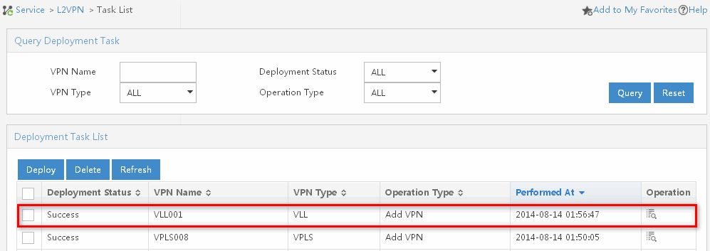
Viewing the VPN topology
1. Click the Service tab.
2. From the navigation tree, select L2VPN Manager > L2VPN Topology.
The L2VPN topology page opens.
3. On the toolbar at the top of the topology page, click VPN List.
The VPN List tab is displayed at the right of the topology.
4. Configure the following query criteria:
¡ Name—Enter VPN name VLL001.
¡ Type—Select VLL from the list.
5. Click Query.
All matching devices are displayed in the VPN List area.
6. Double-click a VPN in the VPN List.
The topology for the VPN is displayed, as shown in Figure 27.
Figure 27 VLL001 topology
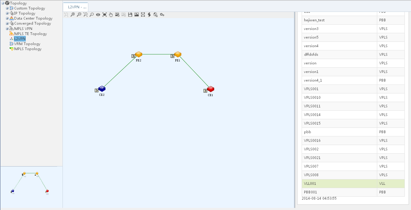
Configuring a PBB network
Network requirements
As shown in Figure 28, a customer has two sites Customer network A and Customer network B that connect to BEB 1 and BEB 2. Configure a PBB network so that the customer sites can communicate with each other at Layer 2.
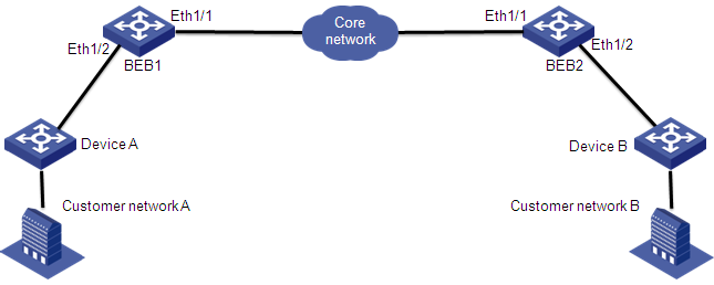
Configuring BEBs
Configuring BEB 1
# Create VLAN 20.
<BEB1> system-view
[BEB1] vlan 20
[BEB1-vlan20] quit
# Enable L2VPN.
[BEB1] l2vpn
[BEB1-l2vpn] quit
# Configure the uplink port Ethernet 1/1 as a trunk port, and configure the port to permit packets from VLAN 20 to pass.
[BEB1] interface ethernet 1/1
[BEB1-Ethernet1/1] port link-type trunk
[BEB1-Ethernet1/1] port trunk permit vlan 20
[BEB1-Ethernet1/1] quit
# # Configure the downlink port Ethernet 1/2 as a trunk port, and configure the port to permit packets from all VLANs to pass.
[BEB1] interface ethernet 1/2
[BEB1-Ethernet1/2] port link-type trunk
[BEB1-Ethernet1/2] port trunk permit vlan all
[BEB1-Ethernet1/2] quit
Configuring BEB 2
Configure BEB 2 in the same way that BEB 1 is configured. Details not shown.
Configuring L2VPN Management
Importing Device A and Device B
1. Click the Service tab.
2. From the navigation tree, select L2VPN Manager > VPN Devices > CE Devices.
The CE Devices page displays all CE devices.
3. Click Import CE on top of the CE Device List area.
The Import Device page opens.
4. Click Select Device to select Device A and Device B.
5. Click OK to display the Import Device page.
6. Click OK.
The page for import results opens. You can see that the two devices are imported.
Importing BEB 1 and BEB 2
1. Click the Service tab.
2. From the navigation tree, select L2VPN Manager > VPN Devices > PE Devices.
The PE Devices page displays all PE devices.
3. Click Import PE on top of the PE Devices area.
The Import Device page opens.
4. Click Select Device to select BEB 1 and BEB 2.
5. Click OK to display the Import Device page.
6. Click OK.
The page for import results opens. You can see that the two PEs are imported.
Deploying a PBB network
1. Click the Service tab.
2. From the navigation tree, select L2VPN Manager > VPN Deployment > Deploy PBBs.
The PBB deployment guide page opens.
3. Define a VPN:
a. Configure the following parameters:
- VPN Operation Type—Select Add VPN.
- VPN Name—Enter VPN name PBB001.
- I-SID—Use the default value.
- B-VLAN—Enter 20.
- PW Transport Mode—Select Ethernet from the list.
- Audit Interval (in hours)—Use the default value 24.
- Description—Enter This is a PBB network as the description.
- Contact—Use the default value admin.
b. Click Next.
4. Add the AC from Device A to BEB 1:
a. Click Add on top of the AC List area.
The Select Interfaces window opens.
b. Select BEB 1 in the Device List, and click OK.
The Interface List tab is displayed.
c. Select Eth 1/2 that connects to Device A, and click OK.
The Configure Interface page automatically opens.
d. Configure the following parameters:
- Service Instance—Enter service instance ID 3000.
- Bandwidth (Mbps)—This field is not required. If you enter a value, L2VPN Management monitors the AC traffic from Device A to BEB 1.
- Encap Type—Select Port-based from the list.
- Access Type—Select Ethernet from the list.
- CE Device—Click Select next to the CE device box. On the Select Interfaces window that opens, select Device A and click OK to return to the Configure Interface page.
e. Click OK to return to the PE Configuration page.
5. Add the AC from Device B to BEB 2 in the same way that Device A-BEB 1 AC is configured.
6. Configure the NNI interfaces on the PEs:
a. On the PE Device List area, click the Configuration icon for BEB 1.
b. On the window that opens, select Eth 1/1 and click OK.
c. On the PE Device List area, click the Configuration icon for BEB 2.
d. On the window that opens, select Eth 1/1 and click OK.
7. Click Next.
The Configuration Summary page opens. You can view VPN information, and configurations to be deployed to BEB 1 and BEB 2.
8. Select Deploy Immediately and click OK.
The Task List page opens. You can view the VPN deployment results, as shown in Figure 29.
Figure 29 PBB001 deployment results
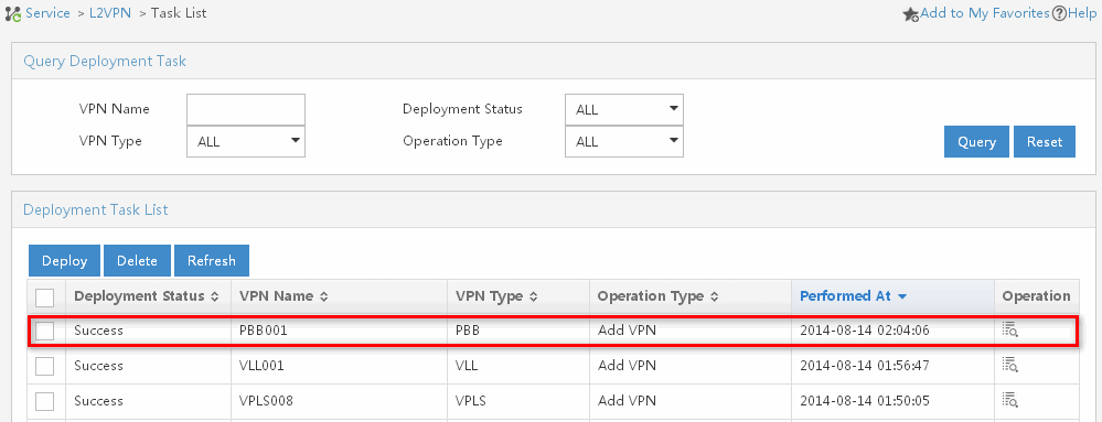
Viewing the VPN topology
1. Click the Service tab.
2. From the navigation tree, select L2VPN Manager > L2VPN Topology.
The L2VPN topology page opens.
3. On the toolbar at the top of the topology page, click the VPN List icon.
The VPN List tab is displayed at the right of the topology.
4. Configure the following query criteria:
¡ Name—Enter VPN name PBB001.
¡ Type—Select PBB from the list.
5. Click Query.
All matching devices are displayed in the VPN List area.
6. Double-click a VPN in the VPN List.
The topology for the VPN is displayed, as shown in Figure 30.
Figure 30 PBB001 topology
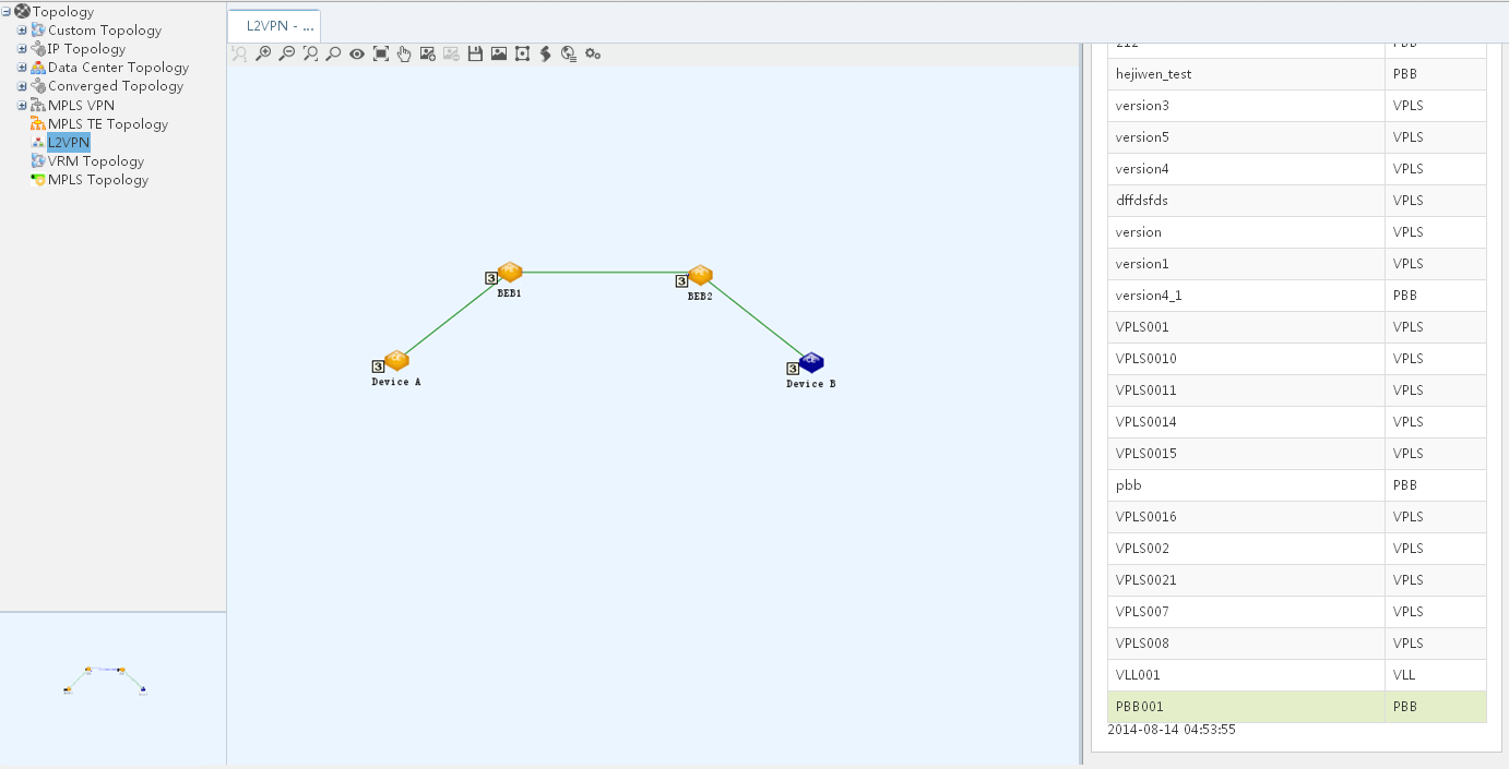
Using L2VPN Management with BGP protocol
This section provides a quick start for deploying and managing BGP VPLS VPNs.
Figure 31 BGP VPLS VPNs quick start
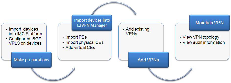
As shown in Figure 31, the quick start includes the following steps:
1. Make preparations:
¡ Import PE and CE devices into IMC Platform, and configure correct SNMP parameters and BGP VPLS for the devices.
¡ To build BGP VPLS, you must enable MPLS, and MPLS L2VPN on PEs. For details, see the corresponding configuration guides and command references.
2. Import devices into L2VPN Management:
¡ For VPLS VPNs, import PEs. For details, see "Importing PE devices."
¡ Import physical CEs. For details, see "Importing CE devices."
¡ Import virtual CEs (VCEs). For details, see "Adding/Modifying a VCE."
3. Add VPNs:
¡ Add existing VPNs to L2VPN Management through auto discovery. For details, see "Automatic discovery."
4. Maintain VPNs
You can view VPN topology, alarms, and audit information.
The following content will introduce how to use L2VPN Management deployed BGP protocol.
VPN devices
VPN devices include PEs and CEs in MPLS Layer 2 VPNs. A PE provides VPN access by translating data link layer frames to Layer 2 VPN packets. A CE only needs to establish a link layer connection with a PE. You can import, synchronize, view, and query PEs and CEs. In addition, you can create non-managed CEs (called VCEs) to represent CEs that cannot be managed by L2VPN Management.
PE devices
The first step to deploy a VPN is to import PEs to L2VPN Management. Then, you can synchronize and delete PEs, and view VPN information on the PEs. To enhance management, you can use the configuration comparison function to discover configuration changes on the PEs.
Viewing PE devices
1. Click the Service tab.
2. From the navigation tree, select L2VPN Manager > VPN Devices > PE Devices.
The PE Devices page displays all PE devices.
PE Devices contents
¡ Status—Alarm state of the device. Options are Critical, Major, Minor, Warning, Normal, Unknown, and Unmanaged.
¡ Device Label—Label and IP address of the device. Click the device label link to view its details.
¡ LSR ID—LSR ID of the PE device. An LSR ID uniquely identifies an LSR in an MPLS network.
¡ Last Synchronization Time—Time when the last synchronization occurred, in the format YYYY-MM-DD hh:mm:ss.
¡ Synchronization Status—Synchronization state of the PE. Options are Synchronizing, Success, and Failure. When the synchronization fails, click the Failure link to view the causes in the prompt box that opens.
¡ Config Comparison—Configuration comparison results. Options are Same Config and Different Config. When the synchronization begins, L2VPN Management compares the PE configuration with the baseline configuration. When they are different, you can click the Different Config link to view the differences in the configuration comparison result page.
¡ Details—Click
the Details icon ![]() to view the VSI information for the device on the page for the device's
VPN information.
to view the VSI information for the device on the page for the device's
VPN information.
3. Click Refresh to view the latest PE Devices.
Querying PE devices
1. Click the Service tab.
2. From the navigation tree, select L2VPN Manager > VPN Devices > PE Devices.
The PE Devices page displays all PE devices.
3. Enter or select one or more of the following query criteria:
¡ Device Label—Enter the label of the PE to be queried. L2VPN Management supports fuzzy matching for this field.
¡ LSR ID—Enter the LSR ID of the PE to be queried. L2VPN Management supports fuzzy matching for this field.
¡ Device IP—Enter the IP address of the PE to be queried. L2VPN Management supports fuzzy matching for this field.
¡ Device Status—Select the alarm state of the PE to be queried. Options are All, Unmanaged, Unknown, Normal, Warning, Minor, Major, and Critical.
4. Click Query.
The PE Devices displays all PEs matching the query criteria.
5. Click Reset to clear the query criteria and display all PEs.
Importing PE devices
1. Click the Service tab.
2. From the navigation tree, select L2VPN Manager > VPN Devices > PE Devices.
The PE Devices page displays all PE devices.
3. Click Import PE on top of the PE Devices area.
The Import Device page opens.
4. Click Select Device to select the PEs to be imported.
There are two methods for selecting devices, By View or using the Advanced option. See "Adding devices by view" and "Adding devices by advanced query."
5. Highlight the devices you want to select and do one of the following:
¡ To
add the devices to the Selected Devices list, click
Add selected ![]() .
.
¡ To
select all of the devices displayed in the Devices Found
list, click Add all ![]() .
.
¡ To
remove one or more devices,
select the devices and click Remove selected ![]() .
.
¡ To
remove all of the selected devices, click Remove all
![]() .
.
6. Confirm that the devices you found have been added.
7. Click OK to display the Import Device page.
The selected devices appear in the page.
8. Verify the imported devices.
¡ To add more devices, repeat step 4.
¡ To delete devices, select one or more devices in the PE Devices and click Delete.
9. Click OK.
You can view the import process and results in the Import Device page.
Viewing L2VPN information on a PE
1. Click the Service tab.
2. From the navigation tree, select L2VPN Manager > VPN Devices > PE Devices.
The PE Devices page displays all PE devices.
3. Click the Details icon ![]() for a PE to
display the L2VPN information page for the PE.
for a PE to
display the L2VPN information page for the PE.
Discovered VSI List contents
¡ VSI Name—Name of the VSI.
¡ Protocol Type—Protocol type for the VSI.
¡ Import RT—Value of the import RT with which the VSI associates.
¡ Export RT—Value of the export RT with which the VSI associates.
¡ RD—RD value of the VSI.
¡ MAC Learning Status—Whether MAC address learning is Enabled or Disabled.
¡ Tunnel Policy—Tunnel policy that the VSI uses.
¡ Binding Information—Click the Binding Information icon ![]() to display the Binding
Information page. You can view the binding
interface, encapsulation type, service instance ID, bandwidth, and VLAN ID on
the page.
to display the Binding
Information page. You can view the binding
interface, encapsulation type, service instance ID, bandwidth, and VLAN ID on
the page.
Synchronizing PE devices
This function immediately synchronizes device configurations to L2VPN Management. L2VPN Management compares the device configurations with the baseline configurations, and displays the differences in the PE Devices page.
1. Click the Service tab.
2. From the navigation tree, select L2VPN Manager > VPN Devices > PE Devices.
The PE Devices page displays all PE devices.
3. Select one or more PEs to be synchronized and click Synchronize.
The synchronization results are displayed in the Synchronization Status field.
4. Click Refresh to view the latest PE Devices and view the final synchronization results.
Removing PE devices
This function removes the PE devices from L2VPN Management.
1. Click the Service tab.
2. From the navigation tree, select L2VPN Manager > VPN Devices > PE Devices.
The PE Devices page displays all PE devices.
3. Select one or more PEs to be deleted and click Delete.
A confirmation dialog box opens.
4. Click OK.
CE devices
CE devices include common CEs and virtual CEs (VCEs). Common CEs are physical CEs that can be managed by IMC. You can import and synchronize common CEs, and configure VLAN mappings for them. VCEs represent the physical CEs that cannot be managed by IMC. You can add, synchronize, and modify VCEs.
Viewing the CE device list
1. Click the Service tab.
2. From the navigation tree, select L2VPN Manager > VPN Devices > CE Devices.
The CE Devices page displays all CE devices.
CE Devices List contents
¡ Status—Alarm state of the device. Options are Critical, Major, Minor, Warning, Normal, Unknown, and Unmanaged.
¡ Device Label—Label for the CE/VCE. For a CE, this field displays its device label and IP address. Click the device label link to view its details. For a manually configured VCE, this field displays its device label. For an automatically generated VCE, this field displays VCE-(Sequence number). For example, VCE-1. Click the VCE device label to view its device label and MAC address.
¡ CE Type—Type of the CE. Options are CE and VCE.
¡ MAC Address—MAC address of the CE.
¡ Last Synchronization Time—Time when the last synchronization occurred, in the format YYYY-MM-DD hh:mm:ss.
¡ Synchronization Status—Synchronization state of the CE. Options are Synchronizing, Success, and Failed.
¡ Operation—For
a physical CE, this field displays the VLAN mapping icon ![]() . Click
the icon to display the VLAN Mapping
List page where you can configure the
CVLAN-SVLAN mapping. For a VCE, this field displays the Modify icon
. Click
the icon to display the VLAN Mapping
List page where you can configure the
CVLAN-SVLAN mapping. For a VCE, this field displays the Modify icon ![]() . Click the icon to
display the Modify MCE page.
. Click the icon to
display the Modify MCE page.
3. Click Refresh to view the latest CE Device List.
Querying CE devices
1. Click the Service tab.
2. From the navigation tree, select L2VPN Manager > VPN Devices > CE Devices.
The CE Devices page displays all CE devices.
3. Enter or select one or more of the following query criteria:
¡ Device Label—Enter the label of the CE to be queried. L2VPN Management supports fuzzy matching for this field.
¡ Device Status—Select the alarm state of the CE to be queried. Options are All, Unmanaged, Unknown, Normal, Warning, Minor, Major, and Critical.
¡ Device IP—Enter the IP address of the CE to be queried. L2VPN Management supports fuzzy matching for this field.
¡ CE Type—Select the type of the CE to be queried. Options are All, CE, and VCE.
4. Click Query.
The CE Device List displays all CEs matching the query criteria.
5. Click Reset to clear the query criteria and display all CEs.
Importing CE devices
Before importing CE devices, make sure the devices meet the following conditions:
· Enabled with SNMP.
· Added into IMC and managed by IMC.
· Not imported as PE devices.
1. Click the Service tab.
2. From the navigation tree, select L2VPN Manager > VPN Devices > CE Devices.
The CE Devices page displays all CE devices.
3. Click Import CE on top of the CE Device List area.
The Import Device page opens.
4. Click Select Device to select the CEs to be imported.
There are two methods for selecting devices, By View or using the Advanced option. See "Adding devices by view" and "Adding devices by advanced query."
5. Highlight the devices you want to select and do one of the following:
¡ To
add the devices to the Selected Devices list, click
Add selected ![]() .
.
¡ To
select all of the devices displayed in the Devices Found
list, click Add all ![]() .
.
¡ To
remove one or more devices, select the devices and click Remove
selected ![]() .
.
¡ To
remove all of the selected devices, click Remove all
![]() .
.
6. Confirm that the devices you found have been added.
7. Click OK to display the Import Device page.
The selected devices now appear in the page.
8. Verify the imported devices.
¡ To add more devices, repeat step 4.
¡ To delete devices, select one or more devices in the CE Device List and click Delete.
9. Click OK.
You can view the import process and results in the Import Device page.
Adding/Modifying a VCE
1. Click the Service tab.
2. From the navigation tree, select L2VPN Manager > VPN Devices > CE Devices.
The CE Devices page displays all CE devices.
3. Click Add VCE on top of the CE Device List area to display the Add
Non-managed CE page. Alternatively, click the
Modify icon ![]() in the Operation field for the VCE to be modified to display the Modify VCE page.
in the Operation field for the VCE to be modified to display the Modify VCE page.
4. Configure the following parameters:
¡ Device Label—Enter the device label.
¡ MAC Address—Enter the MAC address of the device.
5. Click OK.
Synchronizing CE devices
This function synchronizes the VLAN mappings on the CEs to L2VPN Management.
1. Click the Service tab.
2. From the navigation tree, select L2VPN Manager > VPN Devices > CE Devices.
The CE Devices page displays all CE devices.
3. Select one or more CEs to be synchronized and click Synchronize.
The synchronization results are displayed in the Synchronization Status field.
4. Click Refresh to view the latest CE Device List and view the final synchronization results.
Removing CE devices
Perform this task to remove CEs and VCEs from L2VPN Management. Removing CEs might result in an incomplete L2VPN or VPN service interruption. As a best practice, verify the CEs before you remove them.
1. Click the Service tab.
2. From the navigation tree, select L2VPN Manager > VPN Devices > CE Devices.
The CE Devices page displays all CE devices.
3. Select one or more CEs to be deleted and click Delete.
A confirmation dialog box opens.
4. Click OK.
Managing VPN resources
VPN resources include VPNs services and Attachment Circuit (ACs). A VPN service is a Layer 2 VPN. An AC is a link that connects a PE to a CE. L2VPN Management provides a VPN list and an AC list for you to manage all VPNs and ACs.
Managing VPNs
The VPN list shows all VPN services. You can add, modify, delete, and audit VPN services from the VPN list.
Viewing the VPN list
1. Click the Service tab.
2. From the navigation tree, select L2VPN Manager > VPN Resources > VPN List.
¡ Status—State of the VPN. Options are Critical, Major, Minor, Warning, Normal, Unknown, and Unmanaged.
¡ VSI Admin Status—State of the VSI, Enabled or Disabled.
¡ VPN name—Name of the VPN. You can click a VPN name to view details about that VPN.
¡ Topology—Provides a Topology link for you to view L2VPN topology.
¡ Audit Time—Time when the last VPN connectivity audit was performed, in the format YYYY-MM-DD hh:mm:ss.
¡ Audit Result—Result of the last VPN connectivity audit. Options are Unaudited, Normal, Auditing, Unknown, Unconnected, and Error. If the result is Unconnected, you can click the Unconnected link to view the cause.
¡ Modify—Provides
a Modify icon ![]() for you to
modify basic settings for a VPN.
for you to
modify basic settings for a VPN.
3. Click Refresh to view the latest VPN list.
Querying a VPN
1. Click the Service tab.
2. From the navigation tree, select L2VPN Manager > VPN Resources > VPN List.
3. Enter or select one or more of the following query criteria:
¡ VPN name—Enter the name of a VPN. This field supports fuzzy matching.
¡ Audit Result—Select an audit result. Options are All, Unaudited, Normal, Auditing, Unknown, Unconnected, and Error.
¡ VPN Status—Select a VPN state. Options are All, Critical, Major, Minor, Warning, Normal, Unknown, and Unmanaged.
¡ VSI Admin Status—Select a VSI state. Options are All, Enabled, and Disabled.
4. Click Query.
The VPN list displays all the matching VPNs. To clear the query results, click Reset.
Modifying basic VPN settings
L2VPN Management provides basic and advanced VPN settings. Basic settings include the VPN name, contact, description, and audit interval. Advanced settings include information about PEs, ACs, VLAN mappings, and alarms.
1. Click the Service tab.
2. From the navigation tree, select L2VPN Manager > VPN Resources > VPN List.
3. Click the Modify icon ![]() of
the target VPN.
of
the target VPN.
4. Modify the following settings:
¡ VPN Name—Enter a new VPN name.
¡ Contact—Enter a new contact.
¡ Description—Enter a new description.
¡ Audit Interval (in hours)—Enter a new audit interval in the range of 0 to 24. An audit interval of 0 disables audit function.
5. Click OK.
Enabling a VSI
1. Click the Service tab.
2. From the navigation tree, select L2VPN Manager > VPN Resources > VPN List.
3. Select one or more VPNs from the VPN list.
4. Click More Operations….
5. Select Enable VSI.
6. Click OK in the window that opens.
Deleting VPNs
This task deletes VPNs from L2VPN Management but the deleted VPNs still exist in the network. You can perform VPN auto-discovery to add the deleted VPNs to L2VPN Management. To delete a VPN from the network, you must undeploy the VPN.
1. Click the Service tab.
2. From the navigation tree, select L2VPN Manager > VPN Resources > VPN List.
3. Select one or more VPNs from the VPN list.
4. Click Delete.
5. Click OK in the window that opens.
Auditing VPNs
1. Click the Service tab.
2. From the navigation tree, select L2VPN Manager > VPN Resources > VPN List.
3. Select one or more VPNs from the VPN list.
4. Click Audit.
5. After a while, click Refresh to view the audit result.
Managing ACs
The AC list shows all ACs. You can view, query, and delete ACs from the AC list.
Viewing the AC list
1. Click the Service tab.
2. From the navigation tree, select L2VPN Manager > VPN Resources > AC List.
¡ PE Name—Name of the PE. You can click a PE name to view details about that PE.
¡ PE Interface Description—Displays the PE interface connected to the CE.
¡ CE Name—Name of the CE. You can click a CE name to view details about that CE.
¡ Attached VPN—VPN to which the AC belongs.
¡ Detail—Provides
a Detail icon ![]() for you to view details about the AC.
for you to view details about the AC.
3. Click Refresh to view the latest AC list.
Querying ACs
1. Click the Service tab.
2. From the navigation tree, select L2VPN Manager > VPN Resources > AC List.
3. Enter or select the following query criteria:
¡ PE Name—Enter a PE name. This field supports fuzzy matching.
¡ Attached VPN—Enter a VPN name. This field supports fuzzy matching.
¡ CE Name—Enter a CE name. This field supports fuzzy matching.
4. Click Query.
The VPN list displays all the matching ACs. To clear the query results, click Reset.
Deleting ACs
This task deletes ACs from L2VPN Management but the deleted ACs still exist in the network.
1. Click the Service tab.
2. From the navigation tree, select L2VPN Manager > VPN Resources > AC List.
3. Select ACs from the AC list.
4. Click Delete.
5. Click OK in the window that opens.
Automatic discovery
The auto discovery function collects configuration information from PE devices to obtain all existing L2VPNs and links, draws the L2VPN topology, and add the VPNs to L2VPN Management.
To automatically discover a VPN:
1. Click the Service tab.
2. From the navigation tree, select L2VPN Manager > Auto Discovery.
The auto discovery configuration guide page opens.
3. Select PEs:
a. Enable Synchronize PE device before auto discovery for Auto Discovery Parameter Settings.
b. Click Select PE for Auto Discovery Range Settings.
The Select Devices dialog box opens.
There are two methods for selecting devices, By View or using the Advanced option. See "Adding devices by view" and "Adding devices by advanced query."
c. Highlight the devices you want to select and do one of the following:
- To add the devices to the Selected Devices
list, click Add selected ![]() .
.
- To select all of the devices displayed in the Devices
Found list, click Add all ![]() .
.
- To remove one or more devices, select the devices and click Remove selected ![]() .
.
- To remove all of the selected devices, click Remove
all ![]() .
.
d. Confirm that the devices you found have been added.
e. Click OK to return to the page for selecting a PE.
f. To delete a device, click the Delete icon ![]() to which the
device to be deleted corresponds. To delete multiple devices, select the
devices and click Delete.
to which the
device to be deleted corresponds. To delete multiple devices, select the
devices and click Delete.
4. Click Auto Discovery.
A progress bar for VPN auto discovery is displayed.
5. Click Next when the loading is finished.
The VPN selection page opens.
6. Select VPNs whose links are to be configured:
a. View the VPN List Found.
VPN List Found contents
- Status—Status of the found VPN, Existed or New VPN. Existed indicates that the found VPN already exists in L2VPN Management. New VPN indicates that a new VPN is found.
- VPN Name—Name of the found VPN.
- VPN Protocol Type—Type of the found VPN. This field displays BGP.
- ID Value—The VPN target information of the found VPN.
- PW Transport Mode—PW transport mode. Options are VLAN and Ethernet.
- VPN Description—Description of the found VPN.
b. Select one or more VPNs in the VPN List Found.
c. Click Next.
7. Configure VRF binding relationships.
This step configures CE information for the new links.
a. Select or clear the Create non-managed CE automatically box.
If you select the Create non-managed CE automatically box, the system
automatically creates a non-managed CE for a link without any CE device. If you clear the Create
non-managed
CE automatically box,
click the Modify icon ![]() in the New Link List to manually specify a CE device for a link.
in the New Link List to manually specify a CE device for a link.
b. View the New Links List.
New Links List contents
- Device Label—Label and IP address of the PE device.
- VRF Name—Name of the found VRF.
- PE Interface—Name of the PE interface that connects to the CE device.
- Service Instance ID—ID of the service instance.
- CE Name—Name of the CE device.
- Modify—Click the Modify icon ![]() to display the Select Device page.
Select a CE device and click OK to return to the New
Links List.
to display the Select Device page.
Select a CE device and click OK to return to the New
Links List.
c. Select multiple links to add to L2VPN Management.
d. Click Finish.
The Summary page displays the VPN link configuration results.
VPN Link Configuration Result contents
· Device Label—Label and IP address of the PE device.
· VPN Name—Name of the VPN.
· PE Interface—Name of the PE device interface that connects to the CE device.
· CE Name—Name of the CE device.
· Result—Result of the VPN configuration, Success or Failure.
L2VPN topology
The L2VPN topology shows connections between PEs and CEs for each L2VPN. You can view L2VPN information for a PE device, view information about an AC, remove an AC, and audit a VPN.
Entering L2VPN topology
1. Click the Service tab.
2. From the navigation tree, select L2VPN Manager > L2VPN Topology.
The page that shows the topology opens.
Viewing a specific VPN topology
1. On the toolbar at the top of the topology page, click the VPN List icon.
The VPN List tab is displayed at the right of the topology.
2. Enter or select one or more of the following query criteria:
¡ Name—Enter the VPN name.
¡ Type—Select a VPN type from the list. Options are All and BGP.
3. Click Query.
The VPN List displays all VPNs matching the query criteria.
4. Click Reset to clear the query criteria, and display all VPNs.
5. Double-click a VPN in the VPN List.
The topology for the VPN is displayed.
Topology operations
Viewing device VPN information
1. Right-click a PE device.
2. Select L2VPN Info from the shortcut menu.
The page for the L2VPN information opens. For information about L2VPN information, see "Viewing L2VPN information on a PE."
Viewing PW information
1. Right-click the PW between two PEs.
2. Select PW Info from the shortcut menu.
The page for the PW information opens. You can view the PW connectivity status, left device, right device, PW type, PW encapsulation type, and failure reason on the page.
Auditing a VPN
1. Right-click the blank and select Audit from the shortcut menu.
The message Start VPN Auditing is displayed in the log area below the topology. After a period of time, you can view the audit results in the VPN List.
Application
In this chapter, PEs are H3C S95 and S75 series switches.
Configuration commands executed on the devices depend on the device model and software version. For more information about the commands in this chapter, see the manual for the device.
Managing an BGP VPLS VPN
Network requirements
As shown in Figure 32, a customer has two sites CE 1 and CE 2 that connect to PE 1 and PE 2 through VLAN 100. Configure an LDP VPLS VPN so that the customer sites can communicate in VLAN 100 over the MPLS network.
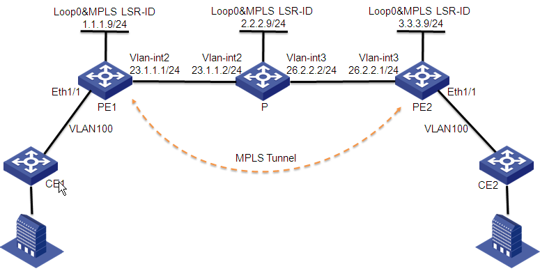
Importing CE 1 and CE 2
1. Click the Service tab.
2. From the navigation tree, select L2VPN Manager > VPN Devices > CE Devices.
The CE Devices page displays all CE devices.
3. Click Import CE on top of the CE Device List area.
The Import Device page opens.
4. Click Select Device to select CE 1 and CE 2.
5. Click OK to display the Import Device page.
6. Click OK.
The page for import results opens. You can see that the two CEs are imported.
Importing PE 1 and PE 2
1. Click the Service tab.
2. From the navigation tree, select L2VPN Manager > VPN Devices > PE Devices.
The PE Devices page displays all PE devices.
3. Click Import PE on top of the PE Devices area.
The Import Device page opens.
4. Click Select Device to select PE 1 and PE 2.
5. Click OK to display the Import Device page.
6. Click OK.
The page for import results opens. You can see that the two PEs are imported.
Auto Discovering BGP VPLS VPN
1. Click the Service tab.
2. From the navigation tree, select L2VPN Manager > Auto Discovery.
The auto discovery configuration guide page opens.
3. Select PEs:
a. Enable Synchronize PE device before auto discovery for Auto Discovery Parameter Settings.
b. Click Select PE to select PE1 and PE2.
4. Click Auto Discovery.
A process bar for VPN auto discovery is displayed.
5. Click Next when the loading is finished.
The VPN selection page opens.
6. Select VPNs whose links are to be configured:
a. Select VPN bbb in the VPN List Found.
b. Click Next.
7. Configure VRF binding relationships.
a. Click the Modify icon ![]() of the PE1 to display the Select Device page. Select CE1 and click OK to
return to the New Links List.
of the PE1 to display the Select Device page. Select CE1 and click OK to
return to the New Links List.
b. Click the Modify icon ![]() of the PE2 to display the
Select Device page. Select CE2 and
click OK to return to the New Links List.
of the PE2 to display the
Select Device page. Select CE2 and
click OK to return to the New Links List.
c. Select those two links to be added to L2VPN Management.
d. Click Finish.
Viewing the VPN topology
1. Click the Service tab.
2. From the navigation tree, select L2VPN Manager > L2VPN Topology.
The L2VPN topology page opens.
3. On the toolbar at the top of the topology page, click VPN List.
The VPN List tab is displayed at the right of the topology.
4. Configure the following query criteria:
¡ Name—Enter VPN name VPLS001.
¡ Type—Select VPLS from the list.
5. Click Query.
All matching devices are displayed in the VPN List area.
6. Double-click a VPN in the VPN List.
The topology for the VPN is displayed, as shown in Figure 33.
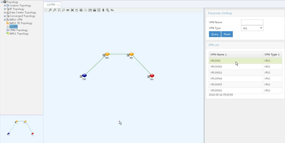
Using MPLS TE Management
MPLS TE Management overview
TE and MPLS
Network congestion is one of the major problems that can degrade your network performance. It might occur either when network resources are inadequate or load distribution is unbalanced.
TE can best utilize network resources and avoid uneven load distribution by real-time monitoring traffic and traffic load on each network element. The purpose is to dynamically tune traffic management attributes, routing parameters and resources constraints.
To implement TE, you can use interior gateway protocols (IGPs) or Multiprotocol Label Switching (MPLS). Because IGPs are topology-driven and include only network connectivity, they fail to present some dynamic factors such as bandwidth and traffic characteristics. MPLS TE remedies this IGP disadvantage, and for a large-scale backbone network, it is an excellent TE solution for its great extensibility and ease of implementation.
MPLS is better than IGPs in implementing traffic engineering for the following reasons:
· MPLS supports explicit label switched path (LSP) routing.
· LSP routing is easy to manage and maintain compared with traditional packet-by-packet IP forwarding.
· Constraint-based Routed Label Distribution Protocol (CR-LDP) is suitable for implementing a variety of traffic engineering policies.
· MPLS TE uses less system resources compared with other traffic engineering implementations.
MPLS TE Management
The MPLS TE Management component is a simple, efficient, visual management tool. It helps you manage network operations and assign network resources reasonably. The MPLS TE Management provides these functions: MPLS TE topology, resource management, advanced RSVP-TE features, MPLS TE tunnel Management, explicit path management, protection management, and traffic access management.
· TE Topology—This function provides a graphical view of all MPLS TE tunnel information, visually reflecting the current network performance. You can use the information to optimize the network performance.
· Resource Management
¡ Device Management—This function allows you to import and synchronize MPLS TE devices. Devices to be imported must support MPLS TE. The devices support manual synchronization and automatic synchronization.
¡ Interface Management—This function allows you to configure interfaces of devices to implement MPLS TE.
· RSVP TE Advanced Features
¡ Device Features—This function allows you to perform device RSVP TE configurations on MPLS TE devices.
¡ Interface Features—This function allows you to perform interface RSVP TE configurations on MPLS TE devices.
· MPLS TE Tunnel Management—This function helps you establish MPLS TE tunnels, including static and dynamic tunnels. This allows traffic to bypass congested nodes to achieve appropriate load distribution.
· Explicit Path Management—This function allows you to configure explicit paths for dynamic tunnels.
· Protection Management—This function helps you with dynamic tunnel protection, including CR-LSP backup and FRR, so that traffic is switched to another path when the current link encounters a problem or congestion occurs on a network node.
· Traffic Access Management—This function allows you to manage traffic of MPLS TE tunnels to keep the system performance stable.
Basic concepts
LSP and MPLS TE tunnel
Figure 34 shows the LSPs and MPLS TE tunnels.
Figure 34 LSP and MPLS TE tunnel
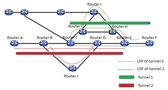
· LSP—A label switched path (LSP) is a path through an MPLS network, set up by a signaling protocol, such as LDP, RSVP TE, BGP or CR-LDP. The path is set up based on criteria in the forwarding equivalence class (FEC), a term used in MPLS to describe a set of packets with similar or identical characteristics which can be forwarded the same way so they can be bound to the same MPLS label.
· MPLS TE tunnel—Reroute and transmission over multiple paths might involve multiple LSP tunnels. A set of such LSP tunnels is called a traffic engineered tunnel (TE tunnel).
In Figure 34, the LSP along Router B —> Router J —> Router D is a static LSP. It is created to bypass Router C, which might be a congested node. A static LSP is created along fixed route with fixed nodes, so that the traffic is forced to go along Router B —> Router J —> Router D.
The tunnel from Router C to Router F is a dynamic tunnel created by using dynamic signaling protocol RSVP-TE. Between Router C and Router F there are several LSPs. Unlike traditional networks that perform routing based on only cost values, MPLS TE calculates the shortest path to a node based on cost values and constraints on the LSP with respect to bandwidth, color, setup/hold priority, explicit path, other constraints, and TEDB. LSP along Router G —> Router I —> Router H is a dynamic LSP. It is created to protect the link between Router G and Router H so that after the link between Router G and Router H breaks down, traffic can travel along Router G —> Router I —> Router H.
In Figure 34, tunnel 1 is a static tunnel and tunnel 2 is a dynamic tunnel.
MPLS TE implementation
MPLS TE mainly accomplishes the following functions:
· Static Constraint-based Routed LSP (CR-LSP) processing to create and remove static CR-LSPs. The bandwidth of a static CR-LSP must be configured manually.
· Dynamic CR-LSP processing to handle three types of CR-LSPs: basic CR-LSPs, backup CR-LSPs and fast rerouted CR-LSPs.
Static CR-LSP processing is simple, while dynamic CR-LSP processing involves four phases: advertising TE attributes, calculating paths, establishing paths, and forwarding packets.
Advertising TE attributes
MPLS TE must be aware of dynamic TE attributes of each link on the network. This is achieved by extending link state-based IGPs such as OSPF and IS-IS.
OSPF and IS-IS extensions add to link states such TE attributes as link bandwidth and color. Maximum reservable link bandwidth and non-reserved bandwidth with a particular priority are most important.
Each node collects the TE attributes of all links on all routers within the local area or at the same level to build up a TE database (TEDB).
Calculating paths
Link state-based routing protocols use Shortest Path First (SPF) to calculate the shortest path to each network node.
In MPLS TE, the Constraint-based Shortest Path First (CSPF) algorithm is used to calculate the shortest, TE compliant path to a node. It is derived from SPF and makes calculation based on two conditions:
· Constraints on the LSP to be set up with respect to bandwidth, color, setup/hold priority, explicit path and other constraints. They are configured at the LSP ingress.
· TE database (TEDB)
CSPF first prunes TE attribute incompliant links from the TEDB, and then performs SPF calculation to identify the shortest path to an LSP egress.
Establishing paths
The head-end node establishes a tunnel to the tail-end node using a signaling protocol called RSVP TE. It can carry constraints such as LSP bandwidth, some explicit route information, and color.
Forwarding packets
Packets are forwarded over established tunnels.
MPLS TE Management workflow
To use MPLS TE Management effectively in your network environment, it is helpful to understand the recommended workflow, as shown in Figure 35.
Figure 35 MPLS TE Management workflow
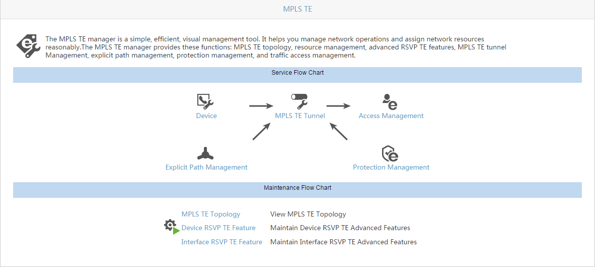
Workflow tasks are summarized as follows:
1. Import and configure network devices, such as routers, switches, and other devices that support MPLS TE. To ensure that a device can be imported to the MPLS TE system properly, perform the following operations on the device:
a. Configure the loopback address and the LSR ID IP address.
b. Configure a static route or an IGP protocol, such as OSPF, to make sure that the device is reachable on the network and the LSR ID of the device is advertised to the network through the routing protocol.
c. Make sure that MPLS TE basic capabilities have been enabled on devices. Commands for enabling MPLS TE basic capabilities differ from device to device, for detailed information about how to enable MPLS TE basic capabilities on your device, see the configuration guide of the device.
2. Adjust device configurations, such as the device CR-LSP arbitrage policy and the traffic forwarding parameters.
3. Configure explicit path (optional). This step is not necessary in static CR-LSP tunnel configuration, and is optional in dynamic tunnel configuration. An explicit path consists of a series of nodes and is used to restrict the path that a tunnel is to pass. When configuring a tunnel, you can bind a configured explicit path.
4. Create a tunnel. You can configure an MPLS TE tunnel using static CR-LSP, a dynamic signaling protocol RSVP TE or CR-LDP. Configuring an MPLS TE tunnel through a static CR-LSP requires no tunnel constraints and involves no TE extension of any IGP or CSPF calculation. Configuring a tunnel through a dynamic signaling protocol is more complicated. The dynamic signaling protocol can dynamically adjust the path of the TE tunnel according to the network performance, and supports advanced features such as backup and Fast Reroute (FRR).
5. Configure protection (optional). MPLS TE Management allows you to configure a backup path and FRR protection for a network node or link. After the node or link fails, traffic is rerouted to the backup path for forwarding.
6. Configure traffic access. Data can be forwarded along the tunnel only after you introduce the traffic to the tunnel.
7. View the MPLS TE network topology (optional). You can zoom in or out of the topology view, display the vertical view of the topology, display the TE link information, and filter links by tunnel and by administrative group.
Configuring traffic engineering in MPLS TE Management
MPLS TE Management works with the devices that form the basis of your network infrastructure. After you install and deploy MPLS TE Management through the H3C Intelligent Deployment Monitoring Agent, you can launch IMC in your browser, access MPLS TE Management, and work with supported devices.
You must make sure that the devices have been imported into IMC basic platform and that MPLS and MPLS TE basic capabilities are enabled on your devices before you can manage your TE networks using MPLS TE Management. The configuration instructions for enabling MPLS and MPLS TE basic capabilities might differ from device to device. For detailed configuration instructions, see the configuration guide of your device.
Configuring MPLS basic capabilities
Before you configure MPLS basic capabilities, complete the following tasks:
· Configure link layer protocols to ensure the connectivity at the link layer.
· Assign IP addresses to interfaces, making all neighboring nodes reachable at the network layer.
· Configure static routes or an IGP protocol, ensuring that LSRs can communicate with each other at the network layer.
Configuring MPLS TE basic capabilities
After configuring the basic capabilities, you must make additional configurations in order to use MPLS TE depending on the actual requirements.
Configuration prerequisites
Before you configure MPLS TE basic capabilities, do the following:
· Configure Static Routing or IGPs to make sure all LSRs are reachable.
· Configure MPLS basic capabilities.
Managing devices
With the Device Management function, as shown in Figure 36, you can import MPLS TE devices, synchronize and query for imported devices, configure the CR-LSP arbitrage policy, traffic forwarding parameters, Fast Reroute (FRR) scanning intervals, and automatically adjust bandwidth for the imported devices.
Figure 36 Device Management page
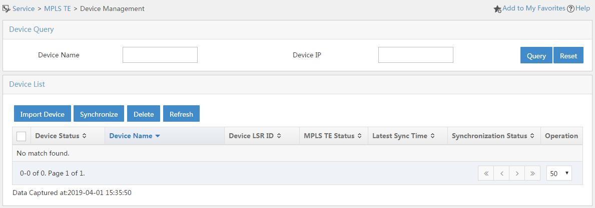
Importing devices into MPLS TE Management
To work with MPLS TE devices in MPLS TE Management, first import them to the IMC basic platform using the device auto-discovery function provided by the IMC basic platform, after that, manually import them into MPLS TE Management using the MPLS TE Management Import function.
Device auto-discovery
When you first install and deploy IMC, you can access the Auto Discovery command from the Resource menu to find the supported devices on your network.
If you install and deploy MPLS TE Management before running Resource > Auto Discovery, supported devices are discovered and shown in the main IMC device list. Then you can import them manually into MPLS TE. However, if you install and deploy MPLS TE Management after running Auto Discovery, import supported devices into MPLS TE Management as a separate step. You can only import devices that support MPLS TE into MPLS TE Management.
To ensure that a device can be imported to the MPLS TE system properly, perform the following operations on the device:
· Configure the loopback address and the LSR ID IP address.
· Configure a static route or an IGP protocol, such as OSPF, to make sure that the device is reachable on the network and the LSR ID of the device is advertised to the network through the routing protocol.
· Make sure that the MPLS TE basic capabilities are enabled on your devices.
Import function
When you install and deploy MPLS TE Management after having installed and deployed IMC, devices are not automatically imported into the MPLS TE Management device list. In this case, you can use the MPLS TE Management Import function to populate the device list.
To import a device into MPLS TE Management:
1. Click Service > MPLS TE Manager at the top of the IMC main page.
2. Click Resource Mng > Device Mng in the left navigation tree. The Device Management screen is displayed, as shown in Figure 37.
Figure 37 Device Management screen
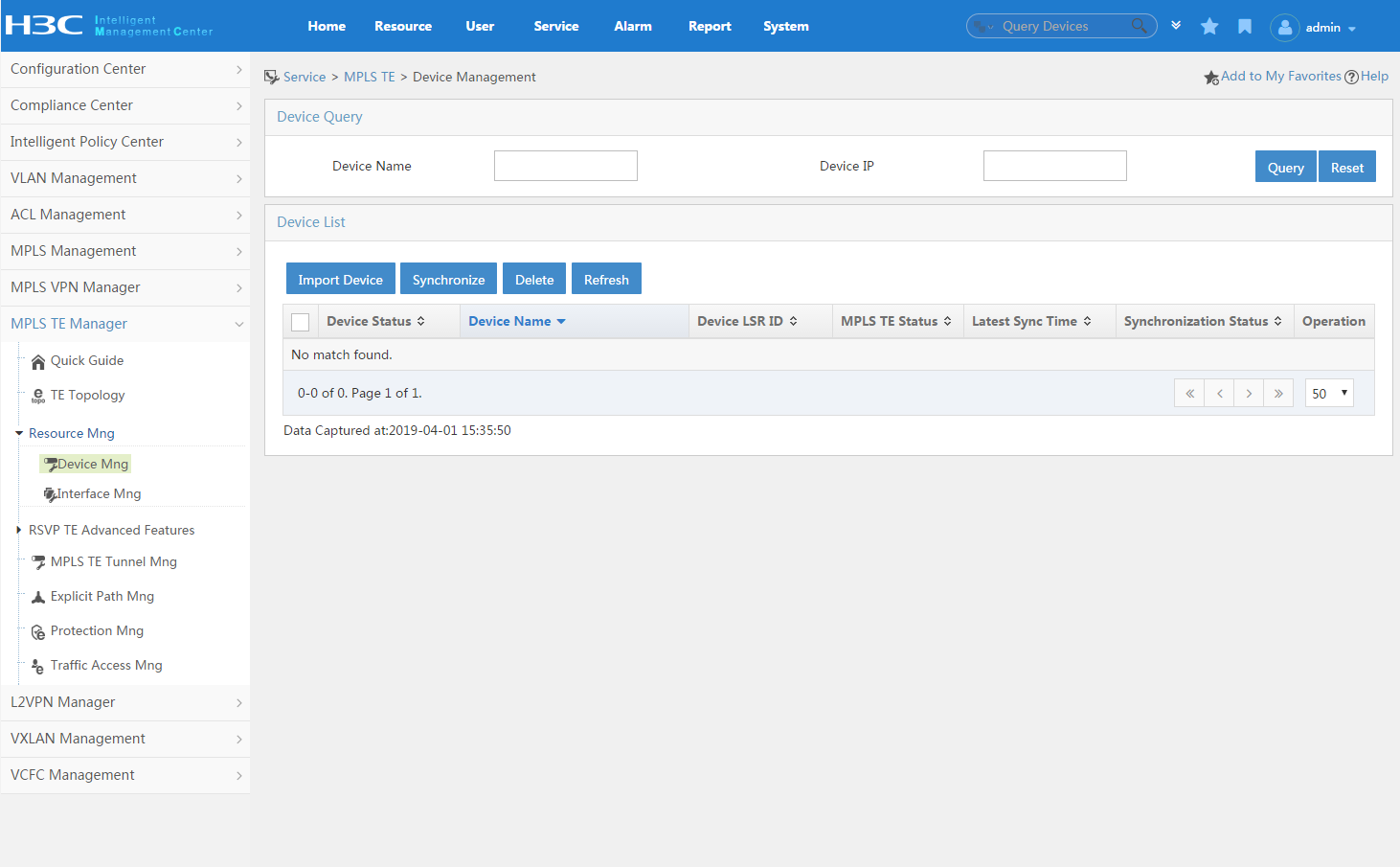
3. In the Device List section of the page, click Import Device > Select Device. The Select Devices screen is displayed, as shown in Figure 38.
Figure 38 Select Devices screen
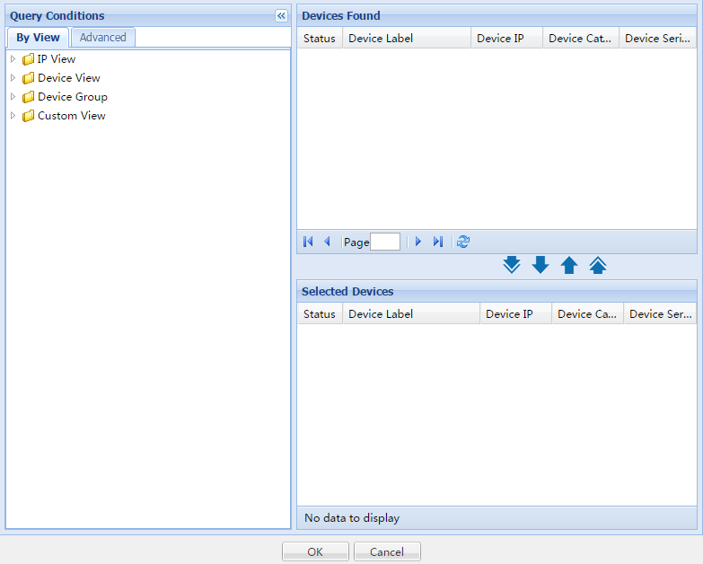
4. Specify the devices that you want to import.
· To specify a range of devices by IP address,
select IP View in the left panel. In the Devices Found panel, select a range of IP
addresses and click the Add
selected icon ![]() to copy the devices to the Selected Devices panel. Alternatively,
select the Add all icon
to copy the devices to the Selected Devices panel. Alternatively,
select the Add all icon ![]() to copy all devices to the Selected Devices panel.
to copy all devices to the Selected Devices panel.
· To specify devices, select Device View in
the left panel. In the Devices Found panel, select a range of devices and click
the Add selected icon ![]() to copy the devices to the Selected Devices panel. Alternatively,
select the Add all icon
to copy the devices to the Selected Devices panel. Alternatively,
select the Add all icon ![]() to copy all devices to the Selected Devices panel.
to copy all devices to the Selected Devices panel.
5. After all devices are displayed correctly in the Selected Devices panel, click OK to return to the Import Device page.
6. Click OK to display the import result page.
7. Click Result to return to the Device Management page to view the imported devices.
|
|
NOTE: Only devices that support MPLS TE are imported to the MPLS TE Management. These include many H3C routers and switches. |
Querying for a device
Over time, the device list can grow, making it more difficult to find a device at a glance. The Query capability enables you to search for devices by device name or device IP address. Fuzzy matching is supported, allowing you to display a partial or complete string for the device name or device IP address.
1. Click Service > MPLS TE Manager > Resource Mng > Device Mng.
2. In the Device Query section of the page, enter all or part of the entire device name or IP address/mask.
3. Click the Query button.
The device list is narrowed to the devices that meet the search criteria.
4. To clear the search criteria, click the Reset button.
Synchronizing devices
Synchronizing devices assures you that the configuration information of a device you are viewing in the Device List section of the MPLS TE Management has been synchronized with the latest configuration on the device. By synchronizing devices, the system updates the configuration of the device in the MPLS TE Management system.
To synchronize one or more devices:
1. Click Service > MPLS TE Manager at the top of the IMC main page.
2. Click Resource Mng > Device Mng in the left navigation tree.
Deleting devices
You can delete one or more devices from the MPLS TE Management system.
To delete one or more devices:
1. Click Service > MPLS TE Manager at the top of the IMC main page.
2. Click Resource Mng> Device Mng in the left navigation tree.
3. In the Device List section of the page, select one or more devices that you want to delete, and then click the Delete button.
4. Click OK.
|
|
NOTE: · Deleting a device from the system also deletes the interfaces related to the device. · Devices referenced by MPLS TE tunnels cannot be deleted. |
Configuring imported devices
This function helps you configure the CR-LSP arbitrage policy, configure traffic forwarding parameters, set the FRR scanning interval, configure auto bandwidth adjustment, enable or reset auto bandwidth adjustment, and enable MPLS TE for devices that are already imported to the MPLS TE Management. You can decide which configurations to make according to real needs.
To configure an imported device:
1. Click Service > MPLS TE Manager at the top of the IMC main page.
2. Click Resource Mng > Device Mng in the left navigation tree.
3. In the Device List section of the page,
click the Operation icon ![]() on
the same line as the device that you want to configure. A list is displayed, as shown in Figure 39.
on
the same line as the device that you want to configure. A list is displayed, as shown in Figure 39.
Figure 39 List for device operation
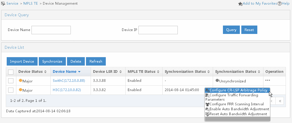
4. In the list, you can perform the following operations:
a. Select the Configure CR-LSP Arbitrage Policy option to configure the CR-LSR arbitrage policy for the device.
CR-LSP Arbitrage Policy—When CSPF is calculating the shortest path to the end of a tunnel, if multiple paths are present with the same metric value, only one is selected according to the CR-LSP arbitrage policy. CR-LSP arbitrage policy prioritizes the selection in the following order: Min Bandwidth (path with the lowest bandwidth usage ratio is preferred), Max Bandwidth (path with the highest bandwidth usage ratio is preferred), and Random (one of the remaining paths is picked at random. This rule tends to place an equal number of LSPs on each link, regardless of the available bandwidth ratio).
b. Select the Configure Traffic Forwarding Parameters option to configure the invalid link timer and the link metric type for the device. The invalid link timer starts after a link goes down. If IGP removes or modifies the link before the timer expires, CSPF is informed of the change and it then updates information about the link in TEDB and stops the timer. If IGP does not remove or modify the link before the timer expires, the state of the link in TEDB changes to up. The default value of the invalid link timer is 10 seconds and the valid range is 0 to 300 seconds. The link metric type is used when no metric type is explicitly configured for a tunnel. Link metric type can be configured as TE or IGP, and the default option is TE.
c. Select the Configure FRR Scanning Interval option to configure the interval of FRR scanning for the device. The protection provided by FRR is temporary. After a protected LSP becomes available again or a new LSP is established, traffic is switched to the protected or new LSP. After this switchover, the point of local repair (PLR), the ingress of the bypass LPS, polls available bypass tunnels for the best one at the regular interval. You can configure this regular interval here.
d. Select the Enable Auto Bandwidth Adjustment option to set the output rate sampling interval for the device. As data traffic increases or decreases due to the size and type of data being transmitted, there is therefore a general need that allows automatic bandwidth adjustment in optimizing bandwidth usage and thereby improving bandwidth efficiency. The valid range of output rate sampling interval is 1 to 604800. If the value is null then undo this function on device.
e. Select the Reset Auto Bandwidth Adjustment option to reset the auto bandwidth adjustment configuration for the device. You can reset the auto bandwidth configuration only after you have configured the auto bandwidth adjustment function.
Managing device interfaces
With the interface management function, you can manage all MPLS TE enabled interfaces of the devices imported to the MPLS TE Management system. You can query for an interface, configure an interface, query for available bandwidth, configure interface traffic parameters, and disable an enabled interface.
Querying for an interface
A device might have many interfaces, thus making the interface list quite large. Therefore, it becomes more difficult to find a specific interface. The Query capability enables you to search for an interface by device name, interface description, interface IP, and interface status.
1. Click Service > MPLS TE Manager at the top of the IMC main page.
2. Click Resource Mng> Interface Mng in the left navigation tree.
3. In the Interface Query field, enter information about the interface you want to query, and then click the Query button to display only interfaces that match the description.
4. To clear the search criteria, click the Reset button.
Configuring an interface
You can configure the MPLS TE interface information, including the management group information, maximum connection bandwidth and maximum reserved bandwidth.
Management Group—The management group is also called resource class/color. Resource class attributes are administratively assigned parameters which express some notion of "class" for resources. You can view resource class attributes as "colors" assigned to resources such that the set of resources with the same "color" conceptually belong to the same class. You can use resource class attributes to implement a variety of policies. When you apply them to links, the resource class attribute effectively becomes an aspect of the "link state" parameters.
You can use the concept of resource class attributes to implement many policies with regard to both traffic and resource oriented performance optimization. You can use resource class attributes to:
· Apply uniform policies to a set of resources that do not need to be in the same topological region.
· Specify the relative preference of sets of resources for path placement of traffic trunks.
· Explicitly restrict the placement of traffic trunks to specific subsets of resources.
· Implement generalized inclusion/exclusion policies.
· Enforce traffic locality containment policies, that is, policies that seek to contain local traffic within specific topological regions of the network.
Additionally, resource class attributes can be used for identification purposes.
Maximum reserved bandwidth—By default, a QoS policy applied in internetwork operating system (IOS) only reserves up to 75% of the available bandwidth of a link. The reason is to leave some headroom for routing protocols and other critical traffic that might not otherwise be accounted for in a QoS policy. While this is effective for low-speed links, it leaves potential for a large amount of wasted bandwidth on high-speed links. For example, on a 10 Mbps Ethernet link, only 7.5 Mbps is available for use.
You can use maximum reserved bandwidth on an MPLS TE tunnel interface to configure the bandwidth constraints of the tunnel interface by changing the default limit of 75% to something better suited to your needs. The router determines whether there is enough bandwidth to establish an MPLS TE tunnel.
1. Click Service > MPLS TE Manager at the top of the IMC main page.
2. Click Resource Mng> Interface Mng in the left navigation tree.
3. In the Interface List section of the page, select an interface that you want to configure, and then click the Configure button.
4. On the Device Interface Configuration page, enter information in the Management Group Info field, Max Connect Bandwidth(kbps) field and Max Reserve Bandwidth(kbps) field. Make sure that the maximum reserved bandwidth is less than or equal to the maximum connected bandwidth. The valid range of the management group info is 00000000 to FFFFFFFF. The valid range for max connect bandwidth and max reserve bandwidth is 1 to 32000000.
5. Click OK.
Querying for available bandwidth
You can view the available bandwidth information, which helps you with the interface configuration.
To query for available bandwidth:
1. Click Service > MPLS TE Manager at the top of the IMC main page.
2. Click Resource Mng > Interface Mng in the left navigation tree.
3. In the Interface List
section of the page, click the Operation icon ![]() on
the same line as the interface that you want to view bandwidth about. A list of
options is displayed.
on
the same line as the interface that you want to view bandwidth about. A list of
options is displayed.
4. Select the Query Available Bandwidth option to view all available bandwidth.
5. To return to the previous screen, click Back.
Configuring interface traffic parameters
To configure traffic parameters for an interface:
1. Click Service > MPLS TE Manager at the top of the IMC main page.
2. Click Resource Mng > Interface Mng in the left navigation tree.
3. In the Interface List
section of the page, click the Operation icon ![]() on
the same line as the interface that you want to configure interface traffic
parameters for. A list of options is displayed.
on
the same line as the interface that you want to configure interface traffic
parameters for. A list of options is displayed.
4. Select the Configure Interface Traffic Parameters option.
5. In the Configure Interface Traffic Parameters page, enter information in the IGP flood upper limit of bandwidth diversification (%) field and IGP flood lower limit of bandwidth diversification (%) field to configure the upper and lower thresholds for IGP to flood bandwidth changes, and enter information in the TE Metric of a Link field to assign TE metric to the link. The valid range of IGP flood upper limit of bandwidth diversification and IGP flood lower limit of bandwidth diversification is 0 to 100 and the default value is 10. The valid range of TE metric of a link is from 0 to 4294967295, and the default value is 0.
IGP flooding—After the bandwidth of links regulated by MPLS TE changes, CSPF will recalculate paths. This tends to be resource consuming as recalculation involves IGP flooding. To reduce recalculations and flood only significant changes, you can configure the following two IGP flooding thresholds in percentages so that IGP flooding is triggered only when the thresholds are reached:
· IGP flood upper limit of bandwidth diversification (%)—When the percentage of available-bandwidth increase to the maximum reservable bandwidth exceeds the threshold, the change is flooded.
· IGP flood lower limit of bandwidth diversification (%)—When the percentage of available-bandwidth decrease to the maximum reservable bandwidth exceeds the threshold, the change is flooded.
6. Click OK.
Enabling interfaces
With this function, you can enable MPLS TE on a disabled interface.
To enable MPLS TE on a disabled interface:
1. Click Service > MPLS TE Manager at the top of the IMC main page.
2. Click Resource Mng > Interface Mng in the left navigation tree.
3. In the Interface List
section of the page, click the Operation icon ![]() on
the same line as the disabled interface that you want to enable. A list of
options is displayed.
on
the same line as the disabled interface that you want to enable. A list of
options is displayed.
4. Select the Enable Interface option. This interface is enabled with MPLS TE.
Disabling interfaces
With this function, you can disable MPLS TE from an enabled interface.
To disable MPLS TE capabilities from an enabled interface:
1. Click Service > MPLS TE Manager at the top of the IMC main page.
2. Click Resource Mng > Interface Mng in the left navigation tree.
3. In the Interface List
section of the page, click the Operation icon ![]() on
the same line as the enabled interface that you want to enable. A list of
options is displayed.
on
the same line as the enabled interface that you want to enable. A list of
options is displayed.
4. Select the Disable Interface option. MPLS TE capabilities are disabled from this interface.
Advanced RSVP-TE features
RSVP and RSVP-TE
Resource Reservation Protocol (RSVP) is used for reserving resources on each node along a path. RSVP operates at the transport layer but does not participate in data transmission.
The following are features of RSVP:
· Unidirectional
· Receiver oriented. The receiver initiates resource reservation requests and is responsible for maintaining the reservation information.
· Using soft state mechanism to maintain resource reservation information.
Extended RSVP can support MPLS label distribution and allow resource reservation information to be transmitted with label bindings. This extended RSVP is called RSVP-TE, which is operating as a signaling protocol for LSP tunnel setup in MPLS TE. RSVP-TE provides many configuration options with respect to reliability, network resources, and other advanced features of MPLS TE.
Prerequisites for configuring RSVP TE advanced features
Before configuring RSVP-TE advanced features, do the following:
1. Configure MPLS basic capabilities.
2. Configure MPLS TE basic capabilities.
3. Establish an MPLS TE tunnel with RSVP-TE.
You must make sure that MPLS and MPLS TE basic capabilities are enabled on your devices before you can manage your TE networks using MPLS TE Management. The configuration instructions for enabling MPLS and MPLS TE basic capabilities might differ from device to device. For detailed configuration instructions, see the configuration guide of your device.
Querying for RSVP TE device features
Over time, the device features list can grow large, making it more difficult to find features of a device at a glance. The Query capability enables you to search for RSVP TE device features of a device by device name or device IP address/mask.
To query for RSVP TE features of a device:
1. Click Service > MPLS TE Manager at the top of the IMC main page.
2. Click RSVP TE Advanced Features > Device Features in the left navigation tree.
3. Specify part or all of the device name or IP address, and then click the Query button to display only devices that match the description.
4. To clear the query criteria, click the Reset button.
Configuring RSVP for a device
You can configure RSVP information for a device.
To configure RSVP information for a device:
1. Click Service > MPLS TE Manager at the top of the IMC main page.
2. Click RSVP TE Advanced Features > Device Features in the left navigation tree.
3. Click the Configuration
icon ![]() on the same line as the RSVP device that you want to configure. The
Configure Device RSVP page opens, as shown in Figure 40.
on the same line as the RSVP device that you want to configure. The
Configure Device RSVP page opens, as shown in Figure 40.
Figure 40 Configure Device RSVP page
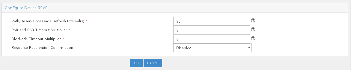
4. Enter the following parameters:
· Path/Reserve Message Refresh Interval(s)
RSVP maintains path and reservation state by periodically retransmitting two types of messages: Path message and Reserve message. These periodically retransmitted Path and Reserve messages are called refresh messages. They are sent along the path the last Path or Reserve message travels to synchronize state between RSVP neighbors and recover lost RSVP messages.
Where many RSVP sessions are present, periodically sent refresh messages become a network burden. In addition, for some delay-sensitive applications, the refresh delay for recovering lost RSVP messages might be significant. Therefore, you can set the Path/Reserve message refresh intervals to address such problems.
The valid range of Path/Reserve message refresh interval is from 10 seconds to 65535 seconds, and the default value is 30 seconds.
· PSB and RSB Timeout Multiplier
To create an LSP tunnel, the sender sends a Path message with a LABEL_REQUEST object. After receiving this Path message, the receiver assigns a label for the path and puts the label binding in the LABEL object in the returned Resv message. The LABEL_REQUEST object is stored in the path state block (PSB) on the upstream nodes, while the LABEL object is stored in the reservation state block (RSB) on the downstream nodes. The state stored in the PSB or RSB object times out and is removed after the number of consecutive non-refreshing times exceeds the PSB or RSB timeout keep-multiplier. The valid range of PSB and RSB timeout multiplier is from 3 to 255, and the default value is 3.
· Blockade Timeout Multiplier
You might sometimes want to store the resource reservation state for a reservation request that does not pass the admission control on some node. However, this should not prevent the resources reserved for the request from being used by other requests. To handle this situation, the node transits to the blockade state and a blockade state block (BSB) is created on each downstream node. When the number of non-refreshing times exceeds the blockade multiplier, the state in the BSB is removed. The default value is 4.
· Resource Reservation Confirmation
If you select Enabled from the Resource Reservation Confirmation list, you enable the RSVP confirmation feature, which is used for improving the reliability of message transfer.
Configuring device RSVP HELLO extension information
The RSVP HELLO extension is configured to detect node failures. You can use this function to detect the reachability of RSVP neighboring nodes.
To configure device RSVP HELLO extension information:
1. Click Service > MPLS TE Manager at the top of the IMC main page.
2. Click RSVP TE Advanced Features > Device Features in the left navigation tree.
3. Click the Modify icon ![]() on
the same line as the RSVP device that you want to configure. The Configure Device RSVP HELLO Extension Info page opens, as
shown in Figure 41.
on
the same line as the RSVP device that you want to configure. The Configure Device RSVP HELLO Extension Info page opens, as
shown in Figure 41.
Figure 41 Configure Device RSVP Hello Extension Info page
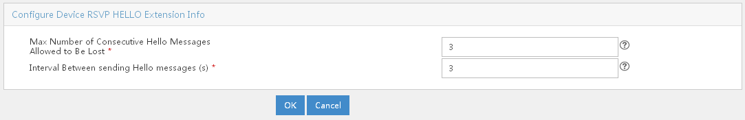
Querying for interface RSVP TE information
Over time, the RSVP TE interface features list can grow large, making it more difficult to find features of an interface at a glance. The Query capability enables you to search for RSVP TE information of an interface by its device name or device IP address.
To query for interface RSVP TE information:
1. Click Service > MPLS TE Manager at the top of the IMC main page.
2. Click RSVP TE Advanced Features > Interface Features in the left navigation tree.
3. In the Interface Features Query section of the page, enter the information about the interface, and then click the Query button to display only interfaces that match the description.
4. To clear the query criteria, click the Reset button.
|
|
NOTE: The interface you want to query for must be an MPLS TE enabled interface. |
Configuring and modifying interface RSVP attributes
To configure and modify interface RSVP attributes:
1. Click Service > MPLS TE Manager at the top of the IMC main page.
2. Click RSVP TE Advanced Features > Interface Features in the left navigation tree.
3. In the Interface Features List section of the page, select the interface that you want to configure, and then click the Configure button. The Configure Interface RSVP TE Attributes page opens, as shown in Figure 42.
Figure 42 Configure Interface RSVP TE Attributes page
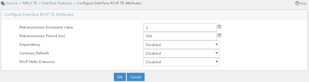
4. Configure the following parameters:
· Retransmission Increment Value and Retransmission Period (ms).
You can configure RSVP message retransmission. After the interface sends an RSVP message, it waits for acknowledgment. If no acknowledgment is received before the initial retransmission interval expires, the interface resends the message. After that, the interface resends the message at an exponentially increased retransmission interval. The valid range of retransmission increment value is from 1 to 10. If the value is null, then shut down the retransmission function on the device. The valid range of retransmission period is from 500 to 3000. If the value is null, then shut down the retransmission function on the device.
· Summary Refresh
Send summary refreshes instead of standard Path or Resv messages to refresh RSVP state information. This reduces refresh traffic and allows nodes to make faster processing. You can select Enabled from the Summary Refresh list to enable the summary refresh.
· RSVP Hello Extension
The RSVP Hello Extension attribute detects the reachability of RSVP neighboring nodes. You can select Enabled from the RSVP Hello Extension list to enable the reachability detection.
5. Click OK.
Configuring an MPLS TE tunnel using static CR-LSP
Unlike ordinary LSPs established based on routing information, CR-LSPs are established based on criteria such as bandwidth, selected path, and QoS parameters in addition to routing information. The mechanism setting up and managing constraints is called Constraint-based Routing (CR). If you want to create an MPLS TE tunnel along a fixed route with fixed nodes, you can create it using static CR-LSP. Creating MPLS TE tunnels using static CR-LSPs does not involve configuration of tunnel constraints or the issue of IGP TE extension or CSPF.
Despite its ease of configuration, the application of MPLS TE tunnels using static CR-LSPs is restricted because they cannot dynamically adapt to network changes.
Configuration prerequisites
Before making the configuration, do the following:
· Configure Static Routing or an IGP protocol to make sure that all LSRs are reachable.
· Configure MPLS basic capabilities.
· Configure MPLS TE basic capabilities.
You must make sure that MPLS and MPLS TE basic capabilities are enabled on your devices before you can manage your TE networks using MPLS TE Management. The configuration instructions for enabling MPLS and MPLS TE basic capabilities might differ from device to device. For detailed configuration instructions, see the configuration guide of your device.
Configuration procedure
To configure an MPLS TE tunnel using static CR-LSP:
1. Import devices into MPLS TE Management.
2. Click Service > MPLS TE Manager > MPLS TE Tunnel Mng at the top of the IMC main page.
3. In the MPLS TE Tunnel Query List section, click Add.
The Configure Static CR-LSP page opens, as shown in Figure 43.
Figure 43 Configure Static CR-LSP page
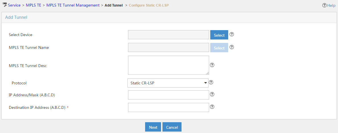
4. Specify the configuration information for the static CR-LSP.
a. Select the ingress device for the MPLS TE tunnel. Click Select next to Select Device. On the Select Device page, specify part or the entire name of the ingress device, and then click Query. Devices that match the description appear in the Device Query List section of the page. Select the ingress device, and then click OK.
b. On the Configure Static CR-LSP page, click Select next to MPLS TE Tunnel Name. Enter the name of the tunnel, and then click OK.
c. Select Static CR-LSP from the Protocol list.
d. Enter the loopback address of the egress device in the field of Destination IP Address (A.B.C.D), and then click Next.
5. In the Configure Static CR-LSP page, click Add.
The Add Static CR-LSP Node screen with Ingress selected as the role is displayed, as shown in Figure 44.
Figure 44 Add Static CR-LSP Node screen with Ingress selected as the role
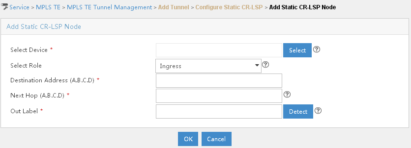
6. Add an ingress device node.
a. Click Select next to Select Device. In the Select Device page, specify part or the entire name of the ingress device, and then click Query. Devices that match the description appear in the Device Query List section of the page. Select the ingress device, and then click OK.
b. Select Ingress from the Select Role list.
c. In the Destination Address (A.B.C.D) field, enter the loopback address of the egress device.
d. In the Next Hop (A.B.C.D) field, enter the IP address of your next hop.
e. Next to Out Label, enter the out label value, and then click Detect to see if this value is available.
f. Click OK. The information of the ingress device is displayed in the Configure Static CR-LSP section of the page.
7. Add a transit device node.
a. In the Configure Static CR-LSP section of the page, click Add.
The Add Static CR-LSP Node screen with Transit selected as the role is displayed, as shown in Figure 45.
Figure 45 Add Static CR-LSP Node screen with Transit selected as the role
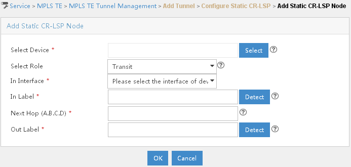
b. Click Select next to Select Device. In the Select Device page, specify part or the entire name of the transit device that is immediately connected to the ingress device, and then click Query. Devices that match the description appear in the Device Query List section of the page. Select the transit device, and then click OK.
c. Select Transit from the Select Role list. The In Interface field is populated with the information of the interface connecting to the ingress device.
d. In the In Label field, enter the in label value, and then click Detect to see if this value is available. Make sure that the in label value is the same as the out label value of the previous node.
e. In the Next Hop (A.B.C.D) field, enter the IP address of the next hop.
f. In the Out Label field, enter the out label value of the transit device, and then click Detect to see if this value is available.
g. Click OK. The information of the transit device is displayed in the Configure Static CR-LSP section of the page.
8. Add an egress device node.
a. In the Configure Static CR-LSP section of the page, click Add.
The Add Static CR-LSP Node screen with Egress selected as the role is displayed, as shown in Figure 46.
Figure 46 Add Static CR-LSP Node screen with Egress selected as the role
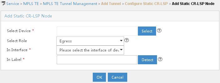
b. Click Select next to Select Device. In the Select Device page, specify part or the entire name of the egress device, and then click Query. Devices that match the description appear in the Device Query List section of the page. Select the egress device, and then click OK.
c. Select Egress from the Select Role list. The In Interface field is populated with the information of the interface connecting to the transit device.
d. In the In Label field, enter the in label value, and then select Detect to see if this value is available. Make sure that the in label value is the same as the out label value of the previous node.
e. Click OK. The information of the egress device is displayed in the Configure Static CR-LSP section of the page.
9. A complete LSP is established. Click Finish.
Managing static CR-LSP nodes
You can move, modify and delete a static CR-LSP node that you have added. By moving static CR-LSP nodes you change the position of these nodes on an LSP route.
To move a static CR-LSP node record:
1. Click Service > MPLS TE Manager > MPLS TE Tunnel Mng at the top of the IMC main page.
2. Click the Modify icon ![]() to modify the
tunnel configuration.
to modify the
tunnel configuration.
3. Click Next to display the Configure Static CR-LSP page.
4. In the Configure Static CR-LSP section of the page, select the node that you want to move.
5. Click the Upwards button or the Downwards button to move the node record up or down in the node list.
To modify a static CR-LSP node that you have added:
1. Click Service > MPLS TE Manager > MPLS TE Tunnel Mng at the top of the IMC main page.
2. In the Configure Static
CR-LSP section of the page, click the Modify
icon ![]() to modify the basic information of a node.
to modify the basic information of a node.
To delete a static CR-LSP node that you have added:
1. Click Service > MPLS TE Manager > MPLS TE Tunnel Mng at the top of the IMC main page.
2. In the Configure Static
CR-LSP section of the page, click the Delete
icon ![]() to delete the node.
to delete the node.
Configuring an MPLS TE tunnel using dynamic signaling protocol
Dynamic signaling protocol allows you to create an MPLS TE tunnel that can adapt to network changes and implement redundancy, FRR, and other advanced features. Unlike the MPLS TE tunnel created using static CR-LSP, the nodes along the tunnel created using dynamic signaling protocol are not necessarily fixed. However, if you want to specify certain nodes for your tunnel to traverse, you can specify them in an explicit path.
The following describes how to create an MPLS TE tunnel with a dynamic signaling protocol:
· Configure MPLS TE properties for links and advertise them through IGP TE extension to form a TEDB.
· Configure tunnel constraints.
· Use the CSPF algorithm to calculate a preferred path based on the TEDB and tunnel constraints.
· Establish the path using the signaling protocol RSVP-TE.
|
|
NOTE: To form a TEDB, you must configure the IGP TE extension for the nodes on the network to send TE LSAs. If the IGP TE extension is not configured, the CR-LSP is created based on IGP routing rather than computed by CSPF. |
Configuration prerequisites
Before making the configuration, do the following:
· Configure Static Routing or an IGP protocol to make sure that all LSRs are reachable.
· Configure MPLS basic capabilities.
· Configure MPLS TE basic capabilities.
You must make sure that MPLS and MPLS TE basic capabilities are enabled on your devices before you can manage your TE networks using MPLS TE Management. The configuration instructions for enabling MPLS and MPLS TE basic capabilities might differ from device to device. For detailed configuration instructions, see the configuration guide of your device.
Configuring an MPLS TE explicit path
An explicit path is a set of nodes. You can create an explicit path for an MPLS TE tunnel by specifying the nodes for the tunnel to traverse. Configuring an explicit path is not necessary in static CR-LSP tunnel configuration, and is optional in dynamic tunnel configuration.
To configure an MPLS TE explicit path:
1. Click Service > MPLS TE Manager > Explicit Path Mng at the top of the IMC main page.
2. In the Explicit Path List section of the page, click Add.
The Add Explicit Path page opens, as shown in Figure 47.
Figure 47 Add Explicit Path page
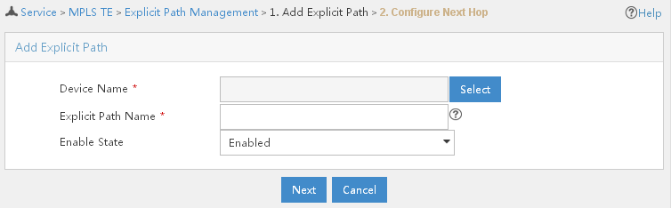
4. In the Explicit Path Name field, enter the name of the explicit path.
5. Select Enabled from the Enable State list.
7. On the Next Hop Info List page, click Add.
The Next Hop Info page opens, as shown in Figure 48.
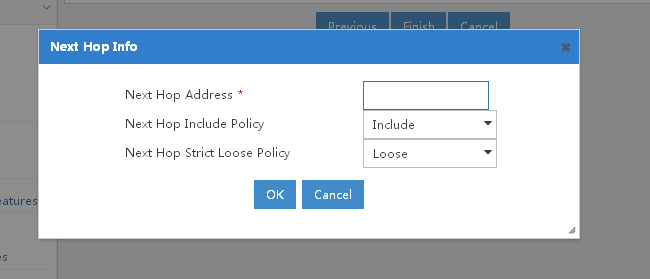
8. In the Next Hop Address field, enter the IP address of your next hop.
9. Select either Include or Exclude from the Next Hop Include Policy list. If you select the Include option, the path traverses your next hop. If you select the Exclude option, the path bypasses your next hop.
10. Select Strict or Loose from the Next Hop Strict Loose Policy list. The Strict option means two nodes are directly connected, and the Loose option means the two nodes have other devices in between. If you select the Strict option, the next hop is directly connected to its previous hop. If you select the Loose option, you allow devices to exist between the next hop and its previous hop.
11. Click OK. Information about your next hop is displayed in the Next Hop Info List section of the page. You can add more hops in the same way.
12. If you want to move a node that you already added, click the radio button in front of the node, and then click the Upwards button or the Downwards button to move the node upwards or downwards.
13. When all hops needed are added, click Finish. The explicit path is created and is displayed in the Explicit Path List section of the Explicit Path Management page.
Managing an explicit path
You can query, add, delete, and modify explicit paths that you have created. You can only modify unbound explicit paths. Unbound explicit paths are not referred by tunnels.
Over time, the explicit path list can grow large, making it more difficult to find an explicit path at a glance. The Query capability enables you to search for explicit paths by explicit path name, its device name, device LSR ID, enable state, and binding state.
To query for an explicit path:
1. Click Service > MPLS TE Manager > Explicit Path Mng at the top of the IMC main page.
2. In the Explicit Path Query section of the page, enter the query criteria.
3. Click Query. All explicit paths that match the query criteria display in the Explicit Path List section of the page.
4. To clear the query criteria and display all explicit paths, click Reset.
1. Click Service > MPLS TE Manager > Explicit Path Mng at the top of the IMC main page.
2. In the Explicit Path
List section of the page, click the Modify
icon ![]() of an unbound explicit path to display the explicit path
configuration page.
of an unbound explicit path to display the explicit path
configuration page.
3. Modify the parameters.
|
|
NOTE: You can only modify unbound explicit paths. You cannot modify the device name or the explicit path name. |
To delete one or more explicit paths:
1. Click Service > MPLS TE Manager > Explicit path Mng at the top of the IMC main page.
2. In the Explicit Path List section of the page, select one or more explicit paths, and then click Delete.
3. Click OK.
|
|
NOTE: Explicit paths that are in Bound state cannot be deleted. |
Configuring a dynamic MPLS TE tunnel
To configure a dynamic MPLS TE tunnel:
1. Click Service > MPLS TE Manager > MPLS TE Tunnel Mng at the top of the IMC main page.
2. In the MPLS TE Tunnel Query List section of the page, click Add.
The Add Tunnel page opens, as shown in Figure 49.
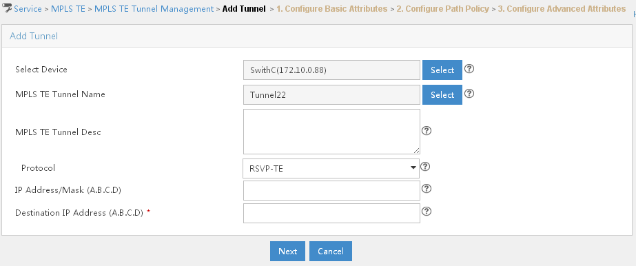
3. Specify the configuration information for the dynamic MPLS TE tunnel.
a. Click Select next to Select Device, enter part or the entire name of the ingress device, and then click Query. All devices that match the description appear in the Device Query List section of the page. Select the ingress device, and then click OK.
b. Click Select next to MPLS TE Tunnel Name, specify the tunnel name, and then click OK.
c. Select RSVP-TE from the Protocol list.
d. In the Destination IP Address (A.B.C.D) field, enter the loopback address of the egress device, and then click Next.
The Configure Basic Attributes page opens, as shown in Figure 50.
Figure 50 Configure Basic Attributes page
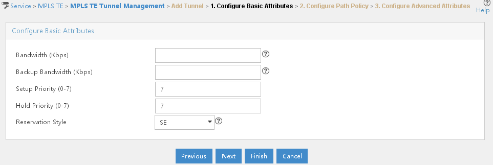
e. Configure the parameters on this page.
Bandwidth (Kbps) and Backup Bandwidth (Kbps)—If one of the two parameters is configured, the other must be also configured, and the backup bandwidth must be greater than or equal to the bandwidth. The valid range of bandwidth and backup bandwidth is from 1 to 32000000.
Setup Priority (0–7) and Hold Priority (0–7)—CR-LDP signals the resources required by a path on each hop of the route. If a route with sufficient resources cannot be found, existing paths can be rerouted to reallocate resources to the new path. This is called path preemption. Two priorities, setup priority and hold priority, are assigned to paths for making a preemption decision. Both setup and hold priorities range from 0 to 7, with a lower number indicating a higher priority.
For a new path to preempt an existing path, the setup priority of the new path must be greater than the hold priority of the existing path. To initiate preemption, the Resv message of RSVP-TE is sent.
To avoid flapping caused by improper preemptions between CR-LSPs, the setup priority of a CR-LSP should not be set higher than its hold priority.
Reservation Style—Each LSP set up using RSVP-TE is assigned a resource reservation style. During an RSVP session, the receiver decides which reservation style can be used for this session and which LSPs can be used.
Two reservation styles are available:
· Fixed-filter style (FF)—Where resources are reserved for individual senders and cannot be shared among senders on the same session.
· Shared-explicit style (SE)—Where resources are reserved for senders on the same session and shared among them.
f. Click Next.
The Configure Path Policy page opens, as shown in Figure 51.
Figure 51 Configure Path Policy page

g. Configure the parameters.
Affinity (0–FFFFFFFF) and Affinity Mask (0–FFFFFFFF):
The affinity attribute of an MPLS TE tunnel identifies the properties of the links that the tunnel can use. Together with the link administrative group, it decides which links the MPLS TE tunnel can use. This is done by ANDing the 32-bit affinity attribute with the 32-bit link administrative group attribute. When doing that, a 32-bit mask is used. The affinity bits corresponding to the 1s in the mask are "do care" bits which must be considered while those corresponding to the 0s in the mask are "don't care" bits.
For a link to be used by a TE tunnel, at least one considered affinity bit and its corresponding administrative group bit must be set to 1.
Suppose the affinity of an MPLS TE tunnel is 0xFFFFFFFF and the mask is 0x0000FFFF. For a link to be used by the tunnel, the leftmost 16 bits of its administrative group attribute can be 0s or 1s, but at least one of the rest bits must be 1.
The affinity of an MPLS TE tunnel is configured at the first node on the tunnel, and then signaled to the rest nodes through CR-LDP or RSVP-TE.
|
|
NOTE: The associations between administrative groups and affinities can vary by vendor. To ensure the successful establishment of a tunnel between two devices of different vendors, correctly configure their respective administrative groups and affinities according to their configuration guides. |
h. If you want the tunnel to refer to an explicit path that you have configured, click Select next to Explicit Path, enter part or the entire name of the explicit path, and then click Query. Explicit paths matching this description appear in the Explicit Path Query List section of the page. Select the explicit path you want, and then click OK.
i. Click Next. You are directed to the Configure Advanced Attributes page where you can see the following parameters:
Metric Type—Specify the metric type to use when no metric type is explicitly configured for a tunnel. You can select TE or IGP. TE metrics of links are used by default.
When Multiprotocol Label Switching TE is configured in a network, the IGP floods two metrics for every link: normal IGP (OSPF or IS-IS) link metric and TE link metric.
The IGP uses the IGP link metric in the normal way to compute routes for destination networks, and MPLS TE used the TE link metric to calculate and verify paths for TE tunnels. You can specify the path calculation for a given tunnel based on either of these metrics.
You can configure the TE link metrics so that they represent the needs of a particular application, for example, the TE link metrics can be configured to represent link transmission delay.
When TE tunnels are used to carry two types of traffic, you can tailor tunnel path selection to the requirements of each type of traffic. For example, suppose certain tunnels are to carry voice traffic (which requires low delay) and other tunnels are to carry data. You can use the TE link metric to represent link delay and do the following:
· Configure tunnels that carry voice to use the TE link metric set to represent link delay for path calculation.
· Configure tunnels that carry data to use the IGP metric for path calculation.
Unless explicitly configured, the TE link metric for a given link is the IGP link metric. When the TE link metric is used to represent a link property that is different from cost/distance, you must configure every network link that can be used for TE tunnels with a TE link metric that represents that property. Failure to do so might cause tunnels to use unexpected paths.
Forwarding Type—You can select the traffic flow type of the tunnel. It limits the usage of the tunnel. Values include ACL, VPN Instance and No Limit.
Loop Check—You can check if a loop exists.
Tunnel Rebuild Times—You can configure the system to attempt setting up a tunnel multiple times until it is established successfully or until the number of attempts reaches the upper limit. The valid range is from 10 to 4294967295.
Tunnel Rebuild interval(s)—You can configure the interval at which the tunnel is rebuilt. The valid range is from 1 to 4294967295.
CSPF Method—You can configure the arbitrage policy of the current tunnel, which is used for path calculation.
Route Fixing—If a route is fixed, the path information cannot be changed.
Tunnel Reoptimization—Dynamic CR-LSP optimization involves periodic calculation of paths that traffic trunks should traverse. If a better route is found for an existing CR-LSP, a new CR-LSP is established to replace the old one, and services are switched to the new CR-LSP. You can enable reoptimization for the MPLS TE tunnel.
Auto Bandwidth Adjustment—As data traffic increases or decreases due to the size and type of data being transmitted, you can enable the Auto Bandwidth Adjustment functionality to optimize bandwidth usage and thereby improves bandwidth efficiency.
Auto Bandwidth Adjustment Lower Threshold (Kbps)—The valid range is 1 to 32000000.
Bandwidth Collection Lower Threshold (Kbps)—After the bandwidth of links regulated by MPLS TE changes, CSPF will recalculate paths. This tends to be resource consuming as recalculation involves IGP flooding. To reduce recalculations and flood only significant changes, you can configure the bandwidth collection lower threshold. The valid range is 1 to 32000000.
j. Configure the parameters, and then click OK. This tunnel is displayed in the MPLS TE Tunnel Query List section of the page.
Managing MPLS TE tunnels
You can query, delete, refresh, modify, and view the network topology of an MPLS TE tunnel that you have created. You can also view detailed information about the ingress device and the MPLS TE tunnel.
Querying for an MPLS TE tunnel
Over time, the MPLS TE Tunnel query list can grow large, making it more difficult for you to find an MPLS TE tunnel at a glance. The Query capability enables you to search for MPLS TE tunnels by query type and its corresponding value.
To query for an MPLS TE tunnel:
1. Click Service > MPLS TE Manager > MPLS TE Tunnel Mng at the top of the IMC main page.
2. In the MPLS TE Tunnel Query section of the page, select Tunnel Name, Protocol or Tunnel Status from the Query Type list, specify the corresponding value in the Value field, and then click Query.
MPLS TE tunnels that match these descriptions appear in the MPLS TE Tunnel Query List section of the page.
Deleting an MPLS TE tunnel
1. Query for the MPLS TE tunnel that you want to delete.
2. In the MPLS TE Tunnel Query List section of the page, mark the check box on the same line as the MPLS TE tunnel that you want to delete, and then click the Delete button.
3. Click OK.
Modifying an MPLS TE tunnel
1. Query for the MPLS TE tunnel that you want to modify.
2. In the MPLS TE Tunnel
Query List section of the page, click the Modify
icon ![]() on the
same line as the tunnel that you want to modify.
on the
same line as the tunnel that you want to modify.
Viewing the network topology of an MPLS TE tunnel
To view the network topology of an MPLS TE tunnel:
1. Query for the MPLS TE tunnel of which you want to view the network topology.
2. In the MPLS TE Tunnel
Query List section of the page, click the Topology
icon ![]() on the same line as the tunnel for which you want to view the
network topology.
on the same line as the tunnel for which you want to view the
network topology.
Viewing detailed information about the ingress device of an MPLS TE tunnel
To view detailed information about the ingress device of an MPLS TE tunnel:
1. Query for the MPLS TE tunnel that uses the ingress device you are interested in.
2. In the MPLS TE Tunnel Query List section of the page, click the name of the ingress device under the Device Name column.
Viewing detailed information about the MPLS TE tunnel
To view detailed information about the MPLS TE tunnel:
1. Query for the MPLS TE tunnel that uses the ingress device you are interested in.
2. In the MPLS TE Tunnel Query List section of the page, click the name of the MPLS TE tunnel under the MPLS TE Tunnel Name column.
Configuring traffic access
After you have created a TE tunnel and have it operational, you should make sure that traffic is introduced to the tunnel so that data can be forwarded along the tunnel. You can enable the TE tunnel to forward traffic in three ways: Static Routing, IGP Shortcut, and Forwarding Adjacency.
Configuring traffic access procedure
1. Click Service > MPLS TE Manager > Traffic Access Mng at the top of the IMC main page.
2. In the Access Traffic List section of the page, click Add.
The Traffic Access Type Selection page opens, as shown in Figure 52.
Figure 52 Traffic Access Type Selection page
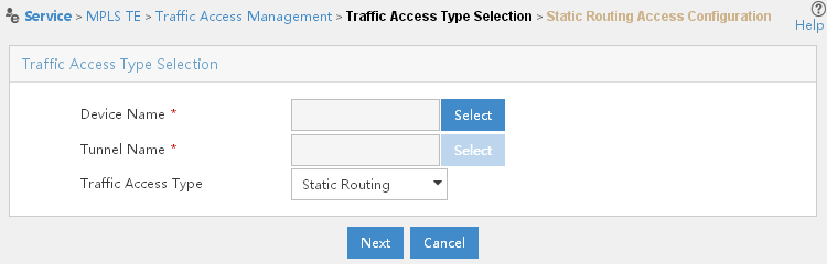
3. Click Select next to Device Name, enter part or the entire name of the ingress device and click the Query button. Devices matching this description appear in the Device Query List section of the page. Select the ingress device, and then click OK.
4. Click Select next to Tunnel Name, enter part or the entire name of the tunnel that you want traffic to be introduced to in the Tunnel Name field, and then click Query. Tunnels matching this description appear in the Tunnel Info List section of the page. Select the tunnel you want, and then click OK.
5. Select Static Routing, IGP Shortcut, or Forwarding Adjacency from the Traffic Access Type list, depending on how your network was set up.
Static Routing—Static Routing is not really a routing protocol. Static Routing is the process of manually entering routes into a routing table of a device via a configuration file that is loaded when the routing device starts up. As an alternative, these routes can be entered by a network administrator who configures the routes manually. Because these manually configured routes do not change after they are configured, they are called static routes. Static Routing is the simplest form of routing, but it is a manual process.
A static routed environment is best suited to a small, single-path, static network. A small network is defined as 2 to 10 networks. Single-path means that there is only a single path for packets to travel between any two endpoints on the network. Static means that the topology of the network does not change over time. You only need to manually create a route that reaches the destination through the tunnel interface.
Static Routing has disadvantages. If a router or link goes down, static routers do not sense the fault or inform other routers of the fault. Therefore it is suitable for small networks where routers or networks do not go down often enough to justify deploying a multipath topology and a routing protocol. Besides, Static Routing does not handle failures or changes in networks well. For example, if a new network is added or removed from the network, routes to the new network must be manually added or removed. If a new router is added, it must be properly configured for the routes of the network.
IGP Shortcut—Interior Gateway Protocol (IGP) shortcut is an extra step in the intra-area (or intra-level) best route selection process in OSPF or IS-IS. Without the autoroute-enabled MPLS TE tunnels, the Shortest Path First (SPF) algorithm builds the shortest path tree to compute the minimum cost to all other routers in the area, and then selects the best routes based on the minimum cost. The IGP Shortcut feature modifies the shortest path tree on the tunnel head-end LSR before the best routes are selected by inserting the MPLS TE tunnel in the SPF tree. The IGP Shortcut feature ensures that the tunnel is used to transport all the traffic from the head-end LSR to all destinations behind the tailed LSR. The path toward the tunnel tail-end LSR is replaced by a direct link (MPLS TE tunnel) in the SPF tree.
The modification of the SPF tree is local to the head-end router and does not affect the topology database or the SPF trees built by other routers. Therefore, the MPLS TE tunnel created by IGP Shortcut is not seen by other routers, which means that other routes cannot use this tunnel to compute the shortest path for routing traffic throughout the network.
Forwarding Adjacency—The Forwarding Adjacency feature allows a network administrator to handle a TE, label-switched path (LSP) tunnel as a link in an IGP network based on the SPF algorithm. A Forwarding Adjacency can be created between routers regardless of their location in the network. The routers can be located multiple hops from each other.
OSPF includes MPLS TE tunnels in the OSPF link-state database in the same way that other links appear for purposes of routing and forwarding traffic. When an MPLS TE tunnel is configured between networking devices, that link is considered a Forwarding Adjacency. You can assign a cost to the tunnel to indicate the preference of the link.
The benefit of the Forwarding Adjacency feature is that TE tunnel interfaces are advertised in the IGP network just like any other links. Routers can then use these advertisements in their IGPs to compute the SPF even if they are not the head-end of any TE tunnels. This means that routers outside of the TE domain can see the TE tunnel and use it to compute the shortest path for routing traffic throughout the network. However, using the MPLS TE Forwarding Adjacency feature increases the size of the IGP database by advertising a TE tunnel as a link. Moreover, MPLS TE Forwarding Adjacency tunnels must be configured bidirectionally.
IGP shortcut and Forwarding Adjacency—IGP Shortcut and Forwarding Adjacency are different. In the Forwarding Adjacency approach, routes with TE tunnel interfaces as outgoing interfaces are advertised to neighboring routers but not in the IGP Shortcut approach. Therefore, TE tunnels are visible to other routers in the Forwarding Adjacency approach but not in the IGP Shortcut approach.
Figure 53 IGP Shortcut and Forwarding Adjacency
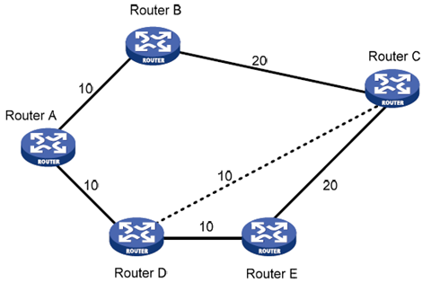
As shown in Figure 53, a TE tunnel is present between Router D and Router C. With IGP Shortcut enabled, the ingress node Router D can use this tunnel when calculating IGP routes. This tunnel, however, is invisible to Router A; therefore, Router A cannot use this tunnel to reach Router C. With Forwarding Adjacency enabled, Router A can know the presence of the TE tunnel and thus forward traffic to Router C to Router D through this tunnel.
6. If you select Static Routing for Traffic Access Type, you are directed to the Static Routing Access Configuration page, as shown in Figure 54.
Figure 54 Static Routing Access Configuration page
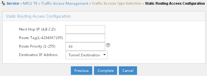
a. In the Next Hop IP (A.B.C.D) field, enter the IP address of the next hop.
b. In the Route Tag (1-4294967295) field, enter the value of the route tag.
Route Tag—Both OSPF and IS-IS allow the association of a 32-bit value called a route tag with external prefixes. You can consider route tags as a protocol extensibility feature because they enable you to arbitrarily assign some administratively meaningful value to external prefixes to associate them with some group that you define. You can then create routing policies that act on the external prefixes according to their assigned tags.
The most common application of route tags is in complex route redistribution policies. Route tags are used when it is impractical to identify prefixes using prefix lists or route filters, either because there are so many prefixes to be identified that the list would be unmanageably long, or because you are uncertain what prefixes need to be identified. You can tag prefixes at their point of origin by incoming interface, advertising neighbor, or redistribution point, for example, and then apply polices to the prefixes elsewhere in your network by identifying the tag, instead of individual prefixes.
Another application for route tags is for leaking prefixes from one IS-IS level to another, in which you want to leak some prefixes but not others. Polices can be used to tag prefixes at their origin, identifying them with administratively defined groups. Other polices can then be implemented at level boundaries that identify the prefix groups, by tags, that are to be leaked and the prefix groups that are to be suppressed.
c. In the Route Priority field, assign a value to the route priority. A lower numerical number indicates a higher priority.
d. Select Tunnel Destination or Custom IP Address in the Destination IP Address list. You can use the destination address of the tunnel or customize the address by yourself. The default value of destination IP address is 60.
7. Click Complete. The traffic access is added successfully and is displayed in the Access Traffic List section of the page.
8. If you select IGP Shortcut or Forwarding Adjacency for Traffic Access Type, you are directed to the IGP Shortcut Configuration page, as shown in Figure 55.
Figure 55 IGP Shortcut Configuration page
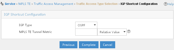
a. Select OSPF, ISIS or OSPF and ISIS from the IGP Type list.
MPLS TE must be aware of dynamic TE attributes of each link on the network. This is achieved by extending link state-based IGPs such as OSPF and IS-IS.
OSPF or IS-IS with extensions for TE is used to carry information pertaining to the link states. The extensions add to link states such TE attributes as link bandwidth, color, maximum reservable link bandwidth and non-reserved bandwidth with a particular priority. As a result, a link that does not have the requested resources (like bandwidth) is not chosen to be a part of the LSP tunnel or TE tunnel.
b. Assign a metric value, either absolute or relative, to TE tunnels for the purpose of path calculation. If it is absolute (or fixed), the metric is used for path calculation. If it is relative (or floating), the cost of the corresponding IGP path must be added to the metric before it can be used for path calculation.
An absolute metric indicates that there is no relationship to the underlying IGP cost. A relative metric is added to or subtracted from the underlying IGP shortest path cost. If you use a relative metric, the actual assigned metric value of routes is based on the IGP metric. This relative metric can be positive or negative, and is bounded by minimum and maximum allowed metric values.
For example, if you specify a relative metric of -2 for an MPLS TE tunnel, OSPF treats this tunnel as having a metric of 2 less than the shortest path metric it has calculated. The tunnel is therefore preferred over other paths to prefixes beyond the tunnel endpoint. If you specify an absolute metric of 25, and configure OSPF to enable the consideration of SPF best paths, OSPF considers this metric in its SPF calculations for traffic to the tunnel endpoint as well as beyond the endpoint. Traffic is routed via this tunnel only if the other calculated paths have higher metrics.
c. Click Complete. The traffic access is added successfully and is displayed in the Access Traffic List section of the page.
Managing traffic access
You can query, add and delete traffic access configuration. Through the traffic access configuration, you can distribute traffic to a specified tunnel.
1. Click Service > MPLS TE Manager > Traffic Access Mng at the top of the IMC main page.
2. In the Traffic Access Query section of the page, select the query type and enter the query value.
3. Click Query.
To delete traffic access configuration:
1. Click Service > MPLS TE Manager > Traffic Access Mng at the top of the IMC main page.
2. In the Access Traffic List section of the page, select the traffic access record you want to delete, and then click Delete.
3. Click OK.
Protection management
You can use the protection management function to avoid an invalid link or node, in order to avoid data loss and service interruption. You can perform protection configuration to protect a link or node, so that when the link or node fails, its traffic can travel through the backup link or node instead. The supported protection types are CR-LSP backup protection and FRR.
CR-LSP backup protection
CR-LSP backup provides end-to-end path protection for the entire LSP without time limitation. This is different from Fast Reroute (FRR) which provides quick but temporary per-link or per-node protection on an LSP.
In the same TE tunnel, the LSP used to back up a primary LSP is called a secondary LSP. When the ingress of a TE tunnel detects that the primary LSP is unavailable, it switches traffic to the secondary LSP and after the primary LSP becomes available, switches traffic back. This is how LSP path protection is achieved.
Configuring CR-LSP backup protection
Configuration prerequisites
Before you configure CR-LSP backup, complete the following tasks:
· Configure MPLS basic capabilities.
· Configure MPLS TE basic capabilities.
· Configure MPLS TE tunnels.
Make sure that MPLS and MPLS TE basic capabilities are enabled on your devices before you can manage your TE networks using MPLS TE Management. The configuration instructions for enabling MPLS and MPLS TE basic capabilities might differ from device to device. For detailed configuration instructions, see the configuration guide of your device.
|
|
NOTE: CR-LSP backup should be configured at the ingress node of a tunnel. The system routes the primary LSP and backup LSP automatically. You do not need to configure them. |
Querying for a tunnel for CR-LSP backup
To query for a tunnel for CR-LSP backup:
1. Click Service > MPLS TE Manager > Protection Mng at the top of the IMC main page.
2. In the Tunnel Query section of the page, select MPLS TE Tunnel name, Tunnel State, or Protocol from the Query Type list, specify the corresponding value in the Value field, and then click Query. Tunnels matching this description appear in the Protected Tunnel List section of the page, as shown in Figure 56.
Figure 56 Protected Tunnel List section
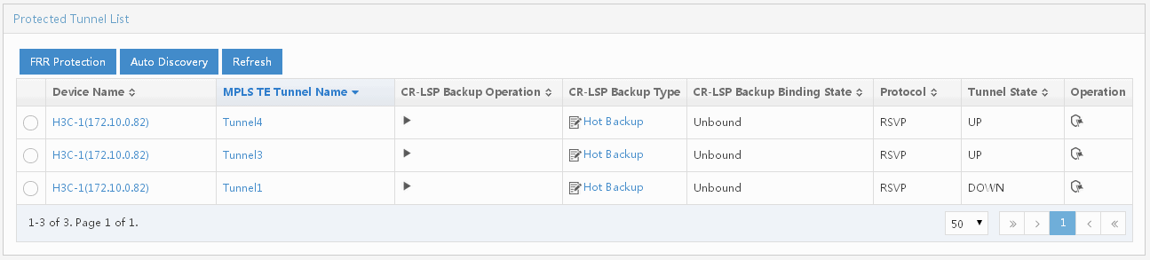
3. Find the tunnel that you want to configure
CR-LSP backup for, click Hot Backup in the CR-LSP Backup Operation column to change the CR-LSP
backup type, and then click the CR-LSP Backup Operation
icon ![]() .
.
Two approaches are available for CR-LSP backup:
· Hot backup—Where a secondary CR-LSP is created immediately after a primary CR-LSP is created. MPLS TE switches traffic to the second CR-LSP after the primary CR-LSP fails.
· Second backup—Where a secondary CR-LSP is created to take over after the primary CR-LSP fails.
FRR
Fast Reroute (FRR) provides a quick per-link or per-node protection on an LSP.
In this approach, after a link or node fails on a path, FRR comes up to reroute the path to a new link or node to bypass the failed link or node. This can happen as fast as 50 milliseconds thus minimizing data loss.
Basic concepts
The following are FRR concepts:
· Primary LSP—The protected LSP.
· Bypass LSP—An LSP used to protect the primary LSP.
· Point of local repair (PLR)—The ingress of the bypass LSP. It must be located on the primary LSP but must not be the egress.
· Merge point (MP)—The egress of the bypass LSP. It must be located on the primary LSP but must not be the ingress.
FRR link protection and node protection
FRR provides link protection and node protection for an LSP as follows:
· Link protection, where the PLR and the MP are connected through a direct link and the primary LSP traverses this link. When the link fails, traffic is switched to the bypass LSP. As shown in Figure 57, the primary LSP is Router A —> Router B —> Router C —> Router D, and the bypass LSP is Router B —> Router F —> Router C.
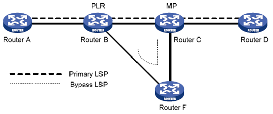
· Node protection, where the PLR and the MP are connected through a router and the primary LSP traverses this router. When the router fails, traffic is switched to the bypass LSP. As shown in Figure 58, the primary LSP is Router A —> Router B —> Router C —> Router D —> Router E, and the bypass LSP is Router B —> Router F —> Router D. Router C is the protected router.
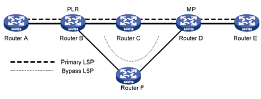
Deploying FRR
When configuring the bypass LSP, make sure that the protected link or node is not on the bypass LSP.
Because bypass LSPs are pre-established, FRR requires extra bandwidth. When network bandwidth is insufficient, use FRR for crucial interfaces or links only.
Configuring FRR
Fast Reroute (FRR) provides quick but temporary per-link or per-node local protection on an LSP.
FRR uses bypass tunnels to protect primary tunnels. As bypass tunnels are pre-established, they require extra bandwidth and are usually used to protect crucial interfaces or links only.
You can define which type of LSP can use bypass LSPs, and whether a bypass LSP provides bandwidth protection as well as the sum of protected bandwidth.
The bandwidth of a bypass LSP is to protect its primary LSPs. To guarantee that a primary LSP can always bind with the bypass LSP successfully, make sure that the bandwidth assigned to the bypass LSP is not less than the total bandwidth needed by all protected LSPs.
Normally, bypass tunnels only forward data traffic when protected primary tunnels fail. To allow a bypass tunnel to forward data traffic while protecting the primary tunnel, make sure that bypass tunnels are available with adequate bandwidth.
A bypass tunnel cannot be used for services like VPN at the same time.
Configuration prerequisites
Before you configure FRR, complete the following tasks:
· Configure IGP, ensuring that all LSRs are reachable.
· Configure MPLS basic capabilities.
· Configure MPLS TE basic capabilities.
· Establish an MPLS TE tunnel with RSVP-TE.
· Set up primary LSPs.
Make sure that MPLS and MPLS TE basic capabilities are enabled on your devices before you can manage your TE networks using MPLS TE Management. The configuration instructions for enabling MPLS and MPLS TE basic capabilities might differ from device to device. For detailed configuration instructions, see the configuration guide of your device.
1. Click Service > MPLS TE Manager > Protection Mng at the top of the IMC main page.
2. In the Protected Tunnel List section of the page, select a tunnel that you want to use as the bypass tunnel, and then click FRR Protection.
3. Select Link Protection from the Protection Type list.
4. Click Next.
5. In the Link List section of the page, select the primary tunnel that you want to protect.
6. Click Next.
7. In the Protected Tunnel List section of the page, select the bypass tunnel, and then click Bound > Complete. The bypass tunnel is bound to the primary tunnel and is removed from the Protected Tunnel List section.
8. To view detailed information about the
protection, click the Operation icon![]() .
.
1. Click Service > MPLS TE Manager > Protection Mng at the top of the IMC main page.
2. In the Protected Tunnel List section of the page, select a tunnel that you want to use as the bypass tunnel, and then click FRR Protection.
3. Select Node Protection from the Protection Type list.
4. Click Next.
5. In the Node List section of the page, select the primary tunnel that you want to protect.
6. Click Next.
7. In the Protected Tunnel List section of the page, select the bypass tunnel, and then click Bound > Complete. The bypass tunnel is bound to the primary tunnel and is removed from the Protected Tunnel List section.
8. To view detailed information about the
protection, click the Operation icon![]() .
.
Applications
Scenario 1
A corporation has three subsidiaries, which are located in site A, site B, and site C, respectively and are connected with one another through networks. As services expand, network congestions occur frequently due to network load imbalance. Router A, Router B, and Router C represent the three subsidiaries, respectively.
Assume that the routers are reachable to each other after being configured with IS-IS or OSPF and are properly configured with basic MPLS and MPLS TE capabilities, as shown in Figure 59.
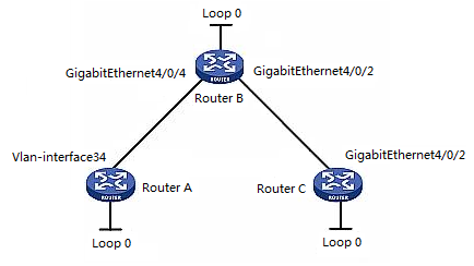
In this scenario, the main factor that causes network congestions is the network load imbalance. To ensure that important services can be smoothly transmitted along Router A —> Router B —> Router C, you should import Router A, Router B and Router C into MPLS TE Management, configure an MPLS TE tunnel using static CR-LSP, and then introduce traffic to it. Router A works as the ingress device, Router B works as the transit device and Router C works as the egress device.
· Router A—Device name is H3C-1; Device IP is 172.10.0.70; LSR ID address is 3.3.3.70; address of VLAN-interface 34 is 2.2.4.167.
· Router B—Device name is H3C; Device IP is 172.10.0.82; LSR ID address is 3.3.3.82; address of GigabitEthernet 4/0/4 is 2.2.4.4; address of GigabitEthernet 4/0/2 is 11.11.13.165.
· Router C—Device name is H3C-3; Device IP is 172.10.0.88; LSR ID is 3.3.3.88; address of GigabitEthernet 4/0/2 is 11.11.13.166.
Procedure
Import Router A, Router B and Router C into MPLS TE Management.
To configure an MPLS TE tunnel using static CR-LSP:
1. Click Service > MPLS TE Manager > MPLS TE Tunnel Mng at the top of the IMC main page.
2. In the MPLS TE Tunnel Query List section, click Add.
The Configure Static CR-LSP page opens, as shown in Figure 60.
Figure 60 Scenario 1—Add Tunnel page
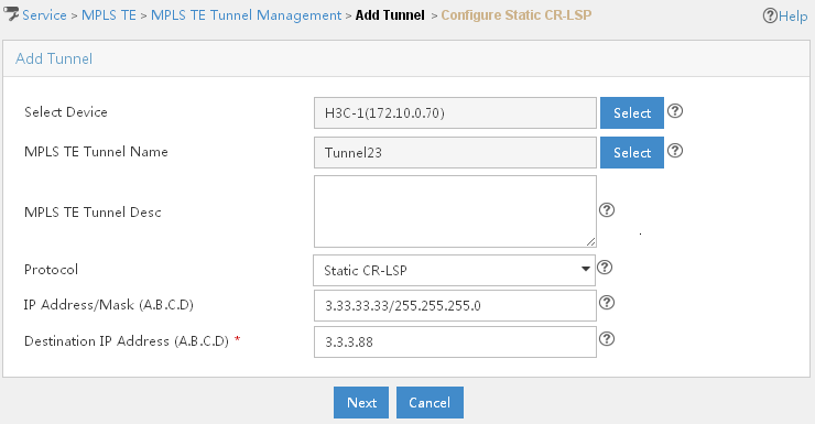
3. Specify the configuration information for the static CR-LSP.
a. Select Router A as the ingress device for the MPLS TE tunnel. Click Select next to Select Device. On the Select Device page, specify part or the entire name of Router A, and then click Query. Devices that match the description appear in the Device Query List section of the page. Select Router A, and then click OK.
b. On the Configure Static CR-LSP page, click Select next to MPLS TE Tunnel Name. Assign a name to the tunnel, and then click OK.
c. Enter the description for the tunnel, if needed.
d. Select Static CR-LSP from the Protocol list.
e. Assign an IP Address/Mask for the tunnel.
f. Enter the loopback address of Router C in the field of Destination IP Address (A.B.C.D), and then click Next.
4. In the Configure Static CR-LSP page, click Add. The Add Static CR-LSP Node screen with Ingress selected as the role is displayed, as shown in Figure 61.
Figure 61 Scenario 1—Add Static CR-LSP Node screen with Ingress selected as the role
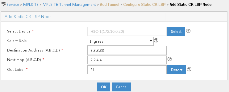
5. Add Router A as an ingress device node.
a. Click Select next to Select Device. In the Select Device page, specify part or the entire name of Router A, and then click Query. Devices that match the description appear in the Device Query List section of the page. Select Router A, and then click OK.
b. Select Ingress from the Select Role list.
c. In the Destination Address (A.B.C.D) field, enter the loopback address of Router C.
d. In the Next Hop (A.B.C.D) field, enter the in interface of Router B.
e. Next to Out Label, enter the out label value and click Detect to see if this value is available.
f. Click OK. The information of Router A is displayed in the Configure Static CR-LSP section of the page.
6. Add Router B as a transit device node.
a. In the Configure Static CR-LSP section of the page, click Add.
The Add Static CR-LSP Node screen with Transit selected as the role is displayed, as shown in Figure 62.
Figure 62 Scenario 1—Add Static CR-LSP Node screen with Transit selected as the role
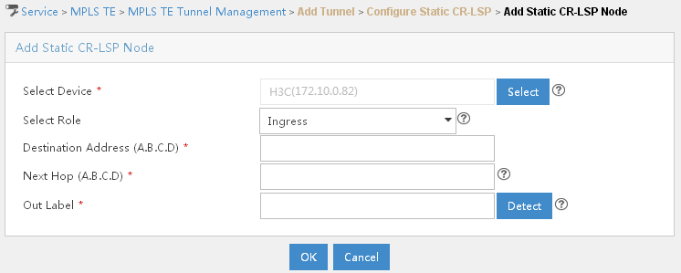
b. Click Select next to Select Device. In the Select Device page, specify part or the entire name of Router B, and then click Query. Devices that match the description appear in the Device Query List section of the page. Select the transit device, and then click OK.
c. Select Transit from the Select Role list. The In Interface field is populated with interfaces of Router B. Select the interface that you want to connect to Router A.
d. In the In Label field, enter the in label value and click Detect to see if this value is available.
e. In the Next Hop (A.B.C.D) field, enter the in interface of Router C.
f. In the Out Label field, enter the out label value of Router B. Click Detect to see if this value is available if needed.
g. Click OK. The information of the transit device is displayed in the Configure Static CR-LSP section of the page.
7. Add Router C as the egress device node.
a. In the Configure Static CR-LSP section of the page, click Add.
The Add Static CR-LSP Node screen with Egress selected as the role is displayed, as shown in Figure 63.
Figure 63 Add Static CR-LSP Node screen with Egress selected as the role

b. Click Select next to Select Device. In the Select Device page, specify part or the entire name of Router C, and then click Query. Devices that match the description appear in the Device Query List section of the page. Select Router C, and then click OK.
c. Select Egress from the Select Role list. The In Interface field is populated with the information of interfaces of Router C. Select the interface that you want to connect with Router B.
d. In the In Label field, enter the in label value and select Detect to see if this value is available.
e. Click OK. The information of Router C is displayed in the Configure Static CR-LSP section of the page.
f. Click Finish.
To introduce traffic to the static CR-LSP tunnel:
1. Click Service > MPLS TE Manager > Traffic Access Mng at the top of the IMC main page.
2. In the Access Traffic List section of the page, click Add.
The Traffic Access Type Selection page opens, as shown in Figure 64.
Figure 64 Scenario 1—Traffic Access Type selection page
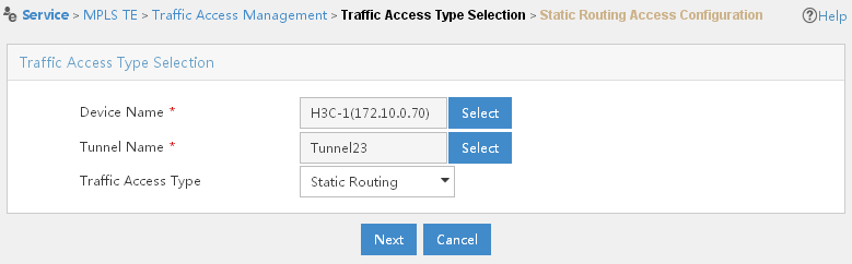
3. Click Select next to Device Name, enter part or the entire name of the Router A and click the Query button. Devices matching this description appear in the Device Query List section of the page. Select Router A, and then click OK.
4. Click Select next to Tunnel Name, enter part or the entire name of the tunnel that you have just created in the Tunnel Name field, and then click Query. Tunnels matching this description appear in the Tunnel Info List section of the page. Select your tunnel, and then click OK.
5. Select Static Routing from the Traffic Access Type list. In this usage scenario, the tunnel is a static CR-LSP route, so you should select the Static Routing option.
6. You are directed to the Static Routing Access Configuration page, as shown in Figure 65.
Figure 65 Scenario 1—Static Routing Access Configuration page
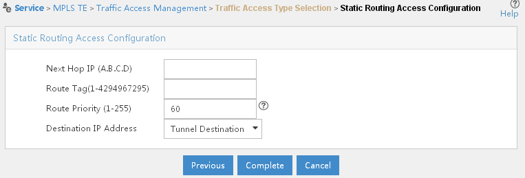
7. Click Complete. The traffic access is added successfully and is displayed in the Access Traffic List section of the page.
Scenario 2
A bank has four branches, branch A through branch D, which are connected to one another through networks. Branch A must send important data to branch D. It is required that there is enough bandwidth to guarantee the data transmission even if network congestion occurs.
Assume that the routers are reachable to each other after being configured with IS-IS or OSPF and are properly configured with basic MPLS and MPLS TE capabilities, as shown in Figure 66:
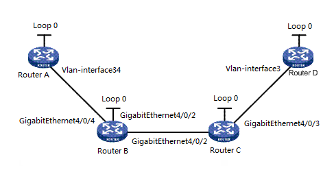
In this scenario, you must configure a dynamic MPLS TE tunnel from Router A to Router D through a dynamic signaling protocol RSVP-TE and reserve resources on the devices along the tunnel, so that data from Router A to Router D is always serviced.
· Router A—Device name is H3C-1; Device IP is 172.10.0.70; LSR ID address is 3.3.3.70; address of VLAN–interface 34 is 2.2.4.167.
· Router B—Device name is H3C; Device IP is 172.10.0.82; LSR ID address is 3.3.3.82; address of GigabitEthernet 4/0/4 is 2.2.4.4; address of GigabitEthernet 4/0/2 is 11.11.13.165.
· Router C—Device name is H3C-3; Device IP is 172.10.0.88; LSR ID address is 3.3.3.88; address of GigabitEthernet 4/0/2 is 11.11.13.166; address of GigabitEthernet 4/0/3 is 11.11.12.166.
· Router D—Device name is H3C-2; Device IP is 172.10.0.91; LSR ID address is 3.3.3.91; address of VLAN–interface 3 is 1.1.1.164.
Procedure
Import Router A, Router B, Router C, and Router D into MPLS TE Management.
To create a tunnel using the dynamic signaling protocol RSVP-TE:
1. Click Service > MPLS TE Manager > MPLS TE Tunnel Mng at the top of the IMC main page.
2. In the MPLS TE Tunnel Query List section of the page, click Add.
The Add Tunnel page opens, as shown in Figure 67.
Figure 67 Scenario 2—Add Tunnel page

3. Specify the configuration information for the dynamic MPLS TE tunnel.
a. Click Select next to Select Device, enter part or the entire name of Router A, and then click Query. All devices that match the description appear in the Device Query List section of the page. Select Router A, and then click OK.
b. Click Select next to MPLS TE Tunnel Name, assign a name to the tunnel, and then click OK.
c. Select RSVP-TE from the Protocol list.
d. Assign the IP address/mask to the tunnel, if needed.
e. In the Destination IP Address (A.B.C.D) field, enter the loopback address of Router D, and then click Next. You are directed to the Configure Basic Attributes page, as shown in Figure 68. You can use default settings on this page.
Figure 68 Scenario 2—Configure Basic Attributes page
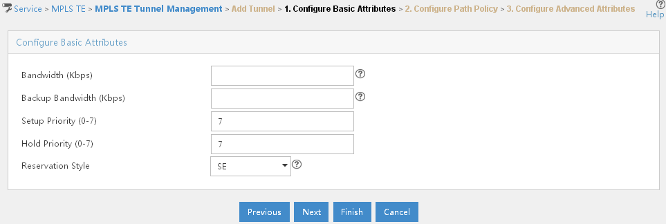
f. Click Next. The Configure Path Policy page opens, as shown in Figure 69. You can use default settings on this page.
Figure 69 Scenario 2—Configure Path Policy page
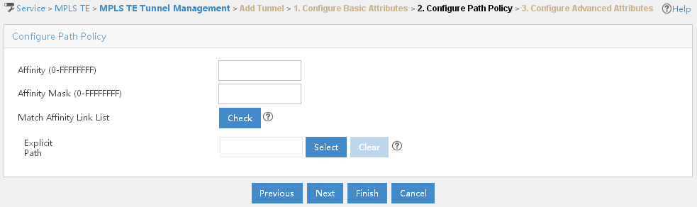
g. Click Next. You are directed to the Configure Advanced Attributes page.
h. Click OK. This tunnel is displayed in the MPLS TE Tunnel Query List section of the page.
To introduce traffic to this tunnel:
1. Click Service > MPLS TE Manager > Traffic Access Mng at the top of the IMC main page.
2. In the Access Traffic List section of the page, click Add. The Traffic Access Type Selection page is displayed, as shown in Figure 70.
Figure 70 Scenario 2—Traffic Access Type Selection page
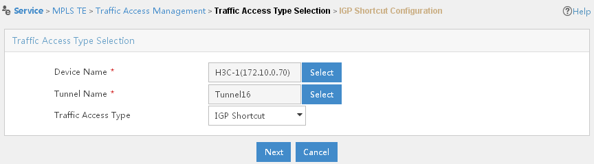
3. Click Select next to Device Name, enter part or the entire name of Router A and click the Query button. Devices matching this description appear in the Device Query List section of the page. Select Router A, and then click OK.
4. Click Select next to Tunnel Name, enter part or the entire name of the tunnel that you have just created in the Tunnel Name field, and then click Query. Tunnels matching this description appear in the Tunnel Info List section of the page. Select your tunnel, and then click OK.
5. Click Next.
6. Click Complete. The traffic access is added successfully and is displayed in the Access Traffic List section of the page.
Scenario 3
A company has four offices, office A through office D, which are connected with one another through networks. It is required to back up the forwarding of service data from office A to office C.
Assume that the routers are reachable to each other after being configured with IS-IS or OSPF and are properly configured with basic MPLS and MPLS TE capabilities, CR-LSP backup is configured at Router A, as shown in Figure 71:
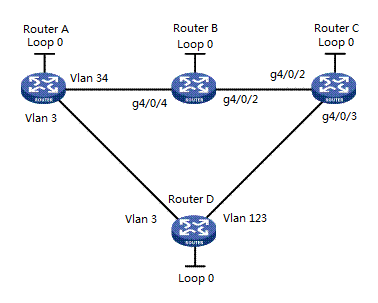
In this scenario, you can create two tunnels through a dynamic signaling protocol: tunnel A (Router A —> Router B —> Router C) and tunnel B Router A —> Router D —> Router C. Thus you can configure tunnel B as the CR-LSP backup tunnel of tunnel A. Then you should then introduce traffic to tunnel A.
|
|
NOTE: You cannot configure CR-LSP backup for MPLS TE tunnels configured using the static CR-LSP protocol. |
· Router A—Device name is H3C-1; Device IP is 172.10.0.70; LSR ID address is 3.3.3.70; address of VLAN 34 (VLAN-interface 34) is 2.2.4.167; address of VLAN 3 (VLAN-interface 3) is 2.2.4.299.
· Router B—Device name is H3C; Device IP is 172.10.0.82; LSR ID address is 3.3.3.82; address of g4/0/4 (GigabitEthernet 4/0/4) is 2.2.4.4; address of g4/0/2 (GigabitEthernet 4/0/2) is 11.11.13.165.
· Router C—Device name is H3C-3; Device IP is 172.10.0.88; LSR ID address is 3.3.3.88; address of g4/0/2 (GigabitEthernet 4/0/2) is 11.11.13.166.
· Router D—Device name is H3C-2; Device IP is 172.10.0.91; LSR ID address is 3.3.3.91; address of VLAN 3 (VLAN-interface 3) is 1.1.1.164; address of VLAN 123 (VLAN-interface 123) is 11.11.12.164.
Procedure
Import Router A, Router B, Router C and Router D into MPLS TE Management.
To configure an explicit path for the primary tunnel:
1. Click Service > MPLS TE Manager > Explicit Path Mng at the top of the IMC main page.
2. In the Explicit Path List section of the page, click Add.
The Add Explicit Path page opens, as shown in Figure 72.
Figure 72 Scenario 3—Add Explicit Path page
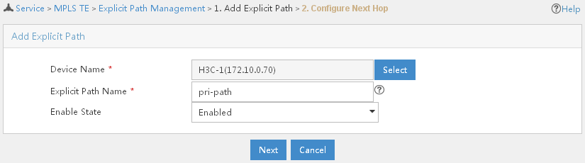
3. Click Select next to Device Name, specify part or the entire name of Router A, and then click Query. Devices that match the description appear in the Device Query List section of the page. Select Router A and click OK.
4. In the Explicit Path Name field, enter the name of the explicit path.
5. Select Enabled from the Enable State list.
6. Click Next.
7. On the Next Hop Info List page, click Add.
The Next Hop Info page opens, as shown in Figure 73.
Figure 73 Scenario 3—Next Hop Info page
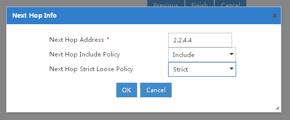
8. In the Next Hop Address field, enter the in interface address of your next hop (Router B).
9. Select Include from the Next Hop Include Policy list.
10. Select Strict from the Next Hop Strict Loose Policy list.
11. Click OK. Information about your next hop displays in the Next Hop Info List section of the page.
12. In the Next Hop Info List section of the page, click Add.
The Next Hop Info page opens, as shown in Figure 74.
Figure 74 Scenario 3—Next Hop Info page
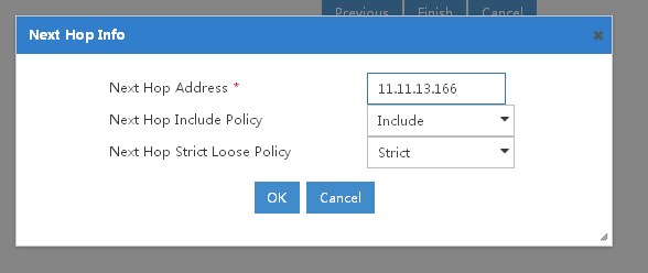
13. In the Next Hop Address field, enter the in interface address of your next hop (Router C).
14. Select Include from the Next Hop Include Policy list.
15. Select Strict from the Next Hop Strict Loose Policy list.
16. Click OK. Information about your next hop displays in the Next Hop Info List section of the page.
17. Click Finish. The explicit path is created and displayed in the Explicit Path List section of the Explicit Path Management page.
To create a tunnel from Router A to Router C using the dynamic signaling protocol RSVP-TE:
1. Click Service > MPLS TE Manager > MPLS TE Tunnel Mng at the top of the IMC main page.
2. In the MPLS TE Tunnel Query List section of the page, click Add.
The Add Tunnel page opens, as shown in Figure 75.
Figure 75 Scenario 3—Add Tunnel page

3. Specify the configuration information for the dynamic MPLS TE tunnel.
a. Click Select next to Select Device, enter part or the entire name of Router A and click Query. All devices that match the description appear in the Device Query List section of the page. Select Router A, and then click OK.
b. Click Select next to MPLS TE Tunnel Name, assign a name to the tunnel, and then click OK.
c. Select RSVP-TE from the Protocol list.
d. Assign the IP address/mask to the tunnel, if needed.
e. In the Destination IP Address (A.B.C.D) field, enter the loopback address of Router D, and then click Next. You are directed to the Configure Basic Attributes page, as shown in Figure 76.
Figure 76 Scenario 3—Configure Basic Attributes page
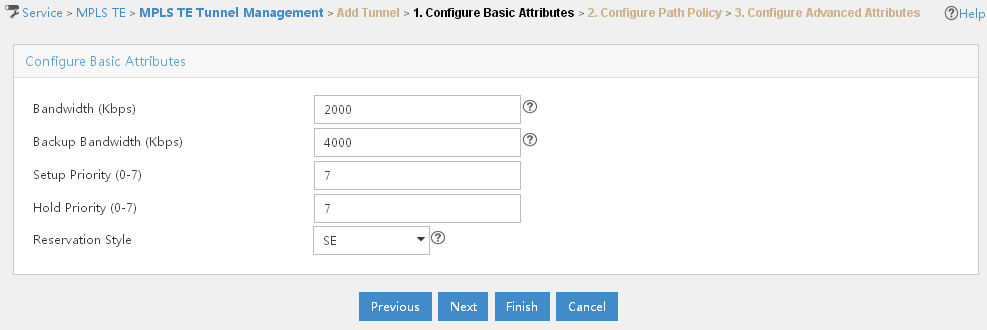
f. Enter information in the Bandwidth (Kbps) field and the Backup Bandwidth (Kbps) field. You need to configure the same settings accordingly on your devices.
g. Click Next. You are directed to the Configure Path Policy page, as shown in Figure 77.
Figure 77 Scenario 3—Configure Path Policy page

h. Refer to the explicit path that you have configured, and then click Next. You are directed to the Configure Advanced Attributes page.
i. Click OK. This tunnel is displayed in the MPLS TE Tunnel Query List section of the page.
Configure tunnel B in the similar way from Router A —> Router D —> Router C.
To introduce traffic to this tunnel:
1. Click Service > MPLS TE Manager > Traffic Access Mng at the top of the IMC main page.
2. In the Access Traffic List section of the page, click Add.
The Traffic Access Type Selection page opens, as shown in Figure 78.
Figure 78 Scenario 3—Traffic Access Type Selection page
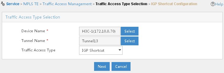
3. Click Select next to Device Name, enter part or the entire name of Router A and click the Query button. Devices matching this description appear in the Device Query List section of the page. Select Router A, and then click OK.
4. Click Select next to Tunnel Name, enter part or the entire name of the tunnel that you have just created in the Tunnel Name field, and then click Query. Tunnels matching this description appear in the Tunnel Info List section of the page. Select your tunnel, and then click OK.
5. Click Next.
6. Click Complete. The traffic access is added successfully and is displayed in the Access Traffic List section of the page.
1. Click Service > MPLS TE Manager > Protection Mng at the top of the IMC main page.
2. In the Tunnel Query section of the page, select MPLS TE Tunnel name, Tunnel State, or Protocol from the Query Type list, specify the corresponding value in the Value field, and then click Query. Tunnels matching this description appear in the Protected Tunnel List section of the page.
3. Find the tunnel that you want to configure
CR-LSP backup for, and then click the CR-LSP Backup
Operation icon![]() .
.
Scenario 4
A company has four offices, office A through office D, which are connected with one another through networks. It is required to protect the link between office B and office C, so that data packets can be switched to another path quickly when the link fails, and switched back to the original link after the original link resumes.
Assume that the routers are reachable to each other after being configured with IS-IS or OSPF and are properly configured with basic MPLS and MPLS TE capabilities, as shown in Figure 79:
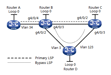
In this scenario, you must create the primary tunnel through a dynamic signaling protocol. The tunnel path is Router A —> Router B —> Router C. In this tunnel, the link between Router B and Router C is used to transmit important service data, and therefore, required to be protected. You must also create the bypass tunnel through a dynamic signaling protocol. The bypass tunnel path is Router B —> Router D —> Router C. After the link between Router B and Router C fails, the primary tunnel’s path will change to Router A —> Router B —> Router D —> Router C.
· Router A—Device name is H3C-1; Device IP is 172.10.0.70; LSR ID address is 3.3.3.70; address of VLAN 34 (VLAN-interface 34) is 2.2.4.167.
· Router B—Device name is H3C; Device IP is 172.10.0.82; LSR ID address is 3.3.3.82; address of g4/0/4 (GigabitEthernet 4/0/4) is 2.2.4.4; address of g4/0/2 (GigabitEthernet 4/0/2) is 11.11.13.165; address of g4/0/3 (GigabitEthernet 4/0/3) is 1.1.1.165.
· Router C—Device name is H3C-3; Device IP is 172.10.0.88; LSR ID address is 3.3.3.88; address of g4/0/2 (GigabitEthernet 4/0/2) is 11.11.13.166; address of g4/0/3 (GigabitEthernet 4/0/3) is 11.11.12.166.
· Router D—Device name is H3C-2; Device IP is 172.10.0.91; LSR ID address is 3.3.3.91; address of VLAN 3 (VLAN-interface 3) is 1.1.1.164; address of VLAN 123 (VLAN-interface 123) is 11.11.12.164.
Procedure
Import Router A, Router B, Router C, Router D into MPLS TE Management.
To configure an explicit path for the primary tunnel:
1. Click Service > MPLS TE Manager > Explicit Path Mng at the top of the IMC main page.
2. In the Explicit Path List section of the page, click Add.
The Add Explicit Path page opens, as shown in Figure 80.
Figure 80 Scenario 4—Add Explicit Path page
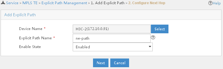
3. Click Select next to Device Name, specify part or the entire name of Router A, and then click Query. Devices that match the description appear in the Device Query List section of the page. Select Router A and click OK.
4. In the Explicit Path Name field, enter the name of the explicit path.
5. Select Enabled from the Enable State list.
6. Click Next.
7. On the Next Hop Info List page, click Add.
The Next Hop Info page opens, as shown in Figure 81.
Figure 81 Scenario 4—Next Hop Info page
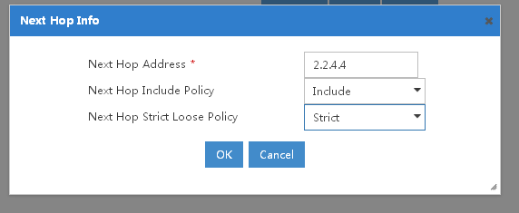
8. In the Next Hop Address field, enter the in interface address of your next hop (Router B).
9. Select Include from the Next Hop Include Policy list.
10. Select Strict from the Next Hop Strict Loose Policy list.
11. Click OK. Information about your next hop displays in the Next Hop Info List section of the page.
12. In the Next Hop Info List section of the page, click Add.
The Next Hop Info page opens, as shown in Figure 82.
Figure 82 Scenario 4—Next Hop Info page
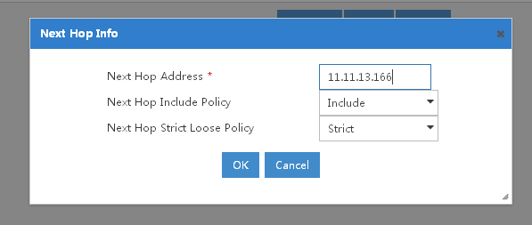
13. In the Next Hop Address field, enter the in interface address of your next hop (Router C).
14. Select Include from the Next Hop Include Policy list.
15. Select Strict from the Next Hop Strict Loose Policy list.
16. Click OK. Information about your next hop displays in the Next Hop Info List section of the page.
17. Click Finish. The explicit path is created and displayed in the Explicit Path List section of the Explicit Path Management page.
To create the primary tunnel using dynamic signaling protocol:
1. Click Service > MPLS TE Manager > MPLS TE Tunnel Mng at the top of the IMC main page.
2. In the MPLS TE Tunnel Query List section of the page, click Add.
The Add Tunnel page opens, as shown in Figure 83.
Figure 83 Scenario 4—Add Tunnel page

3. Specify the configuration information for the dynamic MPLS TE tunnel.
a. Click Select next to Select Device, enter part or the entire name of Router A and click Query. All devices that match the description appear in the Device Query List section of the page. Select Router A, and then click OK.
b. Click Select next to MPLS TE Tunnel Name, assign a name to the tunnel, and then click OK.
c. Select RSVP-TE from the Protocol list.
d. Assign the IP address/mask to the tunnel, if needed.
e. In the Destination IP Address (A.B.C.D) field, enter the loopback address of Router C, and then click Next. You are directed to the Configure Basic Attributes page, as shown in Figure 84.
Figure 84 Scenario 4—Configure Basic Attributes page
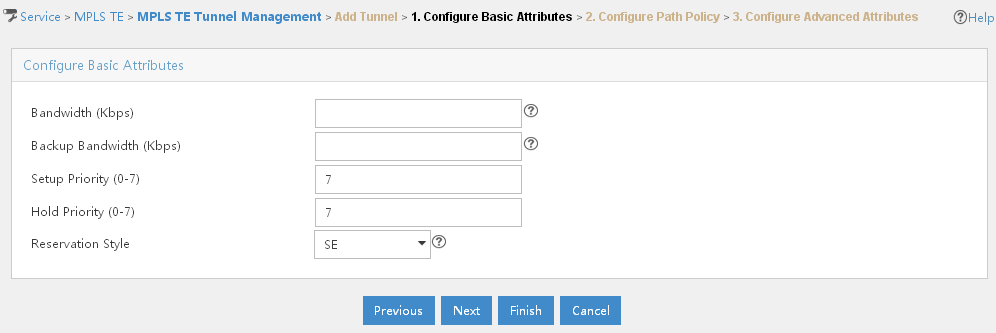
f. Click Next. You are directed to the Configure Path Policy page, as shown in Figure 85.
Figure 85 Scenario 4—Configure Path Policy page

g. Click Select next to Explicit Path, select the explicit path that you have just created, then click OK.
h. Click Next. You are directed to the Configure Advanced Attributes page.
i. Click OK. This tunnel is displayed in the MPLS TE Tunnel Query List section of the page.
To configure an explicit path for the bypass tunnel:
1. Click Service > MPLS TE Manager > Explicit Path Mng at the top of the IMC main page.
2. In the Explicit Path List section of the page, click Add.
The Add Explicit Path page opens, as shown in Figure 86.
Figure 86 Scenario 4—Add Explicit Path page
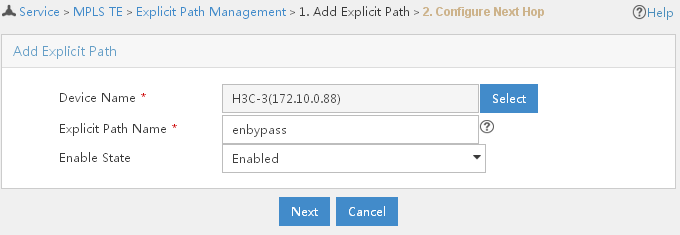
3. Click Select next to Device Name, specify part or the entire name of Router B, and then click Query. Devices that match the description appear in the Device Query List section of the page. Select Router B and click OK.
4. In the Explicit Path Name field, enter the name of the explicit path.
5. Select Enabled from the Enable State list.
6. Click Next.
7. On the Next Hop Info List page, click Add.
The Next Hop Info page opens, as shown in Figure 87.
Figure 87 Scenario 4 — Next Hop Info page
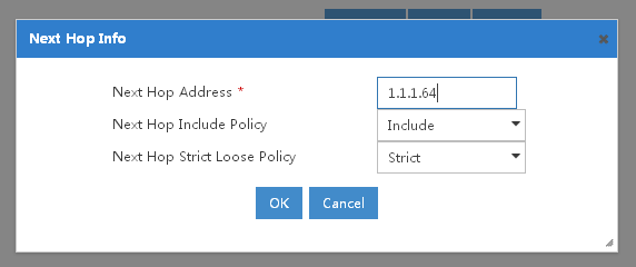
8. In the Next Hop Address field, enter the in interface address of your next hop (Router D).
9. Select Include from the Next Hop Include Policy list.
10. Select Strict from the Next Hop Strict Loose Policy list.
11. Click OK. Information about your next hop displays in the Next Hop Info List section of the page.
12. In the Next Hop Info List section of the page, click Add.
The Next Hop Info page opens, as shown in Figure 88.
Figure 88 Scenario 4—Next Hop Info page
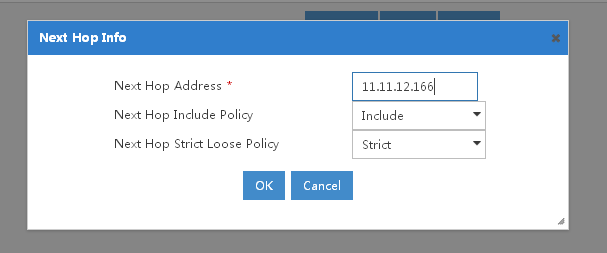
13. In the Next Hop Address field, enter the in interface address of your next hop (Router C).
14. Select Include from the Next Hop Include Policy list.
15. Select Strict from the Next Hop Strict Loose Policy list.
16. Click OK. Information about your next hop displays in the Next Hop Info List section of the page.
17. Click Finish. The explicit path is created and displays in the Explicit Path List section of the Explicit Path Management page.
To create the backup tunnel using dynamic signaling protocol:
1. Click Service > MPLS TE Manager > MPLS TE Tunnel Mng at the top of the IMC main page.
2. In the MPLS TE Tunnel Query List section of the page, click Add.
The Add Tunnel page opens, as shown in Figure 89.
Figure 89 Scenario 4—Add Tunnel page
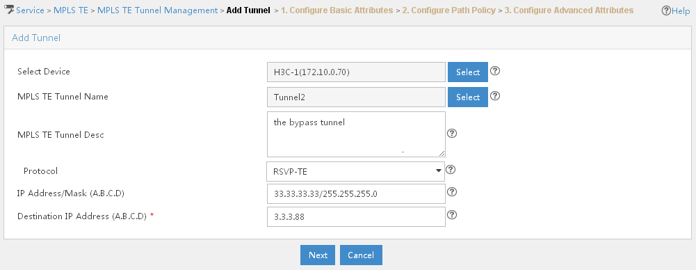
3. Specify the configuration information for the dynamic MPLS TE tunnel.
a. Click Select next to Select Device, enter part or the entire name of Router B and click Query. All devices that match the description appear in the Device Query List section of the page. Select Router B, and then click OK.
b. Click Select next to MPLS TE Tunnel Name, assign a name to the tunnel, and then click OK.
c. Select RSVP-TE from the Protocol list.
d. Assign the IP address/mask to the tunnel, if needed.
e. In the Destination IP Address (A.B.C.D) field, enter the loopback address of Router C, and then click Next. You are directed to the Configure Basic Attributes page, as shown in Figure 90.
Figure 90 Scenario 4—Configure Basic Attributes page

f. Click Next. You are directed to the Configure Path Policy page, as shown in Figure 91.
Figure 91 Scenario 4—Configure Path Policy page
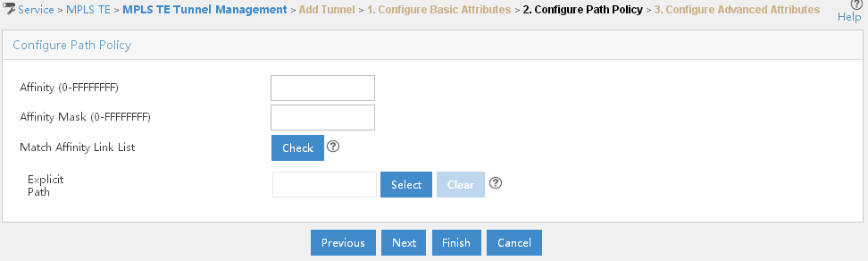
g. Click Select next to Explicit Path, select the explicit path that you have just created for the backup tunnel, then click OK.
h. Click Next. You are directed to the Configure Advanced Attributes page.
i. Click OK. The backup tunnel is displayed in the MPLS TE Tunnel Query List section of the page.
1. Click Service > MPLS TE Manager > Protection Mng at the top of the IMC main page.
2. In the Protected Tunnel List section of the page, select the bypass tunnel, and then click FRR Protection.
3. Select Link Protection from the Protection Type list.
4. Click Next.
5. In the Link List section of the page, select the link that you want to protect.
6. Click Next.
7. In the Protected Tunnel List section of the page, select the bypass tunnel, and then click Bound > Complete. The bypass tunnel is bound to the primary tunnel and is removed from the Protected Tunnel List section.
8. You can click the Operation
icon ![]() to view detailed information about the protection.
to view detailed information about the protection.
To introduce traffic to the primary tunnel:
1. Click Service > MPLS TE Manager > Traffic Access Mng at the top of the IMC main page.
2. In the Access Traffic List section of the page, click Add.
The Traffic Access Type Selection page opens, as shown in Figure 92.
Figure 92 Scenario 4—Traffic Access Type Selection page
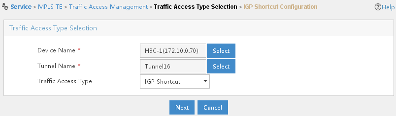
3. Click Select next to Device Name, enter part or the entire name of Router A and click the Query button. Devices matching this description appear in the Device Query List section of the page. Select Router A, and then click OK.
4. Click Select next to Tunnel Name, enter part or the entire name of the primary tunnel that you have just created in the Tunnel Name field, and then click Query. Tunnels matching this description appear in the Tunnel Info List section of the page. Select the primary tunnel, and then click OK.
5. Click Next.
6. Click Complete. The traffic access is added successfully and is displayed in the Access Traffic List section of the page.
Scenario 5
A company has five offices, office A through office E, which are connected with one another through networks. It is required to protect the link between office B and office D. After the link fails (for example, the device in office C fails), data packets can be forwarded quickly through another path, and, after the link resumes, data packets can be forwarded through the link again.
Assume that the routers are reachable to each other after being configured with IS-IS or OSPF and are properly configured with basic MPLS and MPLS TE capabilities, as shown in Figure 93:
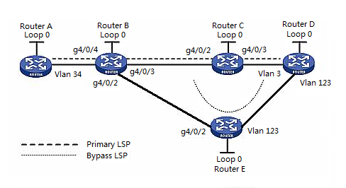
In this scenario, you must create the primary tunnel through a dynamic signaling protocol. The primary tunnel path is Router A —> Router B —> Router C —> Router D. In this tunnel, the link between Router B and Router D transmits important service data. Therefore it is required to protect the link's node Router C. You should also create the bypass tunnel by using a dynamic signaling protocol. The bypass tunnel path is Router B —> Router E —> Router D. After the link between Router B and Router D fails (for example, Router C cannot be pinged on the network), the path will change to Router A —> Router B —> Router E —> Router D.
· Router A—Device name is H3C-1; Device IP is 172.10.0.70; LSR ID address is 3.3.3.70; address of VLAN 34 (VLAN-interface 34) is 2.2.4.167.
· Router B—Device name is H3C; Device IP is 172.10.0.82; LSR ID address is 3.3.3.82; address of g4/0/4 (GigabitEthernet 4/0/4) is 2.2.4.4; address of g4/0/2 (GigabitEthernet 4/0/2) is 11.11.13.165; address of g4/0/3 (GigabitEthernet 4/0/3) is 1.1.1.165.
· Router C—Device name is H3C-3; Device IP is 172.10.0.88; LSR ID address is 3.3.3.88; address of g4/0/2 (GigabitEthernet 4/0/2) is 11.11.13.166; address of g4/0/3 (GigabitEthernet 4/0/3) is 11.11.12.166.
· Router D—Device name is H3C-2; Device IP is 172.10.0.91; LSR ID address is 3.3.3.91; address of VLAN 3 (VLAN-interface 3) is 1.1.1.164; address of VLAN 123 (VLAN-interface 123) is 11.11.12.164.
· Router E—Device name is H3C-4; Device IP is 172.10.0.92; LSR ID address is 3.3.3.92; address of VLAN 123 (VLAN-interface 123) is 11.11.12.133; address of g4/0/2 (GigabitEthernet 4/0/2) is 11.11.13.177.
Procedure
Import Router A, Router B, Router C, Router D and Router E into MPLS TE Management.
To configure an explicit path for the primary tunnel:
1. Click Service > MPLS TE Manager > Explicit Path Mng at the top of the IMC main page.
2. In the Explicit Path List section of the page, click Add.
The Add Explicit Path page opens, as shown in Figure 94.
Figure 94 Scenario 5—Add Explicit Path page
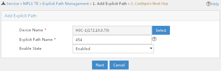
3. Click Select next to Device Name, specify part or the entire name of Router A, and then click Query. Devices that match the description appear in the Device Query List section of the page. Select Router A and click OK.
4. In the Explicit Path Name field, enter the name of the explicit path.
5. Select Enabled from the Enable State list.
6. Click Next.
7. On the Next Hop Info List page, click Add.
The Next Hop Info page opens, as shown in Figure 95.
Figure 95 Scenario 5—Next Hop Info page
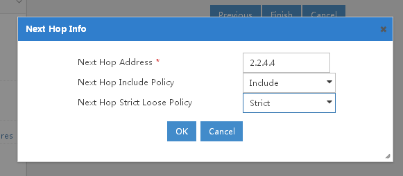
8. In the Next Hop Address field, enter the in interface address of Router B.
9. Select Include from the Next Hop Include Policy list.
10. Select Strict from the Next Hop Strict Loose Policy list.
11. Click OK. Information about your next hop displays in the Next Hop Info List section of the page.
12. In the Next Hop Info List section of the page, click Add.
The Next Hop Info is displayed, as shown in Figure 96.
Figure 96 Scenario 5—Next Hop Info page
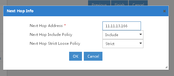
13. In the Next Hop Address field, enter the in interface address of Router C.
14. Select Include from the Next Hop Include Policy list.
15. Select Strict from the Next Hop Strict Loose Policy list.
16. Click OK. Information about your next hop displays in the Next Hop Info List section of the page.
17. In the Next Hop Info List section of the page, click Add.
The Next Hop Info page opens, as shown in Figure 97.
Figure 97 Scenario 5—Next Hop Info page
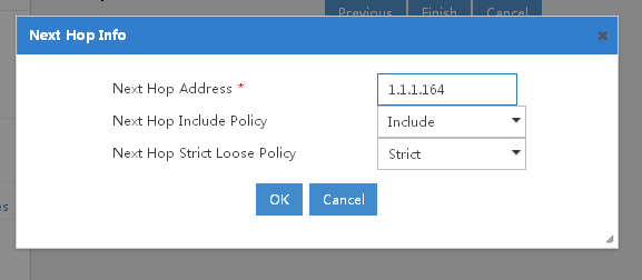
18. In the Next Hop Address field, enter the in interface address of Router D.
19. Select Include from the Next Hop Include Policy list.
20. Select Strict from the Next Hop Strict Loose Policy list.
21. Click OK. Information about your next hop displays in the Next Hop Info List section of the page.
22. Click Finish. The explicit path is created and displays in the Explicit Path List section of the Explicit Path Management page.
To create the primary tunnel using dynamic signaling protocol:
1. Click Service > MPLS TE Manager > MPLS TE Tunnel Mng at the top of the IMC main page.
2. In the MPLS TE Tunnel Query List section of the page, click Add.
The Add Tunnel page opens, as shown in Figure 98.
Figure 98 Scenario 5—Add Tunnel page
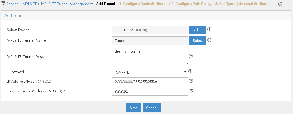
3. Specify the configuration information for the dynamic MPLS TE tunnel.
a. Click Select next to Select Device, enter part or the entire name of Router A and click Query. All devices that match the description appear in the Device Query List section of the page. Select Router A, and then click OK.
b. Click Select next to MPLS TE Tunnel Name, assign a name to the tunnel, and then click OK.
c. Select RSVP-TE from the Protocol list.
d. Assign the IP address/mask to the tunnel, if needed.
e. In the Destination IP Address (A.B.C.D) field, enter the loopback address of Router D, and then click Next. You are directed to the Configure Basic Attributes page, as shown in Figure 99.
Figure 99 Scenario 5—Configure Basic Attributes page
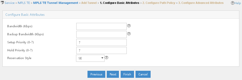
f. Click Next. You are directed to the Configure Path Policy page, as shown in Figure 100.
Figure 100 Scenario 5—Configure Path Policy page
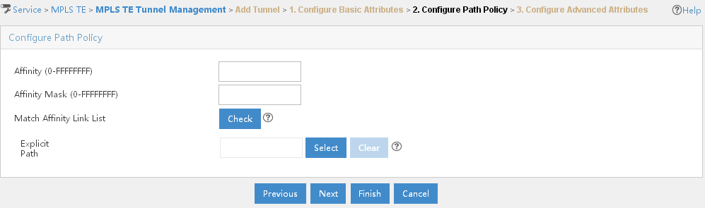
g. Click Select next to Explicit Path, select the explicit path that you have just created, then click OK.
h. Click Next. You are directed to the Configure Advanced Attributes page.
i. Click OK. This tunnel is displayed in the MPLS TE Tunnel Query List section of the page.
To configure an explicit path for the bypass tunnel:
1. Click Service > MPLS TE Manager > Explicit Path Mng at the top of the IMC main page.
2. In the Explicit Path List section of the page, click Add.
The Add Explicit Path page opens, as shown in Figure 101.
Figure 101 Scenario 5—Add Explicit Path page
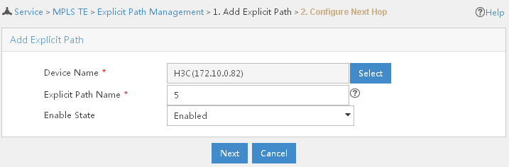
3. Click Select next to Device Name, specify part or the entire name of Router B, and then click Query. Devices that match the description appear in the Device Query List section of the page. Select Router B and click OK.
4. In the Explicit Path Name field, enter the name of the explicit path.
5. Select Enabled from the Enable State list.
6. Click Next.
7. On the Next Hop Info List page, click Add.
The Next Hop Info page opens, as shown in Figure 102.
Figure 102 Scenario 5—Next Hop Info page
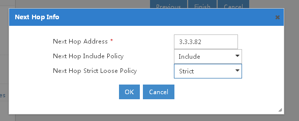
8. In the Next Hop Address field, enter the in interface address of Router E.
9. Select Include from the Next Hop Include Policy list.
10. Select Strict from the Next Hop Strict Loose Policy list.
11. Click OK. Information about your next hop displays in the Next Hop Info List section of the page.
12. In the Next Hop Info List section of the page, click Add.
The Next Hop Info page opens, as shown in Figure 103.
Figure 103 Scenario 5—Next Hop Info page
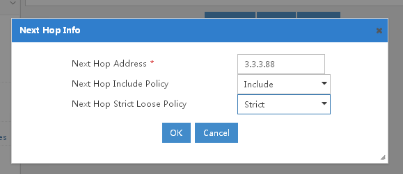
13. In the Next Hop Address field, enter the in interface address of Router D.
14. Select Include from the Next Hop Include Policy list.
15. Select Strict from the Next Hop Strict Loose Policy list.
16. Click OK. Information about your next hop displays in the Next Hop Info List section of the page.
17. Click Finish. The explicit path is created and displays in the Explicit Path List section of the Explicit Path Management page.
To create the backup tunnel using dynamic signaling protocol:
1. Click Service > MPLS TE Manager > MPLS TE Tunnel Mng at the top of the IMC main page.
2. In the MPLS TE Tunnel Query List section of the page, click Add.
The Add Tunnel page opens, as shown in Figure 104.
Figure 104 Scenario 5—Add Tunnel page
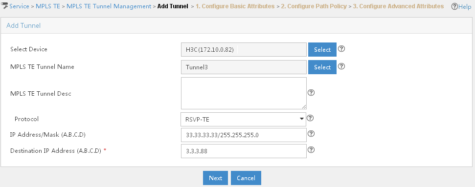
3. Specify the configuration information for the dynamic MPLS TE tunnel.
a. Click Select next to Select Device, enter part or the entire name of Router B and click Query. All devices that match the description appear in the Device Query List section of the page. Select Router B, and then click OK.
b. Click Select next to MPLS TE Tunnel Name, assign a name to the tunnel, and then click OK.
c. Select RSVP-TE from the Protocol list.
d. Assign the IP address/mask to the tunnel, if needed.
e. In the Destination IP Address (A.B.C.D) field, enter the loopback address of Router D, and then click Next. You are directed to the Configure Basic Attributes page, as shown in Figure 105.
Figure 105 Scenario 5—Configure Basic Attributes page

f. Click Next. You are directed to the Configure Path Policy page, as shown in Figure 106.
Figure 106 Scenario 5—Configure Path Policy page

g. Click Select next to Explicit Path, select the explicit path that you have just created for the backup tunnel, then click OK.
h. Click Next. You are directed to the Configure Advanced Attributes page.
i. Click OK. The backup tunnel is displayed in the MPLS TE Tunnel Query List section of the page.
1. Click Service > MPLS TE Manager > Protection Mng at the top of the IMC main page.
2. In the Protected Tunnel List section of the page, select the bypass tunnel, and then click FRR Protection.
3. Select Node Protection from the Protection Type list.
4. Click Next.
5. In the Node List section of the page, select the link that you want to protect.
6. Click Next.
7. In the Protected Tunnel List section of the page, select the bypass tunnel, and then click Bound > Complete. The bypass tunnel is bound to the primary tunnel and is removed from the Protected Tunnel List section.
8. You can click the Operation
icon ![]() to view detailed information about the protection.
to view detailed information about the protection.
To introduce traffic to the primary tunnel:
1. Click Service > MPLS TE Manager > Traffic Access Mng at the top of the IMC main page.
2. In the Access Traffic List section of the page, click Add.
The Traffic Access Type Selection page opens, as shown in Figure 107.
Figure 107 Scenario 5—Traffic Access Type Selection page
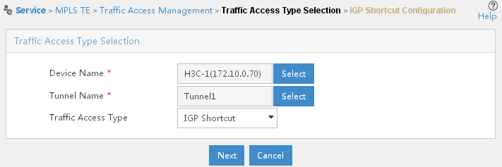
3. Click Select next to Device Name, enter part or the entire name of Router A and click the Query button. Devices matching this description appear in the Device Query List section of the page. Select Router A, and then click OK.
4. Click Select next to Tunnel Name, enter part or the entire name of the primary tunnel that you have just created in the Tunnel Name field, and then click Query. Tunnels matching this description appear in the Tunnel Info List section of the page. Select the primary tunnel, and then click OK.
5. Click Next.
6. Click Complete. The traffic access is added successfully and is displayed in the Access Traffic List section of the page.
Scenario 6
A company has four offices, office A through office D, which are connected with one another through networks. It is required that data from office A to office C must pass through the device (Router D) in office D. Assume that the routers are reachable to each other after being configured with IS-IS or OSPF and are properly configured with basic MPLS and MPLS TE capabilities, as shown in Figure 108.
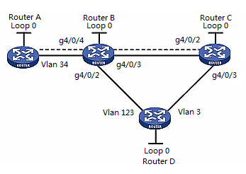
In this scenario, you want to force the tunnel to go through the specified node Router D. For the tunnel to pass through Router D, you must configure an explicit path that goes through Router D. In this way, the tunnel path is Router A —> Router B —> Router D —> Router C.
· Router A—Device name is H3C-1; Device IP is 172.10.0.70; LSR ID address is 3.3.3.70; address of VLAN 34 (VLAN-interface 34) is 2.2.4.167.
· Router B—Device name is H3C; Device IP is 172.10.0.82; LSR ID address is 3.3.3.82; address of g4/0/4 (GigabitEthernet 4/0/4) is 2.2.4.4; address of g4/0/2 (GigabitEthernet 4/0/2) is 11.11.13.163; address of g4/0/3 (GigabitEthernet 4/0/3) is 1.1.1.165.
· Router C—Device name is H3C-3; Device IP is 172.10.0.88; LSR ID address is 3.3.3.88; address of g4/0/2 (GigabitEthernet 4/0/2) is 11.11.13.166; address of g4/0/3 (GigabitEthernet 4/0/3) is 11.11.12.166.
· Router D—Device name is H3C-2; Device IP is 172.10.0.91; LSR ID address is 3.3.3.91; address of VLAN 3 (VLAN-interface 3) is 11.11.12.164; address of VLAN 123 (VLAN-interface 123) is 1.1.1.164.
Procedure
Import Router A, Router B, Router C, Router D into MPLS TE Management.
To create an explicit path that forces the tunnel to pass through router D:
1. Click Service > MPLS TE Manager > Explicit Path Mng at the top of the IMC main page.
2. In the Explicit Path List section of the page, click Add.
The Add Explicit Path page opens, as shown in Figure 109.
Figure 109 Scenario 6—Add Explicit Path page

3. Click Select next to Device Name, specify part or the entire name of Router B, and then click Query. Devices that match the description appear in the Device Query List section of the page. Select Router B and click OK.
4. In the Explicit Path Name field, enter the name of the explicit path.
5. Select Enabled from the Enable State list.
6. Click Next.
7. On the Next Hop Info List page, click Add.
The Next Hop Info page opens, as shown in Figure 110.
Figure 110 Scenario 6—Next Hop Info page
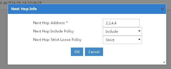
8. In the Next Hop Address field, enter the in interface address of Router B.
9. Select Include from the Next Hop Include Policy list.
10. Select Strict from the Next Hop Strict Loose Policy list.
11. Click OK. Information about your next hop displays in the Next Hop Info List section of the page.
12. In the Next Hop Info List section of the page, click Add.
The Next Hop Info page opens, as shown in Figure 111.
Figure 111 Scenario 6—Next Hop Info page
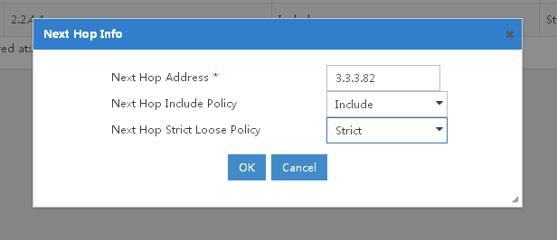
13. In the Next Hop Address field, enter the in interface address of Router D.
14. Select Include from the Next Hop Include Policy list.
15. Select Strict from the Next Hop Strict Loose Policy list.
16. Click OK. Information about your next hop displays in the Next Hop Info List section of the page.
17. In the Next Hop Info List section of the page, click Add.
The Next Hop Info page opens, as shown in Figure 112.
Figure 112 Scenario 6—Next Hop Info page
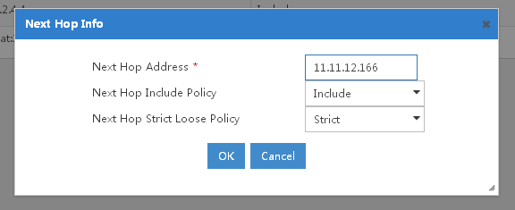
18. In the Next Hop Address field, enter the in interface address of Router C.
19. Select Include from the Next Hop Include Policy list.
20. Select Strict from the Next Hop Strict Loose Policy list.
21. Click OK. Information about your next hop displays in the Next Hop Info List section of the page.
22. Click Finish. The explicit path is created and displays in the Explicit Path List section of the Explicit Path Management page.
To create a tunnel using dynamic signaling protocol:
1. Click Service > MPLS TE Manager > MPLS TE Tunnel Mng at the top of the IMC main page.
2. In the MPLS TE Tunnel Query List section of the page, click Add.
The Add Tunnel page opens, as shown in Figure 113.
Figure 113 Scenario 6—Add Tunnel page
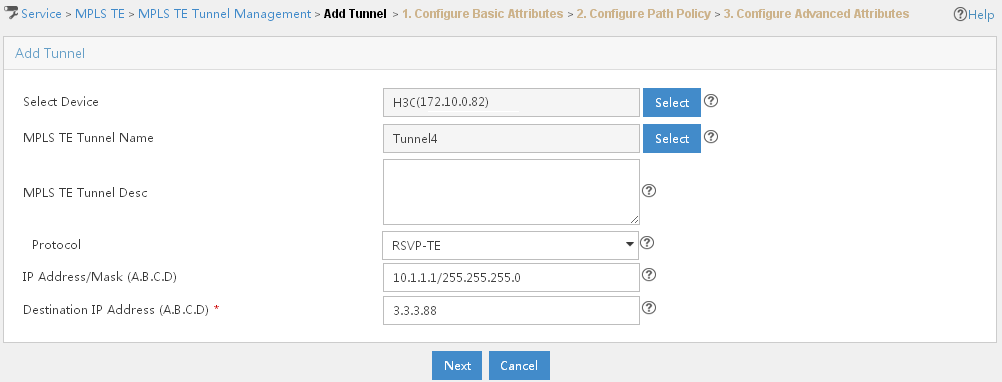
3. Specify the configuration information for the dynamic MPLS TE tunnel.
a. Click Select next to Select Device, enter part or the entire name of Router A and click Query. All devices that match the description appear in the Device Query List section of the page. Select Router A, and then click OK.
b. Click Select next to MPLS TE Tunnel Name, assign a name to the tunnel, and then click OK.
c. Select RSVP-TE from the Protocol list.
d. Assign the IP address/mask to the tunnel, if needed.
e. In the Destination IP Address (A.B.C.D) field, enter the loopback address of Router C, and then click Next. You are directed to the Configure Basic Attributes page, as shown in Figure 114.
Figure 114 Scenario 6—Configure Basic Attributes page

f. Click Next. You are directed to the Configure Path Policy page, as shown in Figure 115.
Figure 115 Scenario 6—Configure Path Policy page
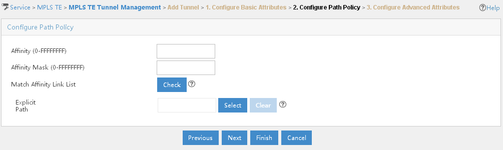
g. Click Select next to Explicit Path, select the explicit path that you have just created, then click OK.
h. Click Next. You are directed to the Configure Advanced Attributes page.
i. Click OK. This tunnel is displayed in the MPLS TE Tunnel Query List section of the page.
To introduce traffic to the tunnel:
1. Click Service > MPLS TE Manager > Traffic Access Mng at the top of the IMC main page.
2. In the Access Traffic List section of the page, click Add.
The Traffic Access Type Selection page opens, as shown in Figure 116.
Figure 116 Scenario 6—Traffic Access Type Selection page
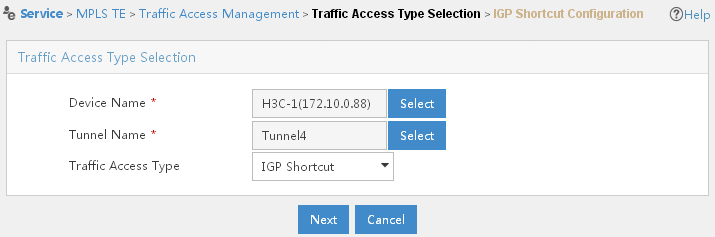
3. Click Select next to Device Name, enter part or the entire name of Router A and click the Query button. Devices matching this description appear in the Device Query List section of the page. Select Router A, and then click OK.
4. Click Select next to Tunnel Name, enter part or the entire name of the tunnel that you have just created in the Tunnel Name field, and then click Query. Tunnels matching this description appear in the Tunnel Info List section of the page. Select the tunnel that you have just created, and then click OK.
5. Click Next.
6. Click Complete. The traffic access is added successfully and is displayed in the Access Traffic List section of the page.
Using MPLS Management
MPLS management overview
MPLS management provides a comprehensive MPLS network management solution for metropolitan area networks. It cooperates with H3C devices to manage MPLS networks. MPLS management provides the following functions: Device Management, LDP Management, LSP Management, Topology Management, Label Statistics, and LSP Traffic Statistics.
MPLS management is based on the IMC platform. It adopts the B/S structure. Operators can manage and monitor MPLS networks anytime and anywhere from the local area network or Internet by using a browser without having to install any client.
Basic concepts
FEC
As a forwarding technology based on classification, MPLS groups packets with the same characteristics, such as packets with the same destination or service class, into a class, called a forwarding equivalence class (FEC). Packets of the same FEC are handled in the same way on an MPLS network. The device supports classifying FECs according to the network layer destination addresses of packets.
Label
A label is a short, fixed length identifier for identifying a single FEC. A label is locally significant and must be locally unique.
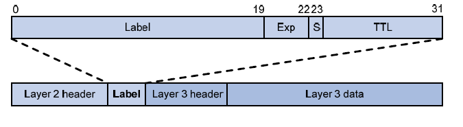
As shown in Figure 117, a label is encapsulated between the Layer 2 header and Layer 3 header of a packet. A label is four bytes in length and consists of the following fields:
· Label—20 bits in length. Label value for identifying a FEC.
· Exp—Three bits in length. Reserved field, usually used for CoS.
· S—One bit in length. MPLS supports multiple levels of labels. This field is used to indicate whether a label is at the bottom of the label stack. 1 indicates that the label is at the bottom of the label stack.
· TTL—Eight bits in length. Like the homonymous IP header field, it is used to prevent loops.
LSR
A label switching router (LSR) is a fundamental component on an MPLS network. LSRs support label distribution and label swapping.
LER
A label edge router (LER) is an LSR that resides at the edge of an MPLS network and is connected to another network.
LSP
A label switched path (LSP) is the path along which packets of a FEC travel through an MPLS network. An LSP is a unidirectional path from the ingress of an MPLS network to the egress. On an LSP, in the packet transfer direction, two neighboring LSRs are called the "upstream LSR" and "downstream LSR," respectively. As shown in Figure 118, LSR B is the downstream LSR of LSR A; LSR A is the upstream LSR of LSR B.
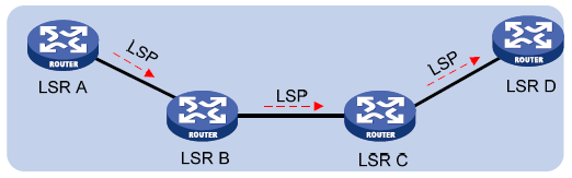
LFIB
On an MPLS network, labeled packets are forwarded according to the Label Forwarding Information Base (LFIB), which is like the FIB for IP packet forwarding on an IP network.
Control plane and forwarding plane
An MPLS node consists of two planes, control plane and forwarding plane.
· Control plane—Assigns labels, selects routes, establishes the LFIB, establishes and removes LSPs.
· Forwarding plane—Forwards packets according to the LFIB
As shown in Figure 119, the element of an MPLS network is LSR. LSRs in the same routing or administrative domain form an MPLS domain.
Figure 119 Diagram for the MPLS network structure
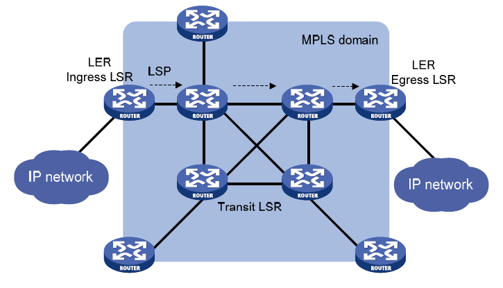
An MPLS domain consists of the following types of LSRs:
· Ingress LSRs for receiving and labeling packets coming into the MPLS domain.
· Transit LSRs for forwarding packets along LSPs to their egress LERs according to the labels.
· Egress LSRs for removing labels from packets and IP forwarding the packets to their destination networks.
In other words, transit LSRs perform MPLS forwarding based on labels of packets, and the ingress and egress LSRs deal with the switch-over between MPLS and IP forwarding.
Functions
To access main functions, click the Service tab at the top of the IMC main page, and then select MPLS Management > Quick Start from the left navigation tree. Main functions appear in the Quick Start page.
· Device Management—Allows operators to import devices from the IMC platform to the MPLS management component, to configure device LSR IDs, and to enable MPLS or MPLS LDP for devices and interfaces. Provides batch operations to facilitate device and interface management.
· LDP Management—Allows operators to manually create remote LDP peers and view session information between peers. In addition, the system can automatically discover local peers.
· LSP Management—Allows operators to manually add static LSPs on the topology, deploy, undeploy, delete, and audit LSPs. The system can also automatically add static LSPs and automatically discover LSPs.
· Topology Management—Displays the MPLS global network topology and LSPs between devices, and highlights LSPs.
· Label Statistics—Collects device label usage statistics and displays the top 5 devices with the highest dynamic or static label usage percentages in charts.
· LSP Traffic Statistics—Collects and displays LSP traffic statistics, allows operators to set LSP traffic thresholds, and generates outgoing traffic statistics reports from multiple perspectives.
Getting started with MPLS management
If you are using the MPLS management component for the first time:
1. Import devices.
Import the devices to be managed to the MPLS Management component, configure device LSR IDs, and enable MPLS and MPLS LDP for devices and interfaces. Only devices that have been added to IMC platform can be imported to MPLS Management component.
2. Create LDP peers.
Create remote LDP peers based on service requirement. Local LDP peers are automatically discovered, and session information between peers can be displayed. After LDP peers are successfully created, dynamic LSPs are generated. Remote peers mainly apply to Martini MPLS L2VPN, Martini VPLS, and MPLS LDP over MPLS TE.
3. Create LSPs.
The LSP management and topology functions allow you to manually create static LSPs. The system can also automatically create LSPs and discover LSP paths between devices. After LSPs are successfully created, you can deploy, undeploy, delete, and audit the LSPs.
4. View LSP traffic statistics.
Monitor LSPs, set LSP traffic alert thresholds, collect and view LSP traffic statistics, and view the outgoing traffic statistics report from different points of views.
· View device label statistics
View label usage statistics on devices and view the top 5 devices by label usage percentage in graphs and tables.
· Highlight an LSP on the topology
View the MPLS global network topology, view LSPs between devices, and highlight an LSP on the topology.
Using MPLS management component
Device management
This function enables you to manage devices in an MPLS network. You can import, synchronize, delete devices, and enable MPLS/MPLS LDP for devices and interfaces. Devices that can be managed by this system must meet the following conditions:
· Support MPLS.
· Can be accessed by Telnet or SSH.
· Have been added to IMC platform.
Importing devices
To import a device to the MPLS management:
1. Click Service > MPLS Management > Device Management at the top of the IMC main page.
2. Click the Import Devices button in the upper-left corner of the Device List.
3. Click the Select Devices button. In the pop-up page, select the devices by performing the following procedure:
a. Select devices from the Query Conditions pane with the following methods:
· Click the By View tab and select a network under the IP View to import devices in this network.
· Click the By View tab and select a device type under the Device View to import devices of a specific type, such as Routers, Switches, Servers, Desktops, and Others.
· Click the By View tab and select My Network View or Devices Not in Views.
· Click the Advanced tab and enter query conditions, as shown in Figure 120.
Figure 120 Select Devices page

¡ Device IP—Indicates the device IP address. This field supports fuzzy match. Select Exact Query to perform exact query.
¡ Device IP List—Click
the IP List icon ![]() to display the Device
IP List Configuration page. In this page, enter
one or more device IP addresses in the Input Device IP text box, and then
click the Add button. Click OK to confirm and go back to the previous page.
to display the Device
IP List Configuration page. In this page, enter
one or more device IP addresses in the Input Device IP text box, and then
click the Add button. Click OK to confirm and go back to the previous page.
¡ Device Label—Indicates the device name or label.
¡ Device Status—Indicates the device status. Values include Unmanaged, Unknown, Normal, Warning, Minor, Major, and Critical. Device Status is determined by the highest severity or alarm level for the device, when a device has more than one current alarm that has not been cleared or recovered. Devices that are added to but not managed by IMC are categorized as unmanaged. Devices whose information cannot be obtained by IMC are categorized as unknown.
¡ Device Category—Indicates the device type. Options include Routers, Switches, Servers, Security, Storage, Wireless, Voice, Surveillance, Video, Virtual Devices, Module, Application Controller, Printers, UPS, Desktops, and Others.
¡ Device Series—Indicates devices series.
¡ Contact—Indicates the contact information, such as user names or mobile phone numbers, of the operators who are responsible for the selected devices.
¡ Location—Indicates where the devices are located.
¡ Device Reachability—Indicates whether a device can be reached. Options include Reachable and Unreachable.
¡ Query—Click the Query button to display devices meeting the searching conditions in the Device Found pane.
a. To add one device to the import list,
highlight a single device entry in the Device Found pane, and then click the
Add selected icon ![]() . To add all devices to
the import list, click the Add all icon
. To add all devices to
the import list, click the Add all icon ![]() . Selected devices
appear in the Selected Devices pane.
. Selected devices
appear in the Selected Devices pane.
b. Click OK at the bottom of the page.
4. Click OK to start importing devices. During the importing process, the system displays the importing result showing when and whether a device has been successfully imported. You can stop the importing by clicking the Quit Device Importing link in the Operation box.
5. Click the Back button to go back to the Device List view and examine the imported devices.
|
|
NOTE: Only devices that have been added to the IMC platform can be imported to the MPLS management. |
Deleting devices
To delete one or more devices from the MPLS management:
1. Click Service > MPLS Management > Device Management at the top of the IMC main page.
2. Select one or more devices to be deleted.
3. Click the Delete Devices button in the upper-left corner of the Device List.
Querying devices
To query a device from the MPLS management:
1. Click Service > MPLS Management > Device Management at the top of the IMC main page.
2. Enter searching conditions in the Query Devices pane:
· Device Name—Indicates the device names or IP addresses.
· Device Status—Indicates the device status. Values include All, Unmanaged, Unknown, Normal, Warning, Minor, Major, and Critical. Device Status is determined by the highest severity or alarm level for the device when a device has more than one current alarm that has not been cleared or recovered. Devices that are added to but not managed by IMC are categorized as unmanaged. Devices whose information cannot be obtained by IMC are categorized as unknown.
· MPLS LDP Status—Indicates the MPLS LDP status. Values include: All, Enabled and Disabled.
· LSR ID—Indicates the LSR ID.
· MPLS Status—Indicates the MPLS status. Values include: All, Enabled and Disabled.
3. Click the Query Devices button. The Device List displays all the devices that match the searching conditions. Click the Reset button to clear the searching conditions.
|
|
NOTE: The Device Name and LSR ID fields support fuzzy match. |
Synchronizing devices
The synchronization function enables the system to obtain configuration information from the specified devices immediately, and to manage the device information in MPLS management. You can determine whether the current device configuration is valid by checking the last synchronization time and synchronization status of the device.
To synchronize one or more devices from the MPLS management:
1. Click Service > MPLS Management > Device Management at the top of the IMC main page.
2. Select one or more devices to be synchronized.
3. Click the Synchronize button in the upper-left corner of the Device List.
|
|
NOTE: · The synchronization process may take a while. You may need to click the Refresh button to display the latest synchronization status. · Do not synchronize devices when adding LSPs. Synchronize devices before you add LSPs to avoid possible errors. |
Enabling MPLS and MPLS LDP for devices
This function enables you to configure the LSR ID for a device, and to decide whether to enable MPLS and MPLS LDP for the device. In an MPLS domain, you must enable MPLS on all devices for MPLS forwarding before you can configure other MPLS features.
To enable MPLS and MPLS LDP for a device:
1. Click Service > MPLS Management > Device Management at the top of the IMC main page.
2. Click the Operation
icon ![]() for a device entry. The operation menu opens
and lists all the operations that you can perform.
for a device entry. The operation menu opens
and lists all the operations that you can perform.
3. Select Enable MPLS/LDP from the menu. The Configure MPLS/MPLS LDP for Device page opens.
4. Select Enabled for MPLS Status and MPLS LDP Status, respectively.
5. Click OK.
|
|
NOTE: · If a device has been already configured with an LSR ID before or after it is added to the MPLS management, you cannot change the LSR ID for the device in MPLS management. To re-configure a device LSR ID, an administrator must log into the device and execute related commands. · If no LSR ID is configured for a device, you can use the IP address of the loopback interface on the device as the device LSR ID. · You cannot enable MPLS and MPLS LDP for a device when the device LSR ID is not configured. · You cannot enable MPLS LDP for a device when the MPLS Status of the device is set to Disabled. |
Batch enabling MPLS and MPLS LDP for devices
Use this function to enable MPLS and MPLS LDP for multiple devices in bulk. Before you use this function, make sure the device LSR IDs have been configured.
To batch enable MPLS and MPLS LDP for devices:
1. Click Service > MPLS Management > Device Management at the top of the IMC main page.
2. Select the target devices from the Device List, and then click Enable MPLS/LDP in the upper-left corner.
3. Select Enabled for MPLS Status and MPLS LDP Status, respectively.
4. Click OK.
|
|
NOTE: · You cannot enable MPLS/LDP for a device when the device LSR ID is not configured. · To enable MPLS LDP for a device, you must enable MPLS for the device first. |
Device advanced configuration
This function enables you to configure the GR for Session, Reconnect Timer (s), FT Reconnect Timer, and Neighbor Liveness Timer (s) for a device that has been imported to the MPLS management.
|
|
NOTE: The Advanced Configuration option is available in the operation menu only after the device MPLS and LDP are enabled. |
To display the device Advanced Configuration page:
1. Click Service > MPLS Management > Device Management at the top of the IMC main page.
2. Click the Operation
icon ![]() for a device entry. The operation menu opens
and lists all the operations that you can perform.
for a device entry. The operation menu opens
and lists all the operations that you can perform.
3. Select Advanced Configuration from the menu. The Advanced Configuration page opens.
4. Modify the related parameters:
· GR for Session—LDP Graceful Restart (GR) enables an LSR to keep MPLS forwarding entries during an LDP restart, ensuring continuous MPLS forwarding. It is disabled by default.
· Recovery Timer (s)—LDP recover timers. During the LDP recovery time, LSRs use the re-established LDP session to exchange label bindings, update label forwarding entries, and clear the stale tags for the entries. When the Recovery timer expires, the GR helper deletes the label forwarding entries still marked stale. The value range for the LDP Recovery Timer is 3 to 300 seconds.
· FT Reconnect Timer—When an LDP session is down, the GR helper marks the FEC-label mappings learned from the session as stale and keeps these FEC-label bindings for a period of time defined as the Fault Tolerant (FT) reconnect timer. If the LDP session is not set up before the reconnect timer expires, the GR helper deletes the stale FEC-label mappings and the corresponding MPLS forwarding entries. If the LDP session is successfully re-established, the GR helper starts the recovery timer. The value range for the FT Reconnect Timer is 60 to 300 seconds.
· Neighbor Liveness Timer (s)—The maximum time that a GR helper maintains the neighbor relationship with the GR restarter and helps the GR restarter restore its LFIB information when a session is down.
5. Click OK.
|
|
NOTE: You can configure the LDP Recovery Timer and FT Reconnect Timer for a device only when the GR for Session feature is enabled for the device. |
Device Traffic Configuration
This function enables you to enable or disable Traffic Statistics, and to set Traffic Statistics Interval(s).
To configure device traffic statistics:
1. Click Service > MPLS Management > Device Management at the top of the IMC main page.
2. Click the Operation
icon ![]() for a device entry. The operation menu opens
and lists all the operations that you can do.
for a device entry. The operation menu opens
and lists all the operations that you can do.
3. Click Traffic Configuration in the operation menu to display the Configure Device Traffic Statistics page of the device.
4. Select Enable or Disable.
5. Enter statistics interval in the Traffic Statistics Interval (s) text box.
6. Click OK.
Viewing device label statistics
This function enables you to view label usage statistics of a device, including the Number of Used Labels, Number of Unused Labels, and the Label Usage Percentage.
To view device label statistics:
1. Click Service > MPLS Management > Device Management at the top of the IMC main page.
2. Click the Operation
icon ![]() for a device entry. The operation menu opens
and lists all the operations that you can perform.
for a device entry. The operation menu opens
and lists all the operations that you can perform.
3. Click Label Statistics in the operation menu to display the Label Usage Statistics page of the device.
4. Click a link in the Number of Used Labels column to view detailed label usage information.
Three rows in the Label Type field are: Static, Dynamic, and Static and Dynamic. Static labels are assigned manually to establish a static LSP. Dynamic labels are assigned through label distribution protocols to establish a dynamic LSP. The value of Static and Dynamic is the sum of Static and Dynamic.
Querying device interface information
This function enables you to query interfaces of a specific device by Interface Description, Interface IP Address, MPLS Status, and MPLS LDP Status.
1. Click Service > MPLS Management > Device Management at the top of the IMC main page.
2. Click the Operation
icon ![]() for a device entry, and then select Configure MPLS/LDP for Interface from the operation menu.
The interface configuration page for the selected device opens.
for a device entry, and then select Configure MPLS/LDP for Interface from the operation menu.
The interface configuration page for the selected device opens.
3. Enter search conditions:
· Interface Description—Indicates the description of an interface.
· Interface IP—Indicates the interface IP address.
· MPLS LDP Status—Indicates the MPLS LDP status. Values include: All, Enabled and Disabled.
· MPLS Status—Indicates the MPLS status. Values include: All, Enabled and Disabled.
4. Click the Query button. The Interface Information List displays all the interfaces that match the search conditions. Click the Reset button to clear the search conditions.
|
|
NOTE: The Interface Description and Interface IP fields support fuzzy match. |
Enabling MPLS or MPLS LDP for interfaces
Use this function to enable MPLS and MPLS LDP for an interface of a device that has been imported to the MPLS management.
1. Click Service > MPLS Management > Device Management at the top of the IMC main page.
2. Click the Operation
icon ![]() for a device entry, and then select Configure
MPLS/LDP for Interface from the operation menu. The interface
configuration page for the selected device opens.
for a device entry, and then select Configure
MPLS/LDP for Interface from the operation menu. The interface
configuration page for the selected device opens.
3. Click the Configure
MPLS/LDP for Interface icon ![]() for an interface entry.
for an interface entry.
4. Select Enabled for MPLS Status and MPLS LDP Status, respectively.
5. Click OK.
|
|
NOTE: You cannot enable MPLS LDP for an interface when the MPLS status of the interface is Disabled. |
Batch enable MPLS or MPLS LDP for interfaces
Use this function to batch enable MPLS/MPLS LDP for multiple interfaces on a device. Before you use this function, make sure the device has been imported to the MPLS management.
1. Click Service > MPLS Management > Device Management at the top of the IMC main page.
2. Click the Operation
icon ![]() for a device entry, and then select Configure
MPLS/LDP for Interface from the operation menu. The interface
configuration page for the selected device opens.
for a device entry, and then select Configure
MPLS/LDP for Interface from the operation menu. The interface
configuration page for the selected device opens.
3. Select one or more target interfaces, and then click the Enable MPLS/LDP button in the upper-left corner of the Interface Information List.
4. Select Enabled for MPLS Status and MPLS LDP Status, respectively.
5. Click OK.
|
|
NOTE: You cannot enable MPLS LDP for an interface when the MPLS status of the interface is Disabled. You must enable the MPLS first. |
LDP Management
LDP management is used to manage LDP peers which include local peers and remote peers. By enabling MPLS LDP for devices, remote LDP peers must be created on devices manually, while local LDP peers can be created through automatic discovery. Local peers are discovered through the basic discovery mechanism defined in the LDP protocol. Remote peers are discovered through the extended discovery mechanism. Basic discovery mechanism discovers directly connected LSRs, and establishes link hello adjacencies with them. Extended discovery mechanism discovers indirectly connected LSRs and establishes targeted hello adjacencies. In LDP management, you can query, add, configure, delete LDP peers, and view LDP session information established between LDP peers.
Querying LDP peers
This function enables you to query LDP peers by Local Device, Peer Device, Session Status, Status (whether the peer relationship is normal), and Type (type of the LDP peers).
1. Click Service > MPLS Management > LDP Management at the top of the IMC main page.
2. Enter searching conditions in the Query LDP Peers pane:
· Local Device—Indicates the local device name or IP address.
· Peer Device—Indicates the peer device name or IP address.
· Session Status—Indicates the session status. Values include All, NonExistent, Initialized, Open-Received, Open-Sent, and Operational.
· Status—Indicates the peer status. Values include All, Normal, and Abnormal.
· Type—Indicates the peer types. Values include All, Local, and Remote.
3. Click the Query button. The Peer List displays all the peers that match the searching conditions. Click the Reset button to clear the searching conditions.
|
|
NOTE: The Local Device and Peer Device fields support fuzzy match. |
Adding LDP peers
This function enables you to create an LDP peer relationship between two devices so that the devices can generate label forwarding entries, and dynamically establish and maintain LSPs. After you create a peer relationship between two devices, the two devices are called a pair of LDP peers, which are uniquely identified by the peer relationship name.
1. Click Service > MPLS Management > LDP Management at the top of the IMC main page.
2. Click the Add button in the upper-left corner.
3. Enter the Local Device Name, the Peer Device Name, and the Peer Relationship Name.
4. Click OK.
|
|
NOTE: · When you enter the local device name or the peer device name (including the device IP addresses), the system automatically displays all devices with names containing the provided characters in the list. You can select the target device from the list. For example, if you enter Test, the system displays all devices with names containing Test in the list. · The peer relationship name can contain up to 32 characters and must be unique in the system. |
Deleting LDP peers
This function enable you to delete LDP peers from MPLS management. After you delete a peer relationship, the corresponding peers and the LDP session established between the peers are also deleted from the MPLS management component.
1. Click Service > MPLS Management > LDP Management at the top of the IMC main page.
2. Select one or more pairs of peers from the Peer List, and then click the Delete button in the upper-left corner.
3. Click OK in the pop-up confirmation page.
|
|
NOTE: · You can only delete remote LDP peers. Local LDP peers are generated through automatic negotiation and cannot be deleted. · After an LDP peer relationship between two devices is deleted, the LDP session established between the devices is also deleted, and the devices can no longer advertise labels and dynamically create LSPs. |
Configuring LDP peer parameters
This function enables you to configure specific parameters for existing LDP peers to facilitate dynamic establishment of LSPs.
To configure LDP peer parameters:
1. Click Service > MPLS Management > LDP Management at the top of the IMC main page.
2. Click the Operation
icon ![]() for a pair of LDP peers, and then select Advanced Configuration from the operation menu. The Advanced Configuration page for the selected peers opens.
for a pair of LDP peers, and then select Advanced Configuration from the operation menu. The Advanced Configuration page for the selected peers opens.
3. Modify parameters:
· Keepalive Timer (s)—Maximum time allowed to receive an LDP PDU (one LDP PDU can carry one or more LDP messages). When the timer expires, the LSR closes the TCP connection and terminates the LDP session. The Keepalive timer value ranges from 1 to 65535 seconds.
· Hello Timer (s)—Maximum time an LSR waits to receive a hello message. LDP peers periodically send Hello messages to indicate that they intend to keep the Hello adjacency. If an LSR does not receive an Hello message from a peer before the Hello timer expires, it deletes the Hello adjacency with this peer. When the last Hello adjacency for the session is deleted, the LSR sends a Notification message to terminate the LDP session. The Hello timer value ranges from 1 to 65535 seconds.
· MD5 Authentication—To improve the security of LDP sessions, you can configure MD5 authentication for the underlying TCP connections, so that the TCP connections can be established only if the peers have the same authentication password. Values include: Disable and Enable. If you select Enable, the password text box opens.
· Label Advertisement Mode—Only the Downstream Unsolicited (DU) mode is supported. In this mode, an LSR automatically assigns a label to an FEC and then distributes the FEC-label binding to its upstream LSR.
· Peer Path Vector Length—Maximum number of hops for an LSP contained in a label request message or label mapping message. An LSR terminates the establishment of an LSP when the hop count of the path, or the length of the path vector, reaches the upper limit.
|
|
NOTE: The Advanced Configuration option is available for a pair of peers only when the peer Status is Normal and the Session Status is Operational. Otherwise, you can only view the peer details. |
Viewing session information
LDP sessions are established between LSRs based on TCP connections and used to exchange messages for label binding, label releasing, and error notification. This viewing function enables you to view the session information and configuration of a pair of LDP peers.
1. Click Service > MPLS Management > LDP Management at the top of the IMC main page.
2. Click the Operation
icon ![]() for a pair of LDP peers, and then select Session Information from the operation menu.
for a pair of LDP peers, and then select Session Information from the operation menu.
3. You can view the following parameters in the Session Information page:
· Local LSR ID—Indicates local LSR ID.
· Peer LSR ID—Indicates peer LSR ID.
· TCP Connection—Indicates the TCP connection based on which the LDP session is created.
· Session Status—Indicates session status. Values include: All, NonExistent, Initialized, Open-Received, Open-Sent, and Operational.
· Local Device’s Role in Session—Indicates device role in session. Values include: Active and Passive.
· Keepalive Timer (s)—Maximum time allowed to receive an LDP PDU. One LDP PDU can carry one or more LDP messages. When the timer expires, the LSR closes the TCP connection and terminates the LDP session. The Keepalive timer value ranges from 1 to 65535 seconds.
· Hello Timer (s)—Maximum time an LSR waits to receive a hello message. LDP peers periodically send Hello messages to indicate that they intend to keep the Hello adjacency. If an LSR does not receive an Hello message from a peer before the Hello timer expires, it deletes the Hello adjacency with this peer. When the last Hello adjacency for the session is deleted, the LSR sends a Notification message to terminate the LDP session. The Hello timer value ranges from 1 to 65535 seconds.
· MD5 Authentication—Values include Disable and Enable.
· Label Advertisement Mode—Only the DU mode is supported. In this mode, an LSR automatically assigns a label to an FEC and then distributes the FEC-label binding to its upstream LSR.
· Label Resource Status (Peer/Local)—Indicates the label resource status.
· Peer Discovery Mechanism—Local peers are discovered through the Basic discovery mechanism. Remote peers are discovered through the Extended discovery mechanism.
· Session Up Time—Indicates the connection time of a session.
· Label Acceptance Policy—The policy for filtering received label bindings. An upstream LSR filters the label bindings received from the specified downstream LSR and accepts only those permitted by the specified prefix list.
|
|
NOTE: You can view the session information of a pair of peers only when the Session Status is Operational. |
Viewing LDP peer details
1. Click Service > MPLS Management > LDP Management at the top of the IMC main page.
2. Click the Operation
icon ![]() for a pair of LDP peers, and then select Details from the operation menu. The LDP Peer Details page for the selected peers opens.
for a pair of LDP peers, and then select Details from the operation menu. The LDP Peer Details page for the selected peers opens.
|
|
NOTE: You can view detailed information about a pair of LDP peers only when the status of the peer relationship is Abnormal or the session status of the peers is not Operational. |
LSP Management
With the LSP Management function, you can deploy MPLS LSPs in a simple and user-friendly way. You do not need to go to various device equipment rooms or execute raw command lines to set up or maintain LSPs. The network maintenance time and difficulties are highly reduced.
With basic network information well configured, you can deploy an entire LSP network or adjust some deployments of an LSP network. After an LSP is deployed, you can highlight an LSP for intuitive observation. You can also manually add static LSPs on the topology, automatically add static LSPs, automatically discover LSPs, and delete and audit LSPs.
Querying LSPs
Over time, the LSP list can grow large, making it more difficult for you to find an LSP at an glance. The Query capability enables you to query LSPs by LSP name, ingress device name, egress device name, audit status, deployment status, and LSP type.
1. Click Service > MPLS Management > LSP Management at the top of the IMC main page.
2. In the Query LSPs section of the page, specify the following query conditions:
· LSP Name—Indicates the LSP name.
· Ingress Device Name—Indicates the name of the ingress device.
· Egress Device Name—Indicates the name of the egress device.
· Audit Status—Indicates the audit status of the LSP. Values include All, Up, Down, Unknown, Auditing, Testing, Dormant, Not Present, and Lower Layer Down.
· Deployment Status—Indicates the deployment status of the LSP. Values include All, Normal, Undeployed, Deploying, Undeploying, Deployment failed, and Undeployment failed.
· LSP Type—Indicates the type of the LSP. Values include All, Static, Dynamic, and CR-LSP.
MPLS Management supports fuzzy query function, which allows you to specify intact or partial query condition.
3. Click the Query button. All LSPs that match the query criteria are displayed in the LSP List section of the page.
4. To clear the query criteria and display all LSPs, click the Reset button.
Adding a static LSP
You can establish an LSP between specified devices either manually or automatically. You can deploy the LSP immediately after the LSP is generated or deploy all LSPs in a batch.
Configuration procedure
1. Configure a path, either manually or automatically, for the static LSP.
2. Assign values to outgoing labels.
3. Check labels (optional).
4. Deploy the LSP.
Configuring a path for the static LSP manually
You can manually configure the path and basic information for the LSP.
To manually configure a path for the static LSP:
1. Click Service > MPLS Management > LSP management at the top of the IMC main page.
2. In the LSP List section of the page, click the Add Static LSP button.
3. Scroll down to the bottom of the page, and then click the Manual Deployment.
4. In the Topology section of the page, right-click the device on the topology that you want to specify as the LSP ingress, and then select Set as Ingress. The device is set as the ingress of the LSP and an icon S is displayed on the topology next to the device. Information about this ingress is displayed in the Path List section of the page.
5. On the topology, double-click the link between the ingress device and a device that you want to select as the transit device, to select a path segment for the LSP. The link is highlighted on the topology and the transit device is displayed in the Path List section.
6. To select the next segment of the path for the LSP, double-click the next link. The next link you select must be directly connected to the link you have previously selected. You can select more links in the same way.
7. When you have selected all segments of the LSP, right-click the end device for the last link, and then select Set as Egress. The device is set as the egress of the LSP and an icon D is displayed on the topology next to the device. The whole path you select for the LSP must start from the LSP ingress and end at the LSP egress. All devices on this LSP are displayed in the Path List section of the page.
8. In the Define LSP section of the page, enter the name for the LSP in the LSP Name field. The LSP name can contain only letters, digits, and underscores.
9. Enter a description for the LSP in the LSP Description field, if needed.
|
|
TIP: You must specify links for the LSP in
sequence. If an error occurs, click the Reset icon |
|
|
NOTE: Do not select a loop path for the LSP. |
Configuring a path for the static LSP automatically
You can automatically configure the path and basic information for the LSP.
To configure a path for the static LSP automatically:
1. Click Service > MPLS Management > LSP management at the top of the IMC main page.
2. In the LSP List section of the page, click the Add Static LSP button.
3. Scroll down to the bottom of the page, and then click the Auto Deployment tab.
4. In the Topology section of the page, right-click the device on the topology that you want to specify as the LSP ingress, and then select Set as Ingress. The device is set as the ingress of the LSP and an icon S is displayed on the topology next to the device.
5. Right-click the device on the topology that you want to specify as the LSP egress, and then select Set as Egress. The device is set as the egress of the LSP and an icon D is displayed on the topology next to the device.
6. Click Preview. The system automatically calculates the paths available for the LSP.
7. If more than one path is available, the system displays the paths on the topology.
8. To specify the generated LSP to include or exclude a path, right-click the path and select Include or Exclude, and then click Preview. The generated LSP is highlighted on the topology and all devices on this LSP are displayed in the Path List section of the page.
9. In the Define LSP section of the page, enter the name for the LSP in the LSP Name field. The LSP name can contain only letters, digits, and underscores.
10. Enter a description for the LSP in the LSP Description field, if needed.
|
|
TIP: To re-select the ingress and egress, you
can click the Reset icon |
Assigning values to outgoing labels
You can assign values to outgoing labels on devices along the LSP either manually or automatically.
To assign values to outgoing labels manually:
1. After the LSP path is configured, the path list displays the devices along the path in the Path List section.
2. Click the Change Label
Value icon ![]() in the Operation column of a device.
in the Operation column of a device.
3. In the Change Label Value dialog box, enter the value for the label. Make sure that the outgoing label specified on a device is the same as the incoming label specified on the downstream device. The ingress device has no incoming label. The value of a label must be an integer. The minimum value is 16 and the maximum value is the maximum static label value supported by the device, which varies with device models.
4. Make sure that you have configured labels for all devices along the LSP. Click OK.
To assign values to outgoing labels automatically:
1. After the LSP path is configured, the path list displays the devices along the path in the Path List section.
2. Click the Pre-Allocate Label button. Valid values are assigned to outgoing labels.
3. Click OK.
Checking labels (optional)
You can use this function to verify the validity of labels that you have configured manually for the devices.
After you have manually configured labels
for all devices along the LSP, click the Check Label button. The system checks
whether the labels have already been used on the device. If the labels are not
in use, you can see the ![]() icon in the Check Result
column. If labels have not been checked,
icon in the Check Result
column. If labels have not been checked, ![]() is displayed in the Check
Result column.
is displayed in the Check
Result column.
Deploying an LSP
1. To deploy the LSP immediately, select the Deploy Immediately check box in the Define LSP section, and then click OK. To deploy the LSP later, do not select the Deploy Immediately check box.
2. Click OK.
3. To deploy the LSP later, click Service > MPLS Management > LSP Management.
4. In the LSP List section of the page, select one or more LSPs that you want to deploy, and then click the Deploy button. If the deployment is successful, the Normal status is displayed in the Deployment Status column on the LSP Management page.
|
|
NOTE: Synchronize the devices before deployment to get the latest configuration. |
Undeploying one or more LSPs
You can undeploy one or more static LSPs whose deployment status is Normal or Undeployment failed.
1. Click Service > MPLS Management > LSP Management at the top of the IMC main page.
2. Select one or more static LSPs that you want to undeploy.
3. Click the Undeploy button.
4. Click OK.
Deleting one or more LSPs
You can delete one or more LSPs at a time. You can only delete LSPs whose deployment status is Undeployed or Deployment failed.
1. Click Service > MPLS Management > LSP Management at the top of the IMC main page.
2. Select one or more LSPs that you want to delete.
3. Click the Delete button.
4. Click OK.
Auditing LSPs
You can audit the connectivity of LSPs whose deployment status is Normal or Undeployment failed.
1. Click Service > MPLS Management > LSP Management at the top of the IMC main page.
2. Select one or more LSPs that you want to audit.
3. Click the Audit button.
Managing an established static LSP
You can manage an established static LSP, including modifying the description and the LSP configuration, and highlighting the paths and nodes on the MPLS topology. If the deployment status of an LSP is Undeployed or Deployment failed, you can view the reason for such failures.
1. Click Service > MPLS Management > LSP Management at the top of the IMC main page.
2. Click the Operation
icon ![]() in the same line as the LSP that you want to modify, as shown in Figure 121.
in the same line as the LSP that you want to modify, as shown in Figure 121.
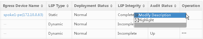
3. You can perform the following operations:
· Click Modify Description to modify description of the LSP.
· Click Modify LSP to modify configurations for the LSP, including paths, outgoing label values, LSP name, and LSP description.
· Click Highlight to highlight all links and nodes for an LSP on the MPLS topology, so that you can intuitively know the devices that the LSP traverses. If the LSP is not complete, for example, some devices are lost, the highlight information might also be incomplete.
· Click Failure Reason to view the reason why an LSP deployment or undeployment has failed. You can only view LSPs whose deployment status is Deployment failed or Undeployment failed.
Viewing detailed information about an LSP
You can view detailed information about an LSP, including the topology diagram, path list, path outgoing interface, incoming interface, outgoing label, incoming label, and the next hop IP address.
To view detailed information about an LSP:
1. Click Service > MPLS Management > LSP Management at the top of the IMC main page.
2. Click an LSP name in the LSP List section of the page.
|
|
NOTE: If an LSP is discontinuous, some of the LSP path sequence numbers are not displayed. On the topology, the discontinuous links of the LSP are displayed as red broken lines. |
Topology Management
With the Topology Management function, you can display the MPLS global network topology, display LSPs between devices, and highlight LSPs.
To access the Topology Management function, click Service > MPLS Management > Topology Management at the top of the IMC main page.
MPLS topology tool bar
To view the topology, you can use the MPLS topology toolbar, as shown in Figure 122.
Figure 122 MPLS topology tool bar
![]()
You can use the following tools to view the topology:
· ![]() Displays the LSP List section on the topology view page, including LSP status and LSP
name. You can also query for existing LSPs by their names.
Displays the LSP List section on the topology view page, including LSP status and LSP
name. You can also query for existing LSPs by their names.
· ![]() Allows you to add
a link on the topology view.
Allows you to add
a link on the topology view.
· ![]() Allows
you to unhighlight a highlighted link.
Allows
you to unhighlight a highlighted link.
Using Topology Management
The Topology Management function provides you with a visual tool to view the MPLS network structure. With the Topology Management function, you can do the following:
· Manage links on the topology.
· Manage devices on the topology.
· Deploy LSPs on the topology.
For more information about managing links on the topology and managing devices on the topology, see H3C Intelligent Management Center v7.3 Enterprise and Standard Platform Administrator Guide.
Highlighting an LSP
To highlight an LSP on the MPLS topology:
1. Click Service > MPLS Management > Topology Management at the top of the IMC main page.
2. To the right of the topology, click the LSP List tab.
3. Enter part or the full name of the LSP that you want to highlight in the Name field, and then click Query. All LSPs that match the query criterion are displayed in the LSP List section of the page.
4. Double-click the LSP that you want to highlight in the LSP List section of the page. The regions, devices, and links between the devices associated with the LSP are highlighted on the topology, and other nodes and links are grayed out.
Viewing an LSP
You can use this function to view an LSP on the MPLS topology, and highlight an LSP between two devices on the MPLS topology.
1. Click Service > MPLS Management > Topology Management at the top of the IMC main page.
2. Press the Ctrl key and select two devices.
3. Click the Display LSP
List icon ![]() on the tool bar. A window
opens, listing all LSPs between the two devices.
on the tool bar. A window
opens, listing all LSPs between the two devices.
4. Select an LSP, and then click OK. The system highlights the selected LSP on the MPLS topology.
Label statistics
With the Label Statistics function, you can display label usage statistics on devices, including the number of static labels being used, number of dynamic labels being used, and the label usage percentage to see which devices have high label utilization, in order to lighten burden for these devices in time. You can also query for a specific device, and view label usage statistics information about the device.
Figure 123 Label Statistics page
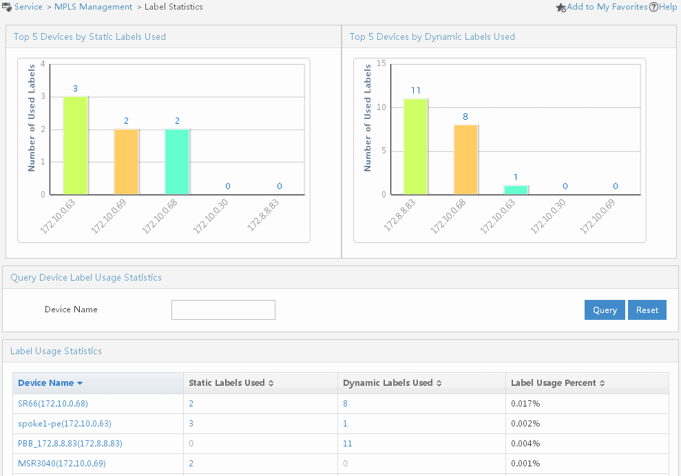
In Figure 123, the Top 5 Devices by Static Labels Used section displays the top 5 devices with the highest static label utilization. The Top 5 Devices by Dynamic Labels Used section displays the top 5 devices with the highest dynamic label utilization. The y-axis indicates the number of used labels, and the x-axis indicates the device names. To view the label usage information for the device that ranks among the top 5 devices by static labels used or dynamic labels used, click the bar chart for the device.
The Label Usage Statistics section of the page displays label usage statistics of devices. The following list gives information for each title in this section:
· Device Name—Indicates the name of the device that uses static label or dynamic label. You can click the name of the device to see detailed information about this device.
· Static Labels Used—Indicates the number of static labels used by the device. You can click a number to see the label usage information in the Label Usage Information section. In this section, you can see label value in the Label column, label type in the Label Type column, and the LSP using this label in the Label Used by column. Click the LSP name in the Label Used by column to see detailed information about the LSP.
· Dynamic Labels Used—Indicates the number of dynamic labels used by the device. You can click a number to see the label usage information in the Label Usage Information section. In this section, you can see label value in the Label column, label type in the Label Type column, and the LSP using this label in the Label Used by column. Click the LSP name in the Label Used by column to see detailed information about the LSP.
· Label Usage Percent—Indicates the percent of label usage.
Querying label usage statistics for a device
To query label usage statistics for a device:
1. Click Service > MPLS Management > Label Statistics at the top of the IMC main page.
2. In the Query Device Label Usage Statistics section of the page, enter part or the full name of the device in the Device Name field, and then click Query. The label statistics of the device are displayed in the Label Usage Statistics section.
3. To clear the query criterion and display the label statistics of all devices, click Reset.
Viewing device label statistics
To view device label statistics:
1. Query label usage statistics for a device. For more information, see "Querying label usage statistics for a device."
2. Click a number in the Static Labels Used column or Dynamic Labels Used column of the device to view the device label usage details, including the LSP that is using the label.
|
|
TIP: To view the label usage information of the device that ranks among the top 5 devices by static labels used or dynamic labels used, click the bar chart of the device in the Top 5 Devices by Static Labels Used section or the Top 5 Devices by Dynamic Labels Used section. |
LSP Traffic Statistics
This function collects and displays the current and long-term LSP traffic statistics. With the statistics, you can observe the LSP traffic trends, learn the LSP running status and performance status, find any bottleneck that impacts the performance, and make better plans for adjusting the existing MPLS network.
The traffic monitoring function allows you to set LSP traffic alert thresholds, set the traffic monitoring status, and view LSP traffic reports.
With the LSP Traffic Statistics function, you can collect and display LSP traffic statistics, set LSP traffic thresholds, and generate LSP outgoing traffic statistics reports from multiple perspectives.
Traffic monitoring information
The TopN LSPs by Outgoing Traffic section provides a bar chart to display the topN (N<=5) LSPs by outgoing traffic. The LSP Monitoring Status Chart section provides a pie chart to display the latest statistics on the number of monitored and unmonitored LSPs. The LSP traffic topN bar chart and the pie chart both support data drilling. You can click the bar chart or pie chart to view detailed LSP traffic and monitoring information.
To view traffic monitoring information:
1. Click Service > MPLS Management > LSP Traffic Statistics at the top of the IMC main page.
2. Click a bar in the TopN LSPs by Outgoing Traffic section to view the traffic report of an LSP.
3. Click a sector in the LSP Monitoring Status Chart section to display the LSP traffic monitoring configuration page.
Setting default thresholds
You can use this function to set default thresholds for outgoing traffic. If the traffic exceeds a threshold, the system generates the corresponding alert information.
1. Click Service > MPLS Management > LSP Traffic Statistics at the top of the IMC main page.
2. Click Default Threshold Settings in the left navigation tree.
3. Click the Modify
icon ![]() to display the Modify Traffic Monitoring
Thresholds page, as shown in Figure 124.
to display the Modify Traffic Monitoring
Thresholds page, as shown in Figure 124.
Figure 124 Modify Traffic Monitoring Thresholds page
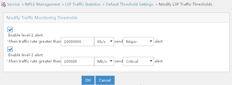
4. Adjust the parameters.
Thresholds include level-1 alert threshold and level-2 alert threshold. You can set the level-2 alert threshold only when the level-1 alert threshold is valid. If the traffic exceeds a threshold, the system generates the corresponding alert information. The level-2 alert severity must be higher than the level-1 alert severity. If the traffic rate drops from the level-2 alert threshold to the level-1 alert threshold, the system generates a recovery message.
Setting LSP traffic monitoring
The LSP Traffic Monitoring page displays all LSPs that can be monitored in the system, LSP type, and monitoring status. You can monitor or unmonitor LSPs. LSP traffic reports are generated for monitored LSPs only.
To query for one or more LSPs for LSP traffic monitoring:
1. Click Service > MPLS Management > LSP Traffic Statistics at the top of the IMC main page.
2. Click LSP Traffic Monitoring in the left navigation tree.
3. Enter query conditions in the Query LSPs pane:
· LSP Name—Indicates the LSP name.
· Audit Status—Indicates the audit status of the LSP. Values include Up, Down, Unknown, Auditing, Testing, Dormant, Not Present, Lower Layer Down, and All.
· Monitoring Status—Indicates the LSP is monitored or not monitored. Values include Monitored, Not monitored, and All.
· LSP Type—Indicates the type of the LSP. Values include Static, Dynamic, CR-LSP, and All.
MPLS Management supports fuzzy query function, which allows you to specify intact or partial query condition.
4. Click Query. All LSPs matching this criteria are displayed in the LSP List section of the page.
5. Select the LSPs whose monitoring status is Not Monitored, and then click Monitor to monitor the selected LSPs, or select LSPs whose monitoring status is Monitored, and then click Unmonitor to stop monitoring the selected LSPs.
6. To clear the query criteria and display all LSPs, click Reset.
|
|
NOTE: An LSP that can be monitored refers to an LSP that has been successfully deployed. The LSP Traffic Monitoring page only displays the deployed LSPs with the auditing status of UP. |
LSP traffic reports
The MPLS Management component supports the query and export of LSP traffic reports. You can view the traffic data of each LSP by viewing the LSP traffic reports. LSP traffic reports display traffic performances and statistics for an LSP in forms of a table, line chart, and bar chart. The default is line chart.
1. Click Service > MPLS Management > LSP Traffic Statistics at the top of the IMC main page.
2. Click LSP Traffic Reports in the left navigation tree.
3. Enter query conditions In the Query Devices pane:
· LSP Name—Indicates the name of the LSP.
· LSP Type—Indicate the type of the LSP. Values include All, Static, Dynamic and CR-LSP.
MPLS Management supports fuzzy query function, which allows you to specify intact or partial query condition.
4. Click Query. All LSPs matching this query criteria are displayed in the LSP Traffic List section.
The following list gives information for each item in the LSP Traffic List:
· LSP Name—Indicates the name of the LSP.
· LSP Type—Indicate the type of the LSP.
· Outgoing Traffic—Indicates the outgoing traffic in bytes per second.
· Operation—Indicates the operation that you can perform on this page.
5. Click the Details
icon ![]() .
.
6. In the Query Criteria section, select one of the following options from the Time Range list.
· Last 1 hour—Specifies a time range of the recent hour. For example, if you select Last 1 hour and the current time is 15:30:30 2006–12–24, the system generates a report displaying the performance data converged during 14:30:30 2006–12–24 to 15:30:30 2006–12–24. The system generates a 5–minute interval data report.
· This day—Specifies a time range from 00:00:00 of the current day to the current time. For example, if you select This day and the current time is 15:30:30 2006–12–24, the system generates a report displaying the performance data converged during 00:00:00 2006–12–24 to 15:30:30 2006–12–24. The system generates a 5–minute interval data report.
· This week—Specifies a time range from 00:00:00 of this Sunday to the current time. For example, if you select This week and the current time is 15:30:30 Friday 2006–12–22, the system generates a report displaying the performance data converged during 00:00:00 Sunday 2006–12–17 to 15:30:30 Friday 2006–12–22. The system generates an hourly report.
· This month—Specifies a time range from 00:00:00 of the first day of the current month to the current time. For example, if you select This month and the current time is 15:30:30 2006–12–24, the system generates a report displaying the performance data converged during 00:00:00 2006–12–1 to 15:30:30 2006–12–24. The system generates an hourly report.
· This year—Specifies a time range from 00:00:00 January 1st of the current year to the current time. For example, if you select This year and the current time is 15:30:30 2006–12–24, the system generates a report displaying the performance data converged during 00:00:00 2006–01–01 to 15:30:30 2006–12–24. The system generates a daily report.
· Customize—Customizes a time range. The system generates a report displaying the performance data converged during the customized time range.
7. Select a display mode in the Outgoing Traffic section.
· Table—Displays the data in a table.
· Line Chart—Displays the data in a line chart.
· Bar Chart—Displays the data in a bar chart.
· Sampling Point—Displays every sampling point in the line chart. To hide the sampling points, click Sampling Point again. You can click the Sampling Point to display the sampling points only when you display data in a line chart.
The following list gives information for each title item:
· Monitored Object—Indicates the LSP that is being monitored.
· Current Value—Indicates the current outgoing traffic value within time range.
· Min. Value—Indicates the minimum outgoing traffic value that has been sampled within time range.
· Max. Value—Indicates the maximum outgoing traffic value that has been sampled within time range.
· Average Value—Indicates the average outgoing traffic value within time range.
· Min. Value Sampled at—Indicates the time when the minimum outgoing traffic value was sampled within time range.
· Max. Value Sampled at—Indicates the time when the maximum outgoing traffic value was sampled within time range.
· Valid Sampling Points—Indicates the number of valid sampling points within time range.
8. On the current page, you can also export the report to different formats: Excel, PDF, HTML, and TXT.
|
|
NOTE: · The system only saves data for the recent year. · Double hyphens in the data table indicate that the system failed to collect any performance data. |
Applications
Scenario
A corporation has two data centers: one primary and one backup. To connect the two data centers at Layer 2 using the MPLS technology, build an MPLS network based on the current network structure, and create a static LSP for label forwarding and label statistics.
The two data centers are connected at Layer 2 through the MPLS network constructed by devices P1, P2, and P3, as shown in Figure 125.
Figure 125 Connecting data centers at Layer 2 by using MPLS
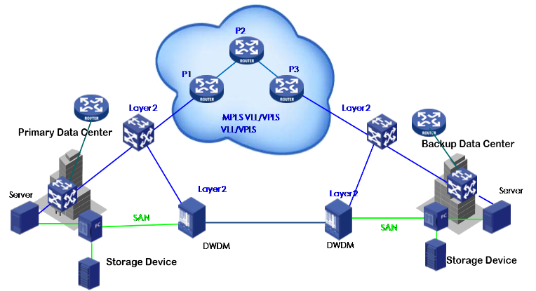
Scenario analysis
To meet the application requirements, you can use the MPLS management component to create and manage the MPLS network. Import P1, P2, and P3 to the MPLS Management, and batch enable MPLS and MPLS LDP for these devices. The system automatically maps out a network topology of the MPLS network constructed by the imported devices. Based on the topology, create and deploy a static LSP. Then, you can view the label usage statistics, learn the LSP traffic statistics, and set LSP traffic thresholds.
Procedure
1. Create an MPLS network.
a. Click Service > MPLS Management > Device Management at the top of the IMC main page.
b. Click the Import Devices button. Import P1, P2, and P3 to the MPLS management. (Assume that the devices are already imported to the IMC platform.)
c. Select P1, P2, and P3 in the Device Management page, and then click the Enable MPLS/LDP button to batch enable MPLS and MPLS LDP for P1, P2, and P3.
2. Create and deploy LSPs.
a. Click Service > MPLS Management > LSP Management at the top of the IMC main page.
b. Click the Add Static LSP button.
c. Click the Manual Deployment tab.
d. In the Topology pane, right click P1 and then click Set as Ingress.
e. Double click the link between P1 and P2, and then double click the link between P2 and P3. In this way, P2 is specified as transit LSR.
f. Right click P3 and then click Set as Egress.
g. Fill in LSP Name and LSP Description.
h. Click the Pre-Allocate Label button. Valid values are assigned to outgoing labels.
i. Click OK.
The path between P1 and P2 can be manually selected, or automatically generated by the system. You can create more static LSPs in the same way.
3. View label statistics.
Click Service > MPLS Management > Label Statistics at the top of the IMC main page. On the page, you can view the top 5 devices by static labels used, top 5 devices by dynamic labels used, and device label usage percentage.
4. View LSP traffic statistics.
a. Click Service > MPLS Management > LSP Traffic Statistics at the top of the IMC main page.
b. Select Default Threshold Settings from the left navigation tree under LSP Traffic Statistics.
c. Set the alert thresholds for outgoing LSP traffic by clicking the Modify icon in the Default Threshold List. Select Enable level-1 alert and enter 10000000 Kb/s as a Major alert. Select Enable level-2 alert and enter 100000 Mb/s as a Critical alert. Click OK.
d. Select LSP Traffic Monitoring from the left navigation tree under LSP Traffic Statistics. Select the newly deployed LSP from the LSP List, and then click the Monitor button in the upper-left corner. The monitoring status changes to Monitored. You can view in real time the top 5 LSPs by outgoing traffic and the LSP monitoring status by clicking Service > MPLS Management from the tabular navigation system.
e. Select LSP Traffic Report from the left
navigation tree under LSP Traffic
Statistics. Query the newly deployed LSP by LSP
name, and then locate and click the LSP Details icon ![]() in the LSP Traffic List. You can view the
latest outgoing traffic statistics and detailed LSP traffic reports in forms of
a table, line chart, and bar chart.
in the LSP Traffic List. You can view the
latest outgoing traffic statistics and detailed LSP traffic reports in forms of
a table, line chart, and bar chart.
FAQ
MPLS VPN Management
Why does the batch process not deal with all selected objects?
Due to server performance capability it times out during the batch process. Therefore it does not deal with the rest after the timeout. If this case happens, contact Hewlett Packard Enterprise to adjust system parameters.
How do I handle the Telnet failure that occurred when I import a device?
· Check whether MPLS VPN Management can communicate with the device normally.
· Check whether Telnet parameters on the platform are consistent with those configured on the device. You can query or modify the parameters through detailed information of the devices on the platform.
How do I handle the PE synchronization failure occurred in global topology or access topology?
· Check whether MPLS VPN Management can communicate with the device normally.
· Check whether Telnet parameters on the platform are consistent with those configured on the device. You can query or modify the parameters through detailed information of the devices on the platform.
· Check whether MPLS VPN Management supports the device version. For details, refer to the version description.
How do I handle the PE-MCE link autodiscovery failure occurred in MCE networking?
· Check whether MCE device is correctly configured, for example, whether an interface of PE is associated with VRF.
· Check whether the MCE is imported correctly.
· Check whether more than two interfaces of MCE are associated with a same VRF, and the IP address of one interface is in the same subnet with one of PE.
Why can't VPNs existing on the network be discovered during auto discovery process?
· The auto discovered PEs do not synchronize the latest VRF configurations of the device.
· Only one PE-CE link belonging to this VPN exists on a VPN network.
· The RT value of the VPN is the same as that of the existing VPN.
How should I add a VPN link in global or access topology?
In global topology, right-click the PE device to select Auto Discovery.
How does import or removal of some HoPEs affect the other HoPEs in a VPN network?
If the imported PEs are not hierarchical, they exist in the VPN as common PEs. Otherwise, the system automatically recognizes PE roles. This rule applies to the removal of PEs, too.
Three types of PEs exist in a VPN: superstratum PEs (SPE), underlayer PEs (UPEs), and middle-level PEs (MPE).
· If you import an SPE and a UPE, they exist as common PEs.
· If you import an SPE and an MPE, or import an MPE and a UPE, they exist as an SPE and a UPE respectively.
· If you import an MPE when an SPE and a UPE exist, these three devices exist as SPE, MPE, and UPE, respectively.
· If an SPE, MPE, and UPE exist in the VPN, and you remove the MPE only, the SPE and UPE become common PEs.
· If an SPE, MPE, and UPE exist in the VPN, when you remove the SPE or UPE, the remaining devices are SPE and UPE, respectively.
How should I discover a complete VPN network in MPLS VPN Management?
When selecting a PE to discover a VPN network, it is recommended that you remove the VPN related to the CEs in the VPN list and select PEs to be synchronized before auto discovery.
Why does an invalid link exist in global access topology after auto discovery is completed?
After auto discovery is completed, if the original VPN link does not belong to any VPN, this link is marked as invalid in global access topology.
The causes for the invalid link might be:
· Association between the interface and VRF on the PE is removed.
· Definition of the VRF associated with the interface on the PE was modified, and the RT value in the new VRF does not belong to any VPN in MPLS VPN Management.
MPLS VPN Management does not manage an invalid link. Therefore, it is recommended that you remove it.
Why can't PC be imported to MPLS VPN Management as a CE?
PEs and CEs managed by MPLS VPN Management must support SNMP. Check whether the PC supports SNMP. If not, you can create a virtual CE to replace the PC and configure a real IP address for the virtual CE interface.
In a VPN with the audit result being Connected, why are PE-Core links displayed as unknown in the topology?
PE-Core links and inter-HoPE links are defined when the devices are being imported and MPLS VPN Management does not support dynamic interface update. You can modify interfaces on PE-Core links and inter-HoPE links.
Why is audit information not displayed when inter-spoke unconnectivity in a Hub-Spoke VPN is audited?
· There are less than two spokes.
· No hub sites exist on the VPN network.
What networking schemes does MPLS VPN Management support?
Currently the following networking schemes are supported: Full-Mesh and Hub-Spoke based on VPN type, VPN with VMCEs, VPN with HoPEs, and VPN with dual-homed CEs based on device roles.
When I deploy a connected link, why is it displayed in red in the topology?
When you associate VPN with a PE interface, the interface automatically becomes down, and generates a Down alarm. Therefore, the IMC considers this link failed.
· If you have configured a PE to send Traps to the IMC, the IMC displays the link as normal because it received an interface up alarm when the interface automatically becomes up.
· If you do not configure the PE to send Traps to the IMC but configured polling interval, the IMC displays the link as normal because it can obtain the real status of the link during the next polling.
· If you do not configure the PE to send Traps to the IMC nor configure polling interval, you can set polling for the PE or manually synchronize the PE to make the link displayed as normal.
Why do only two links at most between AS and PEs appear in the topology?
· If too many links are displayed in a topology, the topology looks disorderly, and it is difficult for you to view the links.
· The system considers the link on the PE enabled with MPLS as a connection to the core network. However, when the PE is a P, there can be many links to other PEs. In this case, the system displays only two of the links to avoid influence on network monitoring. If the two links displayed in the topology are not what you need, you can select either of them, and modify the PE interface connected to the link as the PE interface you want to view. In this way, you can view the link you want to view.
In a PE to CE VPN link information page, both left and right interfaces of the link are all up, but why is the status of this link unknown in topology?
The link status cannot be obtained because one of devices cannot be reached by ping, so the status of this link is unknown.
I am unable to select sub-interfaces of a Cisco router during interface configuration for service deployment. How do I resolve this problem?
Configure VLANs or enable MPLS for the sub-interfaces of the Cisco router and synchronize the device in the MPLS VPN Management.
When I add an SA to a VPN that is monitored, why isn't this SA monitored in this VPN monitor automatically?
The system does not add a new SA to any monitor automatically, and you must do it yourself. When you delete an SA, the system removes it from all the monitors.
Why can't SA be monitored after rebooting a Cisco device?
The interface index is changed after reboot. To prevent this situation, execute the snmp-server ifindex persist command in Cisco devices.
When I add a VPN or SA to monitor, it returns "Interface traffic sampling test failed" or doesn't display a correct status. How do I resolve this problem?
· Check the GET operation on ifTable (ifXTable) through SNMP protocol.
· Try to synchronize PEs in the VPN or SA first, make auto discovery, and then add it to monitor again.
When I import devices to MPLS VPN Management, why can't I see Cisco devices in the Select Device page?
The MPLS VPN Management has no Cisco driver. Contact the technical support center.
Why is the progress information in the device import operation result page incorrect sometimes?
Only one client can perform the device import operation at a time. If two clients perform the operation at almost the same time, they might be able to perform the operation but the progress information cannot show the device import progress correctly. However, the device import operations succeed. In this case, you can view the operation results from the device list.
When several spokes are deployed, why can't these links be discovered?
When the networking scheme is Hub-Spoke, it is necessary to configure both hub and spoke nodes in order to discover valid links.
What should be done if MPLS VPN Management daemon process terminates abnormally, for instance, when power goes off?
Delete all VPNs and PEs in MPLS VPN Management. Import PE again and execute auto discovery.
Why is the audit result of CE-to-CE "unconnective" when CE-to-CE is actually "connective"?
MPLS VPN Management executes connectivity audit when it receives related alarms. Because of a time delay, such as device reboot or instantaneous power down and up, BGP is not steady. In this case audit result might not be correct. If this happens, audit VPN manually.
Why can't MPLS VPN Management discover hierarchy relation in an existing VPN?
MPLS VPN Management cannot discover UPEs in an existing VPN if there are new UPEs added into the VPN network. In this case delete all PEs and execute auto discovery again.
Why can't the auto discover process finish sometimes?
During the automatic discovery process network connection might disconnect occasionally. In this case the auto discovery page cannot receive the auto discovery completion message. Hence it does not finish. If this happens, click the cancel auto discovery link on the page and redo auto discovery again.
Why is there a VPN shown in topology after it has been deleted in the Web page?
The message of VPN deletion is not received by topology due to a network problem. In this case reload the topology tree.
Why do some SA links not belong to any VPN but they are shown as undeployment failure in topology when some SA links are undeployed in a slot?
When you undeploy some SA links in a slot, some fail but their associated VPNs are marked invalid. This is because the system is busy. Undeployment is not completed. In this case remove these SA links manually.
What is the restriction of importing a P device to an AS in MPLS global network topology?
A P device can only exist in one AS.
On a PE device, two VPN instances are configured, associated with two interfaces respectively, and set with the same IP address and mask for the interfaces. When the SA link information of the PE device is viewed on the access topology, why do the IP address and mask of the interface on one of the links are displayed as "N/A"?
The MPLS VPN Management module reads SA link information based on the standard MIB, which requires that the interfaces on the same device cannot have the same IP address. As a result, MPLS VPN Management cannot read duplicate IP address information and displays "N/A" instead. To prevent such problems, do not configure two or more interfaces on a device with the same IP address.
The global topology does not show the links between P devices and PE devices after P devices are imported. How do I resove this problem?
Add links between P devices and PE devices in the topology in either of the following ways:
· Use the Auto Link function in the global topology to add links between P devices and PE devices.
· If the IP address of an interface directly connecting the devices does not have a 30-bit mask, you must manually add links in the topology.
When a VPN or SA is added as the monitor target of a PE interface (which is a VLAN interface), a success message is displayed. Why is the actual operation result a failure?
The traffic monitor function allows you to map one physical interface to only one VLAN interface. Otherwise, the system can give an inconsistent prompt message with the actual monitor status.
In an MCE network, why is the MCE-CE link data different from the actual traffic?
When MPLS VPN Management monitors traffic for an MCE-CE link, it actually monitors the VPN traffic on the sub-interfaces bound to PE-MCE. As a result, the data is different from the actual traffic.
L2VPN Management
What should I do if the configuration comparison result for a PE is Different Config?
This result indicates that the L2VPN configuration maintained in IMC for a PE is different from the L2VPN configuration on the PE. If the configuration on the PE is trustworthy, you can use the auto discovery function of the L2VPN Management to update IMC with the configuration on the PE. If the L2VPN configuration on the PE has errors, log in to the PE to restore the configuration.
MPLS TE Management
If I just configure part of the configuration parameters to add a dynamic RSVP-TE tunnel, what happens?
In the tunnel adding process, the system uses the default settings for the configuration parameters that you do not configure.
How do affinity and affinity mask configurations of a dynamic RSVP-TE tunnel affect the displaying of topology information?
The topology function module displays only topology information that matches the specified affinity and affinity mask when you select to filter topology by affinity.
In the process of adding or modifying dynamic RSVP-TE tunnels, why are the configuration items on the advanced attributes configuration page not always the same?
Some commands for configuring an MPLS TE tunnel are mutually exclusive. For such commands, the system provides the hiding function. If you select one command, the commands exclusive with the command do not appear on the interface.
After I configured FRR protection, the system prompted that the configuration succeeded, but why isn't there a related record in the IMC database?
Because of a time delay, the FRR configuration has not taken effect on the device. Therefore, there is no related record on the device and in the IMC database. It is recommended that you use automatic discovery or perform device synchronization.
During the traffic forwarding configuration process, why did I fail to configure forwarding adjacency after I configured IGP shortcut?
IGP shortcut and forwarding adjacency configurations are mutually exclusive.
In the process of configuring traffic forwarding, IGP shortcut or forwarding adjacency configuration is successful, but why isn't there a related record in the IMC database?
The MPLS TE management can obtain only the configuration currently used by the device. However, the device might not be using the traffic forwarding configuration that you made. Therefore, there is no record of your configuration in the IMC database.
When configuring multiple protection for the same interface, why does the TE management only show information for one protection?
Even though multiple protections are configured, only one protection can be active when tunnel is down. Other protections do not take effect. The TE management only displays the ones that are active.
MPLS Management
Why does the system prompt "Telnet failure" when I import a device?
Analysis: The Telnet parameters on the IMC platform are inconsistent with those configured on the device.
Solution: View and modify the Telnet parameters for the device on the device details page on the IMC platform.
Why does the system prompt "synchronization failure" when I synchronize a device on the Device Management page or in the MPLS topology?
Analysis: Possible reasons for the synchronization failure include device unreachability, inconsistency of Telnet parameters on the IMC platform and those on the device, and device model not being supported by the MPLS management.
Solution: Check and modify the network configuration if needed to make sure the device and IMC can reach each other. View and modify Telnet parameters on the device details page of the IMC platform. See the Release Notes to check whether MPLS Management supports the device model.
Glossary
|
AC |
Attachment circuit. Connects a CE to a PE. It can use physical interfaces or virtual interfaces. Usually, all user packets on an AC, including Layer 2 and Layer 3 protocol messages, must be forwarded to the peer site without being changed. |
|
access topology |
Access topology involves global topology and VPN access topology. Global topology displays the network structure of all VPN resources, including all PEs, CEs, and the AS Core; while the VPN access topology displays network structure of all VPN resources in a VPN. |
|
AS core |
An Autonomous System (AS). It can contain different regions and devices. In the global topology of an MPLS VPN network, AS Core can also represent a network composed of a set of core devices. MVM does not manage the devices in the network. |
|
auto discovery |
Based on VPN resources, auto discovery enables you to discover VPNs and VPN links existing in a network by using the VPN instance RT value of a PE device. |
|
BGP |
Border Gateway Protocol. It establishes signaling sessions through route reflectors (RRs) and supports networking across multiple autonomous systems (ASs). |
|
BGP/MPLS VPN |
Border Gateway Protocol/Multiprotocol Label Switching VPN. Uses BGP to advertise VPN routes and uses MPLS to forward VPN packets on service provider backbones. |
|
BSB |
Blockade State Block. |
|
CE |
Customer edge device. A device directly connected with the service provider network. |
|
CE dual-homing |
A CE router is connected to two Provider Edge (PE) routers, and the binding VRF information of their interfaces connecting to the two CEs belongs to the same Virtual Routing and Forwarding (VRF) instance. |
|
CLNP |
Connectionless network protocol. A datagram network protocol, it provides the same underlying service to a transport layer as IP. |
|
configuration audit |
Compare the latest configuration that MVM synchronized from the device with the device configuration saved in the MVM. The results are displayed in the PE device list and the network topology. |
|
configuration changed |
Compare the latest configuration that MVM synchronized from the device with the device configuration saved in the MVM. If they are not consistent, the device is considered to be configuration changed. |
|
connectivity audit |
Connectivity between CEs in the same VPN is audited and the connectivity or unconnectivity between CEs is listed in detail. (Inter-Spoke connectivity is not audited by default, unless otherwise specified.) |
|
customized group |
With this function, you can divide VPNs into manageable groups. |
|
CPE-based |
Customer premises equipment-based. |
|
export RT |
Export RT defines which sites can receive VPN-IPv4 routes. A local PE sets this type of VPN target attribute for VPN-IPv4 routes learned from directly connected sites before advertising them to other PEs. See RT. |
|
FEC |
Forwarding Equivalence Class. A technique used for controlling errors in data transmission over unreliable or noisy communication channels. See RT. |
|
full-mesh network |
A full mesh network has a fully connected mesh topology. For a VPLS VPN network, it means that every PE on the network has a direct connection to every other PE on the network, logically. |
|
full-mesh |
In this networking scheme, each site contains a group of RT attributes with values of Import RT and Export RT being the same, and all sites are hub sites. |
|
H-VPLS network |
In an H-VPLS network, all NPE devices are fully meshed logically, and a UPE device establishes a virtual connection with only the nearest NPE device. |
|
HoPE |
Hierarchy of PE. MVM includes three types of HoPEs: SPE, MPE, and UPE, with no limit on the number of levels. A one-level PE is called a general PE, a two-level HoPE includes SPE and UPE. If there is a three-level HoPE or a HoPE with more than three levels, the lowest level is UPE, the highest is SPE, and the PEs in the middle are MPEs. |
|
hub-spoke |
In this networking scheme, the site in the center is called the hub site, which knows routes to all the other sites in the same VPN. The sites that are not in the center are called spoke sites, from which traffic reaches the destination through the hub site. This type of networking scheme is called Hub-Spoke networking. |
|
import RT |
Import RT defines from which sites a PE can receive routes. A PE checks the Export RT of VPN-IPv4 routes advertised by other PEs. If the Export RT matches the Import RT of the VPN instance, the PE adds the routes to the VPN routing table. See RT. |
|
IPX |
Internet packet exchange. |
|
IS-IS |
Intermediate System to Intermediate System. A routing protocol designed to move information efficiently within a network. |
|
L2VPN manager |
Layer 2 VPN manager. |
|
LDP |
Label Distribution Protocol. An MPLS signaling protocol, which is in charge of classifying FECs, distributing labels, and establishing and maintaining LSPs. |
|
LDP session |
LDP sessions are established between LSRs based on TCP connections and are used to exchange messages for label binding, label releasing, and error notification. |
|
LER |
Label Edge Router. A router that operates at the edge of a Multiprotocol Label Switching network. |
|
link invalid |
If association lost or RT value change on a VPN link results in the link not belonging to the original VPN, MVM considers it invalid. |
|
LSP |
Label Switched Path. An LSP is the path along which packets of a FEC travel through an MPLS network. |
|
LSR |
Label Switching Router. An LSR is a fundamental component on an MPLS network. LSRs support label distribution and label swapping. |
|
management VPN |
A management VPN is a VPN with Hub-Spoke networking scheme, and it can manage user-end CEs. |
|
MCE |
Multi-VPN-Instance CE. A router that has Multiple VPN-Instances, running in an Intranet. |
|
MPE |
Middle level PE. The device connects a UPE and an SPE in an HoPE architecture. |
|
MPLS |
Multiprotocol Label Switching. MPLS is critical to the implementation of MPLS traffic engineering, and supports explicit LSP routing. |
|
MPLS TE |
MPLS Traffic Engineering. MPLS TE combines the MPLS and traffic engineering technologies. By establishing LSP tunnels along specific paths, it supports reserving resources to best utilize network resources and avoid non-even load distribution. When network resources are insufficient, MPLS TE allows bandwidth-hungry LSPs and critical user traffic to occupy the bandwidth for lower priority LSP tunnels. In case an LSP tunnel fails or congestion occurs on a network node, the path backup and Fast Reroute (FRR) features that MPLS TE provides can reroute traffic to a backup path for forwarding. |
|
MPLS VPN |
Multiprotocol Label Switching Virtual Private Network. |
|
MPLS VPN configuration synchronization |
The latest VRF configuration and VRF routing information on a PE are obtained, deciding whether the VRF configuration in MVM has changed. |
|
MVM |
MPLS VPN Manager. |
|
non-managed CE |
A CE device in a VPN. It maps to an actual existing but unmanageable CE device. |
|
NPE |
Network provider edge. A device that functions as the network core PE. An NPE resides at the edge of a VPLS network core domain and provides transparent VPLS transport services between core networks. |
|
OSPF |
Open Shortest Path First. |
|
P |
Provider Router. A backbone router on a service provider network and not directly connected with any CE. It only needs to be equipped with MPLS capability. |
|
PBB |
Provider Backbone Bridge. A set of architecture and protocols for routing over a provider's network, allowing interconnection of multiple Provider Bridge Networks without losing individually defined VLANs. |
|
PE |
Provider edge. A device connecting one or more CEs to the service provider network, mainly for access to VPN services. A PE maps and forwards packets between private networks and public network tunnels. A PE can be a UPE or NPE. |
|
peer |
Two LSRs using an LDP session to exchange FEC-label bindings are peers. |
|
PW |
Pseudo wire. The bidirectional virtual connection between two VSIs. A PW consists of two unidirectional virtual circuits (VCs). |
|
RD |
Route Distinguisher. An address field prefixed to a specific IPv4 address, making VPN IPv4 prefixes globally unique. |
|
region |
Network devices that belong to the same area are assigned to the same region to facilitate management. A region can contain up to ten levels of sub-regions. |
|
RSVP |
Resource Reservation Protocol. RSVP is designed for Integrated Service (IntServ). It reserves resources on each node along a path. RSVP operates at the transport layer but does not participate in data transmission. It is an Internet control protocol similar to ICMP. |
|
RSVP-TE |
RSVP Traffic Engineering extension protocol. RSVP-TE is an extension to the RSVP. It supports MPLS label distribution and allows resource reservation information to be transmitted with label bindings. It can be used as a signaling protocol for LSP tunnel setup in MPLS TE. |
|
RT |
Route Target. BGP/MPLS uses the 32-bit BGP extended community attributes called VPN target attributes, or route target attributes, to control the advertisement and receipt of VPN routing information.VPN RT attributes define which sites can receive VPN-IPv4 routes, and from which sites a PE can receive routes. |
|
SA |
Service Access. Equals to a PE-CE link, indicating an access from a CE in the VPN. |
|
SC |
Service Community. The basic element in constructing a VPN, including Full-Mesh and Hub-Spoke networking schemes. If multiple SCs exist in a common station, they can form a VPN together. |
|
service topology |
Logical structure of all VPN links in a VPN, including links between CEs and CEs, with CEs including managed CEs and unmanaged CEs. |
|
site |
A group of IP systems with IP connectivity being implemented without relying on any service provider network. |
|
SOA |
Service Oriented Architecture. |
|
SPE |
Superstratum PE (SPE) or Service Provider-end PE. The device is connected to the core device in an HoPE architecture. |
|
spoke |
In Hub-Spoke networking scheme, the sites that do not reside on the core are called spoke sites. Packets from these sites reach the destination through the hub node. |
|
TE |
Traffic Engineering. The process of steering traffic across the network backbone to enable efficient use of available bandwidth between two routers. |
|
TCP |
Transmission Control Protocol. |
|
UPE |
User Facing-Provider Edge. A device that functions edge device that functions as the user access convergence device. In a HoPE architecture, the device connecting the user network is called an underlayer PE (UPE) or user-end PE. |
|
VDPN |
Virtual Dialup Private Network. Extends remote access to a private network using a shared infrastructure. |
|
VLL |
Virtual Leased Line. A point-to-point virtual leased line technology. |
|
VMCE |
A VLAN isolation of MCE (VMCE). A CE device connecting multiple PEs and CEs. |
|
VPLS |
Virtual private LAN service. Provides multipoint to multipoint communication over IP/MPLS networks. |
|
VPN |
Virtual Private Network. A set of sites. VPN is used to set up private dedicated networks over the public network. |
|
VPN Link |
A link for a user-end network to connect to an MPLS VPN network, that is, a PE-CE link. For a network that has MCEs, it is an MCE-CE link. |
|
VPN networking schemes |
VPN networking schemes include Hub-Spoke and Full-Mesh based on VPN network types and include VPN network with MCEs, with HoPEs and with dual-homed CEs based on device roles. |
|
VRF |
VPN Routing and Forwarding instance. Allows multiple instances of a routing table to co-exist within the same router at the same time. |
|
VSI |
Virtual switch instance that maps actual VPLS access links to virtual links. |
