- Table of Contents
- Related Documents
-
| Title | Size | Download |
|---|---|---|
| 01-Text | 3.05 MB |
Exploring the BIMS Overview page
Managing CPE additional information
Adding CPE additional information
Modifying CPE additional information
Deleting CPE additional information
Configuring the inform interval
Configuring the polling interval
Configuring the file transfer type
Setting an auto restore strategy
Configuring duplicate IP check
Managing a CPE Interaction Log
Viewing a CPE Interaction Log list
Querying a CPE interaction log
Adding or modifying CPE groups
Adding a subgroup to a CPE group
Removing CPEs from a CPE group
Overview of the zero-configuration CPE deployment wizard
Managing configuration templates
Querying and viewing configuration templates
Organizing configuration templates
Creating a configuration template
Modifying a configuration template
Copying a configuration template
Exporting a configuration template
Deleting a configuration template
Querying and viewing CPE software
Importing CPE software to BIMS
Configuring baseline CPE software
Deploying configurations and software using the Deployment Guide
Automatically deploying CPE configurations
Automatically deploying CPE software
Querying and viewing deployment task list
Viewing deployment task details
Viewing execution results of a deployment task
Executing a deployment task immediately
Suspending/resuming a deployment task
Managing CPE configurations using Configuration Center
Querying and viewing CPE configuration list
Deploying CPE software using Configuration Center
Deploying CPE configurations using Configuration Center
Backing up a CPE configuration
Restoring a CPE configuration by time
Querying and viewing backup tasks
Enabling or disabling a backup task
Managing backup history records
Viewing the Backup History List
Running a check task immediately
Enabling or disabling a check task
Checking task execution results
Viewing the check task history list
Viewing compliance policy check results
Refreshing the task history list
Viewing the compliance policy list
Viewing compliance policy details
Modifying the compliance policy list
Deleting the compliance policy list
Enabling/disabling the compliance policy
Querying and viewing CPE class list information
Adding or modifying a CPE class
Querying alarms from the All Alarms page
Recovering alarms from the All Alarms page
Deleting alarms from the All Alarms page
Editing maintenance experience
Managing message notifications
Adding or modifying alarm definitions
Mobile branch device management
Service provider view management
Viewing mobile branch device information
Switching update status for a mobile branch device
Viewing the mobile branch topology
Viewing the topology of a location view
Managing configuration templates
Deploying mobile branch device configurations and software
Viewing the performance management list
Querying SIM card performance information
Viewing detailed SIM card performance information
Setting signal strength thresholds for a SIM card
Branch Device Flow Statistic Report
Branch Device Inventory Report
CPE Connectivity Counts Report
CPE Connectivity Detail Report
CPE Connectivity Summary Report
Device Flow Monthly Statistic Report
Device Flow Year Statistic Report
Device Signal Strength Monthly Statistic Report
Device Signal Strength Year Statistic Report
Device Up Down Time Period Report
Device Up Duration Monthly Statistic Report
Device Up Duration Year Statistic Report
Inactive Device Statistic Report
One Device Flow Monthly Statistic Report
One Device Flow Year Statistic Report
One Device Signal Strength Monthly Statistic Report
One Device Signal Strength Year Statistic Report
One Device Up Duration Monthly Statistic Report
One Device Up Duration Year Statistic Report
Phone Signal Strength Detail Report
Phone Signal Strength Summary Report
Branch Device Flow Statistic Report
Branch Device Inventory Report
CPE Connectivity Detail Report
CPE Connectivity Summary Report
Device Flow Monthly Statistic Report
Device Flow Year Statistic Report
Device Signal Strength Monthly Statistic Report
Device Signal Strength Year Statistic Report
Device Up Down Time Period Report
Device Up Duration Monthly Statistic Report
Device Up Duration Year Statistic Report
Inactive Device Statistic Report
One Device Flow Monthly Statistic Report
One Device Flow Year Statistic Report
One Device Signal Strength Monthly Statistic Report
One Device Signal Strength Year Statistic Report
One Device Up Duration Monthly Statistic Report
One Device Up Duration Year Statistic Report
Phone Signal Strength Detail Report
Phone Signal Strength Summary Report
Prerequisites of BIMS applications
Example 2: Deploying CPE configurations through a USB flash drive
Example 3: Deploying CPEs in branch offices
Example 4: BIMS working cooperatively with IVMS
Example 5: Using CPE additional information
Example 6: Using Compliance Center
Introduction to BIMS
The H3C IMC Branch Intelligent Management System (BIMS) supports the TR-069 protocol for remote management of end-user devices. TR-069 is based on the DSL Forum technical specification, CPE WAN Management Protocol, for communications between Customer-Premises Equipment (CPE) and Auto Configuration Servers (ACS).
Network managers, engineers, and operators face challenges in their mission to manage various CPE devices in a centralized way. BIMS is a comprehensive management platform that meets these challenges. Relying on high reliability, flexibility and scalability, BIMS maintains CPE-vendor neutrality, enabling seamless switching from one CPE to another, while managing all CPEs on a single platform.
In addition, BIMS supports a distributed deployment function. Because you can install the BIMS module on a server that does not have the IMC platform installed, it enables you to break through the performance obstacles of the IMC server station.
BIMS capabilities
BIMS includes the following functions:
· Resource Management
· CPE Group
· Configuration Management
· Compliance Center
· System Configuration
· BIMS Alarms
· Mobile Branch Management
· BIMS Reports
You can access the first five functions through the BIMS navigation tree, and the last three from the Alarm and Report tabs, respectively.
Resource Management
BIMS provides a comprehensive resource management function for managing CPE devices from HP, H3C, and other manufacturers.
You can use this function to monitor and manage many aspects of a CPE device. You can add, configure, monitor or manage one or more CPE devices at a time. You can add CPE devices manually, or by importing existing local CPE files. In addition, the Batch Operate function enables you to configure CPE operations in batches. All communication messages between CPE and BIMS are recorded in the CPE Interaction Logs.
CPE Group
You can organize CPE resources into different groups and subgroups, enabling you to more efficiently manage a network of CPE devices. You can further enhance your network security by assigning different authorities to CPE groups.
Configuration Management
BIMS provides a central configuration and management function to facilitate managing and deploying the CPE configuration files (or segments) and software. The configuration management portal integrates:
· Managing configuration templates
The configuration template library provides unified management of configuration files and segments. You can customize your own, or import configuration files or segments to the configuration template library, to easily manage and deploy CPE configurations.
· Managing CPE software
The software library enables you to import CPE software from your local client into BIMS to deploy the software on one or more CPEs. In addition, you can manage CPE software through querying, modifying, exporting, and deleting functions.
· Deploying CPE configurations and software to CPEs by using Deployment Guide
The Deployment Guide is a wizard that helps you deploy the configuration templates and software stored in BIMS to the CPEs. You can use it to customize deployment tasks for the CPEs managed by BIMS. You can also create automatic deployment tasks for virtual CPEs not yet managed by BIMS. When the virtual CPEs pass the BIMS authentication for the first time, BIMS deploys the configurations or software to them immediately.
· Managing deployment tasks
BIMS implements CPE configuration deployment and software deployment using deployment tasks. You can use this function to view the deployment status and results. You can also drill down into the step-by-step details for every CPE in a deployment task, and identify which CPE failed a deployment and why.
· Managing CPE configurations through the Configuration Center
The Configuration Center helps you quickly query, back up, and view CPE configurations and software upgrade history. You can also use it to make a configuration file or a version of CPE software as a baseline. You can restore the current configuration or software to the baseline as needed.
· Backing up CPE configurations
You can use the Backup Configuration function to create and manage tasks for backing up CPE configuration. In addition, you can manually back up the configuration at any time.
· Managing backup history records
You can use this function to view details and results of all historical backup records of a backup task.
· Comparing CPE configurations
You can use this function to compare two configuration files.
Compliance Center
Compliance Center can help you check every target CPE device or CPE class using a binding configured compliance policy. Once it finds a CPE that violates the compliance policy, Compliance Center shows you the violation details in multiple ways. You can then fix the illegal configuration segment items, and solve the potential configuration and security risks in the network. Also, you can generate the check results to a report automatically, allowing you to examine the check results in detail at any time.
System Configuration
You can use the System Configuration function to configure:
· System settings, including web management, polling and inform intervals, CPE access parameters, common password status, and ACS running log settings.
· Authentication users.
· CPE devices by class.
· The Optional Tool for converting between DHCP Option 43 and an ACS URL.
Alarms Management
The alarm or event management system in BIMS uses the existing CPE device database of IMC and couples it with sophisticated trap processing to generate alarms. These alarms notify operators and support organizations when a CPE device has a communications problem, or is in violation of system standards. The alarms management function provides rules you can define to generate events and alarms. These rules define Realtime Alarms, All Alarms, Alarm Notification, and Alarm Definition parameters so you can optimally manage your CPE network.
Mobile Branch Management
With Mobile Branch Management (MBM), BIMS can centrally manage mobile branch devices. Mobile branch devices are CPEs with SIM cards installed. The management procedure is as follows:
1. Deploy SMS to the devices through MBM. The devices go online in MBM and BIMS when they are powered on.
2. Deploy configuration and software to the devices through BIMS.
3. Manage groups of mobile branch devices in BIMS. You can view their location information, real-time performance data, and performance statistics.
Report Management
In the Report tab, you can find template driven reports for BIMS elements.
BIMS reports provide performance statistics and real-time performance data about CPEs. As a subcomponent of BIMS, MBM provides performance statistics reports for the SIM cards and mobile branch devices.
They are generated from system-defined or user-defined templates. You can view web-based reports, or export them to Crystal Reports, Adobe Acrobat, Microsoft Excel, Microsoft Word, Rich Text, or Comma Separated Value formats. In addition, you can set a report schedule and have the results sent through e-mail in any of these file formats.
Before installing BIMS
Before installing the BIMS module, make sure you have completed the following tasks:
· Install and deploy IMC on your server station.
· Learn about using the IMC Platform according to H3C Intelligent Management Center Enterprise and Standard Platform Administrator Guide.
|
|
NOTE: The installation and deployment procedures for BIMS are similar to other IMC service components. To use MBM, you must select the MBM subcomponent when you install and deploy BIMS. For more information, see H3C IMC deployment guides. |
Accessing BIMS
To log on to IMC:
1. Enter the URL for the IMC server in your browser, including the port number for IMC:
¡ http:// servername:portnumber /imc
¡ https:// servername:portnumber /imc
Where server name is the name of the IMC server, and port number is the TCP port assigned to IMC Basic during installation.
Alternatively, you can use the IP address of the server instead of the server name.
2. Enter your account in the Operator field.
3. Enter your password in the Password field.
4. Select a mode:
¡ To access the classic edition of BIMS, select Classic. By default, classic edition is selected. The classic edition uses the conventional IMC style to organize and display service modules. You cannot change the organization.
¡ To access the Web desktop edition of BIMS, select Desktop. The Web desktop edition manages and displays service modules as individual applications. You can organize applications as needed.
5. Click Login or press Enter.
Web desktop management
Web desktop edition of BIMS manages and displays service modules as individual applications. You can create multiple desktops to organize different types of applications. For example, create one desktop for security applications and create another desktop for network applications. You can also add one application to different desktops. The following information describes the procedure to add BIMS applications to a desktop. For more information about other desktop management procedures, see H3C Intelligent Management Center Enterprise and Standard Platform Administrator Guide.
To add a BIMS application to a Web desktop:
1. Access a Web desktop.
2. Click the Add
Application icon ![]() .
.
The Add Application window appears.
3. Filter applications by group name or application name:
¡ Select Branch Intelligent Management System from the Group Name list.
All applications in the group are displayed.
¡ Enter a complete or partial name in the Application Name field, and then click Query.
All matching applications are displayed.
If the application list spans multiple pages, the following navigational aids appear:
¡ Click
![]() to page forward
in the application list.
to page forward
in the application list.
¡ Click
![]() to page forward
to the end of the application list.
to page forward
to the end of the application list.
¡ Click
![]() to page backward
in the application list.
to page backward
in the application list.
¡ Click
![]() to page backward
to the front of the application list.
to page backward
to the front of the application list.
4. Click Add Application for the application you want to add to the Web desktop.
|
|
NOTE: You can add an application to different desktops. Existing indicates that the application already exists in the current desktop and cannot be added again. |
Exploring the BIMS Overview page
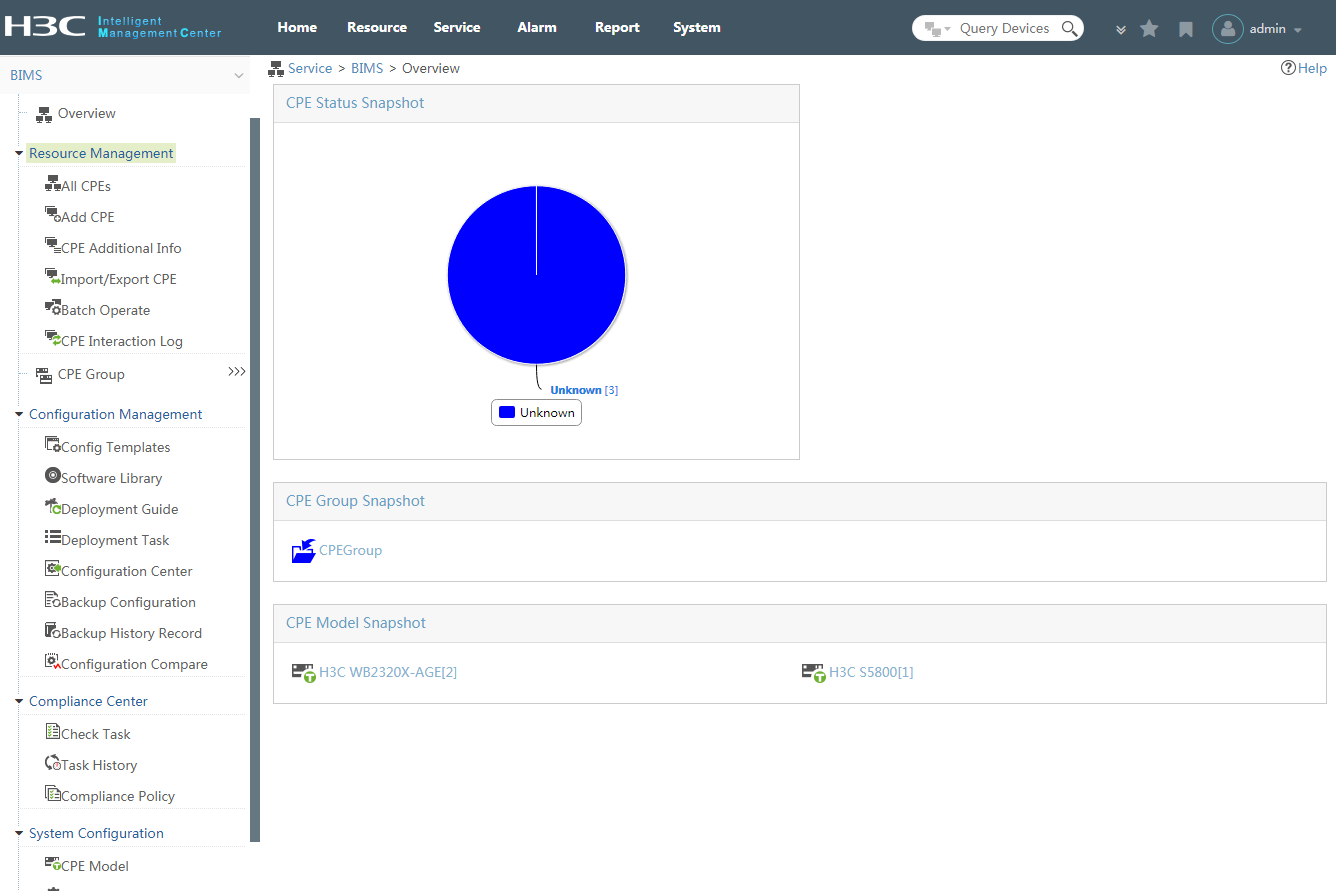
Figure 1 introduces you to the BIMS Overview page in the IMC user interface.
The expandable menu on the left is the
Navigation Tree, which enables you to quickly browse to any other BIMS
function. If you click the Overview icon ![]() on
the top of the tree, the Overview page displays. When you first log in, no data is available on the
default Overview page. After you add CPE devices to BIMS, the system generates
statistics immediately, and displays them on the Overview.
on
the top of the tree, the Overview page displays. When you first log in, no data is available on the
default Overview page. After you add CPE devices to BIMS, the system generates
statistics immediately, and displays them on the Overview.
There are three function panes on the Overview page:
· CPE Status Snapshot—Displays CPE status by showing the ratio of each severity level. You can open the All CPEs List page by clicking the pie chart, which shows you the CPE details.
· CPE Group Snapshot—Displays all CPE groups in a hierarchical folder view so you can quickly navigate to a specific CPE group.
· CPE Model Snapshot—Displays all CPE classes in a hierarchical folder view so you can quickly navigate to a specific CPE class.
You can open the All CPEs page by clicking the target CPE class, and you can open the Subgroup/CPE List page by clicking the specific CPE group name.
BIMS workflow introduction
Figure 2 shows the recommended workflow for using BIMS to manage and deploy CPE configurations.
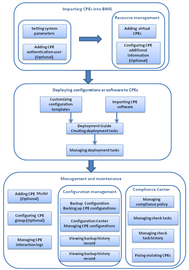
Workflow description:
1. Importing CPEs into BIMS:
a. Plan your CPE authentication and deployment strategies, and set BIMS system parameters according to these strategies.
When a CPE sends a connection request to BIMS, BIMS checks whether the connection username and password in the request matches the related information configured in the authentication user or BIMS common password. You must add authentication users or configure the common password in advance.
b. Add or import virtual CPEs to BIMS.
If the Adding CPE automatically function is enabled, you do not need to add virtual CPEs manually. For more information, see "Managing system settings."
2. Deploying configurations or software to CPEs:
a. Prepare the resources for CPE deployment, which includes customizing configuration templates and importing CPE software.
b. Using Deployment Guide, create deployment tasks for deploying configuration files (segments) or software to the specified CPEs.
c. Using Deployment Task, view the status and execution results of deployment tasks.
3. Managing and maintaining BIMS, including:
¡ Adding CPE classes
¡ Configuring a CPE group for CPE classification
¡ Managing CPE interaction logs
¡ Managing CPE configurations
This includes managing, backing up, restoring, and comparing the configurations of deployed CPEs.
¡ Performing compliance checks
This includes defining compliance policies and checking whether any CPE devices or CPE classes violate the corresponding compliance policy. You must then fix the violating CPE by revising the illegal configuration segment items, and deploying the corrected configuration to the target CPE.
|
|
IMPORTANT: If a CPE that is not behind NAT accessed BIMS, BIMS can access the CPE to manage it. In this case, the HTTP service must be enabled for the CPE to serve as an HTTP server. |
Resource management
IMC provides a resource management function for recognizing CPE devices from the network and adding them into BIMS, including adding a CPE, adding CPEs in batches, and importing or exporting CPEs. BIMS enables you to provision a CPE or collection of CPEs based on basic information and additional information. The provisioning mechanism enables CPE provisioning at the time of initial connection to the broadband access network, and then provides the ability to manage or configure at any subsequent time.
BIMS can securely identify a CPE or a group of CPEs, and establish the initial connection with them. The interactions log between IMC BIMS and CPE is recorded, which is convenient for monitoring the communication status. Also, BIMS provides a function for exporting the CPE information as a CSV file for further use. Meanwhile, you can import an existing CSV file so that BIMS can add the CPEs accordingly.
The BIMS component can manage mobile branch devices as CPEs. The administrator can add device information about a mobile branch device to MBM, which synchronizes the device information to BIMS. When SMS is deployed, the mobile branch device comes online in MBM and BIMS, and can be managed as a CPE in BIMS.
Managing CPE devices
Viewing all CPEs
1. Click Service > BIMS > Resource Management> All CPEs.
The All CPEs page displays all available CPEs in the CPE List with the following information:
¡ Status—The most severe unrecovered alarm level for this CPE. The Unknown status indicates that the CPE is a virtual CPE.
¡ CPE Name—The CPE name, which is set to OUI + Serial by default. You can customize this when adding the CPE. Click the CPE name to open the specific CPE Details page.
¡ NAT CPE—If the CPE is behind NAT.
¡ Serial ID—The CPE serial ID number.
¡ CPE Model—The CPE class.
¡ IP Address—The IP address of the CPE device.
¡ Operation—Accesses the operation list. Click to open the list, and then click to select the following target operations:
- IP Ping Test—Test if the connection between CPE and BIMS is available by pinging a fixed IP address.
- Open Web Manager—Open the CPE web manager.
- Remote Reboot—Execute a remote reboot of the CPE from BIMS.
- Factory Reset—Reset the CPE configuration to default values.
- Configuration Management—Open the CPE Configuration Management page.
For more information about each operation item, see "Configuration Management"
2. Select the boxes for the target CPEs in the CPE List, and then click one of the following buttons to perform a batch operation:
¡ Delete—Delete the CPEs.
¡ Synchronize—Synchronize the configuration information shown on BIMS with the CPEs.
¡ IP Ping Test—Launch the IP ping test procedure to test if the connections between the current CPEs and other devices are available.
¡ Remote Reboot—Reboot the CPEs.
¡ Factory Reset—Reset the configurations of the CPEs to the factory default value.
¡ Synchronize System Name—Synchronize the system names of the CPEs with their device labels.
3. Customize the columns displayed in the CPE List.
a. Click Customize Columns in the upper right corner of the CPE List list.
The Customize Columns window appears. The following columns can be customized:
- NAT CPE
- Serial ID
- CPE Model
- Vendor
- IP Address
- Last Inform Time
- Sync Result
- Software Version
- Access IP
b. Select the columns to be displayed and click OK. The selected columns and the collected data are displayed in the CPE List.
In the CPE List, the Status, CPE Name, and Operation columns are required. The NAT CPE, Serial ID, CPE Model, and IP Address columns are displayed by default.
Querying a CPE
1. Click Service > BIMS > Resource Management >All CPEs.
2. On the All CPEs page, specify the following query conditions in the Query CPE pane:
¡ CPE Name
¡ CPE Model
¡ Vendor
¡ Software Version
¡ Serial ID
¡ CPE Status
¡ IP Address
¡ Access IP
BIMS supports fuzzy matching, which allows you to specify an intact or partial query condition.
For more information about the query conditions, see "Viewing all CPEs."
3. Click Query.
The query results display in the CPE List.
4. Click Reset to reset the query conditions.
Adding a CPE
BIMS provides two methods for adding a new CPE device:
· Manually adding a CPE—Select this solution when you want to enter the CPE information one by one. In this mode, you must enter all CPE basic information items manually.
· Quickly adding CPEs—Select this solution when you want to add batches of CPEs with the same OUI, CPE Class, or CPE Group. In this mode, these three parameters are assigned the same values as the previous CPE. You only need to specify the Serial ID and CPE Name values by using a barcode scanner instead of entering them manually.
|
|
NOTE: The new CPE in the list has an initial state of Unknown. This means the CPE is only a virtual CPE that has not built a real connection with BIMS yet. After the CPE is successfully connected to and verified by BIMS, it becomes an available CPE that can be managed by BIMS. For more information, see "Configuration Management." |
Manually adding a CPE
1. Click Service > BIMS > Resource Management > Add CPE.
2. On the Add CPE page, specify the following parameters in the Basic information and Additional information areas:
¡ Basic information—The authentication type you select affects the parameters displayed in this area. Specify the parameters by following the instructions in this table:
|
Parameter |
Instruction |
Parameter |
Instruction |
|
Authentication Type |
Select OUI + Serial ID. |
Authentication Type |
Select ACS UserName. |
|
CPE Name |
Enter the CPE name. |
CPE Name |
Enter the CPE name. |
|
OUI |
Enter the OUI of the vendor. The OUI should be six hexadecimal characters. |
ACS URL |
Enter the ACS URL. |
|
Serial ID |
Enter the CPE serial ID. |
ACS Username |
Enter the ACS username. It must be unique in BIMS, and be the same as the ACS username on the CPE. |
|
ACS Username |
Enter the ACS username. It must be the same as the ACS username on the CPE. |
ACS Password Generated |
Select one of the following modes: · Automatically Generated—The system automatically generates the ACS password. Select this mode if you want to deploy the CPE configuration by using a USB flash drive. · Manual Input—If you select this mode, configure the following parameters: ¡ ACS Password—Enter the ACS password. It must be the same as the ACS password configured on the CPE. ¡ ACS Confirm Password—Enter the ACS password again. |
|
ACS Password |
Enter the ACS password. It must be the same as the ACS password configured on the CPE. |
||
|
ACS Confirm Password |
Enter ACS password again. |
||
|
CPE Model |
Select a CPE class from the list. |
CPE Model |
Select a CPE class from the list. |
|
CPE Group |
Select a CPE group. This item is available only when you have already added a CPE group. |
CPE Group |
Select a CPE group. This item is available only when you have already added a CPE group. |
¡ Additional information—The customized additional information appears only when it was previously added. For more information about the additional information function, see "Adding CPE additional information."
3. Click OK.
The CPE that you added appears in the CPE List.
Quickly adding CPEs
1. Click Service > BIMS > Resource Management > Add CPE.
2. On the Add CPE page, click Quickly Add CPE.
3. On the Quickly Add CPE page, specify the following settings:
¡ Serial ID—Enter the serial ID of the CPE, or use a scan gun to scan the CPE serial ID. For the scan gun to read the serial ID, place the cursor in the Serial ID field.
¡ OUI—Enter the organizationally unique identifier of the vendor. The OUI should be six hexadecimal characters.
¡ CPE Name—Enter the CPE name, or accept the default.
¡ CPE Model—Select a CPE model from the CPE Model list.
¡ CPE Group—Specify a CPE Group. By default, no CPE group is specified.
4. Click OK.
After the CPE is added, the system retains all settings on the page except the serial ID and CPE name. You can add additional CPEs without specifying the OUI, CPE class, or CPE group.
5. Click Cancel to quit the adding procedure.
Modifying a CPE
1. Click Service > BIMS > Resource Management > All CPEs.
2. On the All CPEs page, select the target CPE from the CPE list, and then click the CPE name.
3. On right side of the CPE Details page, click Modify CPE Name in the Apply pane to modify the CPE name.
|
|
NOTE: The modify function is only available for virtual CPE devices. |
Deleting one or more CPEs
1. Click Service > BIMS > Resource Management > All CPEs.
2. On the All CPEs page, select one or more target CPEs in the list.
3. Click Delete.
Managing CPE details
Use the CPE details page to manage comprehensive CPE configuration items. Links to this page appear in the Basic Information and Additional Information panes. You can check the alarm status from the statistics chart in the CPE Details and the Recent 10 unrecovered alarms panes. You can also perform management tasks in the Action, Apply, and Configuration Management panes.
Viewing CPE details
1. Click Service > BIMS > Resource Management > All CPEs.
2. On the All CPEs page, click the target CPE name in the CPE List.
3. Check the following basic information for the CPE:
¡ CPE Name—Name of the CPE in BIMS. Click Edit to modify the name of the CPE in BIMS. The change does not apply to the CPE side.
¡ System Name—The system name for a CPE device, which is used to mark a device in the network. By default, the device type is used as the system name.
¡ Access Type—The access type of the CPE.
¡ NAT CPE—If the CPE is behind NAT.
¡ Status—The most severe unrecovered alarm level for the CPE.
¡ IP Address—The CPE IP address.
¡ Vendor—The CPE device vendor information.
¡ OUI—The organizationally unique identifier number of the vendor.
¡ Serial ID—The CPE serial ID number.
¡ CPE Model—The CPE model.
¡ Software Version—The software version of the CPE.
¡ Hardware Version—The hardware version of the CPE.
¡ Runtime—How long the CPE has been in operation.
¡ Last Inform Time—When the latest synchronization process occurred.
¡ Sync Result—Whether the synchronization process succeeded or failed.
¡ CPE Description—The user-defined CPE description.
¡ ACS IP—The IP address at which BIMS provides ACS services for the CPE.
¡ Working Mode—CPE operating mode. Options are gateway mode and device mode.
¡ CPE Group—Group to which the CPE belongs.
4. If you have added additional information, Additional Information and Modify appear on the page. You can click Modify to modify the information.
5. Use the alarm diagram to identify the alarm count for each severity level, except for the informational severity.
Configuration Management
Six items are displayed in the Configuration Management pane. It is important for you to check the following information on the CPE Details page:
· Latest Configuration Backup at—When the latest configuration backup occurred.
· Automatically Backup Period—Details of the automatic backup cycle. If you have not yet configured an automatic backup period, you can add an auto backup task by clicking the link. For more information, see "Creating a backup task."
· Latest Startup Configuration Backup—The file name of the latest startup configuration backup file. Click the file name to open the Configuration File Details page, where you can check all the details of the startup configuration file.
· Latest Running Configuration Backup—The file name of the latest running configuration backup file. Click the file name to open the Configuration File Details page, where you can check all the details of the running configuration file.
· Current Software—The current running software version.
· Latest Available Software for Upgrade—The latest available software version that can be used for upgrade.
If you want to check more details about the configuration backup history and the software deployment history, click Configuration History in the upper right corner of the Configuration Management pane. For more information, see "Managing backup history records."
Recent 10 unrecovered alarms
The ten latest unrecovered alarms are displayed in the Recent 10 unrecovered alarms pane. You can check the alarm level, description, and alarm raised time. If you want to check more alarms, click the more in the upper right corner of the Recent 10 unrecovered alarms pane. For more information about BIMS alarms, see "CPE alarm management."
Available actions
The Action pane contains the following items:
· Refresh—Refresh the page.
· Delete—Delete the associated CPE device.
· Synchronize—Synchronize the configuration information shown in BIMS with the CPE device.
· IP Ping Test—Launch an IP ping test to test the connectivity between the CPE and other devices. This action is not supported for CPEs in device mode.
a. On the IP Ping Test page, configure the following parameters:
- Timeout—Specify the response timeout timer in seconds. Connectivity is not available if no response has been received before the timer expires.
- IP Packets Size—Specify the size of the ICMP packets.
- Number—Specify the number of IP ping tests.
- DSCP—Specify the DSCP value in the ICMP packets.
- Host—Specify the destination IP address. By default, this field displays the IP address of the ACS.
- Interface—Specify the Layer 3 interface that the CPE uses to communicate with the destination device.
b. Click Test to launch the test process.
The test results appear on the IP Ping Test Results page.
· Open Web Manager—Click to open the CPE web manager.
Apply options
The Apply pane contains entries for you to modify CPE attributes. A CPE operating in device mode does not support the following entries:
· WAN DSL Link
· WAN IP Connection
· WAN PPP Connection
· Remote Reboot
· Factory Reset
· Roll Back Configuration By Force
Modify CPE Name
To modify the CPE name:
1. Click the Modify CPE
Name icon ![]() .
.
2. Enter a new name in the Modify CPE Name dialog box, and then click OK.
Modify Polling Interval
To modify the polling interval:
1. Click the Modify
Polling Interval icon ![]() .
.
2. Enter the status polling interval in the Status Poll Interval field.
The value range is 1 to 600 minutes, and the default is 5 minutes.
BIMS determines the reachability of a CPE as follows:
¡ For a CPE not behind a NAT device, BIMS sends HTTP requests. The CPE is reachable if BIMS receives HTTP responses.
¡ For a CPE behind a NAT device, BIMS calculates the interval between the current time and the last access from the CPE. The CPE is reachable if the interval is shorter than the Inform interval.
3. Enter the configuration polling interval in the Configuration Poll Interval field.
The value range is 60 to 1500 minutes, and the default is 120 minutes. This interval determines the amount of time BIMS waits before polling managed CPEs for any configuration changes.
4. Click OK to accept the polling interval configuration.
Modify Access Parameters
For BIMS to access the CPE, make sure BIMS uses the same CPE username and password as the CPE.
To modify access parameters:
1. Click the Modify Access
Parameters icon ![]() .
.
2. Enter new parameters in the Modify Access Parameters dialog box.
If you want to apply the modification to the CPE, select Apply to CPE. If the BIMS and the CPE use different user names or passwords, the process fails.
3. Click OK.
Modify CPE Configuration
To modify a CPE configuration:
1. Click the Modify CPE
Configuration icon ![]() .
.
The Modify CPE Configuration page appears.
2. Configure the following attributes:
¡ ACS URL—Specify the ACS URL to which the CPE initiates a new connection.
¡ ACS Username—Specify the user name for authentication to the ACS URL.
¡ ACS Password—Specify the password for authentication to the ACS URL.
¡ Periodic Inform Status—Enable or disable the CPE to periodically send Inform messages to the ACS.
¡ Periodic Inform Interval—Specify the interval for the CPE to automatically send Inform messages to the ACS. By default, the interval is 600 seconds.
¡ Periodic Inform Time—Specify the time
at which the CPE sends an Inform message. Enter the time in the yyyy-mm-dd
hh:mm:ss format. Alternatively, click the Calendar icon![]() , and then select a
date and time.
, and then select a
date and time.
This page also displays the CPE attributes, including CPE Name, Vendor, OUI, Serial ID, CWMP, and Connection Request URL. These attributes are not configurable on this page.
3. Click OK.
Modify File Transfer Type
To modify file transfer type:
1. Click the Modify File
Transfer Type icon ![]() .
.
2. Select HTTP or HTTPS in the Modify File Transfer Type dialog box, and then click OK.
Data Model
To view the data model:
1. Click the Data Model
icon ![]() to open the data model
page. For more information, see "Configuring the data model."
to open the data model
page. For more information, see "Configuring the data model."
WAN DSL Link
To view the WAN DSL link:
1. Click the WAN DSL Link
icon ![]() .
.
The WAN DSL Link Management page appears.
2. Specify the query conditions in the Query WAN DSL Link pane, and then click Query.
The WAN DSL Link list displays all matching WAN DSL link information.
WAN DSL Link List contents
¡ Enable Status—Whether the DSL link is enabled or disabled.
¡ Link Type—DSL link type. Options include EoA, IPoA, PPPoA, PPPoE, and CIP. This field displays Unconfigured if the link type is not specified.
¡ Link Status—DSL link status for the most recent poll. Options include Up, Down, Initializing, and Unavailable.
¡ Destination Address—Destination address of the DSL link.
3. Click the Refresh button to update the WAN DSL link list.
WAN IP Connection
To view the WAN IP connection page:
1. Click the WAN IP
Connection icon ![]() .
.
The WAN IP Connection page appears.
2. Specify the query conditions in the Query WAN IP Connection pane, and then click Query.
The WAN IP Connection List displays all matching WAN IP connections.
WAN IP Connection List contents
¡ Connection Name—Name of the WAN IP connection. Click the name to view connection details.
¡ Connection Type—Options include Unconfigured, IP Routed, and IP Bridged.
¡ Connection Status—Options include Connected and Unconnected.
¡ Address Type—IP address assignment method. Options include DHCP and Static.
¡ External IP Address—The external IP address used for NAT.
¡ Default Gateway—Default gateway IP address. The IP address is displayed if the address type is Static.
WAN PPP Connection
To view the WAN PPP connection page:
1. Click the WAN PPP
Connection icon ![]() .
.
The WAN PPP Connection Management page appears.
2. Specify the query conditions in the Query WAN PPP Connection pane, and then click Query.
The WAN PPP Connection List displays all matching PPP connections.
WAN PPP Connection List contents
¡ Connection Name—Name of the WAN IP connection. Click the name to view connection details.
¡ Connection Type—Options include IP Routed, DHCP Spoofed, PPPoE Bridged, PPPoE Relay, PPTP Relay, and L2TP Relay.
¡ Connection Status—Options include Connected and Unconnected.
¡ NAT Enable—Status of NAT.
¡ External IP Address—The external IP address used for NAT.
¡ Remote IP Address—The remote IP address of the connection.
Remote Reboot
To execute a remote reboot from BIMS, click
the Remote Reboot icon ![]() .
.
Factory Reset
To reset the CPE configuration to the factory
defaults, click the Factory Reset icon ![]() .
.
Change CPE
To change a CPE:
1. Click the Change CPE
icon ![]() to
replace the old CPE with a new one.
to
replace the old CPE with a new one.
2. Instead of configuring the new CPE, you can just specify the OUI and Serial ID. Then BIMS matches all configurations of the old CPE to this new one. The new CPE will work as the previous one.
Roll Back Configuration By Force
To roll back the CPE configurations to the
latest archive configuration file by force, click the Roll
Back Configuration By Force icon ![]() .
.
This function is available only if you apply the Roll Back When CPE Connection Fails item when deploying the configuration. In addition, the CPE device must support automatic, regular backup of the configuration. For more information, see "Deploying CPE configurations."
|
|
NOTE: Make sure the CPE device supports the configuration automatic backup function before executing Roll Back Configuration By Force. |
Managing CPE additional information
In addition to basic information, BIMS provides an additional information function, which allows customized information for marking the CPE device. For example, this can be position information or parameter values. In addition, you can use the additional information function to assign parameter values directly when you deploy configuration templates, or deploy configurations to the CPE in batches. For more information about how to deploy configurations by using additional information, see "Deploying configurations and software using the Deployment Guide."
Adding CPE additional information
1. Click Service > BIMS > Resource Management > CPE Additional Info.
2. On the CPE Additional Information page, click Add.
3. On the Add CPE Additional Information page, complete the following:
¡ Field Name—Specify the additional information name.
¡ Variable Name—Specify a variable name for the CPE additional information, which is used for deploying the configuration.
¡ Allow Null—Select this option if the variable value can be null.
¡ Field Type—Specify a type for the field. The available values are Integer and Any Characters.
¡ Default Value—Specify a default value for the additional information.
¡ Maximum Value—Specify the maximum value for the variable.
¡ Minimum Value—Specify the minimum value for the variable.
4. Click OK.
Modifying CPE additional information
The CPE additional name information cannot be modified. To modify other CPE additional information parameters:
1. Click Service > BIMS > Resource Management > CPE Additional Info.
2. On the Add CPE
Additional Information page, select the target CPE, and then click the Modify icon ![]() .
.
3. On the Modify CPE Additional Information page, update the parameter values.
4. Click OK.
Deleting CPE additional information
1. Click Service > BIMS > Resource Management > CPE Additional Info.
2. On the CPE Additional
Information List page, click the Delete icon
![]() to delete the additional information for a specific
CPE.
to delete the additional information for a specific
CPE.
Exporting or importing CPEs
You can use the exporting CPE file function to export the existing CPE information from BIMS to a separate file, which is convenient for backing up and reusing the CPE information.
You can use the importing CPE file function to modify the CPE basic and additional information items in batches from a local Excel file, which avoids modifying them one by one in IMC. BIMS assigns new values for each item during the importing process.
Exporting a CPE file
1. Click Service > BIMS > Resource Management > Import/Export CPE.
2. On the Import/Export CPE page, click Export.
3. On the Download File page, click CPE Exporting Result.
The file save page appears.
4. Save the file to your local path.
Importing a CPE file
1. Click Service > BIMS > Resource Management > Import/Export CPE.
2. On the Import/Export CPE page, click Import CPE to activate the import file load menu.
3. Click Browse.
The Choose file to load page appears.
4. Select the target import file, click Open, and then click Import to load the CPE file into BIMS.
The Import page appears. Both the Basic Information and the Additional Information are displayed in this page.
|
|
NOTE: The import process fails if the import file does not meet the legal parameter and order. The legal parameter and order are CPE Name, Serial ID, OUI, Vendor, CPE Class, System Name, Access Type. The Basic information cannot be modified on the import page during the import process. However, it can be assigned as your additional information value from the target column of the import file by using the list. |
5. Click OK to launch the importing process.
The CPE Importing Results page appears, where you can check the import results.
6. Click Back to end the importing process.
Configuring CPEs in batches
You can use the Batch Operate function to configure CPE parameters in batches, which avoids accessing the CPE details page to do the configurations one by one.
Configuring the inform interval
This function enables you to set the interval at which the system polls the specified CPEs. The system reads the configuration of the specified CPEs at the interval, and updates the system database.
To configure the inform interval in batches:
1. Click Service > BIMS > Resource Management > Batch Operate.
2. On the Batch Operate page, click Configure Inform Interval.
3. On the Periodic Inform Interval page, click Add CPE.
4. On the CPE List page, select the target CPEs, and then click OK.
5. Specify an Inform interval for all target CPEs, and then click Apply.
With periodic inform enabled, the inform interval (an integer in seconds) is the interval at which the CPE tries to connect to the ACS, and invokes the inform method.
Configuring the polling interval
To configure the polling interval in batches:
1. Click Service > BIMS > Resource Management > Batch Operate.
2. On the Batch Operate page, click Configure Polling Interval.
3. On the Configure Polling Interval page, click Add CPE.
4. On the CPE List page, select the target CPEs, and then click OK.
5. Specify a Status Polling Interval and Configuration Polling Interval for all target CPEs, and then click Apply.
With periodic inform enabled, the inform interval (an integer in seconds) is the interval at which the CPE tries to connect to the ACS and invokes the inform method.
Configuring access parameters
To configure the access parameters in batches:
1. Click Service > BIMS > Resource Management > Batch Operate.
2. On the Batch Operate page, click Configure Access Parameters.
3. On the Configure Access Parameters page, click Add CPE.
4. On the CPE List page, select the target CPEs, and then click OK.
5. Specify the Connection Request Username and Connection Request Password for all target CPEs, and then click Apply.
The Connection Request Username and Connection Request Password are used to initiate a connection request to the CPE from the ACS. The password read from the CPEs is a null string rather than the actual value.
Configuring the file transfer type
This function sets the protocol to HTTP or HTTPS for multiple CPEs in batches. The protocol is used for transferring files between the specified CPE and the BIMS server. The default protocol is HTTP.
To configure the file transfer type in batches:
1. Click Service > BIMS > Resource Management > Batch Operate.
2. On the Batch Operate page, click Configure File Transfer Type.
3. On the Configure File Transfer Type page, click Add CPE.
4. On the CPE List page, select the target CPEs, and then click OK.
5. Specify the Transfer Type as HTTP or HTTPS, and then click Apply.
Setting an auto restore strategy
This function enables the automatic restoration of the configuration or software to the baseline version for multiple CPEs in batches. For more information, see "Deploying configurations and software using the Deployment Guide."
To set the auto restore strategy in batches:
1. Click Service > BIMS > Resource Management > Batch Operate.
2. On the Batch Operate page, click Set Auto Restore Strategy.
3. On the Set Auto Restore Strategy page, click Add CPE.
4. On the CPE List page, select the target CPEs, and then click OK.
5. Select whether to enable the Auto Restore Configuration and Auto Restore Software functions, and then click OK.
Configuring IP ping test
To configure the IP ping test in batches:
1. Click Service > BIMS > Resource Management > Batch Operate.
2. On the Batch Operate page, click IP Ping Test.
3. On the IP Ping Test page, complete the following parameters:
¡ Timeout—Specify the timeout period in seconds. If the response time is over the limit, the test result is Failed.
¡ IP Packets Size—Specify the IP packets size.
¡ Number—Specify the number of IP ping packets that BIMS sends during one ping test.
¡ DSCP—Specify the DSCP value of the IP packet.
¡ Host—Specify the source host address.
4. Click Add CPE.
5. On the CPE List page, select one or more target CPEs, and then click OK.
BIMS enables you to ping several different CPEs from the host at the same time.
6. Click Test to launch the test process.
The test results appear on the IP Ping Test Results page.
Configuring the data model
BIMS provides the data model as a mechanism for sending and receiving parameter information from the CPE.
Two ways to open the data model page are:
· Configuring the data model for a single CPE by clicking the Data Model icon on the CPE Details page. There is no need to select a CPE in this mode, you only need to select a target operation, and then the results are displayed on the Operation Result pane.
· Configuring the data model in batches.
To configure the data model in batches:
1. Click Service > BIMS > Resource Management > Batch Operate.
2. On the Batch Operate page, click Data Model.
The Data Model page appears.
3. In the CPE List
pane, click the Select CPE icon ![]() .
.
4. On the CPE List page, specify the querying conditions, and then click Query, or click Query directly to list all CPEs.
The available CPEs appear under the CPE List pane of the Data Model page.
5. Select one or more target CPEs by clicking the associated check boxes, and then select a target parameter from the InternetGatewayDevice folder.
6. Right-click the parameter, and then, on the operation menu, complete the following:
¡ Get Parameter Values—Select this option to get the parameter value information from the CPE.
¡ Get Parameter Attributes—Select this option to display the parameter attributes information from the CPE.
¡ Set Parameter Values—Enter the parameter values in the Operation Result pane, and then click Set Parameter Values to apply them immediately.
¡ Set Parameter Attributes—Enter the parameter attributes in the Operation Result pane, and then click Set Parameter Attributes to apply them immediately.
¡ Parameter Information—Select this option to display the parameter details in the Operation Result pane.
All operation results are displayed in the Operation Result pane.
Configuring duplicate IP check
To configure duplicate IP check in batches:
1. Click Service > BIMS > Resource Management > Batch Operate.
2. On the Batch Operate page, click Duplicate IP Check.
3. Enter the description for the target interfaces in the Interface Description field.
Select Fuzzy if you want to enter a partial interface description.
Select Exact if you want IMC to find an exact match for the interface description you have entered.
4. Select the CPEs that contain the interfaces you want to check:
¡ To check all CPEs managed by BIMS, select the Network-Wide Check.
¡ To check the specified CPE, clear the Network-Wide Check option, and click Add CPE. On the CPE List page, select one or more target CPEs, and then click OK.
5. Click OK to launch the test process.
The test results appear on the Duplicate IP Check Result page.
Managing a CPE Interaction Log
An Interaction Log is a system record generated automatically by BIMS. It records the communication history between BIMS and CPEs, including CPE request messages, file upload notifications, and other configuration messages.
Viewing a CPE Interaction Log list
1. Click Service > BIMS > Resource Management > CPE Interaction Log.
All interaction logs are displayed in the CPE Interaction Log list, which contains the following information:
¡ CPE Name—The CPE name, which is set to OUI + Serial ID by default. The name can be customized when adding a CPE. Click this link to open the CPE Details page.
¡ OUI—The organizationally unique identifier number of the vendor.
¡ Serial ID—The CPE serial ID number.
¡ IP Address—The IP address of the CPE.
¡ Operation Time—When the interaction log occurred.
¡ Description—The operation details.
Querying a CPE interaction log
1. Click Service > BIMS > Resource Management > CPE Interaction Log.
2. On the CPE Interaction Log page, complete the following query conditions in the Query CPE Interaction Log pane:
¡ CPE Name
¡ Description
¡ Start time
¡ End time
¡ IP Address
BIMS supports fuzzy matching, which allows an intact or partial query condition.
3. Click Query to launch the query procedure.
4. Click Reset to reset the query conditions.
CPE group management
A CPE group facilitates rights assignment to operators. You can create CPE groups, and add related CPEs to each CPE group for management.
CPE groups are classified as follows:
· Root group—Functions like a root directory. An administrator can assign the management right of a root group to other operators.
· Subgroup—Functions like a subdirectory.
If an operator has the management right on a root group, then the operator also has the management right on all subgroups of the root group. Both types of groups can contain CPEs and subgroups.
|
|
NOTE: · Only an administrator can add, modify, and delete CPE groups. · An operator can manage multiple CPE groups. A CPE group can be managed by multiple operators. · Only an administrator can view the ungrouped CPEs. · A CPE group can have multiple levels of subgroups, like the folder system of Windows. · The status of a CPE group is determined by the status of the CPE with the highest severity level in the CPE group and subgroups. · If there is no CPE in a CPE group, the status of the CPE group is Unmanaged. |
To open the CPE Group Details page:
1. Click Service > BIMS > CPE Group.
The CPE Group page appears.
2. Click the active link in the Group Name field in the CPE Group List.
The CPE Group Details page displays the following information:
· Basic Info of Device Group contains:
¡ Group Name—The name of the CPE group.
¡ Description—A description of the CPE group.
· Operators contains:
¡ Login Name—An operator's login name.
¡ Full Name—An operator's full name.
¡ Role—An operator's role: administrator, maintainer, or viewer.
¡ Manage All Groups—Whether the operator has management access to all groups.
¡ Description—A description of the operator.
· CPE List lists all subgroups and CPEs within the selected CPE group. It contains:
¡ Status—The status of the associated subgroup or CPE as:
- Normal—The CPE group is working normally.
- Suspended—The CPE group has stopped working.
- Unmanaged—The CPE group is currently not being managed.
¡ Subgroup/CPE Name—The name of a subgroup or CPE.
¡ Serial ID—The serial ID of a CPE.
¡ Class—The class of a CPE.
¡ Vendor—The vendor of a CPE.
¡ IP Address—The IP address of a CPE.
Adding or modifying CPE groups
You can add or modify:
· A root CPE group
· Subgroups in a CPE group
· CPEs in a CPE group
Adding a root CPE group
1. Click Service > BIMS > CPE Group.
2. On the CPE Group page, click Add on the top of the CPE Group List.
3. Enter the CPE Group Name and Description under Basic Info of Device Group.
4. Select operators who can manage the CPE group from the Operators list.
5. Click OK.
Modifying a CPE group
1. Click Service > BIMS > CPE Group.
2. On the CPE Group
page, in the root CPE Group List, click the Modify icon ![]() of the CPE group you
want to modify.
of the CPE group you
want to modify.
3. Modify the CPE group Description and the Operators.
|
|
NOTE: The CPE Group Name cannot be modified. |
Adding a subgroup to a CPE group
1. Do one of the following to open the Subgroup/CPE List page of a CPE group:
¡ Click Service > BIMS > Overview, and then locate and click the link of a CPE group in the CPE Group Snapshot section to open the Subgroup/CPE Name list page of the CPE group.
¡ Click
Service > BIMS > CPE Group, and then click the CPE
List icon ![]() to open the Subgroup/CPE
Name List page of the
associated CPE group.
to open the Subgroup/CPE
Name List page of the
associated CPE group.
¡ On the Subgroup/CPE Name List page of a CPE group, click a subgroup name to open the Subgroup/CPE Name List page of the selected subgroup.
2. Click Add Subgroup in the upper-right corner of the Subgroup/CPE Name List.
The dialog for adding a subgroup appears.
3. Enter the name and description for the subgroup. The subgroup name must be unique in a directory.
4. Click OK.
Adding a CPE to a CPE group
1. Click Service > BIMS > CPE Group.
2. On the CPE Group
page, click the CPE List icon ![]() .
.
3. On the Subgroup/CPE Name List page of the associated CPE group, click Add in the upper left corner of the Subgroup/CPE Name List.
4. On the CPE Query page, enter search criteria, and then click Query.
5. Select one or more CPEs from the search results list, and then click OK.
Moving CPEs to a group
1. Perform one of the following tasks to open the Subgroup/CPE List page of a CPE group:
¡ Click Service > BIMS > Overview, and then locate and click the link of a CPE group in the CPE Group Snapshot section to open the Subgroup/CPE Name List page of the CPE group.
¡ Click
Service > BIMS > CPE Group, and then click the CPE
List icon ![]() to open the Subgroup/CPE Name List page of the associated CPE group.
to open the Subgroup/CPE Name List page of the associated CPE group.
¡ On the Subgroup/CPE Name List page of a CPE group, click a subgroup name to open the Subgroup/CPE Name List page of the selected subgroup.
2. Select one or more CPEs from the Subgroup/CPE Name List.
3. Click Move to Group in the upper left corner of the Subgroup/CPE Name List.
The Move to Group window appears.
4. Select a CPE group from the CPE Group List.
5. Click OK.
Deleting CPE groups
You can delete:
· A root CPE group
· A subgroup in a CPE group
· CPEs from a CPE group
|
|
NOTE: Deleting a CPE group also deletes all the subgroups of the CPE group. |
Deleting a root CPE group
1. Click Service > BIMS > CPE Group.
2. On the CPE Group
page, click the Delete icon ![]() of a CPE group.
of a CPE group.
3. Click OK.
Removing a CPE subgroup
1. Do one of the following to open the Subgroup/CPE Name List page of a CPE group:
¡ Click Service > BIMS > Overview, and then locate and click the link of a CPE group in the CPE Group Snapshot section to open the Subgroup/CPE Name List page of the CPE group.
¡ Click
Service > BIMS > CPE Group, and then click the CPE
List icon ![]() to open the Subgroup/CPE Name List page of the associated CPE
group.
to open the Subgroup/CPE Name List page of the associated CPE
group.
¡ On the Subgroup/CPE Name List page of a CPE group, click a subgroup name to open the Subgroup/CPE Name List page of the selected subgroup.
2. Click the Remove icon ![]() of a CPE subgroup entry. A dialog box appears for confirmation.
of a CPE subgroup entry. A dialog box appears for confirmation.
3. Click OK.
Removing CPEs from a CPE group
1. Navigate to the group or subgroup CPE List containing the CPE you want to remove.
2. Do one of the following:
¡ Locate
and click the Remove icon ![]() of a CPE entry, and
then click OK.
of a CPE entry, and
then click OK.
¡ Select one or more CPE entries in the CPE Group List, click Remove in the upper left corner of the list, and then click OK.
Configuration management
BIMS provides central configuration and management functions to facilitate managing and deploying the CPE configuration files (or configuration segments) and CPE software. The Configuration Management function enables you to:
· Manage configuration templates, including:
¡ Customizing your own, or importing configuration files or configuration segments to the configuration template library.
¡ Deploying a configuration file or configuration segment on one or more CPEs.
¡ Managing configuration files or configuration segments through querying, modifying, copying, exporting, and deleting functions.
· Manage the CPE software library including:
¡ Importing CPE software to the CPE software library.
¡ Deploying software on one or more CPEs.
¡ Managing CPE software through querying, modifying, exporting, renaming, and deleting functions.
· Deploy CPE configurations and software to CPEs using the Deployment Guide.
With this function, you can customize deployment tasks for the CPEs that are managed by BIMS. For virtual CPEs, which are not managed by BIMS currently, you can create automatic deployment tasks for them. When the virtual CPEs pass the BIMS's authentication for the first time, BIMS deploys the configurations or software to them immediately.
· Manage deployment tasks
BIMS implements CPE configuration and software deployment using deployment tasks. The deployment task feature enables you to view the deployment status and results. Also, you can manage CPE configuration and software deployment through task control functions, such as suspending, running, resuming, and deleting operations.
· Manage CPE configurations through the Configuration Center
The Configuration Center helps you quickly query the current configurations of a CPE, back up the configuration files of a CPE, and view the CPE configuration and software upgrade history. In addition, the Configuration Center enables to you to specify a configuration file or a version of CPE software as the baseline. You can restore the current configuration or software to the baseline as needed.
· Back up CPE configurations
The Backup Configuration center enables you to create and manage backup tasks that perform CPE configuration backup. You can create a periodical backup task to back up the configurations of specified CPEs as scheduled. In addition, this function enables you to manually back up the configuration at any time.
· View historical backup records of a backup task
· Compare CPE configurations
With this function, you can compare the configurations of different CPEs, or compare two configurations that are deployed to the same CPE.
In addition, BIMS provides a zero-configuration CPE deployment wizard, with which BIMS can automatically add a CPE, and deploy an initial configuration to the CPE when it accesses BIMS for the first time. For more information, see "Typical BIMS applications."
Overview of the zero-configuration CPE deployment wizard
You can directly configure and deploy CPEs from the IMC BIMS client without performing any operations on CPE devices. This is called a zero-configuration solution. As a best practice, use the zero-configuration solution to effectively manage a large-scale network containing many CPEs, such as a data center, or to manage remote CPEs, such as those in enterprise branches.
BIMS provides a zero-configuration CPE deployment wizard, as shown in Figure 3, that integrates all zero-configuration CPE deployment related operations. This wizard makes the workflow and related operations fast, visual, and easy. You can import, configure, and deploy one or more CPEs without visiting multiple configuration rooms or using complicated command lines.
Figure 3 Zero-configuration CPE deployment wizard
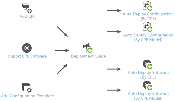
To perform a zero-configuration deployment:
1. Add CPE to BIMS—In a zero-configuration solution, when a new CPE accesses your network, it first requests a dynamic IP address from the DHCP server. When assigning a dynamic IP address for the CPE, the DHCP server also sends the BIMS IP address and related information to the CPE. Then, the CPE acknowledges the IP address of BIMS and sends an access request to BIMS. BIMS authenticates the CPE and decides whether to add the CPE to BIMS. For more information, see "Adding a CPE."
|
|
NOTE: If the Adding CPE automatically function is enabled, you do not need to add virtual CPEs manually. For more information, see "Managing system settings." |
2. Import CPE software—Import CPE software to the CPE software library. For more information, see "Importing CPE software to BIMS."
3. Add a CPE configuration file or segment—Add a CPE configuration file or segment to the configuration template library. For more information, see "Creating a configuration template."
4. Deploy CPE configuration—Create a deployment task to deploy a configuration file or segment to the specified CPEs. For more information, see "Deploying CPE configurations" and "Automatically deploying CPE configurations."
5. Deploy CPE software—Create a deployment task to deploy CPE software to the specified CPEs. For more information, see "Deploying CPE software" and "Automatically deploying CPE software."
To open the zero-configuration CPE deployment wizard:
1. Click the Service tab.
2. From the navigation tree, select BIMS > Configuration Management.
The zero-configuration CPE deployment wizard opens.
3. View the flowchart, shown in Figure 3, and then click each operation icon to open the corresponding operation interface.
Managing configuration templates
BIMS uses a configuration template library to store and manage CPE configuration files or segments. In BIMS, all configuration files or segments are generated by creating a configuration template operation. The configuration templates are managed in hierarchy, beginning from the folder in the root directory. This enables you to add new folders as needed to classify your configuration templates.
Querying and viewing configuration templates
To query and view configuration templates:
1. Click Service > BIMS > Configuration Management > Config Templates.
The configuration templates and folders stored at the template folder root level are displayed in the Configuration Templates list. The list provides the following information:
¡ Name—The name of a configuration template or folder.
- The name of a configuration template appears with a Template icon ![]() . Click the name to open the Configuration Template Details page.
. Click the name to open the Configuration Template Details page.
- The name of a configuration folder appears with a Folder icon ![]() . Click the name to view all configuration templates and subordinate
folders stored in it.
. Click the name to view all configuration templates and subordinate
folders stored in it.
¡ Type—Whether the entry is a configuration file, segment, or folder.
¡ Creation Time—The date and time the configuration template or folder was created.
¡ Description—A description of the configuration template or folder.
¡ Operation—Click the Operation icon ![]() to display an operation list, which contains the following operation
links:
to display an operation list, which contains the following operation
links:
- Modify—Use to modify an existing configuration template or folder. For more information, see "Modifying a configuration template folder" and "Modifying a configuration template."
- Delete—A Delete icon ![]() . You can click the icon to delete a configuration template or
folder. For more information, see "Deleting a configuration template folder" and "Deleting a configuration template."
. You can click the icon to delete a configuration template or
folder. For more information, see "Deleting a configuration template folder" and "Deleting a configuration template."
|
|
NOTE: You cannot delete the Default Folder because it contains all system-defined configuration segments. When you delete a user-defined folder, you delete all configuration templates and subordinate folders stored in the target folder at the same time. |
- Copy—Use to copy an existing configuration template for reuse purposes or moving it to a new location. For more information, see "Copying a configuration template."
- Export—Use to export a configuration template to the local client in plain text. For more information, see "Exporting a configuration template."
- Deploy—Use to launch the Deployment Guide for deploying CPE configurations to the specified CPEs. For more information, see "Deploying CPE configurations."
2. You can set query criteria by name, template type, and the stored folder, to search for the configuration templates or folders you want to view. Specify the query conditions in the Query Condition pane, and then click Query.
The configuration templates or folders matching the query conditions are displayed in the Configuration Templates list.
3. Click Reset to restore all configuration templates and folders stored at the template folder root level.
4. Click Refresh to view the latest Configuration Templates list.
Organizing configuration templates
BIMS enables you to create a multilevel directory structure as needed for classifying, organizing, and managing configuration templates. Template configuration folders work exactly the same way as folders or directories in file systems, allowing you to create folders at the root level and nested within folders.
The two types of configuration template folders are:
· System-defined folder—The Default folder is the only system-defined folder in the Configuration Templates list. The Default folder, located at the root level, is used to store the system-defined configuration templates. You cannot add or import a configuration template to the Default Folder, or modify or delete this folder.
· User-defined folder—You can create, modify, or delete a user-defined folder, and add configuration templates to a user-defined folder.
Creating a configuration template folder
You must have administrative level access to create configuration template folders.
To create a new template folder:
1. Click Service > BIMS > Configuration Management > Config Templates.
The configuration templates and folders stored at the template folder root level are displayed in the Configuration Templates list.
2. Navigate to the parent folder where you want to store the new folder.
3. Click Add Folder in the upper right corner of the Configuration Templates list.
The Add Folder dialog box appears.
4. Specify a name for the configuration template folder.
|
|
NOTE: The folder names cannot begin or end with a period (.).In addition, the characters listed in Table 1 are not permitted in a configuration template file name. |
|
Character |
Name |
Character |
Name |
|
* |
Asterisk |
' |
Apostrophe or single quotation |
|
| |
Vertical bars |
: |
Colon |
|
\ |
Backslash |
" |
Double quotation |
|
/ |
Forward slash |
< > |
Angle brackets |
|
? |
Question mark |
! |
Exclamation point |
|
[] |
Brackets |
|
|
5. Enter a description for the folder.
6. Click OK.
The folder you created appears in the parent folder you selected.
Modifying a configuration template folder
You must have administrative level access to modify a configuration template or folder.
To modify an existing configuration template folder:
1. Click Service > BIMS > Configuration Management > Config Templates.
The configuration templates and folders stored at the template folder root level are displayed in the Configuration Templates list.
2. Navigate to the parent folder that contains the folder you want to modify.
3. In the Configuration
Templates list, click the Operation icon ![]() associated with the configuration template folder you want to
modify, and then click the Modify icon
associated with the configuration template folder you want to
modify, and then click the Modify icon ![]() from the popup operation list.
from the popup operation list.
4. Modify the description of the folder.
5. Click OK to confirm your changes.
Deleting a configuration template folder
To delete an existing configuration template folder:
1. Click Service > BIMS > Configuration Management > Config Templates.
The configuration templates and folders stored at the template folder root level are displayed in the Configuration Templates list.
2. Navigate to the parent folder that contains the folder you want to delete.
3. In the Configuration
Templates list, click the Delete icon ![]() associated with the configuration template
folder you want to delete.
associated with the configuration template
folder you want to delete.
4. Click OK to delete the target folder.
Creating a configuration template
In BIMS, you can create two types of configuration templates:
· Configuration file—Includes the entire contents of a startup or running configuration. When a configuration file is deployed as the startup configuration to a CPE, the existing startup configuration of the CPE is replaced entirely by the new-deployed configuration file. When a configuration file is deployed as a running configuration to a CPE, the CPE just adds the contents of the configuration file to the existing running configuration.
· Configuration segment—Contains only a portion of a configuration file. A configuration segment can only be deployed as a running configuration, which adds the contents of the segment to the existing running configuration of the target CPE.
|
|
NOTE: You cannot deploy a configuration segment as the startup configuration. For more information, see "Deploying CPE configurations." |
BIMS provides two ways to add a configuration template to the Configuration Templates list:
· Manually creating a configuration template.
· Adding a configuration template by importing a file.
Manually creating a configuration template
To manually create a configuration template:
1. Click Service > BIMS > Configuration Management > Config Templates.
The configuration templates and folders stored at the template folder root level are displayed in the Configuration Templates list.
2. Navigate to the folder where you want to add a configuration template.
3. Click Add.
The Add Configuration Template page appears.
4. Specify the following information:
¡ Name—Specify a name for the configuration template. In the Configuration Template list, the file name must be unique in the same level of directory.
|
|
NOTE: Configuration template names cannot begin or end with a period (.). Spaces in the configuration template name are also not permitted. In addition, the characters listed in Table 1 are not permitted in a configuration template file name. |
¡ Template Type—Select the type of the configuration template to be created: Configuration Segment or Configuration File.
- Configuration Segment—Select Configuration Segment to create a configuration segment, which is a portion of a configuration file. To create a configuration segment, you can use two methods to add the segment content: Console and TR-069 Node Form.
- Configuration File—Select Configuration File to create an entire startup configuration or running configuration for CPEs.
¡ Segment Type—This parameter appears only when you select Configuration Segment in the Template Type list.
BIMS provides the following two methods for quickly creating the content of a configuration segment:
- Console—Enter the command lines or scripts of the configuration segment directly in the Content text box.
- TR-069 Node Form—Click Select Node, and then select a TR-069 node from the menu, or enter the command lines or scripts by using a form that is based on the TR-069 protocol.
When selecting TR-069 Node Form in the Segment Type list, a form containing TR-069 Node and Value columns appears in the Content section.
¡ Folder—Select the configuration template folder where you want to store the template.
¡ Applicable CPEs—Click Select Model, and then select the CPE classes from the Model List to determine the types of CPEs to which the configuration template can be deployed. As a best practice, select only the CPEs matching the CPEs models set in the Applicable CPEs list when you deploy the target configuration. For more information, see "Deploying CPE configurations."
|
|
NOTE: If you do not configure this parameter, leaving the Applicable CPEs as null, you can select any CPEs when deploying the target configuration template. |
¡ Description—Enter a description for the configuration template.
¡ Content—Enter the contents of your configuration template in the Content field.
- To create a configuration file or a configuration segment in Console format, enter the command lines or script of your configuration template directly in the Content text box.
The configuration template can contain variables, represented in the format of ${variable name}. For example, ${ip address} is a valid variable where ip address is used as the variable name. When you use this template to deploy a configuration file or segment, ${ip address} is replaced by the IP address you define.
The variable name cannot contain space characters and any of the following characters: ${}.
- To create a configuration segment in TR-069 Node Form format, click Select Node above the TR-069 Node form to open the Select Data Model dialog box. According to the purpose of the configuration segment, select the node you want to configure, and then click OK. Enter a value for the node you select. Add or delete the TR-069 Node items in the form by clicking Add or Delete located to the right of the TR-069 Node items.
When you configure a configuration segment in the TR-069 Node Form, you can also enter no node value. Then, you can set the node value when deploying the CPE configuration. In this way, you can apply the configuration template to configure the same node of multiple CPEs in batches.
|
|
NOTE: Click the Tips icon |
5. Click OK.
The configuration template you created appears in the template folder you selected.
Adding a configuration template by importing a file
You can import a local configuration file or segment (in format) into BIMS, which quickly creates a configuration template in the Configuration Template list.
To import a configuration template:
1. Click Service > BIMS > Configuration Management > Config Templates.
The configuration templates and folders stored at the template folder root level are displayed in the Configuration Templates list.
2. Navigate to the folder where you want to add a configuration template.
3. Click Import....
4. On the Import Configuration Template page, click the Source File to the right of the Source File field, and then click Browse....
5. In the Choose File to Upload dialog box, select the configuration file (.cfg) you want to import, and then click OK.
The file you select is imported to BIMS, and you can view the contents of the configuration file from the Import Configuration Template page.
|
|
NOTE: You can modify the imported information directly on the Import Configuration Template page. For more information, see "Creating a configuration template." |
6. Click Select Model to the right of the Applicable CPEs field, and then select the CPE classes from the Model List to determine the types of CPEs to which the configuration is deployed. As a best practice, select only the CPEs matching the CPEs models set in the Applicable CPEs list when you deploy the target configuration. For more information, see "Deploying CPE configurations."
|
|
NOTE: If you do not configure this parameter, leaving the Applicable CPEs as null, you can select any CPEs when deploying the target configuration. |
7. Enter a description for the configuration template you import.
8. Click OK.
The imported configuration template appears in the selected template folder.
Modifying a configuration template
You can modify any existing configuration templates except those stored in the Default Folder of the Configuration Template list.
To modify a configuration template:
1. Click Service > BIMS > Configuration Management > Config Templates.
The configuration templates and folders stored at the template folder root level are displayed in the Configuration Templates list.
2. Navigate to the folder that contains the configuration template you want to modify.
3. In the Configuration
Templates list, click the Operation icon ![]() associated with the configuration template you want to modify, and
then click the Modify icon
associated with the configuration template you want to modify, and
then click the Modify icon ![]() from the popup operation list.
from the popup operation list.
The Modify Configuration Template page appears.
4. You can modify the following information:
¡ Name—Name of the configuration template. In the Configuration Template list, the file name must be unique in the same level of directory.
|
|
NOTE: Configuration template names cannot begin or end with a period (.). Spaces in the configuration template name are also not permitted. In addition, the characters listed in Table 1 are not permitted in a configuration template file name. |
¡ Applicable CPEs—Select the types of CPEs to which the configuration can be deployed. You can click Select Model to add more CPE classes to the existing class list. Or, select one or more existing classes, and then click Delete Model to remove them from the Applicable CPEs list.
|
|
NOTE: If you do not configure this parameter, leaving the Applicable CPEs as null, you can select any CPEs when deploying the target configuration. |
¡ Description—Description of the configuration template.
¡ Content—Contents of the configuration template. For more information, see "Creating a configuration template."
5. Click OK to confirm your changes.
Copying a configuration template
You can create a new configuration template by copying an existing configuration template and modifying it. In addition, this function enables you to move an existing configuration template to a new location.
To copy an existing configuration template:
1. Click Service > BIMS > Configuration Management > Config Templates.
The configuration templates and folders stored at the template folder root level are displayed in the Configuration Templates list.
2. Navigate to the folder that contains the configuration template you want to copy.
3. In the Configuration
Templates list, click the Operation icon ![]() associated with the configuration template you want to copy, and then click the Copy icon
associated with the configuration template you want to copy, and then click the Copy icon![]() from the popup operation list.
from the popup operation list.
The Copy Configuration Template page appears.
4. View the details of the configuration template and modify the related information as required.
For more information, see "Creating a configuration template."
5. Click OK to confirm your changes.
Exporting a configuration template
BIMS enables you to export a configuration template to your local client in format.
To export a configuration template:
1. Click Service > BIMS > Configuration Management > Config Templates.
The configuration templates and folders stored at the template folder root level are displayed in the Configuration Templates list.
2. Navigate to the folder that contains the configuration template to be exported to your local client.
3. In the Configuration Templates
list, click the Operation icon ![]() associated with the configuration template you want to export, and
then click the Export icon
associated with the configuration template you want to export, and
then click the Export icon ![]() from the popup operation list.
from the popup operation list.
The Download Exported Configuration page appears.
4. Click the Download Exported Configuration link, and a file download dialog box appears.
5. Click Save to download the configuration template.
Exporting a USB boot file
Perform this task to export a USB boot file based on a configuration template in BIMS.
After the USB boot file is exported, you must rename it by using one of the following formats:
· Device Serial ID.cfg
· autodeploy.cfg
· XXX.autodeploy.cfg
The XXX segment is a custom string of alphabetic characters shorter than 64 bytes.
Make sure the USB boot file is saved to the root of the USB flash drive. Plug the USB flash drive into a device and then power on the device. The device then boots from the USB flash drive and automatically loads the configurations in the USB boot file.
If multiple USB boot files named in different formats exist on a USB flash drive, the device automatically uses the file with a higher priority. The priority order of the files is Device Serial ID.cfg, autodeploy.cfg, and XXX.autodeploy.cfg, in descending order.
To export a USB boot file:
1. Click Service > BIMS > Configuration Management > Config Templates.
The configuration templates and folders stored at the template folder root level are displayed in the Configuration Templates list.
2. Navigate to the folder that contains the configuration template you want to export.
3. Select the box for the target configuration template and click Export USB boot files.
The Select Configuration Template area displays the configuration template you select. You can reselect a configuration template.
¡ Folder—Displays the folder that contains the configuration template you want to export.
¡ File Name—Displays the name of the configuration template to be exported.
4. Click Select CPE.
5. On the CPE List page, specify the query criteria, and then click Query.
The CPE List displays all virtual CPEs that match the query criteria.
6. Select the boxes for the CPEs to be configured from the CPE List, and then click OK.
The Export USB boot files page displays the CPEs you select.
7. Click OK.
8. On the Download USB boot files page, click USB boot files and export the USB boot file to the root of a USB flash drive.
Deploying CPE configurations
You can launch the Deployment Guide from the Configuration Templates list for deploying CPE configurations.
1. Click Service > BIMS > Configuration Management > Config Templates.
The configuration templates and folders stored at the template folder root level are displayed in the Configuration Templates list.
2. Navigate to the folder that contains the configuration template to be deployed.
3. In the Configuration
Templates list, click the Operation icon ![]() associated with the configuration template to be deployed, and then
click the Deploy icon
associated with the configuration template to be deployed, and then
click the Deploy icon ![]() from the popup operation list.
from the popup operation list.
This launches the Deployment Guide using the selected configuration template to deploy CPE configurations. For more information, see "Deploying CPE configurations."
Deleting a configuration template
You can delete any existing configuration templates, except those stored in the Default Folder of the Configuration Template list.
To delete a configuration template:
1. Click Service > BIMS > Configuration Management > Config Templates.
The configuration templates and folders stored at the template folder root level are displayed in the Configuration Templates list.
2. Navigate to the folder that contains the configuration template you want to delete.
3. Click the Delete
icon ![]() associated with the configuration template you want to delete, or
you can select the check boxes associated with the configuration templates you
want to delete, and then click Delete.
associated with the configuration template you want to delete, or
you can select the check boxes associated with the configuration templates you
want to delete, and then click Delete.
4. Click OK to delete the configuration template you selected.
Managing the software library
BIMS uses the software library to store and manage CPE software. With the Software Library, you can:
· Import CPE software from your local client—Once software is imported to BIMS, you can deploy it to CPEs through the Deployment Guide.
· Manage CPE software in the Software List—The Software List provides query, modification, rename, and deletion functions for managing the software.
· Export CPE software from BIMS to a local client—Export the software stored in the Software Library to a local client for backup and reuse.
Querying and viewing CPE software
1. Click Service > BIMS > Configuration Management > Software Library.
All CPE software appears in the Software List.
2. Enter a partial or full name of the software you want to search for in the Software Name field, and then click Query to view the matched software in the Software List below.
The Software List provides the following information:
¡ Software Name—The name of the CPE software.
¡ Software Type—The type of the CPE software, which is always System Software.
¡ Applicable CPEs—The types of CPEs to which the CPE software can be deployed.
¡ Import Time—The date and time when the CPE software was imported.
¡ Operation— Click the Operation icon ![]() to display an operation list. The operation list
contains the following operation links:
to display an operation list. The operation list
contains the following operation links:
- Rename—A Rename icon ![]() for renaming the
corresponding software file. For more information, see "Renaming CPE software."
for renaming the
corresponding software file. For more information, see "Renaming CPE software."
- Modify—A Modify icon ![]() for modifying the
software information. For more information, see "Modifying CPE software."
for modifying the
software information. For more information, see "Modifying CPE software."
- Export—An Export icon ![]() to export the
corresponding software from BIMS to a local file. For more information, see "Exporting CPE software."
to export the
corresponding software from BIMS to a local file. For more information, see "Exporting CPE software."
- Make Baseline—Click the Make Baseline icon ![]() to configure one
or more pieces of software as baseline software. For
more information, see "Configuring baseline CPE software."
to configure one
or more pieces of software as baseline software. For
more information, see "Configuring baseline CPE software."
3. Clear the Software Name field, and then click Query to reset the Software List.
4. Click Refresh to view the latest Software List.
Importing CPE software to BIMS
You can add a CPE software to the Software Library by importing a file. Once software is imported to the Software Library, you can deploy it to the applicable CPEs.
To import CPE software to BIMS:
1. Click Service > BIMS > Configuration Management > Software Library.
All CPE software is displayed in the Software List.
2. Click Import....
3. On the Import CPE Software page, click the Source File to the right of the Source File field, and then click Browse....
4. In the Choose File to Upload dialog box, select the target software in your computer, and then click Open.
The full path and name of the file you select appears in the Source File field.
5. Confirm the file you want to upload, and then click OK.
The software file name appears in the Source File and Target File fields.
6. Modify the content in the Target File field as needed, which appears as Software Name in the Software List.
|
|
NOTE: The software name cannot begin or end with a period (.). Spaces in the software name are also not permitted. In addition, the characters listed in Table 1 are not permitted in the software name. |
7. Enter the version of the software you import.
8. Select the types of CPEs to which the imported CPE software can be deployed:
a. Click Select Model to the right of the Applicable CPEs field.
b. In the Select CPE Model dialog box, select the CPE classes from the Model List, and then click OK.
The classes you select appear in the Applicable CPE list. When deploying the target software, you can only select the CPEs matching the CPEs classes set in the Applicable CPEs list.
9. Enter a description for the imported software.
10. Click OK.
The imported software appears in the Software List.
Renaming CPE software
To rename a software file in the Software Library:
1. Click Service > BIMS > Configuration Management > Software Library.
All CPE software is displayed in the Software List.
2. Click the Rename
icon ![]() associated with the
software you want to rename.
associated with the
software you want to rename.
3. Modify the software name in the Modify CPE Software Name dialog box.
|
|
NOTE: The software name cannot begin or end with a period (.). Spaces in the software name are also not permitted. In addition, the characters listed in Table 1 are not permitted in the software name. |
4. Click OK to confirm your changes.
Modifying CPE software
1. Click Service > BIMS > Configuration Management > Software Library.
All CPE software is displayed in the Software List.
2. Click the Modify
icon ![]() associated with the software you want to modify.
associated with the software you want to modify.
3. Modify the following information as needed:
¡ Applicable CPEs—Define the types of CPEs to which the imported software can be deployed. You can click Select Model to add more CPE classes to the existing class list. Or, select one or more existing classes, and then click Delete Model to remove them from the Applicable CPEs list.
|
|
NOTE: If you do not configure this parameter, leaving the Applicable CPEs as null, you can select any CPEs when deploying the target software. |
¡ Description—Enter a description for the CPE software.
4. Click OK to confirm the changes.
Exporting CPE software
1. Click Service > BIMS > Configuration Management > Software Library.
All CPE software is displayed in the Software List.
2. Click the Export
icon ![]() associated with the
software you want to export.
associated with the
software you want to export.
The Download Exported CPE Software page appears.
3. Click the Download Exported CPE Software link.
4. In the file download dialog box appears, click Save to download the software.
Deploying CPE software
You can launch the Deployment Guide from the Software List to deploy the selected target CPE software.
To deploy CPE software:
1. Click Service > BIMS > Configuration Management > Software Library.
All CPE software is displayed in the Software List.
2. Select the check boxes associated with the software to be deployed, and then click the Deploy Software.
This launches the Deployment Guide to deploy the selected CPE software. For more information, see "Deploying CPE software."
Deleting CPE software
1. Click Service > BIMS > Configuration Management > Software Library.
All CPE software is displayed in the Software List.
2. Select the check boxes associated with the CPE software you want to delete, and then click Delete.
3. Click OK to delete the selected software.
Configuring baseline CPE software
This task allows you to configure CPE software as baseline software for one or more CPE models.
To configure baseline CPE software:
1. Click Service > BIMS > Configuration Management > Software Library.
2. Click the Make Baseline
icon![]() for the
software file you want to establish as a baseline in the Software
List.
for the
software file you want to establish as a baseline in the Software
List.
The Select Baseline Software and Device Type page appears.
The CPE Software field displays the name of the selected software. You can click Select to reselect software.
3. Click Select Model.
The Select CPE Model dialog box appears.
4. Enter a class name in the Model Name field and click Query.
The page displays all device models that match the query criterion.
5. Select the boxes for the target device models and click OK.
The Select Model list displays the selected device models.
Select Model list contents
¡ Device Model—Displays the model of the device.
¡ Device Model Check—Displays whether the selected CPE software applies to the device model.
¡ Existing Baseline Software—Displays existing baseline software for the device model.
¡ Delete—Deletes the device model.
6. Click Next..
The Baseline Result page displays existing baseline software for each device model and the result of this operation.
Deploying configurations and software using the Deployment Guide
The Deployment Guide is a wizard that helps you deploy configuration files (segments) and software to the CPEs. BIMS provides the following two methods for deploying CPE configuration templates and software:
· Manual deployment—Enables you to create a deployment task for the CPEs that are managed by BIMS.
· Automatic deployment—Enables you to create an automatic deployment task for the specified virtual CPEs. The automatic deployment can only be performed on a virtual CPE. In this scenario, when the specified virtual CPE accesses BIMS for the first time, BIMS authenticates the CPE, and deploys the specified configurations or software to the CPE after the authentication. For more information, see "Adding a CPE."
Deploying the CPE configuration or software in the Deployment Guide generates a deployment task. BIMS performs the deployment tasks according to the specified task attributes. You can view the deployment results in the Deployment Task List. For more information, see "Managing deployment tasks."
|
|
NOTE: Only operators who have system administrator or network maintenance access can create deployment tasks. |
Deploying CPE configurations
This function enables you to use a configuration template to deploy configurations to the CPEs managed by BIMS. The deployment strategies include:
· Startup configuration—When a configuration template is deployed as the startup configuration on the target CPE, the existing startup configuration file is replaced by the contents of the new configuration template. In this scenario, the target CPE shuts down, and then starts up with the new startup configuration file.
|
|
NOTE: Only configuration templates of File type can be deployed as a startup configuration. |
· Running configuration—When a configuration template is deployed as a running configuration on a CPE, the target CPE applies the contents of the new template to the existing running configuration file without restarting.
|
|
NOTE: The configuration templates of both types, File and Segment, can be deployed as a running configuration. For more information, see "Creating a configuration template." |
To deploy CPE configurations:
1. Click Service > BIMS > Configuration Management > Deployment Guide.
The Deployment Guide page appears.
2. Click the Deploy
Configuration icon ![]() .
.
BIMS generates a task for the deployment.
3. Select the configuration template to be deployed. Set the following task attributes:
¡ Folder—Select the folder that contains the configuration template to be deployed.
¡ File Name—Select the configuration template to be deployed.
4. Configure the deployment strategies:
¡ File Type to be Deployed—Select either startup configuration or running configuration.
¡ Update Baseline Configuration—Select whether or not to update the baseline configuration. The options include:
- Update—After the CPE configuration is deployed on the target CPE, the CPE automatically backs up the new configuration file, and sets the new configuration as a baseline configuration.
- Not Update—The configuration template is used to deploy a common configuration. The target CPE does not update the current baseline configuration.
¡ Roll Back When CPE Configuration Fails—Select whether or not to roll back the CPE configuration to the most recent version that was deployed successfully, if BIMS fails to deploy the configuration. If you select Enabled, after BIMS deploys the configuration to the target CPE, the CPE initiates several detections to check the communication with BIMS. Set the following attributes for the detection:
- Number of Detections Before Rollback (2 to 256) —Specify the maximum detection times that are performed before BIMS identifies that communication with the target CPE failed.
- Detection Interval (10 to 1800 seconds) —Specify the interval time for each detection.
When the target CPE initiates the maximum detection times, and cannot communicate with BIMS successfully, BIMS identifies that configuration deployment failed. In this scenario, the configuration of the target CPE automatically rolls back to the most recent successfully deployed version.
If this function is disabled, after BIMS deploys the CPE configuration to the specified CPE, the CPE does not initiate any detection.
5. Select the target CPEs:
a. Click Select CPE, and then select the check boxes associated with the CPEs to which you want to deploy the configurations.
b. Click OK.
The selected CPEs appear in the CPE-to-Deploy list.
c. View the Check Result of each selected CPE.
|
|
NOTE: If a CPE does not match the models you specified in the Applicable CPEs list, the corresponding Check Result displays that it does
Not match with configuration
template's CPE class. As a best practice to ensure successful deployment of CPE
configurations, remove the CPEs that do not pass the
check. To do that, click the Delete icon For more information, see "Creating a configuration template." |
6. Click Next.
7. If the configuration template to be deployed contains variables, set values for the variables, and then click Next.
If the selected configuration template does not contain any variables, the configuration wizard proceeds to step 8.
|
|
NOTE: If the parameter name in the configuration template is the same as the field parameter name of the CPE additional information, the CPE additional information values are used as the configuration template parameters by default. For more information, see "Example 4: BIMS working cooperatively with IVMS." |
8. Set the following attributes to specify how the task is executed:
¡ Task Name—Enter a task name. By default, the task name is task + current time.
¡ Operation Type—Select One-off to create a task that is executed only once. Select Periodical to create a task that is executed periodically.
A Periodical task can be executed monthly, weekly, or daily.
¡ Operation Time—Set the task execution time. The options include:
- Immediately—Execute the deployment task immediately.
- Scheduled—Schedule a date and time to execute the deployment task.
- Quickly—Select this option for creating a deployment task for the NAT CPEs. BIMS can then execute the deployment task only when the NAT CPE polls BIMS.
¡ Description—Enter the task description.
9. Click OK to create the deployment task.
You can view the execution result of the task on the Deployment Task page. For more information, see "Managing deployment tasks."
Deploying CPE software
This function enables you to deploy software stored in the Software Library to the specified CPEs.
To deploy CPE software:
1. Click Service > BIMS > Configuration Management > Deployment Guide.
The Deployment Guide page appears.
2. Click the Deploy Software
icon ![]() .
.
BIMS generates a task for deploying CPE software.
3. Click Select, and then select the CPE software to be deployed.
4. Set the following attributes to specify how the deployment task is executed:
¡ Task Name—Enter a task name. By default, the task name is task + current time.
¡ Operation Type—To deploy CPE software, you must select One-off to create a task that is executed only once.
¡ Operation Time—Set the task execution time. The options include:
- Immediately—Execute the deployment task immediately.
- Scheduled—Schedule a date and time to execute the deployment task.
- Quickly—Select this option for creating a deployment task for the NAT CPEs. BIMS can then execute the deployment task only when the NAT CPE polls BIMS.
¡ Description—Enter the task description.
5. Select the target CPEs:
a. Click Select CPE, and then select the check boxes associated with the CPEs to which you want to deploy the software.
b. Click OK.
The selected CPEs appear in the CPE-to-Deploy list.
c. View the Check Result for each selected CPE.
d. Click the Delete icon ![]() to remove any CPEs that do not pass the
check.
to remove any CPEs that do not pass the
check.
|
|
NOTE: If a CPE does not match the classes you specified in the Applicable CPEs list that was configured when you imported the CPE software, you cannot add it to CPE-to-Deploy list. The corresponding Check Result displays that it does Not match with software's CPE class, and you cannot proceed to the next step unless you remove the CPE. For more information, see "Importing CPE software to BIMS." |
6. Click OK to create the deployment task.
You can view the execution result of the task on the Deployment Task page. For more information, see "Managing deployment tasks."
Automatically deploying CPE configurations
The Auto Deploy Configuration function enables you to create the automatic configuration deployment task for deploying virtual CPEs. Usually, a virtual CPE is a CPE whose information is recorded in the CPE List, but never accesses BIMS.
· If you create an automatic deployment task by CPE, you can only select virtual CPEs.
A virtual CPE meets these two conditions:
¡ The CPE has been added to BIMS.
¡ The CPE is not authenticated by BIMS.
For more information, see "Adding a CPE."
· If you create an automatic deployment task by CPE class, the automatic task can be applied for deploying all virtual CPEs of the specified class.
If the function for automatically adding CPEs is enabled—allowing BIMS to authenticate a CPE whose information is not recorded in the CPE List—when you create an automatic deployment task by class, BIMS also automatically deploys the CPEs that are not added to the CPE List.
|
|
NOTE: An automatic configuration deployment task without a specified CPE class applies to all ungrouped CPEs. Only one such startup configuration deployment task can exist. |
Creating an automatic CPE configuration deployment task by CPE
1. Click Service > BIMS > Configuration Management > Deployment Guide.
The Deployment Guide page appears.
2. Click the By CPE
icon ![]() in the Auto Deploy Configuration field.
in the Auto Deploy Configuration field.
The Auto Deploy Configuration page appears.
3. Select the configuration template to be deployed. Set the following task attributes:
¡ Folder—Select the folder that contains the configuration template to be deployed.
¡ File Name—Select the configuration template to be deployed.
4. Configure the deployment strategies. Select which of the following configuration types the target configuration template is deployed as:
¡ Startup configuration—If the configuration template is used to deploy a startup configuration file to the CPE, the existing startup configuration file is replaced by the contents of the new deployed template. In this scenario, the target CPE shuts down, and then starts up with the new startup configuration file.
¡ Running configuration—If the configuration template is used to deploy a running configuration to the CPE, the target CPE applies the contents of the new deployed template to the existing running configuration file without restarting.
|
|
NOTE: A configuration segment can only be deployed as a running configuration in a deployment task. For more information, see "Creating a configuration template." For a CPE, you can create only one automatic configuration deployment task deploying the startup configuration. This rule does not apply to automatic configuration deployment tasks deploying running configurations. |
5. Click Select CPE, select the check boxes associated with the virtual CPEs you want to deploy, and then click OK.
The selected CPEs appear in the CPE-to-Deploy list.
6. View the Check Result of each CPE to be deployed.
If a CPE does not match the class you
specified in the Applicable CPEs list, the corresponding Check Result displays a Not match with configuration template's CPE
class prompt. As a best
practice to ensure successful deployment of CPE configurations, remove the CPEs that do not pass the check. To do this, click the Delete icon ![]() associated with those CPEs.
associated with those CPEs.
|
|
NOTE: If you create an automatic deployment task by CPE, the automatic task can only be applied to virtual CPEs. |
7. Click Next.
8. If the selected configuration template contains variables, set values for the variables, and then click Next.
If the selected configuration file does not contain any variables, the configuration wizard proceeds to the following step.
|
|
NOTE: If the parameter name in the configuration template is the same as the field parameter name of the CPE additional information, the CPE additional information values are used as the configuration template parameters by default. For more information, see "Example 4: BIMS working cooperatively with IVMS." |
9. Set the following attributes to specify how the task is executed:
¡ Task Name—Enter a task name. By default, the task name is task + current time.
¡ Description—Enter the task description.
10. Click Finish to create the automatic deployment task.
Creating an automatic CPE configuration deployment task by CPE Model
1. Click Service > BIMS > Configuration Management > Deployment Guide.
The Deployment Guide page appears.
2. Click the By CPE Model icon ![]() in the Auto Deploy Configuration field.
in the Auto Deploy Configuration field.
The Auto Deploy Configuration page appears.
3. Select the configuration template to be deployed. Set the following task attributes:
¡ Folder—Select the folder that contains the configuration template to be deployed.
¡ File Name—Select the configuration template to be deployed.
4. Set the following attributes to specify how the task is executed:
¡ Task Name—Enter a task name. By default, the task name is task + current time.
¡ Description—Enter the task description.
5. Configure the deployment strategies. Select which of the following configuration types the target configuration template is deployed as:
¡ Startup configuration—If the configuration template is used to deploy a startup configuration file to the CPE, the existing startup configuration file is replaced by the contents of the new deployed template. In this scenario, the target CPE shuts down, and then starts up with the new startup configuration file.
¡ Running configuration—If the configuration template is used to deploy a running configuration to the CPE, the target CPE applies the contents of the new deployed template to the existing running configuration file without restarting.
|
|
NOTE: A configuration segment can only be deployed as the running configuration in a deployment task. For more information, see "Creating a configuration template." For a CPE class, you can create only one automatic configuration deployment task deploying a startup configuration. This rule does not apply to automatic configuration deployment tasks deploying running configurations. |
6. Click Select Model, and select one or more classes of CPEs on the displayed dialog box.
¡ If you select one or more CPE classes, when a virtual CPE belonging to a class you specified accesses BIMS for the first time, the system automatically deploys the corresponding configuration to the CPE.
¡ If you do not select any class, leaving the parameter as null, the task deploys the configuration template to the CPEs that do not belong to any CPE class. Only one such startup configuration deployment task can exist.
7. Click Next.
8. If the selected configuration template contains variables, set values for the variables, and then click Next.
If the selected configuration file does not contain any variables, the configuration wizard proceeds to the following step.
|
|
NOTE: If the parameter name in the configuration template is the same as the field parameter name of the CPE additional information, the CPE additional information values are used as the configuration template parameters by default. For more information, see "Example 4: BIMS working cooperatively with IVMS." |
9. Click OK to create an automatic deployment task.
Automatically deploying CPE software
The Auto Deploy Software function enables you to create an automatic CPE software deployment task, which deploys the specified software to CPEs accessing BIMS for the first time. You can create a task by CPE or CPE class.
· If you create an automatic deployment task by CPE, you can only select virtual CPEs.
The virtual CPE must meet the following two conditions:
¡ The CPE has been added to BIMS.
¡ The CPE is not authenticated by BIMS.
For more information, see "Adding a CPE."
· If you create an automatic deployment task by CPE class, the automatic task can be applied for deploying all virtual CPEs of the specified classes.
If the function for automatically adding CPEs is enabled—allowing BIMS to authenticate a CPE whose information is not recorded in the CPE List—when you create an automatic deployment task by class, BIMS also automatically deploys the CPEs that are not added to the CPE List. For more information, see "Example 3: Deploying CPEs in branch offices" and "Managing system settings."
|
|
NOTE: You can create only one automatic software deployment task for deploying software to a CPE. |
Creating an automatic software deployment task by CPE
1. Click Service > BIMS > Configuration Management > Deployment Guide.
The Deployment Guide page appears.
2. Click the By CPE
icon ![]() in the Auto Deploy Software field.
in the Auto Deploy Software field.
The Auto Deploy Software page appears.
3. Click Select, and then select the software to be deployed.
4. Set the following attributes to specify how the task is executed:
¡ Task Name—Enter a task name. By default, the task name is task + current time.
¡ Description—Enter the task description.
5. Click Select CPE, select the check boxes associated with the virtual CPEs you want to deploy, and then click OK.
The selected CPEs appear in the CPE-to-Deploy list.
6. View the Check Result of
each CPE, and then click the Delete icon ![]() to remove all the CPEs that do not pass the check.
to remove all the CPEs that do not pass the check.
7. Click OK to create the automatic deployment task.
Creating an automatic software deployment task by CPE class
1. Click Service > BIMS > Configuration Management > Deployment Guide.
The Deployment Guide page appears.
2. Click the By CPE Model icon ![]() in the Auto Deploy Software field.
in the Auto Deploy Software field.
The Auto Deploy Software page appears.
3. Click Select, and then select the software to be deployed.
4. Set the following attributes to specify how the task is executed:
¡ Task Name—Enter a task name. By default, the task name is task + current time.
¡ Description—Enter the task description.
5. Click Select Model, and select one or more classes of CPEs on the displayed dialog box.
¡ If you select one or more CPE classes, when a virtual CPE belonging to a class you specified accesses BIMS for the first time, the system automatically deploys the corresponding software to the CPE.
¡ If you do not select any class, leaving the parameter as null, the task deploys the software to the virtual CPEs that do not belong to any CPE class. Only one such startup configuration deployment task can exist.
6. Click OK to create the automatic deployment task.
Managing deployment tasks
BIMS provides a unified task management portal through which you can view the current status of deployment tasks, the CPE execution result, and details of each task. The task management center helps you drill down into the step-by-step details for every CPE in a deployment task, and identify which CPEs failed a deployment and why.
The task management center gathers all types of deployment tasks, including:
· Configuration File Deployment—For deploying a configuration file to the specified CPEs. For more information, see "Deploying CPE configurations."
· Configuration Segment Deployment—For deploying a configuration segment to the specified CPEs. For more information, see "Deploying CPE configurations."
· Software Deployment—For deploying software to the specified CPEs. For more information, see "Deploying CPE software."
· Auto Deploy Configuration—For automatically deploying a configuration template to the specified CPE when it is accessing BIMS for the first time. For more information, see "Automatically deploying CPE configurations."
· Auto Deploy Software—For automatically deploying CPE software to the specified virtual CPE when it is accessing BIMS for the first time. For more information, see "Automatically deploying CPE software."
· Restore Configuration—For restoring a historical configuration of a CPE. For more information, see "Restoring a CPE configuration."
· Restore Software—For restoring historical software of a CPE. For more information, see "Restoring CPE software."
· Auto Restore Configuration to Baseline—For restoring the baseline configuration for the specified CPE daily. For more information, see "Setting CPE configuration attributes."
· Auto Restore Software to Baseline—For restoring the baseline software for the specified CPE daily. For more information, see "Setting CPE configuration attributes."
· Fix Violating CPEs—For fixing violating CPEs. For more information, see "Compliance Center."
In the Deployment Task management center, you can perform the following operations for all types of tasks:
· View a deployment task list
· View details of a deployment task
· View execution results of a deployment task
· Modify a deployment task
· Copy a deployment task
· Execute a deployment task immediately
· Suspend or resume a deployment task
· Delete a deployment task
|
|
NOTE: Only operators who have system administrator or network maintenance access can modify, copy, delete, immediately execute, suspend, and resume a deployment task. |
Querying and viewing deployment task list
1. Click Service > BIMS > Configuration Management > Deployment Task.
All deployment tasks are displayed in the Deployment Task List.
2. The Deployment Task List provides the following information:
¡ ![]() –The execution result indicator of deployment operations. Move your
cursor to this icon to view the statics of execution results of tasks deploying
multiple CPEs, including the numbers of target CPEs on which the deployment is
completed and uncompleted (or unknown).
–The execution result indicator of deployment operations. Move your
cursor to this icon to view the statics of execution results of tasks deploying
multiple CPEs, including the numbers of target CPEs on which the deployment is
completed and uncompleted (or unknown).
¡ Status -- Result—The task status and operation result of the corresponding deployment task. Click the link in this field to view the execution result of each CPE to which the task is deployed.
Task statuses include:
- Waiting—The task is waiting to be executed.
- Executing—BIMS is executing the task.
- Finished—The task is finished.
- Expired—If a one-off deployment task is not executed by the time the scheduled execution is due, BIMS sets the status of the task to Expired. This can be caused by unknown reasons, such as the BIMS server was shut down when a one-off deployment task was scheduled to be executed.
- Suspended—The task is suspended.
Operation results include:
- Succeeded—All CPEs specified in the task are deployed successfully.
- Failed—All CPEs specified in the task failed to be deployed.
- Partial Succeeded—Part of the CPEs specified in the task were deployed successfully, and at least one target CPE failed to be deployed.
- Unknown—The task is not finished and BIMS cannot identify the operation result.
¡ Task Name—The name of the deployment task. Click the name to open the specific Task Details page.
¡ Task Type—The type of the deployment task. For more information, see "Managing deployment tasks."
¡ Creation Time—The date and time when the deployment task was created.
¡ Creator—The user name of the operator who created the deployment task.
¡ Start Time—The date and time when BIMS starts executing the deployment task.
¡ End Time—The date and time when BIMS finishes executing the deployment task.
¡ Operation—Click the Operation icon ![]() to display an operation list. The operation list contains the following
operation links:
to display an operation list. The operation list contains the following
operation links:
- Modify—A Modify icon ![]() for modifying the
corresponding deployment task. For more information, see "Modifying a deployment task."
for modifying the
corresponding deployment task. For more information, see "Modifying a deployment task."
- Copy—A Copy icon ![]() for copying the
corresponding deployment task. For more information, see "Copying a deployment task."
for copying the
corresponding deployment task. For more information, see "Copying a deployment task."
- Delete—A Delete icon ![]() for deleting the
corresponding deployment task. For more information, see "Deleting a deployment task."
for deleting the
corresponding deployment task. For more information, see "Deleting a deployment task."
3. In the Query Condition pane, you can set query criteria by task name, task type, task status, and the operation result of a task, to search for the deployment tasks you want to view. To do this, specify the query conditions, and then click Query.
The deployment tasks matching the query conditions are displayed in the Deployment Task List.
4. Click Reset to restore all deployment tasks.
Viewing deployment task details
1. Click Service > BIMS > Configuration Management > Deployment Task.
All deployment tasks are displayed in the Deployment Task List.
2. Click the name of a task to open the Task Detail Information page.
|
|
NOTE: If you have deleted a CPE deployed by a task, the message "--CPE does not exist" appears to the right of the CPE name in the CPE-to-Deploy list. |
Viewing execution results of a deployment task
1. Click Service > BIMS > Configuration Management > Deployment Task.
All deployment tasks are displayed in the Deployment Task List.
2. Click the Status -- Result link of a deployment task.
The View Execution Result page appears, where you can view the following information:
¡ CPE Name—The name of the CPE to which the deployment was executed.
¡ IP Address—The IP address of the CPE to which the deployment was executed.
¡ Start Time on CPE—The date and time when BIMS started executing the deployment task.
¡ End Time on CPE—The date and time when the deployment task was finished.
¡ Operation Status—Whether or not the deployment task is completed.
¡ Operation Result—Whether or not the deployment on the associated CPE was successful. The failure reason is also recorded in this field.
Modifying a deployment task
BIMS allows you to modify the related attributes of a deployment task. You cannot modify deployment tasks that meet either one of the following conditions:
· The task status is Executing.
· The type of task is Auto Restore Configuration to Baseline or Auto Restore Software to Baseline.
To modify a deployment task:
1. Click Service > BIMS > Configuration Management > Deployment Task.
All deployment tasks are displayed in the Deployment Task List.
2. Click the Modify
icon ![]() associated with the deployment task you want to modify.
associated with the deployment task you want to modify.
3. Modify the related task attributes as needed.
|
|
NOTE: The content that you can modify depends on the task type. For more information, see "Deploying configurations and software using the Deployment Guide." |
4. Click OK to confirm the changes.
Copying a deployment task
You can create a new task by copying and modifying an existing task. Similar to the modification function, you cannot copy deployment tasks that meet either one of the following conditions:
· The task status is Executing.
· The type of task is Auto Restore Configuration to Baseline or Auto Restore Software to Baseline.
To copy a deployment task:
1. Click Service > BIMS > Configuration Management > Deployment Task.
All deployment tasks are displayed in the Deployment Task List.
2. Click the Copy
icon ![]() associated with the deployment task you want to copy.
associated with the deployment task you want to copy.
3. According to the task type, the system navigates to the corresponding task wizard for you to configure the deployment task.
For more information, see "Deploying configurations and software using the Deployment Guide."
Executing a deployment task immediately
If a deployment task is in the Waiting, Expired, or Finished status, and its operation result is Partially Succeeded or Failed, you can use this function to start or re-run the task immediately.
You cannot execute a deployment task immediately that meets either one of the following conditions:
· The task is an auto deployment task.
· The type of task is Auto Restore Configuration to Baseline or Auto Restore Software to Baseline.
To execute a deployment task immediately:
1. Click Service > BIMS > Configuration Management > Deployment Task.
All deployment tasks are displayed in the Deployment Task List.
2. Select the check boxes associated with the tasks you want to execute immediately, and then click Run.
3. Click OK.
Suspending/resuming a deployment task
If a deployment task is in the Waiting or Executing status, you can use this function to stop executing it. Suspended tasks can also be resumed.
If you suspend a task in the Executing status, the started deployments in the task continue until the deployments are finished, while those yet to be started are not executed.
|
|
NOTE: If you suspend an auto CPE configuration deployment task or auto CPE software deployment task, the auto deployment task is disabled. You cannot suspend an Auto Restore Configuration to Baseline or Auto Restore Software to Baseline task. |
To suspend or resume a deployment task:
1. Click Service > BIMS > Configuration Management > Deployment Task.
All deployment tasks are displayed in the Deployment Task List.
2. Select the check boxes associated with the tasks you want to suspend, and then click Suspend.
3. Click OK.
4. In the Deployment Task List, select the suspended tasks, and then click Resume to resume the tasks.
Deleting a deployment task
You can delete a deployment task, or multiple deployment tasks in batches.
You cannot delete a deployment task that meets either one of the following conditions:
· The task is in the Executing status.
· The type of task is Auto Restore Configuration to Baseline or Auto Restore Software to Baseline.
To delete deployment tasks:
1. Click Service > BIMS > Configuration Management > Deployment Task.
All deployment tasks are displayed in the Deployment Task List.
2. Select the check boxes associated with the tasks you want to delete, and then click Delete.
To delete one deployment task, click the Delete icon ![]() associated with the target task.
associated with the target task.
3. Click OK.
Managing CPE configurations using Configuration Center
The Configuration Center is a central portal for viewing the configuration details of the CPEs managed by BIMS, including the latest running and startup configuration files, current software version, and last backup time of the configurations. In addition, the Configuration Center integrates the following functions:
· Deploying CPE software or configuration templates
· Backing up CPE configurations
· Restoring CPE configuration or software
· Managing CPE configurations
Querying and viewing CPE configuration list
To query and view the configuration information of a CPE:
1. Click Service > BIMS > Configuration Management > Configuration Center.
The Configuration Center page appears.
2. The configuration details of the CPEs managed by BIMS are displayed in the CPE configuration list, which includes:
¡ CPE Name—The name of the CPE managed by BIMS. Click the name to open the specific CPE Details page. For more information, see "Managing CPE details."
¡ IP Address—The IP address of the CPE managed by BIMS.
¡ CPE Model—The CPE class. For more information, see "Adding a CPE."
¡ Current Version—The current version of the software deployed on the associated CPE.
¡ Last Backup Time—The date and time for the last backup of the configuration of the associated CPE.
¡ Operation—Click the Operation icon ![]() to display an
operation list, which contains the following operation links:
to display an
operation list, which contains the following operation links:
- Latest Running Configuration—Click the link to view the latest running configuration of the associated CPE.
- Latest Startup Configuration—Click the link to view the latest startup configuration of the associated CPE.
- Configuration Management—Click the link to open the Configuration Management page of the associated CPE. For more information, see "Managing CPE configurations."
3. In the Query Condition pane, you can set query criteria by CPE name, CPE class, and CPE group to search for the CPEs you want to view. To do this, specify the query conditions, and then click Query.
The CPEs matching the query conditions are displayed in the CPE configuration list.
4. Click Reset to restore all CPEs managed by BIMS.
Deploying CPE software using Configuration Center
In the Configuration Center, you can create a one-off deployment task to deploy CPE software on specified CPEs.
To deploy CPE software:
1. Click Service > BIMS > Configuration Management > Configuration Center.
The Configuration Center page appears.
2. Select the check boxes of the CPEs you want to deploy, and then click Deploy Software.
The Deploy Software page appears.
3. Click Select, and then select the software to be deployed.
4. Set the task attributes to specify how the deployment task is executed. For more information, see "Deploying CPE software."
|
|
NOTE: You can only create one-off deployment tasks from the Configuration Center. |
The selected CPEs are displayed in the CPE-to-Deploy list. Click Select CPE to add more CPEs to the CPE-to-Deploy list.
5. View the Check result
of each CPE you want to deploy, and then click the Delete
icon ![]() to remove any CPEs that do not pass the check.
to remove any CPEs that do not pass the check.
6. Click OK to create the deployment task.
7. When creating the task successfully, the Result page provides the following functional links:
¡ Task Details—Click to view the task details. For more information, see "Viewing deployment task details."
¡ Clone to Add—Click to create a new task by copying and modifying the task. For more information, see "Copying a deployment task."
¡ Add Deployment Task—Click to create a new task using the default parameters. For more information, see "Deploying CPE software."
Deploying CPE configurations using Configuration Center
In the Configuration Center, you can create a one-off deployment task to deploy configurations to specified CPEs.
To deploy CPE configurations:
1. Click Service > BIMS > Configuration Management > Configuration Center.
The Configuration Center page appears.
2. Select the check boxes of the CPEs you want to deploy, and then click Deploy Configuration.
The Deploy Configuration page appears.
3. Select the folder that contains the configuration template to be deployed, and then select the target configuration template.
4. Configure the deployment strategies, parameters of the configuration template, and the task attributes. For more information, see "Deploying CPE configurations."
|
|
NOTE: You can only create one-off deployment tasks from the Configuration Center. |
The selected CPEs are displayed in the CPE-to-Deploy list. Click Select CPE to add more CPEs to the CPE-to-Deploy list.
5. View the Check result
of each CPE you want to deploy, and click the Delete
icon ![]() to remove any CPEs that do not pass the check.
to remove any CPEs that do not pass the check.
6. Click OK to create the deployment task.
7. When creating the task successfully, the Result page provides the following functional links:
¡ Task Details—Click to view the task details. For more information, see "Viewing deployment task details."
¡ Clone to Add—Click to create a new task by copying and modifying the task. For more information, see "Copying a deployment task."
¡ Add Deployment Task—Click to create a new task by using the default parameters. For more information, see "Deploying CPE software."
Backing up a CPE configuration
From the Configuration Center, you can designate a backup plan task to immediately back up the configuration file of the specified CPEs.
To back up a CPE configuration:
1. Click Service > BIMS > Configuration Management > Configuration Center.
All CPEs that are managed by BIMS are displayed in the CPE configuration list.
2. From the CPE configuration list, select the check boxes of the CPEs for which you want to back up configuration files, and then click Backup Configuration.
BIMS creates an auto backup plan task to back up the configuration file of the specified CPEs. The task name is Task+current time.
After you manually back up the CPE configuration in the Configuration Center, the created auto backup plan task appears in the Backup Task List of the Backup Configuration page, from where you can view the task status and related information. For more information, see "Backing up CPE configurations."
Restoring a CPE configuration
BIMS allows you to make a configuration file a baseline. With this function, you can restore the current CPE configuration to the baseline as needed. Restoring a CPE configuration to a baseline involves creating a deployment task to deploy the baseline configuration file to the target CPE.
To restore a CPE configuration to the baseline:
1. Click Service > BIMS > Configuration Management > Configuration Center.
The Configuration Center page appears.
2. Select the check boxes of the CPEs where the configuration is to be restored.
3. Click Restore, and then click Restore Configuration.
The Deploy Configuration page appears.
4. Configure the deployment strategy, related parameters, and task attributes. For more information, see "Deploying CPE configurations."
The created task appears in the Deployment Task List, and the type of the task type is Restore Configuration. For more information, see "Managing deployment tasks."
Restoring a CPE configuration by time
This task allows you to restore a CPE configuration to a backup saved at a specific point in time.
To restore a CPE configuration:
1. Click Service > BIMS > Configuration Management > Configuration Center.
The Configuration Center page appears.
2. Select the boxes for the CPEs where the configuration is to be restored.
3. Click Restore, and then click Restore Configuration By Time.
The Deploy Configuration page appears.
4. Click the Calendar
icon ![]() to the
right of the Time field and select a time point.
to the
right of the Time field and select a time point.
5. Configure the deployment strategies:
¡ File Type to be Deployed—Select either startup configuration or running configuration.
¡ Update Baseline Configuration—Select whether or not to update the baseline configuration of the CPEs. The options include:
- Update—After the CPE configuration is restored on the target CPEs, the CPEs automatically set the new configuration as a baseline configuration.
- Not Update—The configuration template is used to restore a common configuration. The target CPEs do not update the current baseline configuration.
¡ Roll Back when CPE Configuration Fails—Select whether or not to roll back the CPE configuration to the most recent version that was deployed successfully, if BIMS fails to restore the configuration. After BIMS restores the configuration to the target CPEs, the CPEs initiate several detections to check the communication with BIMS. Set the following attributes for the detection:
- Number of Detections Before Rollback (2 to 256)—Specify the maximum detection times that are performed before BIMS identifies that communication with the target CPE failed.
- Detection Interval (10 to 1800 seconds)—Specify the detection interval.
When the target CPE initiates the maximum detection times, and cannot communicate with BIMS successfully, BIMS identifies that configuration deployment failed. In this scenario, the configuration of the target CPE automatically rolls back to the most recent successfully deployed version.
If this function is disabled, after BIMS restores the CPE configuration to the specified CPE, the CPE does not initiate any detection.
6. Select the target CPEs:
a. Click Select CPE, and then select the boxes for the CPEs to which you want to restore the configurations.
b. Click OK.
The selected CPEs appear in the CPE-to-Deploy list.
c. Select the configuration to be restored from the File Name list for each CPE.
The File Name list displays all backups for the configuration saved before the time point you specify. By default, the most recent backup before the time point is selected.
7. Click Next.
8. Set the following attributes to specify how the task is executed:
¡ Task Name—Enter a task name. By default, the task name is task + current time.
¡ Operation Type—Select One-off to create a task that is executed only once. Select Periodical to create a task that is executed periodically. A Periodical task can be executed monthly, weekly, or daily.
¡ Operation Time—Set the task execution time. The options include:
- Immediately—Execute the task immediately.
- Scheduled—Schedule a date and time to execute the task.
- Quickly—Select this option for creating a task for NAT CPEs. BIMS can execute the restore task to a NAT CPE only when the NAT CPE polls BIMS.
¡ Description—Enter the task description.
9. Click OK.
The created task appears in the Deployment Task List, and the type of the task is Restore Configuration By Time. For more information, see "Managing deployment tasks."
Restoring CPE software
BIMS allows you to make a version of CPE software a baseline. With this function, you can restore the current software to the baseline version as needed. Restoring CPE software to the baseline involves creating a deployment task to deploy the baseline software to the target CPE.
To restore CPE software to the baseline:
1. Click Service > BIMS > Configuration Management > Configuration Center.
The Configuration Center page appears.
2. Select the check boxes of the CPEs where the software is to be restored.
3. Click Restore, and then click Restore Software.
The Deploy Software page appears.
4. Configure the task attributes. For more information, see "Deploying CPE software."
The created task appears in the Deployment Task List, and the type of the task is Restore Software. For more information, see "Managing deployment tasks."
Managing CPE configurations
From the Configuration Center, you can navigate to the Configuration Management portal of each CPE, and:
· Set CPE configuration attributes
· Manage the configuration backup history of the current CPE
· Manage the software deployment history of the current CPE
Setting CPE configuration attributes
To set CPE configuration attributes:
1. Click Service > BIMS > Configuration Management > Configuration Center.
The Configuration Center page appears.
2. In the CPE configuration list, select the
CPE you want to manage, click the corresponding Operation
icon ![]() to display an operation list, and then select Configuration
Management.
to display an operation list, and then select Configuration
Management.
3. On the Configuration Management page of the specified CPE, view or set the following attributes:
¡ CPE Name—The name of the current CPE. Click the name to open the specific CPE Details page.
¡ CPE Model—The class to which the current CPE belongs. For more information, see "Adding a CPE."
¡ Last Backup at—The date and time when BIMS last backed up the CPE configuration.
Click the Backup link to the right of the Last Backup at field to automatically add a configuration backup task that immediately backs up the current CPE configuration. The created backup task appears in the Backup Task List of the Backup Configuration page, from where you can view the task status and related information. For more information, see "Backing up CPE configurations."
¡ Automatically Backup Period—If an automatic backup task is created for the current CPE, the period for executing the automatic backup task is displayed in this field.
Click Set Attributes link to the right of the Automatically Backup Period field to create a new automatic configuration backup task for the current CPE. Specify the task attributes, and then click OK. For more information, see "Creating a backup task."
¡ Restore Configuration to Baseline—Click the link to enable or disable the automatic restoring configuration to baseline function. If it is enabled, BIMS restores the baseline configuration of the CPE when the CPE accesses BIMS for the first time every day.
¡ Restore Software to Baseline—Click the link to enable or disable the automatic restoring software to baseline function. If it is enabled, BIMS restores the baseline software on the current CPE when the CPE accesses BIMS for the first time every day.
¡ Current Version—The current software version of the target CPE.
¡ Latest Available Software—The version of the latest available software that can be deployed on the current CPE.
Click the Deploy link to the right of the Latest Available Software field to open the Deploy Software page. You can create a deployment task to deploy the latest available software to the current CPE. For more information, see "Deploying CPE software."
¡ Baseline Software Version—The version of the baseline software.
To remove the baseline software version for the current CPE, click the Remove from Baseline link.
To add baseline software, click the Configure link, select the software you want to set as the baseline, and then click OK.
¡ Baseline Software Version of CPE Model—The version of the baseline software for the current CPE model.
Managing the configuration backup history
The Configuration Management page displays a Configuration Backup History list, which provides the details of the configuration files that are backed up for the current CPE.
In BIMS, you can create a one-off or periodical task for backing up CPE configurations. When these tasks are executed, the backed up configuration files, and the related information, are recorded in the Configuration Backup History list of the CPE. This list also allows you to modify and export configuration files, configure a configuration file as the baseline, restore a CPE configuration, compare configuration files, and delete the CPE configuration backup history.
To view the Configuration Backup History list:
1. Click Service > BIMS > Configuration Management > Configuration Center.
The Configuration Center page appears.
2. In the CPE configuration list, click the Operation icon ![]() to display an
operation list, and then select Configuration Management.
to display an
operation list, and then select Configuration Management.
3. On the Configuration Management page of the specified CPE, view the Configuration Backup History list, which includes the following information:
¡ Version—Whether the configuration file is a baseline or common configuration.
- Common—A Common icon ![]() appears in the Version field. You can manually deploy the common configuration to the
target CPE.
appears in the Version field. You can manually deploy the common configuration to the
target CPE.
- Baseline—A Baseline icon ![]() appears in the Version field. A
periodical task can be scheduled to automatically restore the baseline
configuration. Also, you can manually restore the CPE configuration to the baseline
as needed. For more information, see "Setting CPE configuration attributes" and "Restoring CPE software."
appears in the Version field. A
periodical task can be scheduled to automatically restore the baseline
configuration. Also, you can manually restore the CPE configuration to the baseline
as needed. For more information, see "Setting CPE configuration attributes" and "Restoring CPE software."
¡ File Name—The name of the configuration fie. Click to view the configuration file details.
¡ Type—Whether the configuration file is deployed as a running configuration or a startup configuration to the target CPE.
¡ Backup Time—The date and time when BIMS backs up the configuration file.
In addition to viewing the backup history information of the CPE configuration, you can perform the following operations for managing the backed up configuration file.
To modify a configuration file:
1. In the Configuration
Backup History list, click the Modify icon ![]() associated with
the configuration file you want to modify.
associated with
the configuration file you want to modify.
2. Modify the description of the configuration file.
3. Click OK.
To export a configuration file:
1. In the Configuration
Backup History list, click the Export icon ![]() associated with the configuration file you want to export.
associated with the configuration file you want to export.
2. Click the Download Exported Configuration link.
3. In the file download dialog box, click Save to download the configuration file.
To restore a configuration file:
1. In the Configuration
Backup History list, click the Recover icon ![]() associated with
the configuration file you want to restore.
associated with
the configuration file you want to restore.
The Deployment Configuration page appears.
2. Set the deployment strategies and related task attributes. For more information, see "Deploying CPE configurations."
3. Click OK.
A deployment task is created for deploying the configuration file to the target CPE.
To compare configuration files in the Configuration Backup History list, do one of the following:
· To compare the configuration files on two different CPEs:
a. In the Configuration Backup History list,
click the Compare icon ![]() associated with one of the configuration files to be compared.
associated with one of the configuration files to be compared.
The General Configuration Comparison page appears.
b. In the Select Right File pane, click Select CPE, and then select the CPE whose configuration file is to be compared with the target file.
c. Select the type of file that you want to compare.
d. Click OK, and then compare the two file in the displayed configuration file comparison dialog box.
· To compare the configuration files on the same CPE:
a. Open the Configuration Backup History list associated with the target CPE, and then select two configuration file records.
b. Click Compare, and then compare the two files in the displayed configuration file comparison dialog box.
To set a configuration file as a baseline:
In the Configuration
Backup History list, click the Make Baseline
icon ![]() associated with the configuration file to
be set as a baseline.
associated with the configuration file to
be set as a baseline.
The corresponding configuration file is set
as a baseline, and the Version file displays the Baseline icon ![]() .
.
|
|
NOTE: Each CPE has only one baseline configuration file. When you baseline a configuration file, the existing baseline file changes to a common configuration file. |
A periodical task can be scheduled to automatically restore the baseline configuration. Also, you can manually restore the CPE configuration to the baseline configuration. For more information, see "Setting CPE configuration attributes" and "Restoring CPE software."
To delete historical configuration backup records:
1. In the Configuration Backup History list, select the check boxes of the historical records you want to delete.
2. Click Delete to delete the historical configuration backup records and the backed up configuration files.
|
|
NOTE: You cannot delete a baseline configuration file. |
Managing the CPE software deploy history
The Configuration Management page displays a Software Deploy History list, which provides the historical deployment records of the current CPE.
You can set a one-off or periodical deployment task to deploy CPE software on a CPE. When the task is executed, the deployed software and related information is recorded in the Software Deploy History list of the current CPE, where you can view the result of the software deployment. This list also allows you to restore CPE software, and delete the historical deployment records.
To view the Software Deploy History list:
1. Click Service > BIMS > Configuration Management > Configuration Center.
The Configuration Center page appears.
2. In the CPE configuration list, click the Operation icon ![]() to display an operation list, and then select Configuration
Management.
to display an operation list, and then select Configuration
Management.
3. On the Configuration Management page of the specified CPE, click the Software Deploy History tab to view the Software Deploy History list, which includes the following information:
¡ Update Result—The execution result of updating software on the current CPE.
¡ Start Time—The date and time when the software deployment task started executing.
¡ Finished Time—The date and time when the software deployment task finished.
¡ Old Version—The old software version updated in the software deployment task.
¡ New Version—The new software version deployed in the software deployment task.
In addition, you can perform the following operations for managing the deployed CPE software.
To restore CPE software:
1. In the Software Deploy
History list, click the Recover icon ![]() associated with
the software version you want to restore.
associated with
the software version you want to restore.
The Deployment Software page appears.
2. Set the related task attributes. For more information, see "Deploying CPE software."
3. Click OK.
A deployment task is created for deploying the software you specified to the current CPE.
To delete historical software deployment records:
1. In the Software Deploy History list, select the check boxes of the historical records you want to delete.
2. Click Delete to delete the historical software deployment records.
Backing up CPE configurations
The Backup Configuration function enables you to create and manage tasks for performing CPE configuration backups. You can create a One-off task to perform a configuration backup at any time, or a Periodical task to automatically perform backups as scheduled.
You can create a backup task in any of the following ways:
· Create a one-off or periodical backup task through the Backup Configuration.
This backs up the configurations of specified CPEs, or all CPEs, managed by BIMS. For more information, see "Creating a backup task."
· Create a one-off backup task through the Configuration Center.
This immediately backs up the configurations of specified CPEs. For more information, see "Backing up a CPE configuration."
· Create a one-off backup task on the Configuration Management page of a CPE.
This backs up the configuration of the current CPE. For more information, see "Setting CPE configuration attributes."
· Create a periodical backup task on the Configuration Management page of a CPE.
This automatically backs up the configuration of the current CPE periodically. For more information, see "Setting CPE configuration attributes."
|
|
NOTE: Only operators who have system administrator or network maintenance access can manage auto backup tasks. |
Querying and viewing backup tasks
1. Click Service > BIMS > Configuration Management > Backup Configuration.
All backup tasks are displayed in the Backup Task List.
2. View the following information in the Backup Task List:
¡ Task Name—The name of the deployment task. Click the name to open the specific Task Details page.
¡ Description—A brief description of the task.
¡ Creation Time—The date and time when the deployment task was created.
¡ Task Type—The type of the deployment task:
- Auto Backup Plan—These tasks back up the configuration of specified CPEs.
- Network-Wide Backup Plan—These tasks back up all CPEs that are managed by BIMS.
¡ Backup History—Contains a Backup History icon ![]() . You can view the historical backup records of a backup task by
clicking the associated Backup History icon.
. You can view the historical backup records of a backup task by
clicking the associated Backup History icon.
¡ Status—Whether the scheduled execution function of a backup task is enabled or disabled. If disabled, a backup task that is executed periodically or at a scheduled time is suspended. For more information, see "Enabling or disabling a backup task."
¡ Modify—A Modify
icon ![]() for modifying the corresponding deployment task. For more
information, see "Modifying a backup task."
for modifying the corresponding deployment task. For more
information, see "Modifying a backup task."
3. In the Query Condition pane, you can set query criteria by task name and task type to search for the backup tasks you want to view. To do this, specify the query conditions, and then click Query.
The backup tasks matching your requirements are displayed in the Backup Task List.
Creating a backup task
1. Click Service > BIMS > Configuration Management > Backup Configuration.
All backup tasks are displayed in the Backup Task List.
2. Click Add.
3. On the Task Attributes page, specify the following basic information for the task to be created:
¡ Task Name—Enter a name for the backup task.
¡ Mode—Select One-off to create a task that is to be immediately executed only once . Select Periodical to create a task that is to be executed periodically. Select Time to create a task that is to be executed only once at a specific time.
A Periodical task can be executed monthly, weekly, or daily.
¡ Execution Type—Set the task execution time. The options include:
- Immediately—Execute the backup task immediately.
- Quickly—Select this option for creating a backup task for NAT CPEs. BIMS can execute a backup task to a NAT CPE only when the NAT CPE polls BIMS. As a best practice, select this option when you create a backup task for NAT CPEs.
¡ Back up Network-Wide CPEs—Select this check box to back up all the CPEs managed by BIMS. If enabling this function, do not configure the CPE List below.
¡ Description—Enter a brief description for the backup task.
4. Click Select CPE, select the CPEs for which you want to back up the configuration, and then click OK.
The selected CPEs appear in the CPE List.
|
|
NOTE: When you select CPEs for a backup task, BIMS automatically filters the CPEs configured with auto backup tasks. |
5. Click OK.
The created task appears in the Backup Task List.
Modifying a backup task
1. Click Service > BIMS > Configuration Management > Backup Configuration.
All backup tasks are displayed in the Backup Task List.
2. Click the Modify
icon ![]() associated with the task you want to modify.
associated with the task you want to modify.
3. Modify the task attributes. For more information, see "Creating a backup task."
4. Click OK to confirm your changes.
|
|
NOTE: You cannot modify a One-off backup task that is executed immediately. |
Enabling or disabling a backup task
You can disable a backup task that is executed periodically or will be executed at a scheduled time. You can also re-enable disabled tasks to continue performing the configuration backup.
To enable or disable the scheduled execution function of a backup task:
1. Click Service > BIMS > Configuration Management > Backup Configuration.
All backup tasks are displayed in the Backup Task List.
2. Click Disabled to disable an enabled task, or click Enabled to enable a disabled task.
Deleting backup tasks
1. Click Service > BIMS > Configuration Management > Backup Configuration.
All backup tasks are displayed in the Backup Task List.
2. Select the check boxes of the backup tasks you want to delete, and then click Delete.
3. Click OK.
Managing backup history records
Once a backup task is executed, the execution result and task details are recorded in the Backup History List, where you can view all the historical execution records of a backup task.
Viewing the Backup History List
1. Click Service > BIMS > Configuration Management > Backup History Record.
All historical backup records are displayed in the Backup History List, where you can view the following information:
¡ Task Name—The name of the backup task. Click the name to open the specific Task Details page.
¡ Description—A brief description of the backup task.
¡ Task Type—Whether the task is to back up the specified CPEs, or all CPEs that are managed by BIMS.
¡ Execution Time—The date and time when the task was executed.
¡ Execution Result—The execution result of the backup task.
In this list, you can also perform the following operations:
¡ Query backup history records
Set query criteria by task name, type, start time, and end time to search for the historical backup records you want to view.
¡ Delete backup history records
Select the check box of the historical backup records you want to delete, and then click Delete.
Viewing backup task details
1. Click Service > BIMS > Configuration Management > Backup History Record.
All historical backup records are displayed in the Backup History List.
2. Click the name of a historical backup record to view the task details, including basic information of the task and the associated CPEs.
In the CPE Backup List, you can also perform the following operations:
· To export the configuration files of the backed up CPEs:
a. Select the configuration files of the CPEs listed in the CPE Backup List.
b. Click Export.
c. Click Download Exported CPE Configuration on the page that appears.
d. Click Save to download the configuration files.
· To save a backed up configuration file as a template:
a. Click the Save As icon ![]() associated with
the file you want to save as a template.
associated with
the file you want to save as a template.
The page for adding a configuration template appears.
b. View the details of the configuration template and modify the related information as required.
c. Click OK to add the configuration template.
For more information, see "Creating a configuration template."
Comparing configuration files
Use this function to compare the configuration files of two different CPEs.
To compare configuration files:
1. Click Service > BIMS > Configuration Management > Configuration Compare.
The General Configuration Comparison page appears.
2. Select the CPE and configuration file to be compared at the left.
Configuration files that can be selected include Current Startup Configuration, Current Running Configuration, Backup History, Baseline Configuration, and Configuration Templates.
3. Select the CPE and configuration file to be compared at the right.
4. Click OK.
The comparison page appears, showing the differences between the selected files.
Compliance Center
Introduction
The BIMS compliance check function helps you check CPE devices based on every target CPE or CPE class. It uses a binding configured compliance policy, and provides prompt feedback. Once it finds a CPE violating the compliance policy, Compliance Center shows the violation details in multiple ways. In addition, you can fix the illegal configuration segment items, solving potential configuration and security problems in your network. By making good use of the compliance check mechanism, you can ensure your network obeys enterprise rules.
Compliance Center includes the following three functions:
· Check Task—Enables you to create a new check task to bind the compliance policy to the specific CPE. In addition, it can modify the existing check task, and fix illegal configuration items.
· Task History—Shows you the compliance policy check results and CPE violating results in detail.
· Compliance Policy—Enables you to configure compliance policies, or use those defined by the system. A compliance policy can be composed of several rules, and each rule is configured according to user needs.
Compliance workflow
In general, when administering compliance tasks:
1. Select a system-defined policy or customize a compliance policy according to your needs.
2. Bind the compliance to the target CPE or CPE class to create a new check task.
3. After running the check procedure, check violation details from the check reports.
4. Fix the configuration segment contents of any violating CPEs using the Fix function.
Managing check task
You can use the check task interface to add, modify, delete, and run a check task, check the task history, and fix violating CPE configurations. BIMS enables you to execute the compliance check task immediately or within a fixed period. The following sections describe how to manage a check task.
Viewing the check task list
1. Click Service > BIMS > Compliance Center > Check Task.
All available check tasks are displayed in the Task List pane on the Check Task page.
The Task List shows:
¡ Status—The check task execution results.
¡ Task Name—The task name. Click to open the specific Task Details page.
¡ Execute Task—When you want to execute the check task. Available options are Immediately and Periodically.
¡ Creation Time—When the check task was created.
¡ Operation—The status of the check task, available only when the Execute Task is Periodically. Click to enable or disable the check task.
¡ Check Results—The most severe alarm level in this task. Click to open the floating window where you can check the severity level and number.
¡ Fix—Click to launch the fix procedures.
¡ Modify—Click to open the Modify page.
¡ History—Click to open the Task History page.
Adding a check task
Before adding a check task, if you decide to use a customized policy, ensure that the compliance policy was already added. For more information, see "Adding a compliance policy."
To add a new check task:
1. Click Service > BIMS > Compliance Center > Check Task.
2. On the Check Task page, click Add.
3. On the Add Check Task page, specify the following parameters in the Task Attributes pane:
¡ Task Name—Specify a task name. The available length is 1–32 characters.
¡ Severity—Select an alarm level if the target CPE violates the compliance policy. For more information, see "CPE alarm management."
¡ Execute Task—Select when you want to execute the check task. The available options are Immediately and Periodically. If you execute the check task periodically, you should specify an execute time by following hh:mm:ss format in the Start Time box, which is activated under the Execute Task box.
¡ Description—Enter a brief description for the check task.
4. From the list of available compliance policies in Compliance Policy List pane, you can:
a. Delete a policy by clicking the Delete icon ![]() .
.
b. Click a compliance policy name to open its Compliance Policy Details page. You can check the Name, Type, and Description information in the Basic Information pane, and check the rules information in the Rule List pane.
|
|
NOTE: Basic information cannot be modified here. |
Rule List contents
- Name— The rule name. Click the name to open the specific Rule Details window. Check the basic information and the configuration information of the rule on the Rule Details page.
- Type—Whether the rule is defined by the system or a user.
- Severity Level—The severity level.
- Check Type—Whether the check target type is a CPE or a configuration segment.
- Click Close to close the Rule Details window.
- Click Back to go back from the Rule Details window to the Compliance Policy Details page.
c. On the Compliance Policy Details page, click Close to resume the check task adding procedure (continued in the following steps).
5. Select CPEs from the Select CPEs Or CPE Models pane:
a. Click Select CPE to activate the CPE selecting options.
b. Click Select CPE again.
c. On the CPE List page, select the check box to the left of the CPE you want to add, and then click OK.
d. Check the Status, CPE Name, IP Address, CPE Model information of all available CPEs in the CPE list.
e. Delete a target CPE by clicking the Delete icon ![]() , or click Delete All to delete all CPEs.
, or click Delete All to delete all CPEs.
6. Select CPE classes in the Select CPEs Or CPE Models pane:
a. Click Select CPE Model to activate CPE class selecting options.
b. Click Select Model.
c. On the Select CPE Model page, select the check box to the left of the CPE class you want to add, and then click OK.
d. All available CPE classes appear in the blank box. If you want to delete a CPE class here, select it, and then click Delete Model on the right side.
e. If you do not want to check all CPEs in the selected CPE class, you can filter them out by clicking Select CPE in the Filtered CPEs pane.
f. On the CPE List page, select the CPEs that you want to filter, and then click OK.
All CPEs that need to be filtered are displayed in the list.
g. You can click the Delete icon ![]() to delete a specific CPE, or click Delete All to delete them all.
to delete a specific CPE, or click Delete All to delete them all.
7. When you finish the CPE and CPE class adding procedure, click OK to go back to the Check Task page.
A message appears at the top of the Check Task page confirming that the check task was successfully added.
Modifying a check task
1. Click Service > BIMS > Compliance Center > Check Task.
2. On the Check Task
page, click the Modify icon ![]() in the target check task row.
in the target check task row.
3. On the Modify Check Task page, reset the Start Time and Description.
4. Click OK.
|
|
NOTE: The Execute Task and Severity parameters cannot be modified. Only check tasks set to execute Periodically can be modified. You cannot modify a check task when its status is Finished. |
Deleting a check task
1. Click Service > BIMS > Compliance Center > Check Task.
2. On the Check Task page, select the check box to the left of the check tasks to be deleted.
3. Click Delete on the top of the task list.
|
|
NOTE: · You cannot delete an executing task. · Deleting a check task causes the loss of its history records. |
Viewing check task details
1. Click Service > BIMS > Compliance Center > Check Task.
2. On the Check Task page, click the target task name.
3. On the Task Details page, check the Task Name, Severity, Execute Task, and Description information in the Task Attributes pane. This information cannot be modified here.
4. Compliance policies are listed in the Compliance Policy Information pane. You can check the rule details by clicking a specific policy name. For more information about compliance policy, see "Adding a compliance policy."
5. Check the Status, CPE Name, IP Address, and CPE Model in the CPE Information pane.
Running a check task immediately
1. Click Service > BIMS > Compliance Center > Check Task.
2. On the Check Task page, select the check box to the left of the check tasks.
3. Click Run on the top of the task list.
|
|
NOTE: You cannot run a check task immediately when its status is Finished or Executing. |
Enabling or disabling a check task
This function is available only when the check task execution is set to Periodically or the Operation column in the task list is empty.
To enable or disable a check task:
1. Click Service > BIMS > Compliance Center > Check Task.
2. On the Check Task page, select a target check task, and then click Enable or Disable under the Operation column to enable or disable the check task.
Checking task execution results
1. Click Service > BIMS > Compliance Center > Check Task.
2. On the Check Task page, select a target check task, and then click the severity level options under the Check Results column.
The Task Execution Results page appears. This page has five panes.
Task Attributes
¡ Task Name—The task name.
¡ Creator—The user name of the operator who created the check task.
¡ Violating CPEs—The number of violating CPEs.
¡ Vulnerability Sum—The number of violated rules in the CPEs.
¡ Task Description—The check task description.
¡ Violation Severity—The violation rate of each severity in a chart.
CPE Check Information
Lists the CPE name, total vulnerabilities number, and the violating results for each severity level. To open the CPE Violating Results page, click the CPE name. For more information, see "Viewing CPE Violating Results."
Compliance Policy Check Information
¡ Policy Name—Click the name to open the Compliance Policy Check Results page. For more information, see "Viewing compliance policy check results."
¡ Total CPEs—The total number of violating CPEs of each policy.
¡ Violating CPEs—The vendor of the violating CPE.
Severity Level
¡ Severity Level—All five IMC standard severity levels.
¡ Total CPEs—The total number of violating CPEs of each severity level.
¡ Violating CPEs—The vendor of the violating CPEs.
Fixing a check task
Use this function to fix the violating CPEs.
To fix a CPE:
1. Click Service > BIMS > Compliance Center > Check Task.
2. On the Check Task
page, select a target check task, and then click the Fix
icon ![]() under the Fix column.
under the Fix column.
3. On the Rule Violating Overview page, review the violating details from each rule description, and then select the check box to the left of the CPE, compliance policy, or rule that you want to fix. Or if you want to fix all CPEs at the same time, select the check box to the left of Fix all CPEs in the upper-right corner.
|
|
NOTE: Next to certain rules, you might see a Node icon |
Rule names are highlighted in the description column. Click the name to check the rule details.
4. Click Fix in the upper left corner of the Rule Violating Overview page.
5. On the Fixing Commands page, enter the fixing commands, and then click Next.
|
|
NOTE: · If you enabled the recover function in the compliance rule adding procedure, the recovering contents can be loaded automatically in the fixing command text box. For more information, see "Adding or modifying a rule." · The fixing commands cannot contain varieties in the ${variety name } format, and the varieties must be replaced with proper values. For more information, see "Configuration management." |
6. On the Set Task Attributes page, complete the following attributes:
¡ Task Name—Specify a name for the fixing task. The system generates a default task name of the task created time.
¡ Task Type—Specify the fixing task type as Fix violating CPEs, Fix violating compliance policies, or Fix violating rules.
¡ Operation Type—Select the fixing operation type as One-off or Periodical. If you select One-off, it means the fixing operation can only be executed in this fixing round. If you select Periodical, it means the system will execute the fixing task periodically.
¡ Operation Time
If the Operation Type is One-off, select one of these options:
- Scheduled—Set an
operation time by entering the value by following yyyy-mm-dd hh:mm:ss format, or click
the Calendar icon ![]() and select a specific time.
and select a specific time.
- Immediately—Execute the fixing task immediately.
- Quickly—Execute the fixing task in the next polling round.
If the Operation Type is Periodical, select the operation frequency you need.
¡ Description—Enter the task description.
7. Click Finish.
8. On the results page, click Previous to go back to the last fixing step, or click Cancel to finish the fixing procedure and return to the Check Task page.
9. From the prompt box at the top of the page, you can check if the fixing task was created successfully. When you complete the fixing task, you can perform the following operations:
Task Details
a. Click Task Details.
b. On the Task Detail Information page, check the task information in the Deployment Strategy, Task Attributes, and CPE-to-Deploy panes.
c. To check the CPE configuration details,
click the Content icon ![]() .
.
d. On the configuration management page, click Back to go back to the Results page.
Clone to Add
Click Clone to Add to copy the task. Note that if the task is executing, it cannot be copied. Start the copy procedure after the execution finishes.
Add a Deployment Task
Click Add Deployment Task to open the Deployment Configuration page. Then start the adding a deployment task procedure. For more information, see "Deploying configurations and software using the Deployment Guide."
Checking task history
1. Click Service > BIMS > Compliance Center > Check Task.
2. On the Check Task
page, select a target check task, and then click the Task
History icon ![]() to open the Task History page.
to open the Task History page.
For more information, see "Managing a check task history."
Managing a check task history
The task history report includes three parts:
· Compliance Policy Check Results
· CPE Violating Results
· Task Execution Results
Viewing the check task history list
1. Click Service > BIMS > Compliance Center > Task History.
All historic tasks are displayed in the Task History List pane.
The Task Histoy List shows:
¡ Task Name—The task name. Click the name to open the specific Task Details page.
¡ Description—The task description.
¡ Start Time—When the task started.
¡ End Time—When the task ended.
¡ Execution Result—Links to the Execution Results page, and displays the execution result as Succeeded or Failed.
¡ Operation—Links to both the Compliance Policy Check Results page and the CPE Violating Results page.
Viewing the execution results
1. Click Service > BIMS > Compliance Center > Task History.
2. In the Task History List pane on the Task History page, click Succeeded under the Execution Result column of a successfully executed target task, or click Failed if the task failed.
3. On the View Execution Result page, check the CPE Name, Start Time, End Time, and Execute Result.
4. Click Back to go back to the Task History page.
Viewing compliance policy check results
1. Click Service > BIMS > Compliance Center > Task History.
2. In the Task History
List pane on the Task History page, click
the Results icon ![]() under the Operation column of the
target task.
under the Operation column of the
target task.
The Compliance Policy Check Results page appears.
3. Check the following results details:
Task Attributes
¡ Task Name—The task name.
¡ Creator—The user name of the operator who created the check task.
¡ Violating CPEs—The number of violating CPEs.
¡ Vulnerability Sum—The number of violating rules in the CPEs.
¡ Task Description—The check task description.
¡ Violation Severity—The violation rate of each severity in a chart.
Compliance Policy Check Information
¡ Compliance Policy Name—The compliance policy name.
¡ Rules—How many rules are included in the policy.
¡ Check Results—The check result. The
icon ![]() means the policy check task succeeded, and the icon
means the policy check task succeeded, and the icon ![]() means the policy check task failed.
means the policy check task failed.
¡ Violations—The violation contents number.
¡ Violating CPEs—How many CPEs violated the specific policy.
¡ Severity Level—The most severe alarm level in the specific policy.
You can scroll to the next page by
clicking the icon ![]() , and go to the last page by clicking the icon
, and go to the last page by clicking the icon![]() .
.
4. Close the page to go back to the Task History page.
Viewing CPE Violating Results
1. Click Service > BIMS > Compliance Center > Task History.
2. On the Task History
page, click the icon ![]() under the Operation column of the target task.
under the Operation column of the target task.
The CPE Violating Results page appears.
3. Check the following results details:
Task Attributes
¡ Task Name—The task name.
¡ Creator—The user name of the operator who created the check task.
¡ Violating CPEs—The number of violating CPEs.
¡ Vulnerability Sum—The number of violating rules in the CPE.
¡ Task Description—The check task description.
¡ Violation Severity—The violation rate of each severity in a chart.
CPE Check Information
¡ CPE Name—The name of the CPE and its associated policies.
¡ Description—The violation details for each policy. Click the highlighted rule name to open the Rule Details page.
Check Failure Devices
¡ CPE Name—The failed CPE name.
¡ IP Address—The failed CPE IP address.
¡ Execute Result—The execute result as Failed.
Skipped CPEs
¡ CPE Name—The skipped CPE name.
¡ IP Address—The skipped CPE IP address.
¡ Skip Reason—The reason the CPE was skipped.
4. Close the page to go back to the Task History page.
Querying a check task history
1. Click Service > BIMS > Compliance Center > Task History.
2. In the Query pane on the Task History page, specify the Task Name and Time Range, and then click Query.
3. Click Reset to reset the query conditions.
Deleting a check task history
1. Click Service > BIMS > Compliance Center > Task History.
2. On the Task History page, select the check box to the left of the target task history.
3. Click Delete.
Refreshing the task history list
1. Click Service > BIMS > Compliance Center > Task History.
2. On the Task History page, click Refresh.
Managing compliance policy
Compliance policy is the core function of the Compliance Center, and should be configured at the very beginning when you decide to start the compliance check procedure. BIMS allows you to add, modify, delete, and enable or disable a compliance policy. Furthermore, nine system-defined policies are provided based on typical scenarios that group the most common rules for use. You can select to use them directly, or customize new policies according to your requirements.
A compliance policy is composed of several rules. Generally, you can add a new rule into a policy manually, or import it automatically. When you finish adding a rule, a rule test function helps you confirm that the check results meet your requirements.
Viewing the compliance policy list
1. Click Service > BIMS > Compliance Center > Compliance Policy.
All available compliance policies are displayed in the Policy List pane on the Compliance Policy page.
2. You can query a compliance policy by name in the Query pane.
The Policy List includes:
¡ Name—Click the name to view the specific Compliance Policy Details page. For more information, see "Viewing compliance policy details."
¡ Description—The policy description and supported CPE model.
¡ Status—Whether the policy is Enabled or Disabled.
¡ Type—The policy type as defined by the system or user.
¡ Modify—Click to open the Modify page.
¡ Delete—Click to delete the specific policy.
In addition, there are five buttons at the top of the Policy List pane:
¡ Add—Click to launch the compliance policy adding procedure.
¡ Enable All—Click to enable all policies at the same time.
¡ Disable All—Click to disable all policies at the same time.
¡ Start Check—Click to launch the check task procedure. For more information, see "Managing check task."
¡ Refresh—Click to refresh the policy list.
Adding a compliance policy
1. Click Service > BIMS > Compliance Center > Compliance Policy.
2. On the Compliance Policy page, click Add.
3. On the Add Compliance Policy page, specify the policy name and the description, then go to the Rule List pane to add one or more rules.
4. Click OK.
Adding or modifying a rule
1. On the Add Compliance Policy page, click Add Rule.
2. On the Add Rule page, specify a name for the rule.
3. Select a severity level for the rule. When CPEs violate this rule, the system marks the severity level information accordingly.
4. Select a check type as CPE, Interface, or Configuration Segment.
If you select Interface or Configuration Segment, set identifiers as follows:
¡ Start Identifier—Specifies where and which commands BIMS will check. For example, if you enter interface*, BIMS checks all command lines that begin with interface.
¡ End Identifier—Specifies where the check will stop. Both the ending symbols # and ! are legal.
5. Select a configuration file from the list as the Check Target. The two options are: Latest backup running configuration and Latest backup startup configuration. For more information about these two configuration files, see "Querying and viewing CPE configuration list."
6. Select a supported vendor from the list.
7. Select one or more CPE classes by clicking Select Model.
8. Describe the rule in the Description text box.
9. Click Yes if you want to enable the Recover function. Also specify the command lines in the Recover Commands text box. These can be any command lines you want to recover if the check target violates the rule. If you enable the recover function, the command lines you enter here can be loaded in the Fixing commands text box automatically.
10. Select a rule type. The available options are Basic and Advanced.
If the Rule Type is Basic, perform the following tasks:
a. Specify the Match Mode value from the four available options:
- Loose Match—Certain character strings are contained in the CPE configuration file.
- Negative Loose Match—Any character strings of a rule are not included in the CPE configuration file.
- Strict Match—All character strings and order of a rule strictly match the CPE configuration file.
- Negative Strict Match—All character strings and order of a rule do not match the CPE configuration file.
b. Enter the violating contents in the Match Patterns text box.
If the Rule Type is Advanced, perform the following tasks:
a. Specify the Operation value from the two available options:
- Check—BIMS only checks if the CPE configurations match the rule.
- Check and Get—BIMS checks if the CPE configurations match the rule, and also displays the violating configuration segments in the BIMS report. For more information, see "Mobile branch management."
b. Specify the Rule Relation value from the two available options:
- AND—The CPE configurations must match all the added rules in the list.
- OR—The CPE configurations must match only one of the added rules in the list.
|
|
NOTE: The Rule Relation option only can be activated when the match mode option is Advanced, and you have already added a rule in the list. |
c. Specify the Match Mode value from the two available options:
- Included—The configuration passes the check if the CPE configuration includes the match patterns of the rule.
- Excluded—The configuration violates the check if the CPE configuration does not include the match patterns of the rule.
d. Enter the violating contents in the Match Patterns text box.
e. Click Add to add the rule into the list.
|
|
NOTE: Advanced check is used to add more than one check condition in a compliance rule. |
11. Click OK.
Importing a rule
1. On the Add Compliance Policy page, click Import Rule.
2. On the Policy List page, select the box to the left of the target compliance policy you want to import. To view the rules belonging to a policy, click the policy name.
3. Select the target rules and check the rule details carefully.
4. Click OK.
Testing a rule
After completing the rule adding procedure, you can check if the rule works by using the test function.
1. On the Add Compliance
Policy page, click the Test icon ![]() .
.
2. On the Rule Test page, enter the violations in the Test Content text box, and then click Test to display the testing results.
For example, if you enter 123 in the Match Patterns box, and the Match Mode is Loose Match, then:
¡ When you enter 123 in the Test Content, the test result is Test content matches rule.
¡ When you enter 456 in the Test Content, the test result is Test content does not match rule.
Viewing compliance policy details
1. Click Service > BIMS > Compliance Center > Compliance Policy.
2. On the Compliance Policy page, click a target policy name.
3. On the Compliance Policy Details page, check the Name, Type, and Description in the Basic Information pane.
4. Check the Name, Type, Severity Level, and the
Check Type for each rule in the Rule List pane. To open the Rule
Test page, click the Test icon ![]() .
.
Modifying the compliance policy list
1. Click Service > BIMS > Compliance Center > Compliance Policy.
2. On the Compliance
Policy page, click the Modify icon ![]() .
.
3. On the target policy Modify Compliance Policy page, modify the description in the Basic Information pane, and then add, modify or import a rule as needed in the Rule List.
4. Click OK.
|
|
NOTE: A system-defined policy cannot be modified. |
Deleting the compliance policy list
1. Click Service > BIMS > Compliance Center > Compliance Policy.
2. On the Compliance
Policy page, click the Delete icon ![]() to delete the target policy.
to delete the target policy.
|
|
NOTE: A system-defined policy cannot be deleted. |
Enabling/disabling the compliance policy
To enable or disable all compliance policies:
1. Click Service > BIMS > Compliance Center > Compliance Policy.
2. On the Compliance Policy page, click Enable All or Disable All on the top of the Policy List.
System configuration
Use the System Configuration functions to manage CPE classes, system settings, and the BIMS option tool.
Managing CPE classes
Use this function to manage the CPE classes in the system, including querying CPE classes, adding, modifying, and deleting CPE classes.
Querying and viewing CPE class list information
To query and view the CPE classes in the system:
1. Click Service > BIMS > System Configuration > CPE Model.
The CPE Model page appears, displaying the CPE Model List.
2. To view information for a specific class,
enter the Model Name on the Query
CPE Model pane, and then click the query icon ![]() .
.
The CPE Model List displays information about the queried Model Name.
3. Click Reset to clear the query conditions and view all CPE class information.
Adding or modifying a CPE class
To add a CPE class to the system:
1. Click Service > BIMS > System Configuration > CPE Model.
2. On the CPE Model page, click Add at the top of the CPE Model List.
3. On the Add CPE Model page, enter a Model Name, Vendor, and Model Description.
4. Click OK.
To modify a CPE class in the system:
1. Click Service > BIMS > System Configuration > CPE Model.
2. On the CPE Model page, click the Modify icon ![]() In the CPE Model List for
the CPE class you want to modify.
In the CPE Model List for
the CPE class you want to modify.
3. On the Modify CPE Model page, change the Model Description.
|
|
NOTE: The Model Name and Vendor of a CPE Model cannot be modified. |
4. Click OK.
Deleting a CPE class
1. Click Service > BIMS > System Configuration >CPE Model.
2. On the CPE Model page, click the Delete icon ![]() in the CPE Model List for the CPE
class you want to delete.
in the CPE Model List for the CPE
class you want to delete.
|
|
NOTE: · System-defined CPE classes cannot be deleted. · CPE Models in use cannot be deleted. |
3. Click OK.
Managing system settings
Use this function to manage system settings, including web manager configuration, polling and inform intervals, CPE access parameters and adding policy, common password status, and ACS running log settings, and to convert system operation logs to syslog.
To manage system settings:
1. Click Service > BIMS > System Configuration >System Settings.
2. On the System Settings page, change the following as needed:
Backup Policy
Enter a value (from 1 to 1825) in the Max. Backup Configuration History Days field, and then click OK. When the lifetime is exceeded, the backup configuration history is automatically deleted.
Web Manager Configuration
Select HTTP or HTTPS as the Protocol, enter a Port to use when opening the CPE Web-based manager, and then click OK.
Default Polling Interval
BIMS polls the managed CPEs periodically to read the status and configuration information. Use this setting to define that interval.
Enter a Status Polling Interval value (from 1 to 600 minutes) at which the system reads the CPE status, and then click OK.
Enter a Configuration Polling Interval value (from 60 to 1500 minutes) at which the system reads the CPE configuration information, and then click OK.
Periodic Inform Interval
The CPE should poll BIMS periodically. Use this setting to define that interval.
Enter an Inform Interval value (from 60 to 86400 seconds), and then click OK. At this interval the CPE sends CPE information to the ACS using the Inform method. Then, the ACS sends the CPE information to BIMS.
CPE Access Parameters
When BIMS sends a connection request to a CPE, the CPE authenticates the user name and password. If the user name and password do not match the corresponding settings in CPE, BIMS cannot poll the CPE. Use this setting to define a user name and password.
Enter the Connection Request Username and Connection Request Password the ACS uses for sending connection requests to the CPE, and then click OK.
|
|
NOTE: The Connection Request Password value is a null string rather than an actual value when being read from the CPE. |
CPE Adding Policy
· Add CPE Automatically
Use this setting to determine whether BIMS can automatically add a CPE. Usually, a CPE record would first be added to the CPE List, creating a virtual CPE in BIMS. When the CPE accesses BIMS for the first time, and passes the BIMS authentication, it becomes a real CPE. If this parameter is set to Allow, the operator need not add the CPE information in the CPE List. When the CPE passes the BIMS authentication, BIMS automatically synchronizes the CPE information.
To configure this setting:
a. Select whether to Allow or Prohibit automatically adding a CPE.
b. Click OK.
· Synchronize System Name When Adding CPE
a. Select Enable or Disable.
- Enable—When a CPE is added to BIMS for the first time, BIMS automatically synchronizes its system name with its device label.
- Disable—When a CPE is added to BIMS for the first time, BIMS does not synchronize its system name with its device label.
b. Click OK.
Common Password
Typically, a CPE cannot connect to BIMS if it has a different ACS username or password than BIMS. For BIMS to authenticate a CPE by using only the ACS password, set its ACS password as a common password. The CPE can pass authentication if its ACS password is the same as the common password in the following situations:
· The ACS username is not configured on BIMS when the authentication type is OUI + Serial ID.
|
|
NOTE: If the ACS username is configured on BIMS, the CPE must use the same ACS username and password as BIMS to pass authentication. |
· The CPE uses a different ACS username than BIMS when the authentication type is ACS Username. In this situation, you must enable Add CPE Automatically.
To set the common password status and password update policy on BIMS:
1. Set the common password status:
¡ To use the common password mechanism, set the Common Password Status option to Enabled, enter a common password, and then click OK.
¡ To disable the mechanism, select the Common Password Status as Disabled, and then click OK.
2. Set the password update policy to be used after the CPE connects to BIMS by using the common password mechanism:
¡ To change the ACS password to a random string, set the Change ACS Password to Random String option to Enabled. The ACS password change will be updated on both the CPE and the ACS.
¡ To retain the current ACS password, set the Change ACS Password to Random String option to Disabled. By default, Disabled is selected.
This step is available if the Common Password Status option is set to Enabled.
ACS Running Log
1. Select the ACS Log Level as Fatal, Error, Warning, Info, or Debug, and then click OK.
2. Select the Print ACS Packet status as Enabled (to output ACS packets to the ACS operations log) or Disabled, and then click OK.
3. Select the Print CPE Packet status as Enabled (to output CPE packets to the ACS operations log) or Disabled, and then click OK.
Managing the option tool
Use this function to convert between DHCP Option 43 and an ACS URL.
The DHCP server and DHCP client exchange vendor specific information through Option 43. When a CPE serves as the DHCP client, it can obtain the ACS parameter through Option 43.
To manage Option 43 using the Option Tool:
1. Configure the Option 43 attribute on the DHCP server:
a. Click Service > BIMS > System Configuration >Option Tool.
b. On the Option Tool page, select Convert URL to Option 43 as the Conversion Type.
c. Select H3C/HP Device or Windows as the DHCP Server Type.
d. Enter the ACS URL content including the ACS URL address, username, and password in either of the following ways:
- Separate the ACS URL address, user name, and password by spaces or hexadecimal numbers 0x20. For example, http://10.153.89.1:9090 bims imcbims.
- Separate the user name and password by a colon (:) and separate the ACS URL address and credentials by an at sign (@). For example, http://bims:imcbims@10.153.89.1:9090.
e. Click Convert.
Converted content appears in the DHCP Option 43 field on the Option Tool page.
f. Record the content in the DHCP Option 43 field.
2. Confirm the converted result:
a. On the Option Tool page, select Convert Option 43 to URL as the Conversion Type.
b. Select H3C/HP Device or Windows as the DHCP Server Type.
c. Verify that the content in the DHCP Option 43 field matches the content from step 1. If this field is blank, enter the content you recorded.
d. Click Convert.
e. Verify that the ACS URL content matches the content you entered in step 1.
CPE alarm management
CPE alarm management enables you to manage the alarms reported from the managed CPEs, and generated during the system operation. It contains four main functions:
· Real-time Alarms—Enables you to view information on unrecovered alarms in real time, and to query, acknowledge, and recover realtime alarms from the realtime alarms list.
· All Alarms—Enables you to view alarms of all types including: recovered, unrecovered, acknowledged, and unacknowledged.
· Alarm Notification—Enables you to forward alarms to operators through e-mail or SMS text message, or to other management systems when alarms conform to certain notification rules. You can also use this function to define notification rules.
· Alarm Definition—Enables you to define the conditions under which an event generated from CPEs becomes an alarm.
Managing realtime alarms
The realtime alarm page allows you to view 50 unrecovered alarms at Warning and higher levels. It contains information about each alarm, including level, alarm source, description, and time. You can also access actions such as Recover and Delete from this page.
To view the Real-time Alarms page:
Click Alarm > CPE Alarm > Real-time Alarms.
The Real-time Alarms page opens, as shown in Figure 4.
Figure 4 Real-time Alarms page
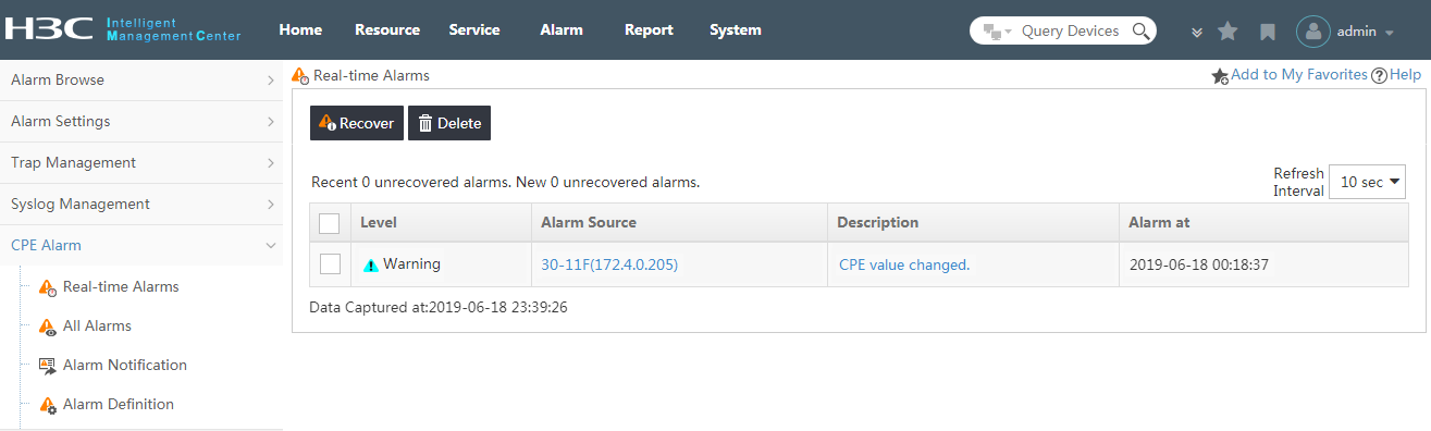
Viewing realtime alarms
The Real-time Alarms page displays:
· Refresh Interval—The alarms received within the latest refresh interval are new alarms. From the Refresh Interval list in the upper right corner of the browsing pane, you can set the refresh interval to 5 seconds, 10 seconds, 30 seconds, 1 minute, or 5 minutes. The default interval is 10 seconds.
· Level—The current severity or alarm level status for the associated alarm.
· Alarm Source—The CPE name, IP address, or both to which this alarm refers. This field contains an active link to navigate to the CPE details page for the source of this alarm. Locate and click the active link in this field to view the CPE Details page.
· Description—A description of the event or condition causing the alarm. The Description field contains a link to the alarm details for the selected alarm. Locate and click the active link in this field to view the Alarm Details page.
· Alarm at—The date and time stamp of this alarm.
|
|
NOTE: You can view alarms only for the CPEs to which you have management access and control. |
Recovering realtime alarms
Alarm recovery can be done by the system or by an operator. Operators can recover one or more alarms from the realtime alarms list. Recovering an alarm has the effect of clearing it from the Real-time Alarm view, while retaining it in the alarm database for a period of time. When an alarm is recovered, the selected alarm instance is considered resolved, and it is removed from notification functions. Recovered alarms can still be viewed from the All Alarms view.
To recover one or more alarms from the realtime alarms list:
1. Click Alarm > CPE Alarm > Real-time Alarms.
2. On the Real-time Alarms page, select the check boxes to the left of the alarm entries you want to recover. If you want to recover all the alarms at the same time, select the check box to the left of the Level tab.
3. Click Recover in the upper left corner of the Real-time Alarms list to recover all the selected alarms.
|
|
NOTE: · To recover alarms, you must be a system maintainer or an administrator, and you must have management access to and control of the CPEs that cause the alarms. · For each recovered alarm, the fault is cleared and no longer has any effect on the service. The system changes the alarm status to recovered upon receiving the CPE recovery message. · The system monitors unrecovered alarms every morning, and recovers those not recovered within 30 days. However, the system does not recover the alarms generated by inaccessible devices. |
Deleting realtime alarms
Deleting alarms removes alarm events from the database. BIMS is not able to report on an alarm when it has been deleted. Alarm histories are a valuable data source for performance management, and should be considered before deleting any alarm. Instead, you can recover an alarm. Recovering an alarm only clears it from the realtime alarm list while retaining it in the alarm database for a period of time.
|
|
NOTE: · After a CPE in the system is removed, the alarms related to the CPE are deleted. · To delete alarms, you must be a system maintainer or an administrator, and you must have management access to and control of the CPEs that cause the alarms. |
To delete one or more alarms from the realtime alarms list:
1. Click Alarm > CPE Alarm > Real-time Alarms.
2. On the Real-time Alarms page, select the check boxes to the left of the alarm entries that you want to delete. If you want to delete all the alarms at the same time, select the check box to the left of the Level tab.
3. Click Delete, in the upper left corner of the list, to delete all the selected alarms.
Managing all alarms
The All Alarms page lists alarms of all kinds, recovered, unrecovered, acknowledged, and unacknowledged. Using search capabilities from the All Alarms page, you can query the alarm database, which contains all the alarms that have not been deleted. You can recover, acknowledge, or delete these alarms.
To view the All Alarms page:
Click Alarm > CPE Alarm > All Alarms.
The All Alarms page appears, as shown in Figure 5.
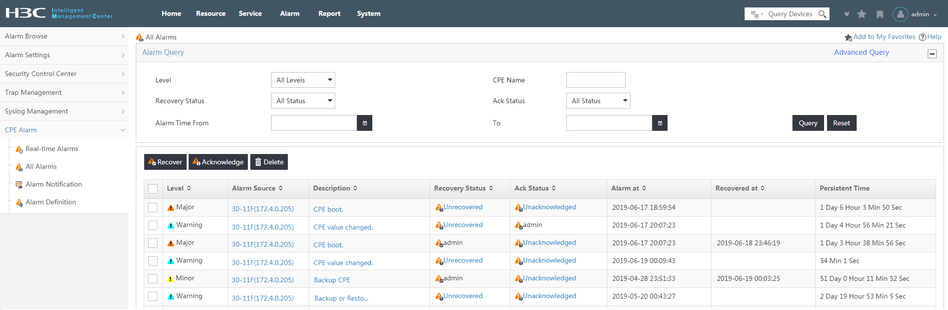
Viewing all alarms
On the All Alarms page, you can view the following information:
· Level—The current severity or alarm level status for the associated alarm.
· Alarm Source—The CPE name, IP address, or both, to which this alarm refers. Grayed-out CPE names or IP addresses indicate either that the alarm is generated by the IMC server or that the CPE is unmanaged. This field contains an active link to the CPE Details page for the source of this alarm. Locate and click the active link in this field to view the CPE Details page.
· Description—A description of the event or condition causing the alarm. The Description field contains a link. Locate and click this link to view the Alarm Details page. Click the More Events link on the Alarm Details page to show all alarms specific to the CPE specified to the left of Alarm Source. From the Alarm Details page, you can also delete or acknowledge the alarm, or edit the Maintenance Experience.
· Recovery Status—Whether the alarm is resolved or can be ignored. Click the active link in this field to change the Recovery Status of the selected alarm.
· Ack Status—Whether the alarm has been processed (acknowledged) by the system or the operator. Click the active link in this field to change the Ack Status of the selected alarm.
· Alarm at—The date and time stamp of this alarm.
· Recovered at—The date and time when the alarm was recovered.
· Persistent Time—The time span of an alarm.
|
|
NOTE: You can view alarms only for the CPEs to which you have management access and control. |
Querying alarms from the All Alarms page
Through the query function available on the
All Alarms page, you can search alarms that meet specified query criteria.
There are two alarm query methods available on the All Alarms page, the Basic Query and
the Advanced Query. The default alarm query is Basic Query. The two query methods
can be toggled by clicking the active link in the upper right corner of the Alarm Query box.
If the link to the right is Basic
Query, then you are in the Advanced Query
mode already. In either query mode, you can save a query criteria combination
by clicking Add to My Favorites in the upper right
corner of the All Alarm page. You can reuse this query criteria combination later by clicking
![]() to the left of the tabular navigation
system.
to the left of the tabular navigation
system.
Basic query
To query for alarms using Basic Query:
1. On the All Alarms page, change to Basic Query mode by clicking the link in the upper right corner of the Alarm Query pane.
2. Select the query criteria:
¡ Level—Query for a specific alarm or severity level. The default alarm level is All Levels. Select this option from the list.
¡ CPE Name—Enter a CPE name or IP address in the text box to view alarms that refer to the specified CPE.
¡ Recovery Status—Select alarms that have or have not been recovered by an operator or system. The default Recovery Status is All Status. Options include: All Status, Recovered and Unrecovered.
¡ Ack Status—Select alarms that have or have not been acknowledged by an operator. The default Ack Status is All Status. Options include: All Status, Acknowledged and Unacknowledged.
¡ Alarm Time From...To—Query for alarms
by time range. Click the Calendar icon ![]() to the right of
the From text box to select the start time. Click
the Calendar icon
to the right of
the From text box to select the start time. Click
the Calendar icon ![]() to the right of the To text box to
select the end time.
to the right of the To text box to
select the end time.
3. Click Query.
Alarms meeting the query criteria appear in the All Alarms list
4. Click Reset to restore the default query criteria, and display the alarms meeting the default query criteria.
Advanced query
To query for alarms using Advanced Query:
1. On the All Alarms page, change to Advanced Query mode by clicking the link in the upper right corner of the Alarm Query pane.
2. Select the query criteria:
¡ CPE—Select one or more CPEs for searching all alarms referring to them. You can directly enter the CPE name or IP address in the text box and then click Add. Or click Select CPE to open the Query CPE page, and select specific CPEs by searching.
¡ Level—Select the check boxes of alarm or severity levels.
¡ Alarm at—Query for alarms by time
range. Click the Calendar icon ![]() to the right of
the Start Time text box to select the start time.
Click the Calendar icon
to the right of
the Start Time text box to select the start time.
Click the Calendar icon ![]() to the right of
the End Time text box to select the end time.
to the right of
the End Time text box to select the end time.
¡ Ack Status—From the list, select alarms that have or have not been acknowledged by an operator. The default Ack Status is All Status. Options include: All Status, Acknowledged and Unacknowledged.
¡ Recovery Status—From the list, select alarms that have or have not been recovered by an operator or system. The default Recovery Status is All Status. Options include: All Status, Recovered and Unrecovered.
¡ Description—Enter a description for the alarms.
3. Click Query.
Alarms meeting the query criteria appear in the All Alarms list.
4. Click Reset to restore the default query criteria, and display the alarms meeting the default query criteria.
Recovering alarms from the All Alarms page
You can recover alarms from the All Alarms page.
When an alarm is recovered, the selected alarm instance is considered resolved
and removed from notification functions. Recovered alarms can still be viewed
from the All Alarms list. If an alarm is recovered by the system, the Recovery Status
field shows ![]() .
If an alarm is recovered by an administrator, the Recovery Status field shows
.
If an alarm is recovered by an administrator, the Recovery Status field shows ![]() . If an alarm
is recovered manually by an operator, the Recovery Status field shows
. If an alarm
is recovered manually by an operator, the Recovery Status field shows ![]() followed by
the operator's user name. This recovery operation is irreversible.
followed by
the operator's user name. This recovery operation is irreversible.
To recover one or more alarms, you can
either click ![]() in the Recovery Status
field or perform the following steps:
in the Recovery Status
field or perform the following steps:
1. Click Alarm > CPE Alarm > All Alarms.
2. On the All Alarms page, select the check boxes to the left of the alarm entries you want to recover. To recover all the alarms at the same time, select the check box to the left of the Level tab.
3. Click Recover in the upper left corner of the all alarms list to recover all the selected alarms.
The Recovery Status field changes from ![]() to
to ![]() , followed by the
operator's user name.
, followed by the
operator's user name.
Deleting alarms from the All Alarms page
Deleting alarms removes alarm events from the alarm database. BIMS is not able to report on an alarm when it has been deleted. Since alarm histories are a valuable data source for managing your network infrastructure, you should consider this before deleting an alarm. Rather than deleting, you can recover an alarm. Recovering an alarm clears it from alarm views, while retaining it in the alarm database for a period of time.
|
|
NOTE: · After a CPE in the system is removed, the alarms related to the CPE are deleted. · To delete alarms, you must be a system maintainer or an administrator, and you must have management access to and control of the CPEs that cause the alarms. |
To delete one or more alarms from the All Alarms list:
1. Click Alarm > CPE Alarm > All Alarms.
2. On the All Alarms page, select the check boxes to the left of the alarm entries that you want to delete. To delete all the alarms at the same time, select the check box to the left of the Level tab.
3. Click Delete in the upper left corner of the All Alarms list to delete all the selected alarms.
To delete an alarm from the Alarm Details page:
1. Click Alarm > CPE Alarm > All Alarms.
2. On the All Alarms page, locate and click the active link in the Description field to open the Alarm Details page.
3. On right side of the Alarm Details page, click Delete in the Action pane.
4. Click OK.
Acknowledging all alarms
The acknowledge status (Ack status) of an alarm indicates whether the alarm has been processed, either by the system or an operator.
|
|
NOTE: You can acknowledge alarms only for CPEs to which you have management access and control. |
To acknowledge one or more alarms from the All Alarms list:
1. Click Alarm > CPE Alarm > All Alarms.
2. On the All Alarms page, select the check boxes to the left of the alarm entries that you want to acknowledge. To acknowledge all the alarms at the same time, select the check box to the left of the Level tab.
3. Click Acknowledge in the upper left corner of the All Alarms list.
To acknowledge an alarm from the Alarm Details page:
1. Click Alarm > CPE Alarm > All Alarms.
2. On the All Alarms page, locate and click the active link in the Description field to open the Alarm Details page.
3. On right side of the Alarm Details page, click Acknowledge in the Action pane.
4. Click OK.
Editing maintenance experience
Use this function to edit the maintenance experience of an alarm to facilitate troubleshooting.
To edit the maintenance experience of an alarm:
1. Click Alarm > CPE Alarm > All Alarms.
2. On the All Alarms page, locate and click the active link in the Description field.
The Alarm Details page for the selected alarm appears.
On right side of the Alarm Details page, click Edit Maintenance Experience in the Action pane.
1. In the dialog box, complete the maintenance experience edits.
2. Click OK to submit the maintenance experience and refresh the Alarm Details page.
Managing alarms notification
When alarms conform to one or more alarm notification rules, the alarm notification function is triggered to send notifications for those alarms to the designated recipients in three possible ways: mail notification, message notification, and alarm forwarding. From the Alarm Notification page, you can define the alarm notification rules and how notifications are sent.
To view the Alarm Notification page:
Click Alarm > CPE > Alarm Notification.
The Alarm Notification page appears.
From this page, you can view the three main notification methods:
· Mail Notification
· Message Notification
· Alarm Forwarding
From this page, you can access the following information for each notification rule:
· Rule Name—The name of the notification rule.
· Status—The status (enabled or disabled) of a notification rule.
· Destination Mail Address—The mail address of the designated recipients.
· Phone Number—The phone number of the designated recipients.
· Destination Address/Port—The IP address and port information of the target server.
From this page, you can:
· Enable or disable a notification rule.
· Navigate to the page for configuring the mail server.
· Navigate to the page for configuring the Short Message Service Center (SMSC) server.
· Navigate to the page for adding or modifying a notification rule.
· Delete a notification rule.
· Navigate to the page for copying a notification rule.
· Refresh the alarm notification rules.
Managing mail notifications
The mail notification function enables the system to inform the operator of an alarm by e-mail.
Configuring the mail server
A mail server must be configured to enable the system to send alarm notifications by email.
|
|
NOTE: The mail authentication configuration of the system must be consistent with that of the server. If you have enabled authentication on the server for sending an email, you must also enable it on the mail server in the system. If not, you will not have authentication options on the mail server. |
To configure the mail server:
1. Click Alarm > CPE Alarm > Alarm Notification.
2. On the Alarm Notification page, click Configure Mail Server in the upper right corner of the page.
3. On the Configure Mail Server page, enter the Server Address.
4. Select whether to require a security connection (SSL).
5. Select whether to enable authentication. If yes, enter the Username and Password of the sender's mailbox.
6. Enter the sender's email address.
7. Click Test Mailbox to test if you can connect to the mail server. If you cannot connect, confirm that the configuration settings you entered are correct, and modify as needed until you can connect.
8. Click OK.
Adding or modifying a mail notification rule
On the Alarm Notification page, you can add one or more new notification rules, or modify existing ones.
|
|
NOTE: The mail alarm notification only takes effect after the mail server is properly configured. |
To add or modify a mail notification rule:
1. Click Alarm > CPE Alarm > Alarm Notification.
2. In the Mail Notification pane on the Alarm Notification page, do one of the following:
¡ To add a new rule, click Add to open the Add Mail Notification page, and then proceed with step 3.
¡ To
modify a rule, click its Modify icon ![]() to open the page for modifying the rule, and then proceed with step
4.
to open the page for modifying the rule, and then proceed with step
4.
3. Enter a Rule Name for the notification rule.
|
|
NOTE: This step is mandatory for adding a mail notification rule. After you create a rule, you cannot modify its name. |
4. Set one or more conditions for the notification rule. The logical relation among conditions is AND.
¡ Destination Mail Address—Enter a recipient's email address. To add a new mail address, enter it in this field, and then click Add. To remove a mail address from the address list, select it by left-clicking it in the list, and then click Delete.
¡ Concerned Alarm Levels—Set your required alarm severity levels by selecting the check boxes of the corresponding alarm levels.
¡ Concerned CPEs—Do one of the following:
- Select All CPEs to forward alarms for all CPEs.
- Select Selected CPEs to specify CPEs for forwarding. Then click Select CPE to the right of the new CPE list that appears, and select the CPEs on the resulting CPE Query popup.
You can remove unwanted CPEs from this list by selecting the CPE, and then clicking Delete CPE.
Only the alarms from the selected CPEs are forwarded.
¡ Concerned Alarms—Do one of the following:
- Select All Alarms to forward all types of alarms.
- Select Selected Alarms to specify types of alarms for forwarding. Then click Select Alarm to the right of the new alarms list that appears, select the alarms on the resulting Select Alarm popup.
You can remove unwanted alarms from the list by selecting the alarm, and then clicking Delete.
Only the selected alarms are forwarded.
¡ Time Range Configuration—Enter the time range on each day in the format of hh:mm-hh:mm. The system forwards only the alarms generated within the time ranges you specify. For example, if you type 00:00–24:00 in the text box to the right of Monday, all alarms generated on Monday are forwarded.
5. Click OK to confirm the configuration and save the notification rule.
Enabling or disabling a mail notification rule
If the Status of a notification rule is Enabled, it means this rule is active. If the Status of a notification rule is Disabled, it means this rule is inactive.
To enable or disable a mail alarm notification rule:
1. Click Alarm > CPE Alarm > Alarm Notification.
2. In the Mail Notification pane on the Alarm Notification page, locate and click the link in the Status field to enable or disable a mail notification rule.
Copying a mail notification rule
Use this function to quickly add a new mail notification rule by copying an existing rule.
To copy a mail notification rule:
1. Click Alarm > CPE Alarm > Alarm Notification.
2. On the Alarm
Notification page, click the Copy icon ![]() in the mail notification list associated with the notification rule
you want to copy.
in the mail notification list associated with the notification rule
you want to copy.
3. On the Copy Mail Notification page, rename the rule using a unique name.
4. Make any necessary modifications to the rule.
5. Click OK.
Deleting a mail notification rule
To delete a mail notification rule:
1. Click Alarm > CPE Alarm > Alarm Notification.
2. On the Alarm
Notification page, click the Delete icon ![]() in the Mail Notification list
associated with the notification rule you want to delete.
in the Mail Notification list
associated with the notification rule you want to delete.
3. Click OK.
Managing message notifications
The message notification function enables the system to inform the maintainer of alarms by sending text messages to devices configured to receive them.
|
|
NOTE: A short message modem must be installed in the IMC server before you can use this function. |
Configuring the SMSC server
An SMSC server must be configured to enable the system to send alarm notifications using short messages.
To configure the SMSC server:
1. Click Alarm > CPE Alarm > Alarm Notification.
2. On the Alarm Notification page, click Configure SMSC in the upper right corner of in the message notification pane. The page updates to display all SMSCs.
3. Click Add.
4. Enter an SMSC name in the SMSC Name field.
5. Select the serial port connecting the message sending device to the SMSC server from the Connect Using list.
6. Select the Baud rate.
7. Enter the Country Code.
8. Enter the SMSC Number.
9. Click OK.
Adding or modifying a message notification rule
On the Alarm Notification page, you can add one or more new notification rules, or modify existing ones.
|
|
NOTE: The message alarm notification takes effect only after the SMSC server is properly configured. |
To add or modify a message notification rule:
1. Click Alarm > CPE Alarm > Alarm Notification.
2. In the Message Notification pane on the Alarm Notification page, do one of the following:
¡ To add a new rule, click Add to open the Add Message Notification page, and then proceed with step 3.
¡ To
modify a rule, click its Modify icon ![]() to open the page for modifying the rule, and then proceed with step
4.
to open the page for modifying the rule, and then proceed with step
4.
3. Enter a Rule Name for the notification rule.
|
|
NOTE: This step is mandatory for adding a message notification rule. After you create a rule, you cannot modify its name. |
4. Set one or more conditions for the notification rule. The logical relation among conditions is AND.
¡ Telephone Number—Enter a recipient's telephone number. To add a new telephone number, enter it in this field, and then click Add. To remove a telephone number, select it by left-clicking it in the list, and then click Delete.
¡ Concerned Alarm Levels—Set your required alarm severity levels by selecting the check boxes of the corresponding alarm levels.
¡ Concerned CPEs—Do one of the following:
- Select All CPEs to forward alarms for all CPEs.
- Select Selected CPEs to specify CPEs for forwarding. Then click Select CPE to the right of the new CPE list that appears, and select the CPEs on the resulting CPE Query popup.
You can remove unwanted CPEs from this list by selecting the CPE, and then clicking Delete CPE.
Only the alarms from the selected CPEs are forwarded.
¡ Concerned Alarms—Do one of the following:
- Select All Alarms to forward all types of alarms.
- Select Selected Alarms to specify types of alarms for forwarding. Then click Select Alarm to the right of the new alarms list that appears, select the alarms on the resulting Select Alarm popup.
You can remove unwanted alarms from the list by selecting the alarm, and then clicking Delete.
Only the selected alarms are forwarded.
¡ Time Range Configuration—Enter the time range on each day in the format of hh:mm-hh:mm. The system forwards only the alarms generated within the time ranges you specify. For example, if you type 00:00–24:00 in the text box to the right of Monday, all alarms generated on Monday are forwarded.
5. Click OK to confirm the configuration and save the notification rule.
Enabling or disabling a message notification rule
If the Status of a notification rule displays Enabled, it means this rule is active. If the Status of a notification rule displays Disabled, it means this rule is inactive.
To enable or disable a message alarm notification rule:
1. Click Alarm > CPE Alarm > Alarm Notification.
2. In the Message Notification pane on the Alarm Notification page, locate and click the link in the Status field to enable or disable a message notification rule.
Copying a message notification rule
Use this function to quickly add a new message notification rule by copying an existing notification rule.
To copy a message notification rule:
1. Click Alarm > CPE Alarm > Alarm Notification.
2. On the Alarm
Notification page, click the Copy icon ![]() in the Message Notification list
associated with the notification rule you want to copy.
in the Message Notification list
associated with the notification rule you want to copy.
3. On the Copy Message Notification page, rename the rule using a unique name.
4. Make any necessary modifications to the rule.
5. Click OK.
Deleting a message notification rule
To delete a message notification rule:
1. Click Alarm > CPE Alarm > Alarm Notification.
2. On the Alarm
Notification page, click the Delete icon![]() in the Message Notification list
associated with the notification rule you want to delete.
in the Message Notification list
associated with the notification rule you want to delete.
3. Click OK.
Managing alarm forwarding
The system sends alarm information in the Syslog format to the specified third-party server according to the configured alarm forwarding rule.
Adding or modifying an alarm forwarding rule
On the Alarm Notification page, you can add one or more new notification rules, or modify existing ones.
To add or modify an alarm forwarding rule:
1. Click Alarm > CPE Alarm > Alarm Notification.
2. In the Alarm Forwarding pane on the Alarm Notification page, do one of the following:
¡ To add a new rule, click Add to open the Add Alarm Forwarding page, and then proceed with step 3.
¡ To
modify a rule, click its Modify icon ![]() to open the page for modifying the rule, and then proceed with step
4.
to open the page for modifying the rule, and then proceed with step
4.
3. Enter a Rule Name for the notification rule.
|
|
NOTE: This step is mandatory for adding an alarm forwarding rule. After you create a rule, you cannot modify its name. |
4. Set one or more conditions for the notification rule. The logical relation among conditions is AND.
¡ Destination IP Address—Enter the IP address of the destination management system.
¡ Port—Specify the port of the destination management system.
¡ Concerned Alarm Levels—Set your required alarm severity levels by selecting the check boxes of the corresponding alarm levels.
¡ Concerned CPEs—Do one of the following:
- Select All CPEs to forward alarms for all CPEs.
- Select Selected CPEs to specify CPEs for forwarding. Then click Select CPE to the right of the new CPE list that appears, and select the CPEs on the resulting CPE Query popup.
You can remove unwanted CPEs from this list by selecting the CPE, and then clicking Delete CPE.
Only the alarms from the selected CPEs are forwarded.
¡ Concerned Alarms—Do one of the following:
- Select All Alarms to forward all types of alarms.
- Select Selected Alarms to specify types of alarms for forwarding. Then click Select Alarm to the right of the new alarms list that appears, select the alarms on the resulting Select Alarm popup.
You can remove unwanted alarms from the list by selecting the alarm, and then clicking Delete.
Only the selected alarms are forwarded.
¡ Time Range Configuration—Enter the time range on each day in the format of hh:mm-hh:mm. The system forwards only the alarms generated within the time ranges you specify. For example, if you type 00:00–24:00 in the text box to the right of Monday, all alarms generated on Monday are forwarded.
5. Click OK to confirm the configuration and save the alarm forwarding rule.
Enabling or disabling an alarm forwarding rule
If the Status of an alarm forwarding rule displays Enabled, it means this rule is active. If the Status of an alarm forwarding rule displays Disabled, it means this rule is inactive.
To enable or disable an alarm forwarding rule:
1. Click Alarm > CPE Alarm > Alarm Notification.
2. In the Alarm Forwarding pane on the Alarm Notification page, locate and click the link in the Status field to enable or disable an alarm forwarding rule.
Copying an alarm forwarding rule
Use this function to quickly add a new alarm forwarding rule by copying an existing alarm forwarding rule.
To copy an alarm forwarding rule:
1. Click Alarm > CPE Alarm > Alarm Notification.
2. On the Alarm
Notification page, click the Copy icon ![]() associated with the alarm forwarding rule you want to copy.
associated with the alarm forwarding rule you want to copy.
3. On the Copy Alarm Forwarding page, rename the rule using a unique name.
4. Make any necessary modifications to the rule.
5. Click OK.
Deleting an alarm forwarding rule
1. Click Alarm > CPE Alarm > Alarm Notification.
2. On the Alarm
Notification page, click the Delete icon ![]() in the rule list associated with the alarm forwarding rule you want
to delete.
in the rule list associated with the alarm forwarding rule you want
to delete.
3. Click OK.
Managing alarm definitions
BIMS uses system and user-defined rules to determine which of the events received by BIMS should be considered alarms. Upon installation, alarms can be generated from those events that conform to system-defined rules. Alarms can also be generated from those events matching the rules that are defined by administrators. You can create rules from scratch or you can modify an existing system-defined rule to meet your requirements. The following section explores the use of the Alarm Definition page.
To view the Alarm Definition page:
1. Click the Alarm > CPE Alarm > Alarm Definition.
The Alarm Definition page appears, as shown in Figure 6.
Figure 6 Alarm Definition page
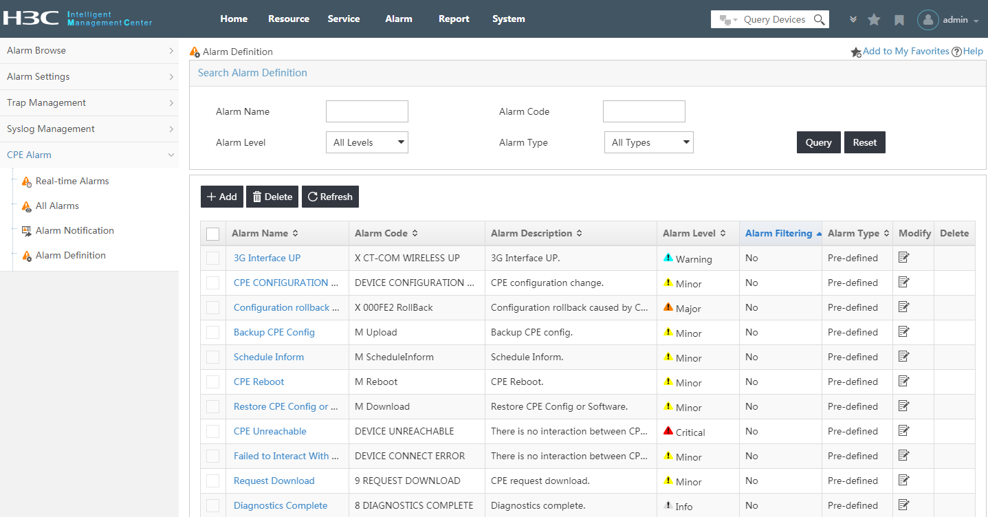
Viewing alarm definitions
On the Alarm Definition page, you can view the following information:
· Alarm Name—The alarm name.
· Alarm Code—The unique identification of an alarm definition.
· Alarm Description—A description of the event or condition that causes the alarm.
· Alarm Level—The current severity or alarm level status for the associated alarm definition. The value can be Critical, Major, Minor, Warning, or Info.
· Alarm Filtering—The alarm filter status, Yes or No. When Yes is selected, BIMS ignores the alarms that match the alarm definition. When No is selected, BIMS records and processes the alarms that match the alarm definition.
· Alarm Type—Whether the alarm type is Predefined or Vendor defined.
Querying alarm definitions
Using the query function available on the Alarm Definition page, you can search alarm definitions that meet specified query criteria.
To query for alarm definitions:
1. Click Alarm > CPE Alarm > Alarm Definition.
2. In the Search Alarm Definition pane on the Alarm Definition page, select the query criteria:
¡ Alarm Name—The alarm name.
¡ Alarm Code—The unique identification of an alarm definition.
¡ Alarm Level—The current severity or alarm level status for the associated alarm. Options include: Critical, Major, Minor, Warning, Info, and All Levels (the default).
¡ Alarm Type—The alarm type. Options include: All Types (the default), Predefined and Vendor defined.
3. Click Query.
The alarm definitions meeting the query criteria appear in the alarm definition list.
4. Click Reset to restore the default query criteria.
Adding or modifying alarm definitions
To add or modify alarm definitions:
1. Click Alarm > CPE Alarm > Alarm Definition.
2. In the Alarm Definition List pane on the Alarm Definition page, do one of the following:
¡ To add a new definition, click Add to open the Add Alarm Definition page, and then proceed with step 3.
¡ To
modify a definition, click its Modify icon ![]() to open the page for modifying the definition, and then proceed
with step 5.
to open the page for modifying the definition, and then proceed
with step 5.
3. Enter an Alarm Name.
|
|
NOTE: This step is mandatory for adding an alarm definition. After you create a definition, you cannot modify its name. |
4. Enter a unique Alarm Code Click the question mark symbol on the right side to display help about the Alarm Code format. For the correct alarm code, consult the equipment supplier for the private alarm code, or refer to the RFC for the public alarm code.
5. Set one or more conditions for the alarm definition. The logical relation among conditions is AND.
¡ Alarm Level—Select Critical, Major, Minor, Warning, or Info.
¡ Alarm Filtering—Select:
- Yes for BIMS to ignore the alarms matching the alarm definition.
- No for BIMS to record and process alarms matching the alarm definition.
¡ Alarm Description—Enter a string to describe this alarm definition. The description must match some or all of the content in the Syslog event description field, for this definition to generate an alarm in BIMS.
¡ Syslog Descriptor—Enter a Syslog descriptor to define this alarm. This is a key word to identify a Syslog message.
¡ Syslog Description—Enter a Syslog description to define this alarm. This is the details of a Syslog message.
¡ Alarm Cause—Enter the cause of the alarm.
¡ Remediation Suggestion—Enter the method that can be used to fix the alarm.
¡ Maintenance Experience—Enter the maintenance experience to facilitate troubleshooting.
6. Click OK to confirm the configuration and save the alarm definition.
Deleting alarm definitions
System predefined alarm definitions cannot be deleted. However, user-defined alarm definitions can be deleted.
To delete an alarm definition:
1. Click Alarm > CPE Alarm > Alarm Definition.
2. On the Alarm Definition page, click the Delete icon![]() in the alarm
definition entry that you want to delete.
in the alarm
definition entry that you want to delete.
3. Click OK.
|
|
NOTE: The Delete icon |
Mobile branch management
Overview
The Mobile Branch Management (MBM) component is developed by H3C on the basis of the IMC Platform and BIMS. With ease of deployment and management, and high security, MBM provides an efficient and cost-effective solution to centrally manage mobile branch networks. Mobile branch networks can back up the wired networks between headquarters and branches to provide high availability. MBM manages all devices that connect to ISP networks through SIM cards. You can enable automated teller machines (ATMs) to access networks by connecting them to mobile branch devices. Such ATMs are typically located in shopping malls, office buildings, and remote areas where fixed networks are not deployed. HP and H3C MSR routers can connect to an ISP network through SIM cards in one of the following ways:
· 3G modem—An MSR router connects to a 3G modem through the USB port or the SIC card slot. Make sure the 3G SIM card is inserted into the 3G modem.
· Devices with built-in SIM card slots—An MSR router has one or more built-in SIM card slots. Make sure the 3G SIM card is inserted into the built-in SIM card slot.
Support for the access methods varies by device models. For more information, see the configuration guides of the MSR router series.
With MBM and BIMS, you can manage mobile branch devices by using the following procedures:
1. Add devices to MBM and deploy SMS to the devices. The devices go online in MBM and BIMS when they are powered on.
2. Deploy configuration and software to devices. After the devices come online in MBM and BIMS, you can perform configuration and software deployment on the devices from BIMS.
3. Manage mobile branch devices in groups:
a. Add the devices to different location views and service provider views, based on their physical locations and the service providers of their phone numbers.
b. Locate the devices on the GIS map according to the base station location information of their SIM cards.
c. Display the performance information and SIM card statistics in graphs, including traffic, signal strength, and online duration information.
MBM provides the following functions:
· Mobile device management—Provides centralized management for mobile branch devices. It includes the following functions:
¡ Device management—Manages the devices centrally. You can add, modify, delete, import, or export mobile branch devices.
¡ SMS deployment—Deploys SMS to the devices. The devices go online in MBM and BIMS when they are powered on.
¡ User management—Works with UAM to manage SIM card users.
· View management—Provides view management for mobile branch devices. It includes the following functions:
¡ Location View Management—Manages devices in groups according to their physical locations.
¡ Service Provider View Management—Manages devices in groups according to the service providers to which their phone numbers belong.
· GIS Map—Displays devices based on the base station location information of their SIM cards. This function also allows you to view basic device information, change the device update status, and move devices on the map.
· Mobile Branch Topology—Enables you to view the topology of the location views to which all mobile branch devices belong.
· Configuration Management—Stores system-defined and user-defined configuration templates and software, and allows you to view the basic configuration and software information, and deploy configuration and software to devices. This function references the Configuration Management function of BIMS.
· Performance Management—Monitors performance information for SIM cards, including the online duration, traffic, and signal strength, and displays information on the MBM homepage in graphs.
· Option Management—Allows you to configure SMS gateways, BIMS default settings, lock mobile areas, and UAM server parameters to make sure MBM operates correctly.
· MBM Report—Provides performance statistics reports for the SIM cards and devices, to inform you of SIM card usage for the devices on mobile branch networks.
MBM homepage
The MBM homepage displays the overall SIM card performance in graphs for the mobile branch devices. The graphs include the Traffic Statistics Trend Graph-Today, Location View, Top5 Worst SIM Card Signal Strength-Today, Top5 Traffic of Devices-This Month, and Top5 SIM Card Offline Duration-This Month graphs.
To access the MBM homepage:
1. Click the Service tab.
2. From the navigation tree, select MBM > Homepage.
Traffic Statistics Trend Graph-Today
As shown in Figure 7, the line chart displays traffic statistics of the mobile branch devices from 00:00 to the current time, including received traffic and sent traffic.
Figure 7 Traffic Statistics Trend Graph-Today
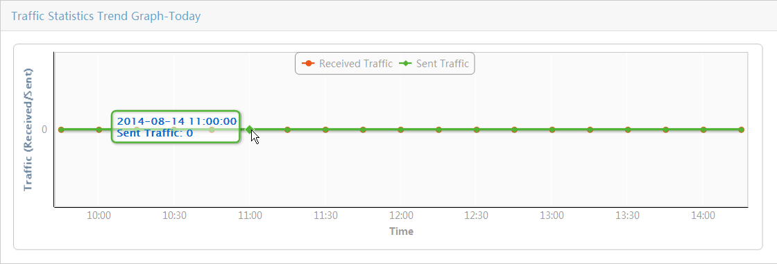
Location View
As shown in Figure 8, the pie chart displays the distribution of the mobile branch devices in different locations.
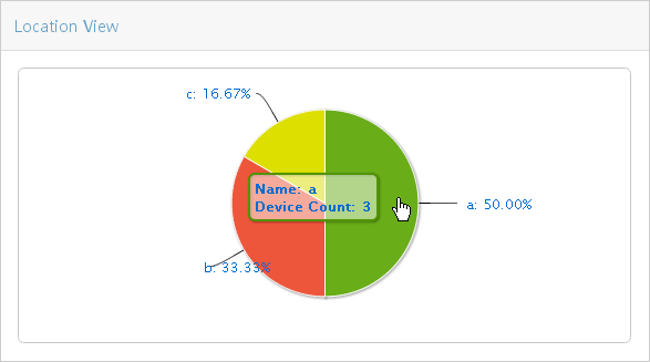
Place the cursor over a colored area to view the number of devices for a specific location. Click a colored area to view the list of subviews and devices for that location view. The Others slice does not serve as a link to any view list page. Based on the number of location views, the Others slice might represent the following:
· If the total number of location views is less than 9, the Others slice represents the number of devices that do not belong to any location views.
· If the total number of location views is equal to or greater than 9, the Others slice represents the number of devices that do not belong to the location views displayed on the pie chart.
Top5 Worst SIM Card Signal Strength-Today
As shown in Figure 9, the bar chart displays the top 5 SIM cards with the worst average signal strength from 00:00 to the current time.
Figure 9 Top5 Worst SIM Card Signal Strength-Today
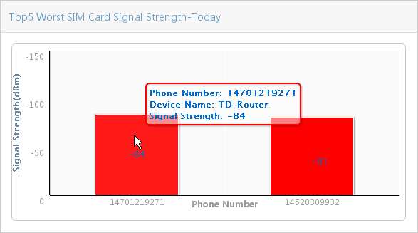
Top5 Traffic of Devices-This Month
As shown in Figure 10, the bar chart displays the top 5 devices with the most traffic received and sent this month.
Figure 10 Top5 Traffic of Devices-This Month
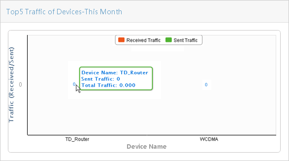
Top5 SIM Card Offline Duration-This Month
As shown in Figure 11, the bar chart displays the top 5 SIM cards with the longest offline duration this month.
Figure 11 Top5 SIM Card Offline Duration-This Month
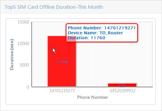
Configuration guidelines
When you use MBM for the first time, perform the following tasks:
1. Configure global parameters, including the SMS gateway, BIMS parameters, and UAM server parameters (if necessary). Make sure the service providers have been added to the service provider views. For more information, see "Configuring MBM options."
2. Add device information to MBM. MBM automatically synchronizes the device information to the BIMS component. They are considered as virtual devices because they have not connected to MBM and BIMS. As a best practice, select Automatically Add to IMC when you add device information to MBM. The IMC Platform can provide more comprehensive management functions. For more information, see "Adding a mobile branch device".
3. Deploy the configuration. Create the automatic configuration deployment and bind the configuration files to the virtual devices. You can configure the configuration files as needed, such as VPN configuration and DHCP parameters. For more information, see "Automatically deploying mobile branch device configurations."
4. Deploy SMS. For more information, see "SMS deployment."
The SMS deployment procedure is as follows:
a. MBM uses the SMS gateway to send zero configuration files to devices as messages. The zero configuration files include the BIMS parameters and SIM card parameters.
b. A device receives a configuration message and establishes a connection to the BIMS server. The device then comes online in MBM and BIMS.
c. After the device goes online in BIMS, it automatically obtains and deploys configuration files bound to the corresponding virtual devices. For example, when the VPN configuration is deployed, a VPN tunnel is established between the device and the IMC Platform. From the VPN tunnel, IMC can obtain the location information, real-time performance data, and performance statistics of the device.
After the configuration is complete, you can manage the mobile branch devices in MBM and view the performance monitoring information for SIM cards. For more information, see "Performance management."
Mobile branch device management
Mobile branch devices operate with SIM cards, and provide services through a service provider. You can add mobile branch devices to MBM for centralized management by using the following functions:
· Device management—Adds device information to MBM for management.
· SMS deployment—Brings devices online in MBM and BIMS. The device status is then changed from Unknown to Normal. If an alarm occurs, the device status depends on the alarm level.
· User management—Manages SIM card users. This function requires cooperation with UAM.
Device management
Device management allows you to view mobile branch devices, manually add device information, or import device information through a file. You can perform SMS deployment after adding the device information to MBM.
Viewing the mobile branch device list
1. Click the Service tab.
2. From the navigation tree, select MBM > Resource Management > Device.
The Device List page displays all mobile branch devices.
Device List contents
¡ Status—Status of the mobile branch device, which is Unknown for an offline device, or Normal for an online device. If the device has alarms that have not been recovered or cleared, the status is determined by the highest severity or alarm level for the device.
¡ Device Name—Mobile branch device name. Click the name of a mobile branch device to view its details. For more information, see "Viewing detailed information about a mobile branch device."
¡ Serial Number—Serial number of the mobile branch device.
¡ Primary Phone Number—Phone number of the primary SIM card on the mobile branch device.
¡ Primary Username—User name of the primary SIM card on the mobile branch device.
¡ Primary Service Provider—Service provider to which the primary SIM card on the mobile branch device belongs.
¡ Operation—Click the Operation icon ![]() for the mobile branch device to display the operation menu.
for the mobile branch device to display the operation menu.
3. Click Column in the upper right corner of the device list to customize the column labels for the device list.
The Status, Device Name, and Serial Number labels cannot be customized. Select or clear the boxes of the label names in the Column window to display only the selected labels in the device list.
Besides the options previously described, the Column window provides the following options:
¡ Status in BIMS—Status of the mobile branch device in BIMS, which is Unknown for an offline device, or Normal for an online device. If the device has alarms that have not been recovered or cleared, the status is determined by the highest severity or alarm level for the device.
¡ Secondary Phone Number—Phone number of the secondary SIM card on the mobile branch device.
¡ Secondary Username—User name of the secondary SIM card on the mobile branch device.
¡ Secondary Service Provider—Service provider to which the secondary SIM card on the mobile branch device belongs.
¡ Location View—Location view to which the mobile branch device belongs.
¡ Send Trap—Indicates whether or not to send traps to IMC when the device receives an SMS message.
4. Click OK.
Querying mobile branch devices
1. Click the Service tab.
2. From the navigation tree, select MBM > Resource Management > Device.
The Device List page displays all mobile branch devices.
3. Enter a device name in the field in the
upper right corner of the Device List page, and
click the search icon ![]() , or click the Advanced icon
, or click the Advanced icon ![]() located in the
upper right corner of the page.
located in the
upper right corner of the page.
Enter or select one or more of the following query criteria:
¡ Status—Select a status of the mobile branch device. Options include Unlimited, Unmanaged, Unknown, Normal, Warning, Minor, Major, and Critical.
¡ Status in BIMS—Status of the mobile branch device in BIMS. Options include Unlimited, Unmanaged, Unknown, Normal, Warning, Minor, Major, and Critical.
¡ Device Name—Name of the mobile branch device. MBM supports fuzzy matching for this field. For example, if you enter A, all mobile branch devices with names containing A are queried.
¡ Serial Number—Serial number of the mobile branch device. MBM supports fuzzy matching for this field. For example, if you enter 1, all mobile branch devices with serial numbers containing 1 are queried.
¡ Phone Number—Phone number of the mobile branch device. MBM supports fuzzy matching for this field. For example, if you enter 2, all mobile branch devices with primary or secondary phone numbers containing 2 are queried.
¡ Location View—Location view name of the mobile branch device. MBM supports fuzzy matching for this field. For example, if you enter test, all mobile branch devices with location view names containing test are queried.
An empty field or a field that is set to Unlimited does not serve as a query criterion.
4. Click Query to display all mobile branch devices matching the query criteria.
5. Click Reset to clear the query criteria and display all mobile branch devices.
Viewing detailed information about a mobile branch device
1. Click the Service tab.
2. From the navigation tree, select MBM > Resource Management > Device.
The Device List page displays all mobile branch devices.
3. Click the name of the target mobile branch device.
The device details page appears.
Basic Information
¡ Device Name—Name of the mobile branch device.
¡ Device Description—Description of the mobile branch device.
¡ OUI—Vendor OUI of the mobile branch device.
¡ Serial Number—Serial number of the mobile branch device. An OUI and a serial number together identify a device.
SIM Card Information
¡ Primary Phone Number—Phone number of the primary SIM card on the mobile branch device.
¡ Primary IMSI Number—IMSI number of the primary SIM card on the mobile branch device.
¡ Service Provider—Service provider to which the primary SIM card on the mobile branch device belongs.
¡ Authentication Method—Authentication method used by the primary SIM card on the mobile branch device. Options include PAP, CHAP, and PAP+CHAP.
¡ Primary Username—User name of the primary SIM card on the mobile branch device.
¡ Primary Password—Password of the primary SIM card on the mobile branch device.
¡ Secondary Phone Number—Phone number of the secondary SIM card on the mobile branch device.
¡ Secondary IMSI Number—IMSI number the secondary SIM card on the mobile branch device.
¡ Service Provider—Service provider to which the secondary SIM card on the mobile branch device belongs.
¡ Authentication Method—Authentication method used by the secondary SIM card on the mobile branch device. Options include PAP, CHAP, and PAP+CHAP.
¡ Secondary Username—User name of the secondary SIM card on the mobile branch device.
¡ Secondary Password—Password of the secondary SIM card on the mobile branch device.
Automatically Add to IMC
¡ Automatically Add to IMC—Indicates whether or not to automatically add the device to IMC.
¡ Use Loopback Address as Management IP Address—Indicates whether or not to use the loopback address as the management IP address. This option is displayed only when the Automatically Add to IMC option is Yes.
¡ IP Address—Management IP address of the mobile branch device. This option is displayed only when the Use Loopback Address as Management IP Address option is No.
4. Click Close or the ![]() icon in
the upper right corner.
icon in
the upper right corner.
Adding a mobile branch device
1. Click the Service tab.
2. From the navigation tree, select MBM > Resource Management > Device.
The Device List page displays all mobile branch devices.
3. Click Add.
4. Set the following parameters:
Basic Information
¡ Device Name—Name of the mobile branch device.
¡ Device Description—Description of the mobile branch device.
¡ OUI—Vendor OUI of the mobile branch device.
¡ Serial Number—Serial number of the mobile branch device.
SIM Card Information
¡ Primary Phone Number—Phone number of the primary SIM card on the mobile branch device.
¡ Primary IMSI Number—Primary IMSI number of the mobile branch device.
¡ Service Provider—Service provider to which the primary SIM card on the mobile branch device belongs. Options are None and the available service provider names in Service Provider View Management.
¡ Authentication Method—Authentication method used by the primary SIM card on the mobile branch device. Options include PAP, CHAP, and PAP+CHAP.
¡ Primary Username—User name of the primary SIM card on the mobile branch device.
¡ Primary Password—Password of the primary SIM card on the mobile branch device.
|
|
NOTE: Each device can have a primary SIM card and a secondary SIM card. You must set all parameters for the primary SIM card. For the secondary SIM card, set either all of the parameters or none of the parameters. |
¡ Secondary Phone Number—Phone number of the secondary SIM card on the mobile branch device.
¡ Secondary IMSI Number—Secondary IMSI number of the mobile branch device.
¡ Service Provider—Service provider to which the secondary SIM card on the mobile branch device belongs. Options are None and the available service provider names in Service Provider View Management.
¡ Authentication Method—Authentication method used by the secondary SIM card on the mobile branch device. Options include PAP, CHAP, and PAP+CHAP.
¡ Secondary Username—User name of the secondary SIM card on the mobile branch device.
¡ Secondary Password—Password of the secondary SIM card on the mobile branch device.
Automatically Add to IMC
¡ Automatically Add to IMC—Specifies whether or not to automatically add the device to IMC. You can view the performance and statistics of a mobile branch device, and locate the device on the map, only after it is added to IMC.
¡ Use Loopback Address as Management IP Address—Specifies whether or not to use the loopback address as the management IP address. This option is displayed only when the Automatically Add to IMC option is selected.
¡ IP Address—Management IP address of the mobile branch device. This option is displayed only when the Use Loopback Address as Management IP Address option is not selected.
5. Click OK.
The operation result appears at the top of the page.
Synchronizing a mobile branch device
2. From the navigation tree, select MBM > Resource Management > Device.
The Device List page displays all mobile branch devices.
3. Click the Operation
icon ![]() for the target device, and select Synchronize from the popup menu. This
operation applies only to devices that are already added to IMC.
for the target device, and select Synchronize from the popup menu. This
operation applies only to devices that are already added to IMC.
The system reads information from the device, and updates the device information in MBM immediately.
Modifying a mobile branch device
1. Click the Service tab.
2. From the navigation tree, select MBM > Resource Management > Device.
The Device List page displays all mobile branch devices.
3. Click the Operation
icon ![]() for the target device, and select
for the target device, and select ![]() Modify
device from the popup menu.
Modify
device from the popup menu.
4. Modify the parameters.
OUI and Serial Number cannot be modified. For more information about the parameters, see "Adding a mobile branch device."
5. Click OK.
Deleting mobile branch devices
1. Click the Service tab.
2. From the navigation tree, select MBM > Resource Management > Device.
The Device List page displays all mobile branch devices.
3. Delete mobile branch devices by using one of the following methods:
¡ To
delete a single device, click the Operation icon ![]() for the target device, and select
for the target device, and select ![]() Delete device from the
popup menu.
Delete device from the
popup menu.
¡ To delete multiple devices, select the boxes to the left of the target devices, and click Delete at the top of the device list.
4. Click OK.
Importing mobile branch devices
This function allows you to import devices to MBM through a .csv file.
To import devices through a .csv file:
1. Click the Service tab.
2. From the navigation tree, select MBM > Resource Management > Device.
The Device List page displays all mobile branch devices.
3. Click Import and select Import Device from File.
Click Browse to select the target file, or enter the directory of the file in the Select File field. The file must be in CSV format. The first line in the file are column labels, and the rest are relevant contents.
Table 2 Import file column definitions
|
Column label |
Column contents/requirements |
|
Device Name |
Name of the mobile branch device. |
|
OUI |
Vendor OUI of the mobile branch device. |
|
Serial Number |
Serial number of the mobile branch device. |
|
Automatically Add to IMC |
Indicates whether or not to automatically add the device to IMC. · 0—No · 1—Yes You can view the performance and statistics of a mobile branch device, and locate the device on the map, only after it is added to IMC. |
|
Use Loopback Address as Management IP Address |
Indicates whether or not to use the loopback address as the management IP address. · 0—No · 1—Yes This parameter is valid only when the Automatically Add to IMC value is set to 1. |
|
IP Address |
Management IP address of the mobile branch device. This parameter is valid only when the Automatically Add to IMC value is set to 1, and the Use Loopback Address as Management IP Address value is set to 0. |
|
Primary Phone Number |
Phone number of the primary SIM card on the mobile branch device. |
|
Primary IMSI Number |
IMSI number of the primary SIM card on the mobile branch device. |
|
Primary Authentication Method |
Authentication method used by the primary SIM card on the mobile branch device. Options include PAP, CHAP, and PAP+CHAP. |
|
Primary Username |
User name of the primary SIM card on the mobile branch device. |
|
Primary Password |
Password of the primary SIM card on the mobile branch device. |
|
Primary Service Provider |
Service provider to which the primary SIM card on the mobile branch device belongs. The value can be None or a service provider name in Service Provider View Management. |
|
Secondary Phone Number |
Phone number of the secondary SIM card on the mobile branch device. |
|
Secondary IMSI Number |
IMSI number of the secondary SIM card on the mobile branch device. |
|
Secondary Authentication Method |
Authentication method used by the secondary SIM card on the mobile branch device. Options include PAP, CHAP, and PAP+CHAP. |
|
Secondary Username |
User name of the secondary SIM card on the mobile branch device. |
|
Secondary Password |
Password of the secondary SIM card on the mobile branch device. |
|
Secondary Service Provider |
Service provider to which the secondary SIM card on the mobile branch device belongs. The value can be None or a service provider name in Service Provider View Management. |
|
|
NOTE: You must set all parameters for the primary SIM card. For the secondary SIM card, set either all of the parameters or none of the parameters. |
4. Click Next.
The device list page displays the imported mobile branch devices. To delete unwanted devices, select the boxes to the left of the target devices, and click Delete.
If an error occurs in the file, the Error Information List page appears. Correct the error by referring to the remarks and import the devices again.
5. Click Import.
The operation result appears at the top of the page.
Exporting mobile branch devices
This function allows you to export the specified mobile branch devices to a .csv file. As a best practice to modify mobile branch devices in batches, export the mobile branch devices to a .csv file and modify the device information in the file. After modification, import the file to MBM to overwrite the information of the devices with the same OUI and serial number. For information about importing mobile branch devices, see "Importing mobile branch devices."
To export mobile branch devices:
1. Click the Service tab.
2. From the navigation tree, select MBM > Resource Management > Device.
The Device List page displays all mobile branch devices.
3. Select the boxes to the left of the target devices, and click Export.
The operation result appears at the top of the Device file export page.
4. Click Export Result.
5. Click Save.
Locking/Unlocking the latitude and longitude of mobile branch devices
1. Click the Service tab.
2. From the navigation tree, select MBM > Resource Management > Device.
The Device List page displays all mobile branch devices.
3. Select the boxes to the left of the target devices.
4. Click Lat&LNG.
5. Click Lock to lock the latitude and longitude at which the devices are located. The operation takes effect only when Lat&LNG global blocking is enabled, the devices are online for the first time, or the update state of the devices in the GIS map is Auto.
6. Click Unlock to unlock the latitude and longitude of the devices.
Switching the primary and secondary phone numbers
This function is available only when both the primary and secondary phone numbers exist. By default, the SMS gateway sends the deployment message to the primary phone number of a device for SMS deployment. If the deployment fails, perform this task to allow the SMS gateway to send the deployment message to the secondary phone number.
To switch the primary and secondary phone numbers:
1. Click the Service tab.
2. From the navigation tree, select MBM > Resource Management > Device.
The Device List page displays all mobile branch devices.
3. Click the Operation
icon ![]() for the target device, and select
for the target device, and select ![]() Switch phone numbers from
the popup menu.
Switch phone numbers from
the popup menu.
The operation result appears at the top of the page.
Locating a mobile branch device in topology
This function is available only when the target mobile branch device belongs to a location view.
To locate a mobile branch device in topology:
1. Click the Service tab.
2. From the navigation tree, select MBM > Resource Management > Device.
The Device List page displays all mobile branch devices.
3. Click the Operation
icon ![]() for the target device, and select
for the target device, and select ![]() Locate in topology from the popup menu.
Locate in topology from the popup menu.
The target mobile branch device is displayed on the location view topology. Operators can perform operations on the mobile branch topology. For more information, see "Mobile branch topology."
Locating a mobile branch device in GIS
1. Click the Service tab.
2. From the navigation tree, select MBM > Resource Management > Device.
The Device List page displays all mobile branch devices.
3. Click the Operation
icon ![]() for the target device, and select
for the target device, and select ![]() Locate in GIS from the popup menu.
Locate in GIS from the popup menu.
The GIS Map page appears, and the target mobile branch device is located on the map. Operators can perform operations on the GIS map. For more information, see "Managing the GIS map."
Viewing device performance data
This function is available for devices that have been added to IMC.
1. Click the Service tab.
2. From the navigation tree, select MBM > Resource Management > Device.
The Device List page displays all mobile branch devices.
3. Click the Operation
icon ![]() for the target device, and select
for the target device, and select ![]() View monitor data from the popup menu.
View monitor data from the popup menu.
The device performance data page appears. The device performance data page shows the following information:
¡ CPU Utilization(%)—CPU usage of the mobile branch device shown in a meter graph.
¡ Device Information
- Primary Phone Number—Phone number of the primary SIM card on the mobile branch device.
- Service Provider—Service provider to which the primary SIM card on the mobile branch device belongs.
- Wireless Mode—Wireless mode of the primary SIM card.
- Online Status—Online status of the primary SIM card during the most recent polling interval.
- Online Time—Online duration of the primary SIM card.
- Signal Strength—Signal strength of the primary SIM card during the most recent polling interval.
- Longitude—Longitude at which the mobile branch device is located.
- Latitude—Latitude at which the mobile branch device is located.
- Traffic (Received/Sent)—Total traffic that the primary SIM card has received, has sent , or both, from the start of this month to the current date.
¡ Memory Utilization(%)—Memory usage of the mobile branch device shown in a meter graph.
SMS deployment
This function enables the SMS gateway to send messages to mobile branch devices that are powered on. The message content includes BIMS parameters and SIM card parameters. After receiving the message, the device establishes a connection to the BIMS server so that the device is brought online in both MBM and BIMS. MBM allows you to perform SMS deployment, and view the SMS deployment history.
Before you perform SMS deployment for a mobile branch device, perform the following tasks:
· Power on the device.
· Configure the SMS gateway and BIMS parameters. For more information, see "Configuring MBM options."
· Add the device information to MBM. For more information, see "Adding a mobile branch device."
Specify a service provider that exists in Service Provider View Management for the SIM card. For information about modifying the device information and adding a service provider, see "Synchronizing a mobile branch device" and "Adding a service provider view", respectively.
Performing SMS deployment
1. Click the Service tab.
2. From the navigation tree, select MBM > Resource Management > Device.
The Device List page displays all mobile branch devices.
3. Select the boxes to the left of the target devices, and then click Deploy SMS.
The SMS Deployment page appears. At the
top of the page, a rotating icon![]() appears, indicating that SMS is being deployed.
appears, indicating that SMS is being deployed.
The SMS Deployment page also displays the devices in the SMS deployment process in the device list. Column labels of the device list include Device Name, OUI, Serial Number, Primary Phone Number, Primary Service Provider, Secondary Phone Number, Secondary Service Provider, and Deployment Result.
The Deployment Result label displays the SMS deployment status for each device in real time. If the SMS deployment fails, a reason for the failure is displayed.
For information about the description of other parameters, see "Viewing detailed information about a mobile branch device."
4. After the SMS deployment is complete, click
the Details icon ![]() for a
device to view the SMS deployment steps and results.
for a
device to view the SMS deployment steps and results.
Viewing the SMS deployment history
1. Click the Service tab.
2. From the navigation tree, select MBM > Resource Management > Device.
The Device List page displays all mobile branch devices.
3. View the SMS deployment history by using one of the following methods:
¡ Click the SMS Deployment History link in the upper right corner of the Device List page to view the SMS deployment history of all mobile branch devices.
¡ Click
the Operation icon ![]() for the target
device, and select
for the target
device, and select ![]() View SMS deploy history from the popup menu to view the SMS deployment history of the
device.
View SMS deploy history from the popup menu to view the SMS deployment history of the
device.
SMS Deployment History List contents
¡ Device Name—Name of the mobile branch device.
¡ OUI—Vendor OUI of the mobile branch device.
¡ Serial Number—Serial number of the mobile branch device.
¡ Primary Phone Number—Phone number of the primary SIM card on the mobile branch device.
¡ Secondary Phone Number—Phone number of the secondary SIM card on the mobile branch device.
¡ Start Time—SMS deployment start time.
¡ End Time—SMS deployment end time.
¡ Results—SMS deployment result. For a
failure record, click ![]() Failed to view the SMS deployment procedure and locate
the failure.
Failed to view the SMS deployment procedure and locate
the failure.
Querying the SMS deployment history
1. Click the Service tab.
2. From the navigation tree, select MBM > Resource Management > Device.
The Device List page displays all mobile branch devices.
3. Click the SMS Deployment History link in the upper right corner of the Device List page.
The SMS Deployment History List page displays the SMS deployment history of all mobile branch devices.
4. Enter one or more of the following query criteria:
¡ Device Name—Name of the mobile branch device. MBM supports fuzzy matching for this field. For example, if you enter A, the SMS deployment history of all mobile branch devices with names containing A are queried.
¡ OUI—Vendor OUI of the mobile branch device. MBM supports fuzzy matching for this field. For example, if you enter 1, the SMS deployment history of all mobile branch devices with vendor OUIs containing 1 are queried.
¡ Serial Number—Serial number of the mobile branch device. MBM supports fuzzy matching for this field. For example, if you enter 2, the SMS deployment history of all mobile branch devices with serial numbers containing 2 are queried.
¡ Phone Number—Phone number of the mobile branch device. MBM supports fuzzy matching for this field. For example, if you enter 3, the SMS deployment history of all mobile branch devices with primary or secondary phone numbers containing 3 are queried.
An empty field does not serve as a query criterion.
5. Click Query to display all SMS deployment history records matching the query criteria.
6. Click Reset to clear the query criteria and display all SMS deployment history records.
User management
MBM cooperates with UAM to improve the mobile network access security. To access the internal network through a service provider, a mobile branch device must pass the UAM authentication. If the user name and password configured for the SIM card on the mobile branch device matches the user name and password defined in UAM, the device passes the UAM authentication.
User management supports management of SIM card users. It allows you to synchronize the user information on the SIM cards of mobile branch devices with the access user information in UAM. You can add users of potential threats to the blacklist or kick them offline.
Before you perform user management, perform the following tasks:
· Configure UAM server parameters in MBM and establish a connection to the UAM server. For more information, see "Configuring MBM options."
· Configure the access user information of SIM cards in UAM. Make sure the serial numbers of the access devices bound to the access users are the same as the serial numbers of the mobile branch devices using the SIM cards. For more information, see H3C IMC User Access Manager Administrator Guide.
Importing user information from UAM
Perform this task to synchronize the SIM card user information for the mobile branch devices with UAM. MBM reads the user information from UAM. It then compares the serial numbers of the access devices bound to the access users in UAM, with the serial numbers of the mobile branch devices using the SIM cards. If a match is found, MBM updates the user information, including the user name and password, for the corresponding SIM card.
To import user information from UAM:
1. Click the Service tab.
2. From the navigation tree, select MBM > Resource Management > Device.
The Device List page displays all mobile branch devices.
3. Click Import and select Import Device from UAM.
The UAM User List page displays the access users with Username, Password, IMSI Number, and Serial Number specified in UAM.
UAM User List contents
¡ Username—Name of the access user in UAM, corresponding to the user name of the SIM card in MBM.
¡ Password—Password of the access user in UAM, corresponding to the password of the SIM card in MBM.
¡ IMSI Number—Endpoint IMSI number bound to the access user in UAM, corresponding to the IMSI number of the SIM card in MBM.
¡ Serial Number—Serial number of the access device bound to the access user in UAM, corresponding to the serial number of the mobile branch device in MBM.
4. Select users whose access devices have the same vendor OUI.
5. Enter the vendor OUI in the Set the OUI for the device to be imported field for the access devices of the selected UAM users.
6. Click Import.
Adding a user to the blacklist
A blacklisted user cannot receive SMS messages or access the network. If no user connection exists on the device, the device goes offline after a period.
To add a user to the blacklist:
1. Click the Service tab.
2. From the navigation tree, select MBM > Resource Management > Device.
The Device List page displays all mobile branch devices.
3. Click the ![]() icon for the primary
or secondary user name of the target mobile branch device.
icon for the primary
or secondary user name of the target mobile branch device.
Removing a user from the blacklist
1. Click the Service tab.
2. From the navigation tree, select MBM > Resource Management > Device.
The Device List page displays all mobile branch devices.
3. Click the ![]() icon for the primary
or secondary user name of the target mobile branch device.
icon for the primary
or secondary user name of the target mobile branch device.
Kicking a user offline
Kicking a user offline terminates the ongoing session. The user can be brought online again to access the network after passing the authentication.
To kick a user offline:
1. Click the Service tab.
2. From the navigation tree, select MBM > Resource Management > Device.
The Device List page displays all mobile branch devices.
3. Click the ![]() icon for the primary
or secondary user name of the target mobile branch device.
icon for the primary
or secondary user name of the target mobile branch device.
When the operation succeeds, the icon of
the mobile branch device is changed to ![]() .
.
View management
View management allows you to manage mobile branch devices in the following views:
· Location view—Add devices to different location views according to their actual locations.
· Service provider view—Add phone numbers to different carrier views according to the carriers to which the SIM cards on the mobile phones belong.
Location view management
This feature allows you to create location views, and add devices and subviews to the location views. You can create up to five levels of location views, and view the location view and subview hierarchy in a location view.
A device can belong to only one location view.
Viewing the Location View List
1. Click the Service tab.
2. From the navigation tree, select MBM > Resource Management > Location View.
The Location View List displays all level-1 location views.
Location View List contents
¡ Name—Name of the location view.
¡ Description—Description of the location view.
¡ Device Count—Number of mobile branch devices contained in the location view.
¡ Delete—Click the Delete icon ![]() to
delete a location view.
to
delete a location view.
¡ Modify—Click the Modify icon ![]() to
modify the location view you want to modify.
to
modify the location view you want to modify.
|
|
NOTE: You can sort the Location View List by the Name, Description, or Device Count field. Simply click the column label to sort the list by the selected field. Note that the column label is a toggle switch that allows you to toggle between the various sort options specific to each field. |
Querying location views
1. Click the Service tab.
2. From the navigation tree, select MBM > Resource Management > Location View.
The Location View List displays all level-1 location views.
3. Enter a view name in the field in the upper
right corner of the Location View List page, and
click the search icon ![]() , or click the Advanced icon
, or click the Advanced icon ![]() located
in the upper right corner of the page.
located
in the upper right corner of the page.
Enter or select one or both of the following criteria:
¡ Name—Partial or complete name of the location view. MBM supports fuzzy matching for this field.
¡ Description—Partial or complete description for the location view. MBM supports fuzzy matching for this field.
If a field is empty, this field does not serve as a query criterion.
4. Click Query. The Location View List displays all location views matching the query criteria.
5. Click Reset to clear the query criteria and display all location views.
Viewing the Location View Tree
A location view tree displays the location view and subview hierarchy.
To view the location view tree:
1. Click the Service tab.
2. From the navigation tree, select MBM > Resource Management > Location View.
The Location View List displays all level-1 location views.
3. Click the Location View Tree link in the upper right corner of the page.
4. Click ![]() to
expand the location view tree and view lower-level location views. Click
to
expand the location view tree and view lower-level location views. Click ![]() to collapse the location view tree.
to collapse the location view tree.
5. Click the location view name link to view the location view list.
Viewing detailed information about a location view
1. Click the Service tab.
2. From the navigation tree, select MBM > Resource Management > Location View.
The Location View List displays all level-1 location views.
3. Click the name link of a location view.
The View/Device List displays information about all subviews and devices in the location view.
View/Device List contents
¡ Status—Status of the mobile branch device, which is Unknown for an offline device, or Normal for an online device. If the device has alarms that have not been recovered or cleared, the status is determined by the highest severity or alarm level for the device.
¡ View/Device Name—Name of the subview for a location view. Click the name link to view the View/Device List of the subview. For a device, this field is the name of the mobile branch device. Click the name link to view detailed information about the mobile branch device.
¡ Serial Number—Serial number of the mobile branch device.
¡ Primary Phone Number—Primary phone number of the mobile branch device.
¡ Primary Service Provider—Service provider to which the primary SIM card on the mobile branch device belongs.
¡ Secondary Phone Number—Secondary phone number of the mobile branch device.
¡ Secondary Service Provider—Service provider to which the secondary SIM card on the mobile branch device belongs.
¡ Operation—Click the Operation icon ![]() to
display the operation menu. From the Operation menu, you can perform
operations on the location view or mobile branch device.
to
display the operation menu. From the Operation menu, you can perform
operations on the location view or mobile branch device.
Adding a location view
1. Click the Service tab.
2. From the navigation tree, select MBM > Resource Management > Location View.
The Location View List displays all level-1 location views.
3. Click Add.
4. Set the following parameters as needed:
¡ Name—Name for the location view.
¡ Description—Description for the location view.
5. Click OK.
Modifying a location view
1. Click the Service tab.
2. From the navigation tree, select MBM > Resource Management > Location View.
The Location View List displays all level-1 location views.
3. Click the Modify
icon ![]() for the target location view.
for the target location view.
4. Modify the parameters for the location view as needed. For more information about the parameters, see "Adding a location view."
5. Click OK.
Deleting a location view
Deleting a location view deletes all subviews in the location view. The devices in the location view, including devices in the subviews, are removed from the location view, but not from MBM.
To delete a location view:
1. Click the Service tab.
2. From the navigation tree, select MBM > Resource Management > Location View.
The Location View List displays all level-1 location views.
3. Delete location views by using one of the following methods:
¡ To
delete a single location view, click ![]() for the
target location view.
for the
target location view.
¡ To delete multiple location views, select the boxes to the left of the target location views, and click Delete at the top of the location view list.
4. Click OK.
Querying subviews/mobile branch devices
1. Click the Service tab.
2. From the navigation tree, select MBM > Resource Management > Location View.
The Location View List displays all level-1 location views.
3. Click the name link of a location view.
The View/Device List displays all subviews and mobile branch devices.
4. Enter a view name or a device name in the
field in the upper right corner of the View/Device List
page, and click the search icon ![]() , or click
the Advanced icon
, or click
the Advanced icon ![]() located
in the upper right corner of the page.
located
in the upper right corner of the page.
Enter or select one or more of the following criteria:
¡ View/Device Name—Partial or complete name of the location view or mobile branch device. MBM supports fuzzy matching for this field. For example, if you enter A, all location views or mobile branch devices with names containing A or a are queried.
¡ Status—Status of the mobile branch device. Options include Unlimited, Unmanaged, Unknown, Normal, Warning, Minor, Major, and Critical.
¡ Serial Number—Partial or complete serial number of the mobile branch device. MBM supports fuzzy matching for this field.
¡ Phone Number—Partial or complete phone number of the SIM card on the mobile branch device. MBM supports fuzzy matching for this field. For example, if you enter 2, all mobile branch devices with primary/secondary mobile phone numbers containing 2 are queried.
An empty field, or a field that is set to Unlimited, does not serve as a query criterion.
5. Click Query. The View/Device List displays all location views and mobile branch devices matching the query criteria.
6. Click Reset to clear the query criteria, and display all location views and mobile branch devices.
Adding a sub location view
1. Click the Service tab.
2. From the navigation tree, select MBM > Resource Management > Location View.
The Location View List displays all level-1 location views.
3. Click the name link of a location view.
The View/Device List displays information about all subviews and devices in the location view.
4. Click Add View.
5. Set the following parameters as needed:
¡ Name—Name for the location view.
¡ Description—Description for the location view.
6. Click OK.
Modifying a sub location view
1. Click the Service tab.
2. From the navigation tree, select MBM > Resource Management > Location View.
The Location View List displays all level-1 location views.
3. Click the name link of a location view.
The View/Device List displays information about all subviews and devices in the location view.
4. Click the Modify
icon ![]() for the target location view.
for the target location view.
5. Modify the parameters for the location view as needed. For more information about the parameters, see "Adding a sub location view."
6. Click OK.
Adding mobile branch devices
1. Click the Service tab.
2. From the navigation tree, select MBM > Resource Management > Location View.
The Location View List displays all level-1 location views.
3. Click the name link of a location view.
The View/Device List displays information about all subviews and devices in the location view.
4. Click Add Device. The dialog box that appears displays all mobile branch devices that have not been added to any other location view.
5. Enter a partial or complete device name in the Device Name field.
An empty field does not serve as a query criterion.
6. Click Query. The Device List displays all mobile branch devices matching the query criteria.
Click Reset to clear the query criteria and display all mobile branch devices that have not been added to any other location view.
7. Select the target devices.
8. Click OK.
Moving mobile branch devices to another location view
1. Click the Service tab.
2. From the navigation tree, select MBM > Resource Management > Location View.
The Location View List displays all level-1 location views.
3. Click the name link of a location view.
The View/Device List displays information about all subviews and devices in the location view.
4. Select the target devices.
5. Click Move.
6. Click ![]() to
expand the location view tree and select a location view.
to
expand the location view tree and select a location view.
The Name field displays the name of the location view you selected.
7. Click OK.
Deleting subviews/mobile branch devices
Deleting a sub location view also deletes all its subviews. The deleting operation removes all devices in the view, but does not remove them from MBM.
To delete subviews/mobile branch devices:
1. Click the Service tab.
2. From the navigation tree, select MBM > Resource Management > Location View.
The Location View List displays all level-1 location views.
3. Click the name link of a location view.
The View/Device List displays information about all subviews and devices in the location view.
4. Select the target location views/mobile branch devices, and click Delete.
5. Click OK.
Locating a subview/mobile branch device on a topology
1. Click the Service tab.
2. From the navigation tree, select MBM > Resource Management > Location View.
The Location View List displays all level-1 location views.
3. Click the location view name link.
The View/Device List displays information about all subviews and devices in the location view.
4. Click the Topology
Locating icon ![]() for the target subview/mobile
branch device.
for the target subview/mobile
branch device.
Operators can perform operations on the mobile branch device on the topology. For more information, see "Mobile branch topology."
Locating a mobile branch device on a GIS map
1. Click the Service tab.
2. From the navigation tree, select MBM > Resource Management > Location View.
The Location View List displays all level-1 location views.
3. Click the location view name link.
The View/Device List displays information about all subviews and devices in the location view.
4. Click the GIS Locating
icon ![]() for the target mobile branch device.
for the target mobile branch device.
The GIS Map appears, displaying the location of the mobile branch device. Operators can perform operations on the mobile branch device on the GIS map. For more information, see "Managing the GIS map."
Locking/Unlocking the latitude and longitude of mobile branch devices
1. Click the Service tab.
2. From the navigation tree, select MBM > Resource Management > Location View.
The Location View List displays all level-1 location views.
3. Click the name link of a location view to display all subviews and devices in the location view.
4. Select the target location views and devices.
5. Click Lat&LNG.
6. Click Lock to lock the latitude and longitude at which the devices are located. The operation takes effect only when Lat&LNG global blocking is enabled, the devices are online for the first time, or the update state of the devices in the GIS map is Auto.
7. Click Unlock to unlock the latitude and longitude of the devices.
Service provider view management
ISP view management allows you to manage phone numbers by service provider. You can create a service provider view according to the service provider to which the phone numbers belong, for example, China Mobile, China Unicom, and China Telecom. You can then add the phone numbers on the device to the corresponding service provider views.
Each phone number can be added to only one service provider view.
Viewing the Service Provider View List
1. Click the Service tab.
2. From the navigation tree, select MBM > Resource Management > Service Provider View.
The Service Provider View List displays all service provider views.
Service Provider View List contents
¡ Service Provider Name—Name of the service provider view.
¡ Description—Description of the service provider view.
¡ Phone Count—Number of mobile phones contained in the service provider view.
¡ Delete—Click the Delete icon ![]() to
delete a service provider view.
to
delete a service provider view.
¡ Modify—Click the Modify icon ![]() to modify a service provider view.
to modify a service provider view.
|
|
NOTE: You can sort the Service Provider View List by the Service Provider Name, Description, or Phone Count field. Simply click the column label to sort the list by the selected field. The column label is a toggle switch that allows you to toggle between the various sort options specific to each field. |
Querying service provider views
1. Click the Service tab.
2. From the navigation tree, select MBM > Resource Management > Service Provider View.
The Service Provider View List displays all service provider views.
3. Enter a service provider name in the field
in the upper right corner of the Service Provider View List page, and click the search icon ![]() , or click the Advanced icon
, or click the Advanced icon ![]() located in the upper right corner of the page.
located in the upper right corner of the page.
Enter or select one or both of the following criteria:
¡ Service Provider Name—Enter a partial or complete name of the service provider view. MBM supports fuzzy matching for this field.
¡ Description—Enter a partial or complete description for the service provider view. MBM supports fuzzy matching for this field.
An empty field does not serve as a query criterion.
4. Click Query.
The Service Provider View List displays all service provider views matching the query criteria.
5. Click Reset to clear the query criteria and display all service provider views.
Viewing a service provider view
1. Click the Service tab.
2. From the navigation tree, select MBM > Resource Management > Service Provider View.
The Service Provider View List displays all service provider views.
3. Click the service provider view name link.
The Phone Number List displays all phone numbers contained in the service provider view.
Phone Number List contents
¡ Phone Number—Phone number of the SIM card.
¡ IMSI Number—IMSI number of the SIM card.
¡ Device—Name of the mobile branch device where the SIM card is installed.
¡ Serial Number—Serial number of the mobile branch device where the SIM card is installed.
¡ Location View—Location view of the mobile branch device where the SIM card is installed.
¡ Operation—Click the Operation icon ![]() to display the operation menu. From the Operation menu,
you can perform operations on the mobile branch device where the SIM card is
installed.
to display the operation menu. From the Operation menu,
you can perform operations on the mobile branch device where the SIM card is
installed.
Adding a service provider view
1. Click the Service tab.
2. From the navigation tree, select MBM > Resource Management > Service Provider View.
The Service Provider View List displays all service provider views.
3. Click Add.
4. Set the following parameters as needed:
¡ Name—Name for the service provider view.
¡ Description—Description for the service provider view.
¡ APN—Access point name of the service provider. The APN determines how the SIM card accesses the network.
¡ PPP Dialup—PPP dialup for the service provider.
5. Click OK.
Modifying a service provider view
1. Click the Service tab.
2. From the navigation tree, select MBM > Resource Management > Service Provider View.
The Service Provider View List displays all service provider views.
3. Click the Modify
icon ![]() for the target service provider view.
for the target service provider view.
4. Modify the parameters for the location view as needed. For more information about the parameters, see "Adding a service provider view."
5. Click OK.
Deleting service provider views
Deleting a service provider view removes all phones numbers in the service provider view, but does not remove them from MBM.
To delete service provider views:
1. Click the Service tab.
2. From the navigation tree, select MBM > Resource Management > Service Provider View.
The Service Provider View List displays all service provider views.
3. Delete service provider views by using one of the following methods:
¡ To
delete a single service provider view, click Delete
![]() for the target service provider view.
for the target service provider view.
¡ To delete multiple service provider views, select the boxes to the left of the target service provider views, and click Delete at the top of the service provider view list.
4. Click OK.
Querying phone numbers
1. Click the Service tab.
2. From the navigation tree, select MBM > Resource Management > Service Provider View.
The Service Provider View List displays all service provider views.
3. Click the name link of a service provider view.
The Phone Number List displays all phone numbers contained in the service provider view.
4. Enter a phone name in the field in the upper
right corner of the Phone Number List page, and
click the search icon ![]() , or click the Advanced icon
, or click the Advanced icon ![]() located
in the upper right corner of the page.
located
in the upper right corner of the page.
Enter one or both of the following criteria:
¡ Phone Number—Partial or complete phone number. MBM supports fuzzy matching for this field.
¡ Device—Partial or complete name of the mobile branch device. MBM supports fuzzy matching for this field. For example, if you enter A, all mobile branch devices with names containing A or a are queried.
An empty field does not serve as a query criterion.
5. Click Query.
The Phone Number List displays all phone numbers matching the query criteria.
6. Click Reset to clear the query criteria and display all phone numbers.
Adding a phone number
1. Click the Service tab.
2. From the navigation tree, select MBM > Resource Management > Service Provider View.
The Service Provider View List displays all service provider views.
3. Click the name link of a service provider view.
The Phone Number List displays all phone numbers contained in the service provider view.
4. Click Add.
The dialog box that appears displays all phone numbers that have not been added to any other service provider view.
5. Enter a partial or complete phone number in the Phone Number field.
An empty field does not serve as a query criterion.
6. Click Query.
The Phone Number List displays all phone numbers matching the query criteria.
Click Reset to clear the query criteria and display all phone numbers that have not been added to any other service provider view.
7. Select the target phone numbers.
8. Click OK.
Moving phone numbers to a service provider view
1. Click the Service tab.
2. From the navigation tree, select MBM > Resource Management > Service Provider View.
The Service Provider View List displays all service provider views.
3. Click the name link of a service provider view.
The Phone Number List displays all phone numbers contained in the service provider view.
4. Select the target phone numbers.
5. Click Move.
6. Enter a partial or complete service provider view name in the Service Provider Name field.
An empty field does not serve as a query criterion.
7. Click Query.
The Service Provider View List displays all service provider views matching the query criteria.
Click Reset to clear the query criteria and display all service provider views.
8. Select the target service provider names.
9. Click OK.
Removing phone numbers
Removing phone numbers does not remove them from MBM.
To remove phone numbers from a service provider view:
1. Click the Service tab.
2. From the navigation tree, select MBM > Resource Management > Service Provider View.
The Service Provider View List displays all service provider views.
3. Click the name link of a service provider view.
The Phone Number List displays all phone numbers contained in the service provider view.
4. Select the target phone numbers, and click Delete.
5. Click OK.
Locating a phone number on a topology
1. Click the Service tab.
2. From the navigation tree, select MBM > Resource Management > Service Provider View.
The Service Provider View List displays all service provider views.
3. Click the name link of a service provider view.
The Phone Number List displays all phone numbers contained in the service provider view.
4. Click the Topology
Locating icon ![]() for the target
phone number.
for the target
phone number.
The topology appears, displaying the location of the mobile branch device to which the phone number belongs. Operators can perform operations on the mobile branch device on the topology. For more information, see "Mobile branch topology."
Locating a phone number on a GIS map
1. Click the Service tab.
2. From the navigation tree, select MBM > Resource Management > Service Provider View.
The Service Provider View List displays all service provider views.
3. Click the name link of a service provider view.
The Phone Number List displays all phone numbers contained in the service provider view.
4. Click the GIS Locating
icon ![]() for the target phone number.
for the target phone number.
The GIS Map appears, displaying the location of the mobile branch device to which the phone number belongs. Operators can perform operations on the mobile branch device on the GIS map. For more information, see "Managing the GIS map."
Managing the GIS map
MBM uses the location based service (LBS) information on the SIM card to locate a mobile branch device on the GIS map. The SIM card gets the Time of Arrival (TOA) and Time Difference of Arrival (TDOA) by measuring signals from base stations. The SIM card calculates the device location information by using the measuring results and base station coordinates. Operators can view and specify the devices' location information.
Viewing mobile branch device information
1. Click the Service tab.
2. From the navigation tree, select MBM > GIS Map.
3. Hover over the device you want to view.
The tip window displays basic information about the device. It contains the following parameters:
¡ Device Name—Mobile branch device name.
¡ Location View—Location view to which the mobile branch device belongs.
¡ OUI—OUI of the mobile branch device manufacturer.
¡ Serial Number—Serial number of the mobile branch device. The combination of the serial number and the OUI uniquely identifies a mobile branch device.
¡ Primary Phone Number—Phone number of the primary SIM card on the mobile branch device.
¡ Primary IMSI Number—IMSI number of the primary SIM card on the mobile branch device.
¡ Primary Service Provider—Service provider to which the primary SIM card on the mobile branch device belongs.
¡ Signal Strength—Signal strength of the primary SIM card during the most recent polling interval.
¡ Secondary Phone Number—Phone number of the secondary SIM card on the mobile branch device.
¡ Secondary Service Provider—Service provider to which the secondary SIM card on the mobile branch device belongs.
¡ Signal Strength—Signal strength of the secondary SIM card during the most recent polling interval.
¡ Status—Current status of the mobile branch device.
¡ Status in BIMS—Current status of the mobile branch device in BIMS.
¡ Update Status—Update status of the mobile branch device location on the map.
¡ Device Coordinate—Longitude and latitude at which the mobile branch device is located.
- Longitude—Longitude at which the mobile branch device is located.
- Latitude—Latitude at which the mobile branch device is located.
Switching update status for a mobile branch device
MBM allows you to update the location information for a mobile branch device by using the following methods:
· Manual Update—Manually update the location of the mobile branch device.
· Auto Update—Automatically update the location of the mobile branch device by reading the location based service information on the SIM card.
To switch update status for a mobile branch device:
1. Click the Service tab.
2. From the navigation tree, select MBM > GIS Map.
3. Right-click the target device, and select an update mode from the shortcut menu:
¡ If the current device is in manual update state, select Auto Update to switch to the auto update.
¡ If the current device is in auto update state, select Manual Update to switch to the manual update.
Moving a mobile branch device
MBM allows you to move a mobile branch device on the GIS map when the device is in manual update state.
To move a mobile branch device:
1. Click the Service tab.
2. From the navigation tree, select MBM > GIS Map.
3. Select the target device and drag it to the specified position.
A conformation dialog box appears, displaying the device's new longitude and latitude.
4. Click OK.
A conformation dialog box appears.
5. Click OK.
Mobile branch topology
The mobile branch topology displays the level-1 location views in MBM, and allows you to view the mobile branch devices and sub-location views contained in each level-1 location view through the location view topology.
· Mobile branch topology—Displays level-1 location views in MBM.
· Location view topology—Displays mobile branch devices and sub-location views contained in a location view.
The basic functions such as Zoom and Reload are the same as in IMC Platform topologies. This document describes only the functions specific to the mobile branch topology. For basic topologies operations, see H3C Intelligent Management Center Enterprise and Standard Platform Administrator Guide.
You can access the mobile branch topology from device management, location views, and service provider views by using the topology locating function. For more information, see the related chapters.
Viewing the mobile branch topology
1. Click the Resource tab.
2. From the navigation tree, select View Management > Network Topology.
The topology page appears.
3. Double-click Mobile Branch Topology on the left navigation tree.
The Mobile Branch Topology page opens in a new tab, displaying all level-1 location views in MBM.
4. MBM provides the following options for managing the level-1 location views:
¡ Click the icon of a location view.
The tip window displays the following basic information about the location view:
- View Name—Name of the location view.
- View Description—Description of the location view.
¡ Right-click a location view icon.
The popup window displays the Delete View option. The Delete View option allows you to delete the location view. Deleting a location view deletes all the sub-location views contained in the view. Devices are removed from the view and sub-location views, but not from MBM.
¡ Double-click a location view icon to open the topology of the location view.
Viewing the topology of a location view
1. Click the Resource tab.
2. From the navigation tree, select View Management > Network Topology.
The topology page appears.
3. Double-click Mobile Branch Topology on the left navigation tree.
The Mobile Branch Topology page opens in a new tab, displaying all level-1 location views in MBM.
4. Double-click a level-1 location view icon.
The topology of the location view appears, displaying all sub-location views and mobile branch devices contained in the view.
5. Perform the following operations on a sub-location view:
¡ Click the icon of the sub-location view.
The tip window displays the following basic information about the view:
- View Name—Name of the location view.
- View Description—Description of the location view.
¡ Right-click a sub-location view icon.
The popup window displays the Delete View option. The Delete View option allows you to delete the location view. Deleting a location view deletes all the sub-location views contained in the view. Devices are removed from the view, but not from MBM.
6. Perform the following operations on a mobile branch device:
¡ Click the icon of the mobile branch device.
The tip window displays the following basic information about the device:
- Device Status—Status of the mobile branch device, which is Unknown for an offline device, or Normal for an online device. If the device has alarms that have not been recovered or cleared, the status is determined by the highest severity or alarm level for the device.
- Device Name—Mobile branch device name.
- Serial Number—Serial number of the mobile branch device.
- Primary Phone Number—Primary phone number of the mobile branch device.
- Service Provider—Service provider to which the primary SIM card on the mobile branch device belongs.
- Primary Username—User name of the primary SIM card on the mobile branch device.
- Secondary Phone Number—Secondary phone number of the mobile branch device.
- Service Provider—Service provider to which the secondary SIM card on the mobile branch device belongs.
- Secondary Username—User name of the secondary SIM card on the mobile branch device.
¡ Right-click the mobile branch device icon. The popup window displays the Delete Device option. The Delete Device option allow you to delete the mobile branch device. Deleting a device from a view does not delete it from MBM.
Configuration management
This function is implemented through the BIMS component. When the mobile branch devices are online in MBM and BIMS, BIMS can manage configurations and software of these devices as CPEs.
Managing configuration templates
This function is implemented through the BIMS component. BIMS stores multiple CPE configuration templates, including configuration templates of mobile branch devices. BIMS can manage all configuration files and segments in MBM through Configuration Templates, and provide interfaces for deploying device configurations.
Querying and viewing configuration templates
1. Click the Service tab.
2. From the navigation tree, select MBM > Configuration Management > Configuration Template.
The configuration templates and folders stored at the template folder root level are displayed in the Configuration Templates list.
3. Perform subsequent operations. For more information, see "Querying and viewing configuration templates."
Organizing configuration templates
Configuration templates support hierarchical management. Operators can create hierarchical configuration folders, and store different configuration files and segments in different folders. The predefined default folder stores predefined configuration files and segments. You cannot add or import configuration templates to the default folder, nor modify or delete this folder.
Creating a configuration template folder
1. Click the Service tab.
2. From the navigation tree, select MBM > Configuration Management > Configuration Template.
The configuration templates and folders stored at the template folder root level are displayed in the Configuration Templates list.
3. Perform subsequent operations. For more information, see "Creating a configuration template folder."
Modifying a configuration template folder
1. Click the Service tab.
2. From the navigation tree, select MBM > Configuration Management > Configuration Template.
The configuration templates and folders stored at the template folder root level are displayed in the Configuration Templates list.
3. Perform subsequent operations. For more information, see "Modifying a configuration template folder."
Deleting a configuration template folder
1. Click the Service tab.
2. From the navigation tree, select MBM > Configuration Management > Configuration Template.
The configuration templates and folders stored at the template folder root level are displayed in the Configuration Templates list.
3. Perform subsequent operations. For more information, see "Deleting a configuration template folder."
Creating a configuration template
Configuration templates include configuration files and configuration segments. Operators can create a configuration template manually or by importing a local file.
Manually creating a configuration template
1. Click the Service tab.
2. From the navigation tree, select MBM > Configuration Management > Configuration Template.
The configuration templates and folders stored at the template folder root level are displayed in the Configuration Templates list.
3. Perform subsequent operations. For more information, see "Manually creating a configuration template."
Adding a configuration template by importing a file
1. Click the Service tab.
2. From the navigation tree, select MBM > Configuration Management > Configuration Template.
The configuration templates and folders stored at the template folder root level are displayed in the Configuration Templates list.
3. Perform subsequent operations. For more information, see "Adding a configuration template by importing a file."
Modifying a configuration template
Configuration templates in the default folder cannot be modified.
To modify a configuration template:
1. Click the Service tab.
2. From the navigation tree, select MBM > Configuration Management > Configuration Template.
The configuration templates and folders stored at the template folder root level are displayed in the Configuration Templates list.
3. Perform subsequent operations. For more information, see "Modifying a configuration template."
Copying a configuration template
1. Click the Service tab.
2. From the navigation tree, select MBM > Configuration Management > Configuration Template.
The configuration templates and folders stored at the template folder root level are displayed in the Configuration Templates list.
3. Perform subsequent operations. For more information, see "Copying a configuration template."
Exporting a configuration template
1. Click the Service tab.
2. From the navigation tree, select MBM > Configuration Management > Configuration Template.
The configuration templates and folders stored at the template folder root level are displayed in the Configuration Templates list.
3. Perform subsequent operations. For more information, see "Exporting a configuration template."
Deploying mobile branch device configurations
1. Click the Service tab.
2. From the navigation tree, select MBM > Configuration Management > Configuration Template.
The configuration templates and folders stored at the template folder root level are displayed in the Configuration Templates list.
3. Perform subsequent operations. For more information, see "Deploying CPE configurations."
Deleting a configuration template
1. Click the Service tab.
2. From the navigation tree, select MBM > Configuration Management > Configuration Template.
The configuration templates and folders stored at the template folder root level are displayed in the Configuration Templates list.
3. Perform subsequent operations. For more information, see "Deleting a configuration template."
Managing the software library
This function is implemented through the BIMS component. The software library stores CPE software, including mobile branch device software. This function can manage all device software in MBM, and provide interfaces for deploying the device software.
Querying and viewing mobile branch device software
1. Click the Service tab.
2. From the navigation tree, select MBM > Configuration Management > Software Library.
All CPE software is displayed in the Software List.
3. Perform subsequent operations. For more information, see "Querying and viewing CPE software."
Importing mobile branch device software to BIMS
1. Click the Service tab.
2. From the navigation tree, select MBM > Configuration Management > Software Library.
All CPE software is displayed in the Software List.
3. Perform subsequent operations. For more information, see "Importing CPE software to BIMS."
Renaming mobile branch device software
1. Click the Service tab.
2. From the navigation tree, select MBM > Configuration Management > Software Library.
All CPE software is displayed in the Software List.
3. Perform subsequent operations. For more information, see "Renaming CPE software."
Modifying mobile branch devices software
1. Click the Service tab.
2. From the navigation tree, select MBM > Configuration Management > Software Library.
All CPE software is displayed in the Software List.
3. Perform subsequent operations. For more information, see "Modifying CPE software."
Exporting mobile branch device software
1. Click the Service tab.
2. From the navigation tree, select MBM > Configuration Management > Software Library.
All CPE software is displayed in the Software List.
3. Perform subsequent operations. For more information, see "Exporting CPE software."
Deploying mobile branch device software
1. Click the Service tab.
2. From the navigation tree, select MBM > Configuration Management > Software Library.
All CPE software is displayed in the Software List.
3. Perform subsequent operations. For more information, see "Deploying CPE software."
Deleting mobile branch device software
1. Click the Service tab.
2. From the navigation tree, select MBM > Configuration Management > Software Library.
All CPE software is displayed in the Software List.
3. Perform subsequent operations. For more information, see "Deleting CPE software."
Deploying mobile branch device configurations and software
This function allows you to deploy configurations and software to online mobile branch devices, and bind configurations and software to offline virtual devices. When the virtual devices are online, BIMS automatically deploys the bound configurations and software to the devices.
Deploying mobile branch device configurations
1. Click the Service tab.
2. From the navigation tree, select MBM > Service Management > Deploy Configuration.
3. Perform subsequent operations. For more information, see "Deploying CPE configurations."
Deploying mobile branch device software
1. Click the Service tab.
2. From the navigation tree, select MBM > Service Management > Deploy Software.
3. Perform subsequent operations. For more information, see "Deploying CPE software."
Automatically deploying mobile branch device configurations
1. Click the Service tab.
2. From the navigation tree, select MBM > Service Management > Auto Deploy Config.
3. Perform subsequent operations. For more information, see "Creating an automatic CPE configuration deployment task by CPE."
Automatically deploying mobile branch device software
1. Click the Service tab.
2. From the navigation tree, select MBM > Service Management > Auto Deploy Software.
3. Perform subsequent operations. For more information, see "Creating an automatic CPE configuration deployment task by CPE Model".
Configuration Center
Configuration Center displays the current configurations and software versions of mobile branch devices, and the most recent backup time. Configuration Center allows you to restore the mobile branch device configurations and software to the baseline. It also provides interfaces for deploying device configurations and software.
Querying and viewing the mobile branch device configuration list
1. Click the Service tab.
2. From the navigation tree, select MBM > Configuration Management > Configuration Center.
3. Perform subsequent operations. For more information, see "Querying and viewing CPE configuration list."
Deploying mobile branch device software
1. Click the Service tab.
2. From the navigation tree, select MBM > Configuration Management > Configuration Center.
3. Perform subsequent operations. For more information, see "Deploying CPE software using Configuration Center."
Deploying mobile branch device configurations
1. Click the Service tab.
2. From the navigation tree, select MBM > Configuration Management > Configuration Center.
3. Perform subsequent operations. For more information, see "Deploying CPE configurations using Configuration Center."
Backing up mobile branch device configurations
1. Click the Service tab.
2. From the navigation tree, select MBM > Configuration Management > Configuration Center.
3. Perform subsequent operations. For more information, see "Backing up a CPE configuration."
Restoring mobile branch device configurations to baseline
1. Click the Service tab.
2. From the navigation tree, select MBM > Configuration Management > Configuration Center.
3. Perform subsequent operations. For more information, see "Restoring a CPE configuration."
Restoring mobile branch device software to the baseline
1. Click the Service tab.
2. From the navigation tree, select MBM > Configuration Management > Configuration Center.
3. Perform subsequent operations. For more information, see "Restoring CPE software."
Managing mobile branch device configurations
Configuration Center provides the Configuration Management function for you to set configuration attributes for mobile branch devices. The Configuration Management function also allows you to manage the configuration backup history and the software deployment history of the mobile branch devices.
Setting mobile branch device configuration attributes
1. Click the Service tab.
2. From the navigation tree, select MBM > Configuration Management > Configuration Center.
3. Perform subsequent operations. For more information, see "Setting CPE configuration attributes."
Viewing the configuration backup history
1. Click the Service tab.
2. From the navigation tree, select MBM > Configuration Management > Configuration Center.
3. Perform subsequent operations. For more information, see "Managing the configuration backup history."
Viewing the software deployment history
1. Click the Service tab.
2. From the navigation tree, select MBM > Configuration Management > Configuration Center.
3. Perform subsequent operations. For more information, see "Managing the CPE software deploy history."
Performance management
Performance management allows you to view performance statistics about online status, traffic, and signal strength of SIM cards on mobile branch devices. This function is available only for the devices that have been added to IMC.
Viewing the performance management list
1. Click the Service tab.
2. From the navigation tree, select MBM > Performance Management.
All mobile branch devices are displayed in the device list.
Device List contents
¡ Status—Status of the mobile branch device. Options are Unknown and Normal. If the device has alarms that have not been recovered or cleared, the status is determined by the highest severity or alarm level for the device.
¡ Device Name—Mobile branch device name. If the device has multiple SIM cards, the device name is displayed in each column corresponding to each phone number. Click the name of a mobile branch device to view its details. For more information, see "Viewing detailed information about a mobile branch device."
¡ Location View—Location view to which the mobile branch device belongs.
¡ Phone Number—Phone number of the SIM card on the mobile branch device.
¡ Service Provider—Service provider to which the SIM card on the mobile branch device belongs.
¡ Traffic (Receive/Send MB)—Total traffic that the SIM card has received, has sent, or both, from the start of this month to the current date.
¡ Signal Strength—Signal strength of the SIM card during the most recent polling interval.
¡ Wireless Mode—Wireless mode of the SIM card.
¡ Online Status—Online status of the SIM card during the most recent polling interval.
¡ Details—Click the View Details icon ![]() to view
details about traffic and statistics of the SIM card.
to view
details about traffic and statistics of the SIM card.
3. Click Column in the upper right corner of the device list to customize the column labels for the device list.
Select or clear the boxes of the label names in the Column window to display only the selected labels in the device list.
|
|
NOTE: You can sort the Device List by each field except Details. Click the column label to sort the list by the selected field. The column label is a toggle switch that allows you to toggle between the various sort options specific to each field. |
Querying SIM card performance information
1. Click the Service tab.
2. From the navigation tree, select MBM > Performance Management.
All mobile branch devices are displayed in the device list.
3. Enter a device name in the field in the
upper right corner of the Performance Management
page, and click the search icon ![]() , or click the Advanced icon
, or click the Advanced icon ![]() located in the upper right corner of the page.
located in the upper right corner of the page.
Enter or select one or more of the following query criteria:
¡ Device Name—Name of the mobile branch device. MBM supports fuzzy matching for this field.
¡ Phone Number—Phone number of the mobile branch device. MBM supports fuzzy matching for this field. For example, if you enter 2, all mobile branch devices with phone numbers containing 2 are queried.
An empty field or a field that is set to Unlimited does not serve as a query criterion.
4. Click Query to display all mobile branch devices matching the query criteria.
5. Click Reset to clear the query criteria and display all mobile branch devices.
Viewing detailed SIM card performance information
1. Click the Service tab.
2. From the navigation tree, select MBM > Performance Management.
All mobile branch devices are displayed in the device list.
3. Click the View Details
icon ![]() next to the target phone number in the Device
List.
next to the target phone number in the Device
List.
The Details page displays statistics about the traffic, signal strength, and online status of the phone number within a certain time range in line charts.
4. Select a time range from the Time Range list.
5. Click Query.
The line charts display performance information within the selected time range. Press the left button of the mouse and move the cursor in any direction in the line chart to view performance information during the specified time range. Click Reset Zoom to the right of the line chart to reset to the initial time point.
The following describes line charts for the traffic, signal strength, and online status statistics:
¡ Traffic
Figure 12 shows received and sent traffic statistics of the SIM card at each time point.
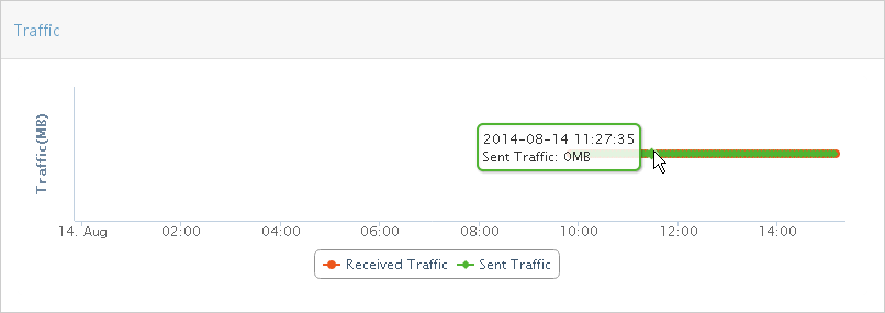
¡ Signal Strength
Figure 13 shows signal strength of the SIM card at each time point in a specified time range.
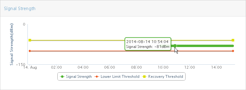
¡ Online Status
Figure 14 shows online status of the SIM card at each time point in a specified time range. Each vertical line indicates an online status change of the SIM card at a specific time point.
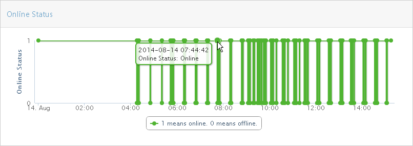
Setting signal strength thresholds for a SIM card
This field is available only for online devices.
To set signal strength thresholds for a SIM card:
1. Click the Service tab.
2. From the navigation tree, select MBM > Performance Management.
All mobile branch devices are displayed in the device list.
3. Click the icon ![]() next to the target phone number in the Device
List.
next to the target phone number in the Device
List.
4. Set RSSI Trap Lower Threshold (dBm).
When the signal strength is lower than the lower threshold, the device automatically sends a trap to IMC.
5. Set RSSI Trap Restore Threshold (dBm).
When the signal strength is higher than the restore threshold, the device automatically sends a restore trap to IMC.
|
|
NOTE: IMC can receive the traps only when the destination address of traps on the device is IMC. |
6. Click OK.
Configuring MBM options
MBM option management allows you to configure parameters that are globally effective on the MBM system and essential for MBM functions, including:
· SMS Gateway Configuration—MBM uses the SMS gateway to send SMS messages to mobile branch devices during SMS deployment.
· BIMS Parameter Configuration—The BIMS parameter configuration is sent to mobile branch devices through SMS messages. A mobile branch device can be managed by BIMS after it uses the information to establish a connection with the BIMS server.
· Lock Mobile Area—Allows you to specify a mobile area by radius for each mobile branch device. Users can access the network through the mobile branch device only when the device is within the area. The radius is centered around the latitude/longitude of a device when the locked device first came online, or when the device's update state is changed from Manual to Auto. When the device is out of the specified mobile area, the system can log off the device's SIM card user, add the user to the blacklist, or send traps to IMC, depending on your configuration.
· UAM Server Configuration—The UAM parameter settings enable MBM to work with UAM to manage mobile branch devices.
To access the Option Management page:
1. Click the Service tab.
2. From the navigation tree, select MBM > Options.
The Option Management page appears.
Configuring an SMS gateway
1. In the SMS Gateway Configuration area, click Select Device next to the SMS Gateway field.
The Select Devices window appears.
2. Select a device as the SMS gateway and click OK.
MBM auto-populates the management IP address of the selected device in the SMS Gateway field.
Make sure the SMS gateway is configured to send traps to IMC.
3. Enter the maximum number of transmission attempts in the Transmission Times field.
4. Enter the transmission timeout time in the Timeout (s) field.
If the mobile branch device fails to respond within the timeout time, MBM determines that the message delivery failed.
5. Click OK.
Configuring BIMS parameters
1. In the BIMS Parameter Configuration area, enter the URL of the ACS in the ACS URL field.
BIMS manages mobile branch devices through the ACS. Mobile branch devices access the specified URL to establish connections with the ACS.
2. Enter the user name and password used to access the ACS.
3. Click OK.
Lock Mobile Area
1. In the Lock Mobile Area area, select the Mobile Area Locking option to enable Lat&LNG global blocking, and go to Step 2.
To disable Lat&LNG global blocking, clear the option, and go to Step 4.
2. Specify the mobile area by radius for each mobile branch device in the Lock Radius (meters) field. Users can access the network through the mobile branch device only when the device is within the area.
3. Select the action to take when MBM detects a mobile branch device that is out of the mobile area:
¡ Log User Off—Logs off the device's SIM card user.
¡ Add to Blacklist—Adds the device's SIM card user to the blacklist.
¡ Send Traps—Sends traps to IMC.
4. Click OK.
Configuring the UAM server
1. In the UAM Server Configuration area, select the Configure UAM option.
2. Enter the IP address of the UAM server in the Server Address field.
3. The Username used to access the UAM server is Admin by default, and cannot be modified.
4. Enter the admin password in the Password field.
5. Click OK.
Managing BIMS reports
BIMS reports display statistics and performance information about CPEs in graphs. BIMS reports provided by MBM display performance statistics about mobile branch devices and SIM cards.
BIMS predefines multiple types of report templates, which can generate real-time reports and scheduled reports. BIMS reports can also be customized, which requires purchasing and installing IMC iAR.
Basic functions, such as adding shortcuts, modifying, deleting, exporting, and printing BIMS reports, are the same as IMC Platform reports. For basic report operations, see H3C Intelligent Management Center Enterprise and Standard Platform Administrator Guide.
Managing a real-time report
Real-time reports, which can be printed, enable the administrator to view statistics in a specific time range. Data in these reports can be saved locally.
Viewing a real-time report
1. Click the Report tab.
2. From the navigation tree, select Reports > Report Template List.
The Report Template List page appears.
3. In the Query Template area, select BIMS Report from the Type list, and then click Query.
The Report Template List displays all the BIMS reports.
4. Click the template name for the report you want to view.
The page for configuring report parameters appears.
5. Configure the required parameters, and click OK.
The available parameters vary with the report templates.
Branch Device Flow Statistic Report
A branch device flow statistic report displays the sent traffic, received traffic, and total traffic of mobile branch devices in the specified time range.
To view a branch device flow statistic report, configure the following parameters:
· Parameter "Begin Time" and "End Time"—Select a statistics collection time range from the list. You can select a specific time range, such as Last Hour, Last Week, or Last Month, or select Custom Range, and then specify the start time and end time.
· Location—Select a statistics collection location range from the list: All Devices or a location view.
· Begin Time/End Time—These two parameters appear only when you select Custom Range. Click Begin Time/End Time, and then select the begin time/end time in the calendar that appears.
Figure 15 shows a branch device flow statistic report.
Figure 15 Branch Device Flow Statistic Report
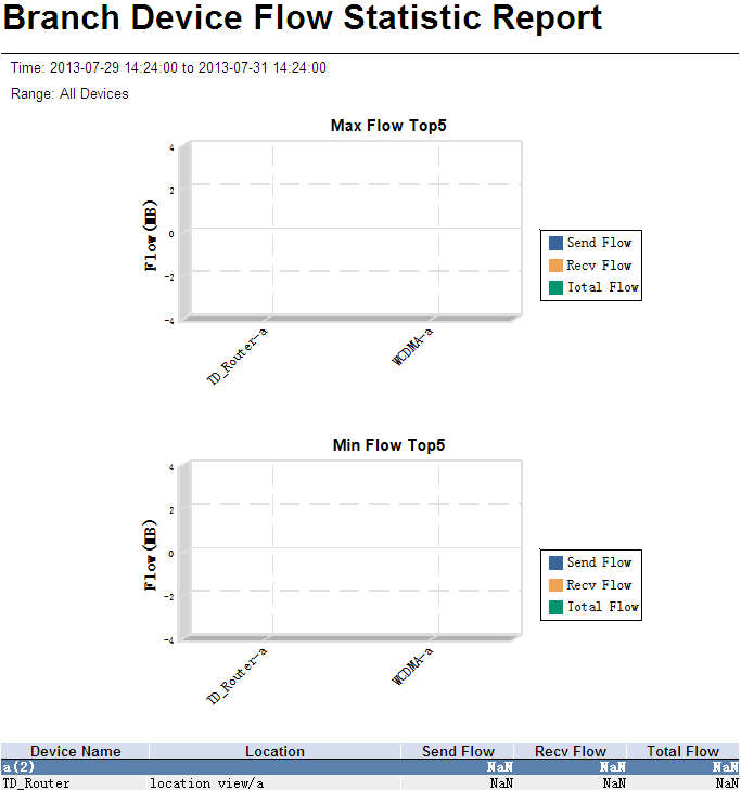
Branch Device Flow Statistic Report parameters:
· Time—Statistics collection time range.
· Range—Statistics collection location range: All Devices or a location view.
The Max Flow Top5 chart shows the top five mobile branch devices with the most total traffic in the specified time range. The sent traffic, received traffic, and total traffic of the top five mobile branch devices in the time range are also shown in the chart.
The Min Flow Top5 chart shows top five mobile branch devices with the least total traffic in the specified time range. The sent traffic, received traffic, and total traffic of the top five mobile branch devices in the time range are also shown in the chart.
Branch Device Flow Statistic Report fields:
· Device Name—Mobile branch device name.
· Location—Location view to which the mobile branch device belongs.
· Send Flow—Sent traffic of a mobile branch device in the specified time range.
· Recv Flow—Received traffic of a mobile branch device in the specified time range.
· Total Flow—Sent and received traffic of a mobile branch device in the specified time range.
Branch Device Inventory Report
A branch device inventory report displays information about mobile branch devices managed by MBM, and their locations.
To view a branch device inventory report, configure the Location parameter by selecting All Devices, or a location view to define a statistics collection location range.
Figure 16 shows a branch device inventory report.
Figure 16 Branch Device Inventory Report
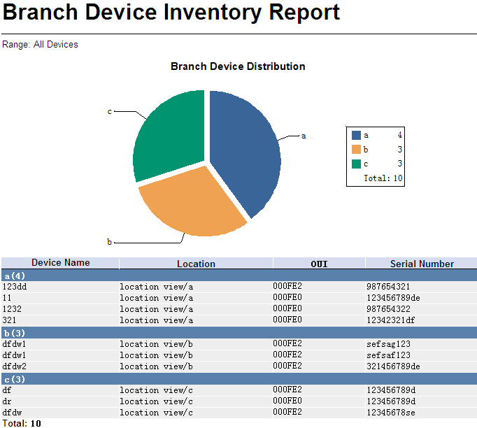
The branch device inventory report has only the Range parameter, which can be All Devices or a location view. This parameter defines a statistics collection location range.
Based on the location view, the Branch Device Distribution pie chart displays the location distribution of branch devices in the specified location range.
Branch Device Inventory Report fields:
· Device Name—Mobile branch device name.
· Location—Location view to which the mobile branch device belongs.
· OUI—The organizationally unique identifier number of the vendor.
· Serial Number—Serial number of the mobile branch device.
· Location View(n)—There are n mobile branch devices in the location view, where n refers to the number of mobile branch devices.
CPE Asset Report
A CPE asset report displays CPE device information, software version, and hardware version in BIMS.
Figure 17 shows a CPE asset report.

CPE Asset Report fields:
· CPE Name—CPE name.
· IP Address—CPE IP address.
· Vendor—CPE vendor.
· OUI—The organizationally unique identifier number of the vendor.
· Serial ID—CPE serial ID.
· Hardware Version—CPE hardware version.
· Software Version—CPE software version.
CPE Connectivity Counts Report
A CPE connectivity counts report displays CPE connectivity count statistics of the specified CPEs in the specified time range.
To view a CPE connectivity counts report, configure the following parameters:
· Parameter "Begin Time" and "End Time"—Select a statistics collection time range from the list. You can select a specific time range, such as Last Hour, Last Day, Last Week, or Last Month, or select Custom Range, and then specify the start time and end time manually.
· CPE Group—Select a statistics collection range, a CPE group or ALL CPEs, from the list.
· Begin Time/End Time—These two parameters appear only when you select Custom Range. Click Begin Time/End Time, and then select the begin time/end time in the calendar that appears.
Figure 18 shows a CPE connectivity counts report.
Figure 18 CPE Connectivity Counts Report
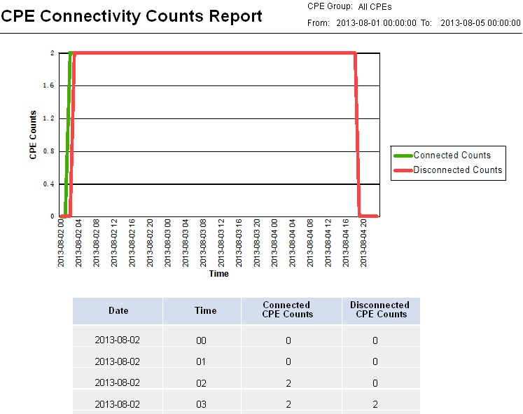
CPE Connectivity Counts Report parameters:
· CPE Group—Statistics collection range: a CPE group or ALL CPEs.
· From To—Statistics collection time range.
The CPE Counts trend graph displays counts of connected CPEs and disconnected CPEs during the specified time range.
CPE Connectivity Counts Report fields:
· Date—Report date.
· Time—Report time. The sampling time interval is one hour.
· Connected CPE Counts—Total number of CPEs connected to the ACS in the specified time range.
· Disconnected CPE Counts—Total number of CPEs disconnected from the ACS in the specified time range.
CPE Connectivity Detail Report
A CPE connectivity detail report displays detailed CPE connectivity information about the specified CPEs in the specified time range.
To view a CPE connectivity detail report, configure the following parameters:
· Parameter "Begin Time" and "End Time"—Select a statistics collection time range from the list. You can select a specific time range, such as Last Hour, Last Day, Last Week, or Last Month, or select Custom Range, and then specify the start time and end time.
· CPE Group—Select a statistics collection range: a CPE group or ALL CPEs.
· Begin Time/End Time—These two parameters appear only when you select Custom Range. Click Begin Time/End Time, and then select the beginning time and ending time in the calendar that appears.
Figure 19 shows a CPE connectivity detail report.
Figure 19 CPE Connectivity Detail Report
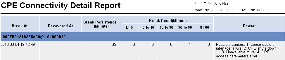
CPE Connectivity Detail Report parameters:
· CPE Group—Statistics collection range: a CPE group or ALL CPEs.
· From To—Statistics collection time range.
CPE Connectivity Detail Report fields:
· Break At—Time stamp when a break occurred.
· Recovered At—Time stamp when a break is recovered.
· Break Persistence (Minute)—Break duration, in minutes.
· Break Detail (Minute):
¡ LT 5—Number of breaks recovered in less than 5 minutes.
¡ 5 to 10—Number of breaks recovered in 5 to 10 minutes.
¡ 10 to 30—Number of breaks recovered in 10 to 30 minutes.
¡ 30 to 60—Number of breaks recovered in 30 to 60 minutes.
¡ GT 60—Number of breaks recovered in more than 60 minutes.
· Reason—Possible reason causing the break.
CPE Connectivity Summary Report
A CPE connectivity summary report displays CPE connectivity summary information of the specified CPEs in the specified time range.
To view a CPE connectivity summary report, configure the following parameters:
· Parameter "Begin Time" and "End Time"—Select a statistics collection time range from the list. You can select a specific time range, such as Last Hour, Last Day, Last Week, or Last Month, or select Custom Range, and then specify the start time and end time.
· CPE Group—Select the statistics collection range: a CPE group or ALL CPEs.
· Begin Time/End Time—These two parameters appear only when you select Custom Range. Click Begin Time/End Time, and then select the beginning time and ending time in the calendar that appears.
Figure 20 shows a CPE connectivity summary report.
Figure 20 Connectivity Summary Report
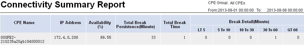
CPE Connectivity Summary Report parameters:
· CPE Group—Statistics collection range: a CPE group or ALL CPEs.
· From To—Statistics collection time range.
CPE Connectivity Summary Report fields:
· CPE Name—CPE names.
· IP Address—IP addresses of CPEs.
· Availability (%)—Ratio of the time a CPE was connected to the ACS to the time span specified on the Set Parameter page.
· Total Break Persistence (Minute)—Total duration of all the breaks that occurred within the specified period of time, in minutes.
· Total Break Time—Total number of the breaks that occurred within the specified period of time.
· Break Detail (Minute):
¡ LT 5—Number of breaks recovered in less than 5 minutes.
¡ 5 to 10—Number of breaks recovered in 5 to 10 minutes.
¡ 10 to 30—Number of breaks recovered in 10 to 30 minutes.
¡ 30 to 60—Number of breaks recovered in 30 to 60 minutes.
¡ GT 60—Number of breaks recovered in more than 60 minutes.
Device Flow Monthly Statistic Report
A device flow monthly statistic report displays traffic statistics of mobile branch devices in the specified time range.
To view a device flow monthly statistic report, configure the following parameters:
· View/Device Name—Select a statistics collection target range from the list: location views or devices.
· End Time—Click End Time, and then select the end time in the calendar that appears. The statistics collection time range is from the the first day of the month to the end time.
Figure 21 shows a device flow monthly statistic report.
Figure 21 Device Flow Monthly Statistic Report

Device Flow Monthly Statistic Report parameters:
· Statistic Time—Statistics collection time range.
· Unit—Unit of the collected statistics, which is megabytes (MB).
The Device Flow Top10 chart displays the top 10 devices with the most total traffic in the specified time range.
Device Flow Monthly Statistic Report fields:
· Device Name—Name of the mobile branch device.
· Phone Num—Phone number of the SIM card on the mobile branch device.
· Provider—Service provider view of the SIM card on the mobile branch device.
· Location—Location view of the mobile branch device.
· 1 to 31—Daily traffic in the specified time range.
· Total Flow—Total traffic in the specified time range.
Device Flow Year Statistic Report
A device flow year statistic report displays traffic statistics of mobile branch devices in the specified time range.
To view a device flow year statistic report, configure the following parameters:
· View/Device Name—Select a statistics collection target range from the list: location views or devices.
· Start Time/End Time—Click Start Time/End Time, and then select the start time/end time in the calendar that appears.
Figure 22 shows a device flow year statistic report.
Figure 22 Device Flow Year Statistic Report

Device Flow Year Statistic Report parameters:
· Statistic Time—Statistics collection time range.
· Unit—Unit of the collected statistics, which is megabytes (MB).
The Device Flow Top10 chart displays the top 10 devices with the most total traffic in the specified time range.
Device Flow Year Statistic Report fields:
· Device Name—Name of the mobile branch device.
· Phone Num—Phone number of the SIM card on the mobile branch device.
· Provider—Service provider view of the SIM card on the mobile branch device.
· Location—Location view of the mobile branch device.
· Jan~Dec—Monthly traffic in the specified time range.
· Total Flow—Total traffic in the specified time range.
Device Signal Strength Monthly Statistic Report
A device signal strength monthly statistic report displays signal strength statistics of mobile branch devices in the specified time range.
To view a device signal strength monthly statistic report, configure the following parameters:
· View/Device Name—Select a statistics collection target range from the list: location views or devices.
· End Time—Click End Time, and then select the end time in the calendar that appears. The statistics collection time range is from the first day of the month to the end time.
Figure 23 shows a device signal strength monthly statistic report.
Figure 23 Device Signal Strength Monthly Statistic Report

Device Signal Strength Monthly Statistic Report parameters:
· Statistic Time—Statistics collection time range.
· Unit—Unit of the collected statistics, which is dBm.
The worst Top10 RSSI of the Device chart displays the top 10 devices with the worst signal strength in the specified time range.
Device Signal Strength Monthly Statistic Report fields:
· Device Name—Name of the mobile branch device.
· Phone Num—Phone number of the SIM card on the mobile branch device.
· Provider—Service provider view of the SIM card on the mobile branch device.
· Location—Location view of the mobile branch device.
· 1 to 31—Average daily signal strength in the specified time range.
· Avg—Average signal strength in the specified time range.
Device Signal Strength Year Statistic Report
A device signal strength year statistic report displays signal strength statistics of mobile branch devices in the specified time range.
To view a device signal strength year statistic report, configure the following parameters:
· View/Device Name—Select a statistics collection target range: location views or devices.
· Start Time/End Time—Click Start Time/End Time, and then select the start time/end time in the calendar that appears.
Figure 24 shows a device signal strength year statistic report.
Figure 24 Device Signal Strength Year Statistic Report
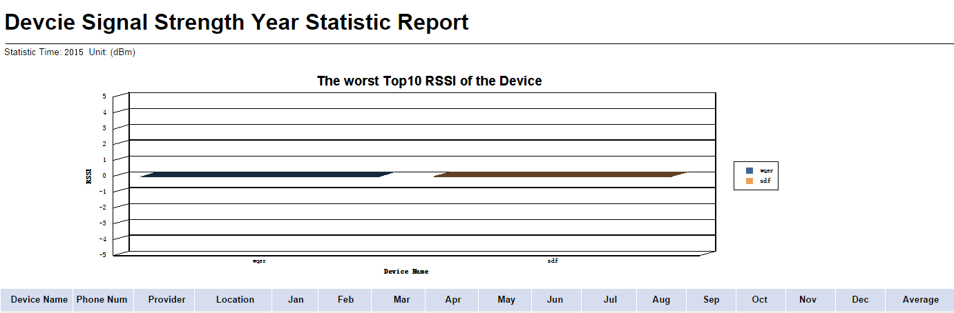
Device Signal Strength Year Statistic Report parameters:
· Statistic Time—Statistics collection time range.
· Unit—Unit of the collected statistics, which is dBm.
The worst Top10 RSSI of the Device chart displays the top 10 devices with the worst signal strength in the specified time range.
Device Signal Strength Year Statistic Report fields:
· Device Name—Name of the mobile branch device.
· Phone Num—Phone number of the SIM card on the mobile branch device.
· Provider—Service provider view of the SIM card on the mobile branch device.
· Location—Location view of the mobile branch device.
· Jan~Dec—Average monthly signal strength in the specified time range.
· Avg—Average signal strength in the specified time range.
Device Up Down Time Period Report
A device up down time period report displays online time, online duration, and offline time of mobile branch devices in the specified time range.
To view a device up down time period report, configure the following parameters:
· Device—Select a statistics collection target by specifying a mobile branch device from the list.
· Start Time/End Time—Click Start Time/End Time, and then select the start time/end time in the calendar that appears.
Figure 25 shows a device up down time period report.
Figure 25 Device Up Down Time Period Report

Device up down time period report parameters:
· Statistic Time—Statistics collection time range.
Device up down time period report fields:
· Device Name—Name of the mobile branch device.
· Phone Number—Phone number of the SIM card on the mobile branch device.
· Up Time—Time when the mobile branch device came online.
· Down Time—Time when the mobile branch device went offline.
· Time Period(Min)—Device online duration.
Device Up Duration Monthly Statistic Report
A device up duration monthly statistic report displays online duration of mobile branch devices in the specified time range.
To view a device up duration monthly statistic report, configure the following parameters:
· View/Device Name—Select a statistics collection targets range, specified location views or devices, from the list.
· End Time—Click End Time, and then select the end time in the calendar that appears. The statistics collection time range is from the first day of the month to the end time.
Figure 26 shows a device up duration monthly statistic report.
Figure 26 Device Up Duration Monthly Statistic Report

Device Up Duration Monthly Statistic Report parameters:
· Statistic Time—Statistics collection time range.
· Unit—Unit of the collected statistics, which is hours.
The Device Up Duration Top10 chart displays the top 10 devices with the longest online duration in the specified time range.
Device Up Duration Monthly Statistic Report fields:
· Device Name—Name of the mobile branch device.
· Phone Num—Phone number of the SIM card on the mobile branch device.
· Provider—Service provider view of the SIM card on the mobile branch device.
· Location—Location view of the mobile branch device.
· 1 to 31—Daily device online duration in the specified time range.
· Total—Total device online duration in the specified time range.
Device Up Duration Year Statistic Report
A device up duration year statistic report displays online duration of mobile branch devices in the specified time range.
To view a device up duration year statistic report, configure the following parameters:
· View/Device Name—Select a statistics collection target range from the list: location views or devices.
· Start Time/End Time—Click Start Time/End Time, and then select the start time/end time in the calendar that appears.
Figure 27 shows a device up duration year statistic report.
Figure 27 Device Up Duration Year Statistic Report

Device Up Duration Year Statistic Report parameters:
· Statistic Time—Statistics collection time range.
· Unit—Unit of the collected statistics, which is hours.
The Device Up Duration Top10 chart displays the top 10 devices with the longest online duration in the specified time range.
Device Up Duration Year Statistic Report fields:
· Device Name—Name of the mobile branch device.
· Phone Num—Phone number of the SIM card on the mobile branch device.
· Provider—Service provider view of the SIM card on the mobile branch device.
· Location—Location view of the mobile branch device.
· Jan~Dec—Monthly device online duration in the specified time range.
· Total—Total device online duration in the specified time range.
Device Up Statistic Report
A device up statistic report displays the online time, online duration, and signal strength of all mobile branch devices in the specified time range.
To view a device up statistic report, configure the following parameters:
· Parameter "Begin Time" and "End Time"—Select a statistics collection time range from the list. You can select a specific time range, such as Last Hour, Last Day, Last Week, or Last Month, or select Custom Range, and then specify the start time and end time.
· Begin Time/End Time—These two parameters appear only when you select Custom Range. Click Begin Time/End Time, and then select the begin time/end time in the calendar that appears.
Figure 28 shows a device up statistic report.
Figure 28 Device Up Statistic Report
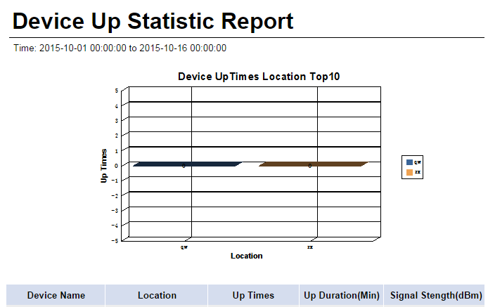
Device Up Statistic Report parameters:
· Statistic Time—Statistics collection time range.
The Device Up Times Location Top10 chart displays the top 10 devices with the longest online duration in the specified time range.
Device Up Statistic Report fields:
· Device Name—Name of the mobile branch device.
· Location—Location view of the mobile branch device.
· Up Times—Number of times that the mobile branch device comes online in the specified time range.
· Up Duration(Min)—Device online duration in the specified time range.
· Signal Strength(dBm)—Average device signal strength in the specified time range.
Inactive Device Statistic Report
An inactive device statistic report displays statistics about the top 10 devices with the shortest online duration in the specified time range.
To view an inactive device statistic report, configure the following parameters:
· Begin Time/End Time—Click Begin Time/End Time, and then select the begin time/end time in the calendar that appears.
Figure 29 shows a inactive device statistic report.
Figure 29 Inactive Device Statistic Report
Inactive Device Statistic Report parameters:
· Statistic Time—Statistics collection time range.
The Inactive Device Top10 chart displays the top 10 devices with the shortest online duration in the specified time range.
Inactive Device Statistic Report fields:
· Device Name—Name of the mobile branch device.
· Location—Location view of the mobile branch device.
· Up Duration(Min)—Device online duration in the specified time range.
· Last Up Time—The most recent time when the device came online in the specified time range.
One Device Flow Monthly Statistic Report
A one device flow monthly statistic report displays total traffic statistics of a mobile branch device in the specified time range.
To view a one device flow monthly statistic report, configure the following parameters:
· Device—Select a statistics collection target from the list by specifying a mobile branch device.
· End Time of Month—Click End Time of Month, and then select the end time in the calendar that appears. The statistics collection time range is from the first day of the month to the end time.
Figure 30 shows a one device flow monthly statistic report.
Figure 30 One Device Flow Monthly Statistic Report
One Device Flow Monthly Statistic Report parameters:
· Statistic Time—Statistics collection time range.
· Unit—Unit of the collected statistics, which is megabytes (MB).
One Device Flow Monthly Statistic Report fields:
· Device Name—Name of the mobile branch device.
· Phone Num—Phone number of the SIM card on the mobile branch device.
· Provider—Service provider view of the SIM card on the mobile branch device.
· Location—Location view of the mobile branch device.
· 1 to 31—Daily traffic in the specified time range.
· Total—Total traffic in the specified time range.
One Device Flow Year Statistic Report
A one device flow year statistic report displays total traffic statistics of a mobile branch device in the specified time range.
To view a one device flow year statistic report, configure the following parameters:
· Device—Select a statistics collection target from the list by specifying a mobile branch device.
· Begin Time/End Time—Click Begin Time/End Time, and then select the begin time/end time in the calendar that appears.
Figure 31 shows a one device flow year statistic report.
Figure 31 One Device Flow Year Statistic Report
![]()
One Device Flow Year Statistic Report parameters:
· Statistic Time—Statistics collection time range.
· Unit—Unit of the collected statistics, which is megabytes (MB).
One Device Flow Year Statistic Report fields:
· Device Name—Name of the mobile branch device.
· Phone Num—Phone number of the SIM card on the mobile branch device.
· Provider—Service provider view of the SIM card on the mobile branch device.
· Location—Location view of the mobile branch device.
· Jan~Dec—Monthly traffic in the specified time range.
· Total—Total traffic in the specified time range.
One Device Signal Strength Monthly Statistic Report
A one device signal strength monthly statistic report displays signal strength statistics of a mobile branch device in the specified time range.
To view a one device signal strength monthly statistic report, configure the following parameters:
· Device—Select a statistics collection target from the list by specifying a mobile branch device.
· End Time of Month—Click End Time of Month, and then select the end time in the calendar that appears. The statistics collection time range is from the first day of the month to the end time.
Figure 32 shows a one device signal strength monthly statistic report.
Figure 32 One Device Signal Strength Monthly Statistic Report

One Device Signal Strength Monthly Statistic Report parameters:
· Statistic Time—Statistics collection time range.
· Unit—Unit of the collected statistics, which is dBm.
One Device Signal Strength Monthly Statistic Report fields:
· Device Name—Name of the mobile branch device.
· Phone Num—Phone number of the SIM card on the mobile branch device.
· Provider—Service provider view of the SIM card on the mobile branch device.
· Location—Location view of the mobile branch device.
· 1 to 31—Average daily signal strength in the specified time range.
· Avg—Average signal strength in the specified time range.
One Device Signal Strength Year Statistic Report
A one device signal strength year statistic report displays signal strength statistics of a mobile branch device in the specified time range.
To view a one device signal strength monthly statistic report, configure the following parameters:
· Device—Select a statistics collection target from the list by specifying a mobile branch device.
· Begin Time/End Time—Click Begin Time/End Time, and then select the begin time/end time in the calendar that appears.
Figure 33 shows a one device signal strength year statistic report.
Figure 33 One Device Signal Strength Year Statistic Report
![]()
One Device Signal Strength Year Statistic Report parameters:
· Statistic Time—Statistics collection time range.
· Unit—Unit of the collected statistics, which is dBm.
One Device Signal Strength Year Statistic Report fields:
· Device Name—Name of the mobile branch device.
· Phone Num—Phone number of the SIM card on the mobile branch device.
· Provider—Service provider view of the SIM card on the mobile branch device.
· Location—Location view of the mobile branch device.
· Jan~Dec—Average monthly signal strength in the specified time range.
· Average—Average signal strength in the specified time range.
One Device Up Duration Monthly Statistic Report
A one device up duration monthly statistic report displays online duration of a mobile branch device in the specified time range.
To view a one device up duration monthly statistic report, configure the following parameters:
· Device—Select a statistics collection target from the list by specifying a mobile branch device.
· End Time—Click End Time, and then select the end time in the calendar that appears. The statistics collection time range is from the first day of the month to the end time.
Figure 34 shows a one device up duration monthly statistic report.
Figure 34 One Device Up Duration Monthly Statistic Report

One Device Up Duration Monthly Statistic Report parameters:
· Statistic Time—Statistics collection time range.
· Unit—Unit of the collected statistics, which is hours.
Device Up Duration Monthly Statistic Report fields:
· Device Name—Name of the mobile branch device.
· Phone Num—Phone number of the SIM card on the mobile branch device.
· Provider—Service provider view of the SIM card on the mobile branch device.
· Location—Location view of the mobile branch device.
· 1 to 31—Daily device online duration in the specified time range.
· Total—Total device online duration in the specified time range.
One Device Up Duration Year Statistic Report
A one device up duration year statistic report displays online duration of a mobile branch device in the specified time range.
To view a one device up duration year statistic report, configure the following parameters:
· Device—Select a statistics collection target from the list by specifying a mobile branch device.
· Start Time/End Time—Click Start Time/End Time, and then select the start time/end time in the calendar that appears.
Figure 35 shows a one device up duration year statistic report.
Figure 35 One Device Up Duration Year Statistic Report

One Device Up Duration Year Statistic Report parameters:
· Statistic Time—Statistics collection time range.
· Unit—Unit of the collected statistics, which is hours.
One Device Up Duration Year Statistic Report fields:
· Device Name—Name of the mobile branch device.
· Phone Num—Phone number of the SIM card on the mobile branch device.
· Provider—Service provider view of the SIM card on the mobile branch device.
· Location—Location view of the mobile branch device.
· Jan~Dec—Monthly device online duration in the specified time range.
· Total—Total device online duration in the specified time range.
Phone Flow Statistic Report
A phone flow statistic report displays the sent traffic, received traffic, and total traffic of SIM cards on mobile branch devices in the specified time range.
To view a phone flow statistic report, configure the following parameters:
· Parameter "Begin Time" and "End Time"—Select a statistics collection time range from the list. You can select a specific time range, such as Last Hour, Last Week, or Last Month, or select Custom Range, and then specify the start time and end time.
· Provider—Select a statistics collection range from the list: All SIM Cards or a service provider view.
· Location—Select a statistics collection location range from the list: All Devices or a location view.
· Begin Time/End Time—These two parameters appear only when you select Custom Range. Click Begin Time/End Time, and then select the begin time/end time in the calendar that appears.
Figure 36 shows a phone flow statistic report.
Figure 36 Phone Flow Statistic Report

Phone Flow Statistic Report parameters:
· Time—Statistics collection time range.
· Location—Statistics collection location range: All Devices or a location view.
· Provider—Statistics collection range: All SIM Cards or a service provider view.
The Max Flow Top5 chart displays the top five SIM cards with the most total traffic in the specified time range. The sent traffic, received traffic, and total traffic of the top five SIM cards in the time range, are also shown in the chart.
The Min Flow Top5 chart shows the top five SIM cards with the least total traffic in the specified time range. The sent traffic, received traffic, and total traffic of the top five SIM cards in the time range, are also shown in the chart.
Phone Flow Statistic Report fields:
· Phone Number—Phone number of the SIM card on the mobile branch device.
· IMSI—IMSI number of the SIM card on the mobile branch device.
· Device Name—Name of the mobile branch device to which the SIM card belongs.
· Location—Location view of the mobile branch device to which the SIM card belongs.
· Send Flow—Sent traffic of the SIM card in the specified time range.
· Recv Flow—Received traffic of the SIM card in the specified time range.
· Total Flow—Sent traffic and received traffic of the SIM card in the specified time range.
Phone Inventory Report
A phone inventory report displays information about SIM cards managed by MBM, location distribution, and provider distribution.
To view a phone inventory report, configure the following parameters:
· Provider—Select a statistics collection range from the list: All SIM Cards or a service provider view.
· Location—Select a statistics collection location range from the list: All Devices or a location view.
Figure 37 shows a phone inventory report.
Figure 37 Phone Inventory Report
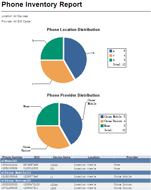
Phone Inventory Report parameters:
· Location—Statistics collection location range: All Devices or a location view.
· Provider—Statistics collection range: All SIM Cards or a service provider view.
Based on the location view, the Phone Location Distribution pie chart displays the location distribution of SIM cards in the specified location range.
Based on the service provider view, the Phone Provider Distribution pie chart displays the provider distribution of SIM cards in the specified location range.
Phone Inventory Report fields:
· Phone Number—Phone number of the SIM card on the mobile branch device.
· IMSI—IMSI number of the SIM card on the mobile branch device.
· Device Name—Name of the mobile branch device to which the SIM card belongs.
· Location—Location view of the mobile branch device to which the SIM card belongs.
· Provider—Service provider view of the SIM card.
· Location View\Service Provider View(n)—There are n SIM cards that belong to the service provider view in the location view, where n refers to the number of SIM cards.
Phone Rate Statistic Report
A phone rate statistic report displays the sending rate, receiving rate, and total rate of SIM cards on mobile branch devices in the specified time range.
To view a phone rate statistic report, configure the following parameters:
· Parameter "Begin Time" and "End Time"—Select a statistics collection time range from the list. You can select a specific time range, such as Last Hour, Last Week, or Last Month, or select Custom Range, and then specify the start time and end time.
· Provider—Select a statistics collection range from the list: All SIM Cards or a service provider view.
· Location—Select a statistics collection location range from the list: All Devices or a location view.
· Begin Time/End Time—These two parameters appear only when you select Custom Range. Click Begin Time/End Time, and then select the begin time/end time in the calendar that appears.
Figure 38 shows a phone rate statistic report.
Figure 38 Phone Rate Statistic Report

Phone Rate Statistic Report parameters:
· Time—Statistics collection time range.
· Location—Statistics collection location range: All Devices or a location view.
· Provider—Statistics collection range: All SIM Cards or a service provider view.
The Max Rate Top5 chart shows the top five SIM cards with the highest rate in the specified time range. The sending rate, receiving rate, and total rate of the top five SIM cards in the time range, are also shown in the chart.
The Min Rate Top5 chart shows the top five SIM cards with the lowest rate in the specified time range. The sending rate, receiving rate, and total rate of the top five SIM cards in the time range, are also shown in the chart.
Phone Rate Statistic Report fields:
· Phone Number—Phone number of the SIM card on the mobile branch device.
· IMSI—IMSI number of the SIM card on the mobile branch device.
· Device Name—Name of the mobile branch device to which the SIM card belongs.
· Location—Location view of the mobile branch device to which the SIM card belongs.
· Send Rate—Sending rate of the SIM card in the specified time range.
· Recv Rate—Receiving rate of the SIM card in the specified time range.
· Total Rate—Sending rate and receiving rate of the SIM card in the specified time range.
Phone Signal Strength Detail Report
A phone signal strength detail report displays the signal strength details of a SIM card on a mobile branch device in the specified time range.
To view a phone signal strength detail report, configure the following parameters:
· Parameter "Begin Time" and "End Time"—Select a statistics collection time range from the list. You can select a specific time range, such as Last Hour, Last Week, or Last Month, or select Custom Range, and then specify the start time and end time.
· Phone Number—Select a SIM card number to be measured from the Phone Number list in the Device-Phone Number format.
· Begin Time/End Time—These two parameters appear only when you select Custom Range. Click Begin Time/End Time, and then select the begin time/end time in the calendar that appears.
Figure 39 shows a phone signal strength detail report.
Figure 39 Phone Signal Strength Detail Report
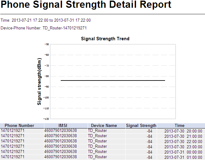
Phone Signal Strength Detail Report parameters:
· Time—Statistics collection time range.
· Device-Phone Number—Device name and SIM card number used for data collection.
The Signal Strength Trend graph displays the signal strength change of a SIM card on a mobile branch device in the specified time range.
Phone Signal Strength Detail Report fields:
· Phone Number—Phone number of the SIM card on the mobile branch device.
· IMSI—IMSI number of the SIM card on the mobile branch device.
· Device Name—Name of the mobile branch device to which the SIM card belongs.
· Signal Strength—Signal strength of the SIM card.
· Time—Data collection interval. The default data collection interval is 1 hour.
Phone Signal Strength Summary Report
A phone signal strength summary report displays signal strength statistics of SIM cards on mobile branch devices in the specified time range.
To view a phone signal strength summary report, configure the following parameters:
· Parameter "Begin Time" and "End Time"—Select a statistics collection time range from the list. You can select a specific time range, such as Last Hour, Last Week, or Last Month, or select Custom Range, and then specify the start time and end time.
· Provider—Select a statistics collection range from the list: All SIM Cards or a service provider view.
· Location—Select a statistics collection location range from the list: All Devices or a location view.
· Begin Time/End Time—These two parameters appear only when you select Custom Range. Click Begin Time/End Time, and then select the begin time/end time in the calendar that appears.
Figure 40 shows a phone signal strength summary report.
Figure 40 Phone Signal Strength Summary Report
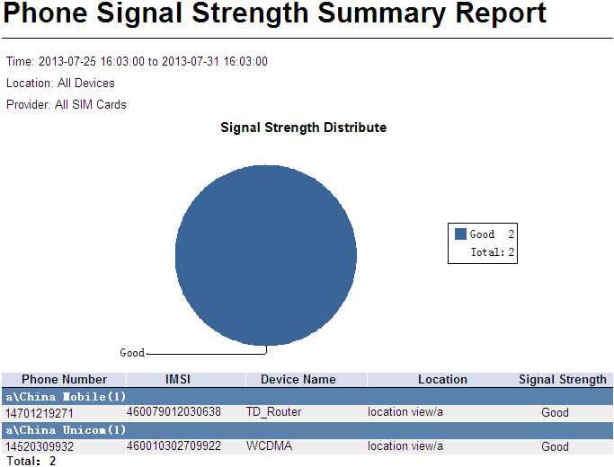
Phone Signal Strength Summary Report parameters:
· Time—Statistics collection time range.
· Location—Statistics collection location range: All Devices or a location view.
· Provider—Statistics collection range: All SIM Cards or a service provider view.
The Signal Strength Distribute chart displays the distribution of signal strength levels (No Signal, Poor, Low, Moderate, Good, and Excellent) of SIM cards on mobile branch devices.
Phone Signal Strength Summary Report fields:
· Phone Number—Phone number of the SIM card on the mobile branch device.
· IMSI—IMSI number of the SIM card on the mobile branch device.
· Device Name—Name of the mobile branch device to which the SIM card belongs.
· Location—Location view of the mobile branch device to which the SIM card belongs.
· Signal Strength—Signal strength level, including No Signal, Poor, Low, Moderate, Good, and Excellent.
· Location View\Service Provider View(n)—There are n SIM cards that belongs to the service provider view in the location view, where n refers to the number of SIM cards.
Managing a scheduled report
Scheduled reports are generated in a scheduled time period. The report generation period and report templates must be predefined. The administrator can view reports generated in different schedules, and compare and analyze the data in reports.
Adding a scheduled report
1. Enter the page for adding a scheduled report by using the following methods:
¡ Click the Report tab.
Select Reports > Add Scheduled Report from the navigation tree to enter the page for adding a scheduled report.
¡ Click the Report tab.
Select Scheduled Reports > All Scheduled Reports from the navigation tree to enter the All Scheduled Reports page.
Click Add to enter the page for adding a scheduled report.
2. Select a template:
a. On the right of Template Name, click Select.
b. From the Type list in the Query Template area, select BIMS Report, and then click Query.
c. Select the target report template, and click OK.
3. Enter the report name in the Scheduled Report Name field.
4. Select an operator group that can view the report in one or both of the following ways:
¡ Select an operator group from the page.
¡ Click the Operator Group Information icon
![]() to the right of the target operator group.
The Operator Group Information window appears.
to the right of the target operator group.
The Operator Group Information window appears.
Select an operator group in the Operator Group List area. The operators contained in the operator group are displayed on the right.
Click Close to the return to the page for adding a report.
All operators in the group can view the report.
5. Specify a generation period.
A scheduled report period is determined by both the schedule type and schedule time settings.
a. Schedule Type—Select a schedule type: Daily, Weekly, Monthly, Quarterly, Half Yearly, or Yearly.
b. Report Start Date—Click Report Start Date, and then select the start date in the calendar that appears.
6. Set the date at which a report becomes invalid. BIMS does not generate any scheduled report after this date. (This step is optional.)
To set the end date:
a. Select End by.
A box appears.
b. Click the box, and then select the end date in the calendar that appears.
7. Select a file format for the report from the Report File Format list. The available options include PDF, CSV, MS Excel, and MS Excel (Data-only).
8. Send a report by email:
Select Send by Email, and then enter the email address of the receiver. Reports can be sent to only one email address. (This step is optional.)
9. Specify the parameters for the report in the Parameter Value area.
The parameters required for adding a schedule report vary with the report templates.
10. Click OK.
Viewing a scheduled report
1. Click the Report tab.
2. From the navigation tree, select Scheduled Reports > All Scheduled Reports.
The All Scheduled Reports page appears.
3. Click the History
Report icon ![]() of the target scheduled report you want to view.
of the target scheduled report you want to view.
The History Report page appears.
4. Click View to open a report, or click Save to save the report locally.
Branch Device Flow Statistic Report
A branch device flow statistic report displays the sent traffic, received traffic, and total traffic of mobile branch devices in a schedule.
To add a branch device flow statistic report, configure the following parameters:
· Location—Click the Set
Parameter icon ![]() . The Set Parameter
page appears. Select a location view or All Devices for statistics collection,
and then click OK.
. The Set Parameter
page appears. Select a location view or All Devices for statistics collection,
and then click OK.
· Begin Time—Click the Set Parameter icon ![]() . The Set Parameter
page appears. Select the report start time, and then click OK.
. The Set Parameter
page appears. Select the report start time, and then click OK.
· End Time—Click the Set
Parameter icon ![]() . The Set Parameter page appears. Select the report end time,
and then click OK.
. The Set Parameter page appears. Select the report end time,
and then click OK.
Figure 41 shows a branch device flow statistic report.
Figure 41 Branch Device Flow Statistic Report

Branch Device Flow Statistic Report parameters:
· Time—Statistics collection time range.
· Range—Statistics collection location range, All Devices or a location view.
The Max Flow Top5 chart shows the top five mobile branch devices with the most total traffic in a schedule. The sent traffic, received traffic, and total traffic of the top five mobile branch devices in the schedule are also shown in the chart.
The Min Flow Top5 chart shows the top five mobile branch devices with the least total traffic in a schedule. The sent traffic, received traffic, and total traffic of the top five mobile branch devices in the schedule are also shown in the chart.
Branch Device Flow Statistic Report fields:
· Device Name—Mobile branch device name.
· Location—Location view to which the mobile branch device belongs.
· Send Flow—Sent traffic of the mobile branch device in a schedule.
· Recv Flow—Received traffic of the mobile branch device in a schedule.
· Total Flow—Sent traffic and received traffic of the mobile branch device in a schedule.
Branch Device Inventory Report
A branch device inventory report displays mobile branch device information and their location distribution in a schedule.
To add a branch device inventory report, configure the Location parameter as follows:
1. Click the Set Parameter
icon ![]() .
.
The Set Parameter page appears.
2. Select a location view or All Devices for statistics collection.
3. Click OK.
Figure 42 shows a branch device inventory report.
Figure 42 Branch Device Inventory Report
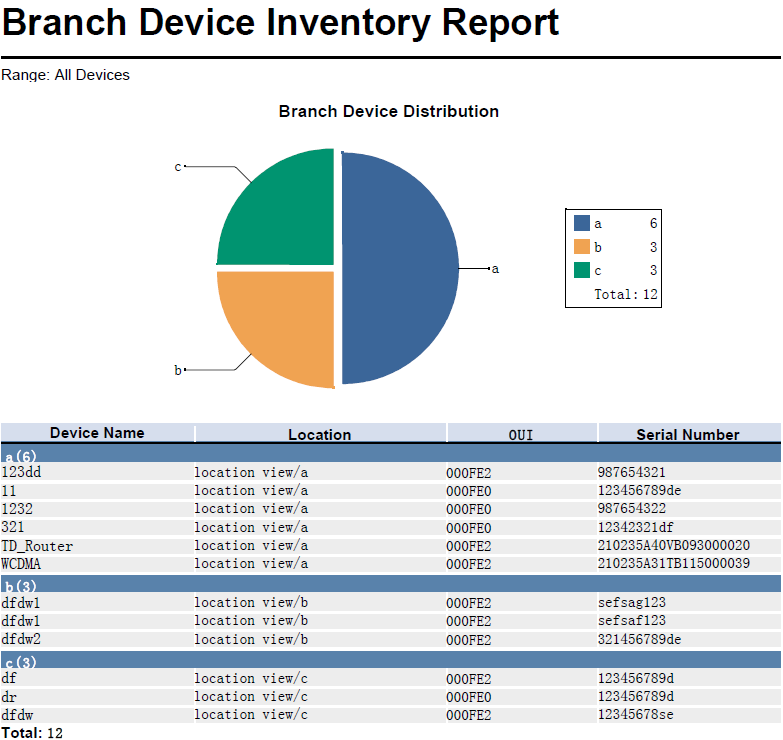
The branch device inventory report has only the Range parameter: All Devices or a location view. This parameter defines a statistics collection location range.
Based on the location view, the Branch Device Distribution pie chart displays the location distribution of mobile branch devices in the specified location range.
Branch Device Inventory Report fields:
· Device Name—Mobile branch device name.
· Location—Location view to which the mobile branch device belongs.
· OUI—The organizationally unique identifier number of the vendor.
· Serial Number—Serial number of the mobile branch device.
· Location View(n)—There are n mobile branch devices in the location view, where n refers to the number of mobile branch devices.
CPE Asset Report
A CPE asset report displays CPE device information, hardware version, and software version in a schedule.
Figure 43 shows a CPE asset report.
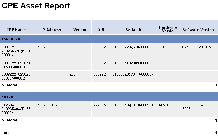
CPE Asset Report fields:
· CPE Name—CPE name.
· IP Address—CPE IP address.
· Vendor—CPE vendor.
· OUI— The organizationally unique identifier number of the vendor.
· Serial ID—CPE serial ID.
· Hardware Version—CPE hardware version.
· Software Version—CPE software version.
CPE Connectivity Count Report
A CPE connectivity count report displays connection statistics of the specified CPEs in a schedule.
To add a CPE connectivity count report, configure the following parameters:
· CPE Group—Click the Set
Parameter icon ![]() . The Set Parameter
page appears. Select a CPE group or All CPEs for statistics collection, and then
click OK.
. The Set Parameter
page appears. Select a CPE group or All CPEs for statistics collection, and then
click OK.
· Begin Time—Click the Set
Parameter icon ![]() . The Set Parameter
page appears. Select the report start time, and then click OK.
. The Set Parameter
page appears. Select the report start time, and then click OK.
· End Time—Click the Set
Parameter icon ![]() . The Set Parameter page appears. Select the report end time,
and then click OK.
. The Set Parameter page appears. Select the report end time,
and then click OK.
Figure 44 shows a CPE connectivity count report.
Figure 44 CPE Connectivity Count Report
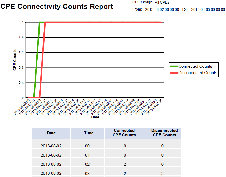
CPE Connectivity Count Report parameters:
· CPE Group—Statistics collection range: a CPE group or All CPEs.
· From To—Statistics collection time range.
The CPE Counts trend graph displays the changes of CPE connections and disconnections in a schedule.
CPE Connectivity Count Report fields:
· Date—Report date.
· Time—Report time. The sampling time interval is 1 hour.
· Connected CPE Counts—Total number of CPEs connected to the ACS in a schedule.
· Disconnected CPE Counts—Total number of CPEs disconnected from the ACS in a schedule.
CPE Connectivity Detail Report
A CPE connectivity detail report displays detailed CPE connectivity information about the specified CPEs in a schedule.
To add a CPE connectivity detail report, configure the following parameters:
· CPE Group—Click the Set
Parameter icon ![]() . The Set Parameter
page appears. Select a CPE group or All CPEs for statistics collection, and then
click OK.
. The Set Parameter
page appears. Select a CPE group or All CPEs for statistics collection, and then
click OK.
· Begin Time—Click the Set
Parameter icon ![]() . The Set Parameter
page appears. Select the report start time, and then click OK.
. The Set Parameter
page appears. Select the report start time, and then click OK.
· End Time—Click the Set
Parameter icon ![]() . The Set Parameter page appears. Select the report end time,
and then click OK.
. The Set Parameter page appears. Select the report end time,
and then click OK.
Figure 45 shows a CPE connectivity detail report.
Figure 45 CPE Connectivity Detail Report
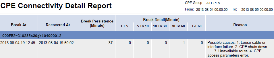
CPE Connectivity Detail Report parameters:
· CPE Group—Statistics collection range, a CPE group or All CPEs.
· From To—Statistics collection time range.
CPE Connectivity Detail Report fields:
· Break At—Time stamp when a break occurred.
· Recovered At—Time stamp when a break is recovered.
· Break Persistence (Minute)—Break duration, in minutes.
· Break Detail (Minute):
¡ LT 5—Number of breaks recovered in less than 5 minutes.
¡ 5 to 10—Number of breaks recovered in 5 to 10 minutes.
¡ 10 to 30—Number of breaks recovered in 10 to 30 minutes.
¡ 30 to 60—Number of breaks recovered in 30 to 60 minutes.
¡ GT 60—Number of breaks recovered in more than 60 minutes.
¡ Reason—Possible reason for the break.
CPE Connectivity Summary Report
A CPE connectivity summary report displays the summary of CPE connections in a schedule.
To add a CPE connectivity summary report, configure the following parameters:
· CPE Group—Click the Set
Parameter icon ![]() . The Set Parameter
page appears. Select a CPE group or All CPEs for statistics collection, and then
click OK.
. The Set Parameter
page appears. Select a CPE group or All CPEs for statistics collection, and then
click OK.
· Begin Time—Click the Set
Parameter icon ![]() . The Set Parameter
page appears. Select the report start time, and then click OK.
. The Set Parameter
page appears. Select the report start time, and then click OK.
· End Time—Click the Set
Parameter icon ![]() . The Set Parameter page appears. Select the report end time,
and then click OK.
. The Set Parameter page appears. Select the report end time,
and then click OK.
Figure 46 shows a CPE connectivity summary report.
Figure 46 CPE Connectivity Summary Report
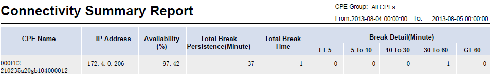
CPE Connectivity Summary Report parameters:
· CPE Group—Statistics collection range: a CPE group or All CPEs.
· From To—Statistics collection time range.
CPE Connectivity Summary Report fields:
· CPE Name—CPE names.
· IP Address—IP addresses of the CPEs.
· Availability (%)—Ratio of the time a CPE was connected to the ACS in a schedule.
· Total Break Persistence (Minute)—Total duration of all the breaks that occurred within the period of time, in minutes.
· Total Break Time—Total number of breaks that occurred within the period of time.
· Break Detail (Minute):
¡ LT 5—Number of breaks recovered in less than 5 minutes.
¡ 5 to 10—Number of breaks recovered in 5 to 10 minutes.
¡ 10 to 30—Number of breaks recovered in 10 to 30 minutes.
¡ 30 to 60—Number of breaks recovered in 30 to 60 minutes.
¡ GT 60—Number of breaks recovered in more than 60 minutes.
Device Flow Monthly Statistic Report
A device flow monthly statistic report displays total traffic statistics of mobile branch devices in a schedule.
To add a device flow monthly statistic report, configure the following parameters:
· Location—Click the Set
Parameter icon ![]() . The Set Parameter
page appears. Select a view or All
Devices for statistics collection, and then click OK.
. The Set Parameter
page appears. Select a view or All
Devices for statistics collection, and then click OK.
· End Time of Month—Click
the Set Parameter icon ![]() . The Set Parameter page appears. Select the report end time,
and then click OK.
. The Set Parameter page appears. Select the report end time,
and then click OK.
Figure 47 shows a device flow monthly statistic report.
Figure 47 Device Flow Monthly Statistic Report
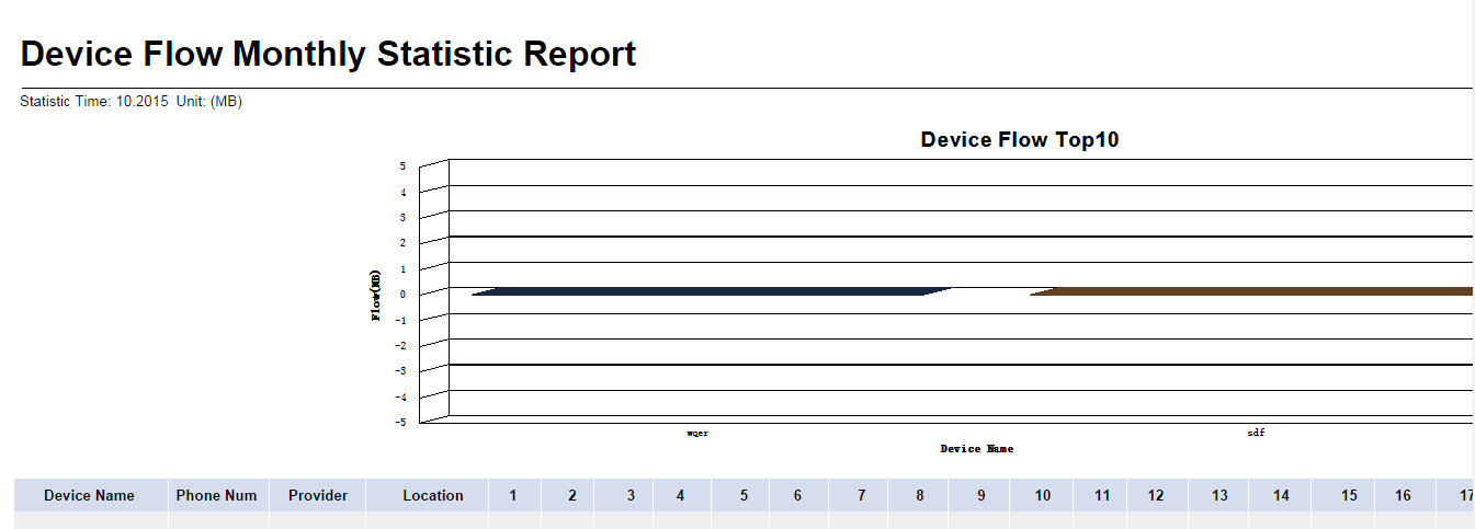
Device Flow Monthly Statistic Report parameters:
· Statistic Time—Statistics collection time range.
· Unit—Unit of the collected statistics, which is megabytes (MB).
The Device Flow Top10 chart displays the top 10 devices with the most total traffic in the specified time range.
Device Flow Monthly Statistic Report fields:
· Device Name—Name of the mobile branch device.
· Phone Num—Phone number of the SIM card on the mobile branch device.
· Provider—Service provider view of the SIM card on the mobile branch device.
· Location—Location view of the mobile branch device.
· 1 to 31—Daily traffic in the specified time range.
· Total Flow—Total traffic in the specified time range.
Device Flow Year Statistic Report
A device flow year statistic report displays total traffic statistics of mobile branch devices in a schedule.
To add a device flow year statistic report, configure the following parameters:
· Location—Click the Set
Parameter icon ![]() . The Set Parameter
page appears. Select a view or All
Devices for statistics collection, and then click OK.
. The Set Parameter
page appears. Select a view or All
Devices for statistics collection, and then click OK.
· Begin Time—Click the Set
Parameter icon ![]() . The Set Parameter
page appears. Select the report start time, and then click OK.
. The Set Parameter
page appears. Select the report start time, and then click OK.
· End Time—Click the Set
Parameter icon ![]() . The Set Parameter page appears. Select the report end time,
and then click OK.
. The Set Parameter page appears. Select the report end time,
and then click OK.
Figure 48 shows a device flow year statistic report.
Figure 48 Device Flow Year Statistic Report
Device Flow Year Statistic Report parameters:
· Statistic Time—Statistics collection time range.
· Unit—Unit of the collected statistics, which is megabytes (MB).
The Device Flow Top10 chart displays the top 10 devices with the most total traffic in the specified time range.
Device Flow Year Statistic Report fields:
· Device Name—Name of the mobile branch device.
· Phone Num—Phone number of the SIM card on the mobile branch device.
· Provider—Service provider view of the SIM card on the mobile branch device.
· Location—Location view of the mobile branch device.
· Jan~Dec—Monthly traffic in the specified time range.
· Total Flow—Total traffic in the specified time range.
Device Signal Strength Monthly Statistic Report
A device signal strength monthly statistic report displays signal strength statistics of mobile branch devices in a schedule.
To add a device signal strength monthly statistic report, configure the following parameters:
· Location—Click the Set
Parameter icon ![]() . The Set Parameter
page appears. Select a view or All
Devices for statistics collection, and then click OK.
. The Set Parameter
page appears. Select a view or All
Devices for statistics collection, and then click OK.
· End Time of Month—Click
the Set Parameter icon ![]() . The Set Parameter page appears. Select the report end time,
and then click OK.
. The Set Parameter page appears. Select the report end time,
and then click OK.
Figure 49 shows a device signal strength monthly statistic report.
Figure 49 Device Signal Strength Monthly Statistic Report
Device Signal Strength Monthly Statistic Report parameters:
· Statistic Time—Statistics collection time range.
· Unit—Unit of the collected statistics, which is dBm.
The worst Top10 RSSI of the Device chart displays the top 10 devices with the worst signal strength in the specified time range.
Device Signal Strength Monthly Statistic Report fields:
· Device Name—Name of the mobile branch device.
· Phone Num—Phone number of the SIM card on the mobile branch device.
· Provider—Service provider view of the SIM card on the mobile branch device.
· Location—Location view of the mobile branch device.
· 1 to 31—Average daily signal strength in the specified time range.
· Avg—Average signal strength in the specified time range.
Device Signal Strength Year Statistic Report
A device signal strength year statistic report displays signal strength statistics of mobile branch devices in a schedule.
To add a device signal strength year statistic report, configure the following parameters:
· Location—Click the Set
Parameter icon ![]() . The Set Parameter
page appears. Select a view or All
Devices for statistics collection, and then click OK.
. The Set Parameter
page appears. Select a view or All
Devices for statistics collection, and then click OK.
· Begin Time—Click the Set
Parameter icon ![]() . The Set Parameter
page appears. Select the report start time, and then click OK.
. The Set Parameter
page appears. Select the report start time, and then click OK.
· End Time—Click the Set
Parameter icon ![]() . The Set Parameter page appears. Select the report end time,
and then click OK.
. The Set Parameter page appears. Select the report end time,
and then click OK.
Figure 50 shows a device signal strength year statistic report.
Figure 50 Device Signal Strength Year Statistic Report

Device Signal Strength Year Statistic Report parameters:
· Statistic Time—Statistics collection time range.
· Unit—Unit of the collected statistics, which is dBm.
The worst Top10 RSSI of the Device chart displays the top 10 devices with the worst signal strength in the specified time range.
Device Signal Strength Year Statistic Report fields:
· Device Name—Name of the mobile branch device.
· Phone Num—Phone number of the SIM card on the mobile branch device.
· Provider—Service provider view of the SIM card on the mobile branch device.
· Location—Location view of the mobile branch device.
· Jan~Dec—Average monthly signal strength in the specified time range.
· Avg—Average signal strength in the specified time range.
Device Up Down Time Period Report
A device up down time period report displays online time, online duration, and offline time of mobile branch devices in a schedule.
To add a device up down time period report, configure the following parameters:
· Device—Click the Set
Parameter icon ![]() . The Set Parameter
page appears. Select a device for statistics collection, and then click OK.
. The Set Parameter
page appears. Select a device for statistics collection, and then click OK.
· Begin Time—Click the Set
Parameter icon ![]() . The Set Parameter
page appears. Select the report start time, and then click OK.
. The Set Parameter
page appears. Select the report start time, and then click OK.
· End Time—Click the Set
Parameter icon ![]() . The Set Parameter page appears. Select the report end time,
and then click OK.
. The Set Parameter page appears. Select the report end time,
and then click OK.
Figure 51 shows a device up down time period report.
Figure 51 Device Up Down Time Period Report
Device up down time period report parameters:
· Statistic Time—Statistics collection time range.
Device up down time period report fields:
· Device Name—Name of the mobile branch device.
· Phone Number—Phone number of the SIM card on the mobile branch device.
· Up Time—Time when the mobile branch device came online.
· Down Time—Time when the mobile branch device went offline.
· Time Period(Min)—Device online duration before the next offline.
Device Up Duration Monthly Statistic Report
A device up duration monthly statistic report displays online duration of mobile branch devices in a schedule.
To add a device up duration monthly statistic report, configure the following parameters:
· Location—Click the Set
Parameter icon ![]() . The Set Parameter
page appears. Select a view or All
Devices for statistics collection, and then click OK.
. The Set Parameter
page appears. Select a view or All
Devices for statistics collection, and then click OK.
· End Time of Month—Click
the Set Parameter icon ![]() . The Set Parameter page appears. Select the report end time,
and then click OK.
. The Set Parameter page appears. Select the report end time,
and then click OK.
Figure 52 shows a device up duration monthly statistic report.
Figure 52 Device Up Duration Monthly Statistic Report
Device Up Duration Monthly Statistic Report parameters:
· Statistic Time—Statistics collection time range.
· Unit—Unit of the collected statistics, which is hours.
The Device Up Duration Top10 chart displays the top 10 devices with the longest online duration in the specified time range.
Device Up Duration Monthly Statistic Report fields:
· Device Name—Name of the mobile branch device.
· Phone Num—Phone number of the SIM card on the mobile branch device.
· Provider—Service provider view of the SIM card on the mobile branch device.
· Location—Location view of the mobile branch device.
· 1 to 31—Daily device online duration in the specified time range.
· Total—Total device online duration in the specified time range.
Device Up Duration Year Statistic Report
A device up duration year statistic report displays online duration of mobile branch devices in a schedule.
To add a device up duration year statistic report, configure the following parameters:
· Location—Click the Set
Parameter icon ![]() . The Set Parameter
page appears. Select a view or All
Devices for statistics collection, and then click OK.
. The Set Parameter
page appears. Select a view or All
Devices for statistics collection, and then click OK.
· Begin Time—Click the Set
Parameter icon ![]() . The Set Parameter
page appears. Select the report start time, and then click OK.
. The Set Parameter
page appears. Select the report start time, and then click OK.
· End Time—Click the Set
Parameter icon ![]() . The Set Parameter page appears. Select the report end time,
and then click OK.
. The Set Parameter page appears. Select the report end time,
and then click OK.
Figure 53 shows a device up duration year statistic report.
Figure 53 Device Up Duration Year Statistic Report
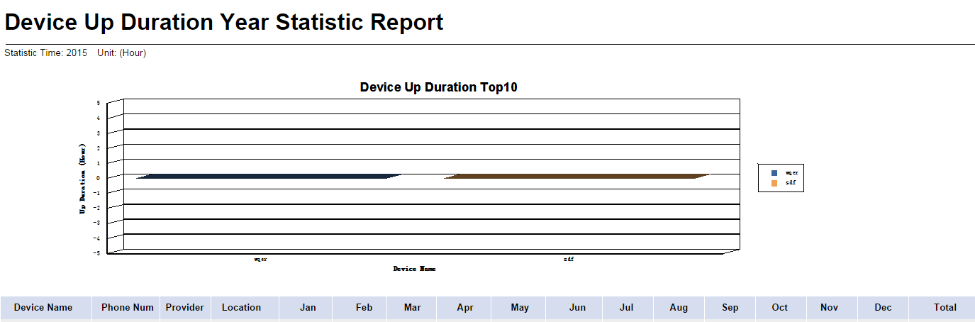
Device Up Duration Year Statistic Report parameters:
· Statistic Time—Statistics collection time range.
· Unit—Unit of the collected statistics, which is hours.
The Device Up Duration Top10 chart displays the top 10 devices with the longest online duration in the specified time range.
Device Up Duration Year Statistic Report fields:
· Device Name—Name of the mobile branch device.
· Phone Num—Phone number of the SIM card on the mobile branch device.
· Provider—Service provider view of the SIM card on the mobile branch device.
· Location—Location view of the mobile branch device.
· Jan~Dec—Monthly device online duration in the specified year.
· Total—Total device online duration in the specified year.
Device Up Statistic Report
A device up statistic report displays the online time, online duration, and signal strength of all mobile branch devices in a schedule.
To add a device up statistic report, configure the following parameters:
· Begin Time—Click the Set
Parameter icon ![]() . The Set Parameter
page appears. Select the report start time, and then click OK.
. The Set Parameter
page appears. Select the report start time, and then click OK.
· End Time—Click the Set
Parameter icon ![]() . The Set Parameter page appears. Select the report end time,
and then click OK.
. The Set Parameter page appears. Select the report end time,
and then click OK.
Figure 54 shows a device up statistic report.
Figure 54 Device Up Statistic Report

Device Up Statistic Report parameters:
· Statistic Time—Statistics collection time range.
The Device Up Times Location Top10 chart displays the top 10 devices with the longest online duration in the specified time range.
Device Up Statistic Report fields:
· Device Name—Name of the mobile branch device.
· Location—Location view of the mobile branch device.
· Up Times—Number of times that the mobile branch device comes online in the specified time range.
· Up Duration(Min)—Device online duration in the specified time range.
· Signal Strength(dBm)—Average device signal strength in the specified time range.
Inactive Device Statistic Report
An inactive device statistic report displays statistics about the top 10 devices with the shortest online duration in a schedule.
To add an inactive device statistic report, configure the following parameters:
· Begin Time—Click the Set
Parameter icon ![]() . The Set Parameter
page appears. Select the report start time, and then click OK.
. The Set Parameter
page appears. Select the report start time, and then click OK.
· End Time—Click the Set
Parameter icon ![]() . The Set Parameter page appears. Select the report end time,
and then click OK.
. The Set Parameter page appears. Select the report end time,
and then click OK.
Figure 55 shows a inactive device statistic report.
Figure 55 Inactive Device Statistic Report

Inactive Device Statistic Report parameters:
· Statistic Time—Statistics collection time range.
The Inactive Device Top10 chart displays the top 10 devices with the shortest online duration in the specified time range.
Inactive Device Statistic Report fields:
· Device Name—Name of the mobile branch device.
· Location—Location view of the mobile branch device.
· Up Duration(Min)—Device online duration in the specified time range.
· Last Up Time—The most recent time when the device came online in the specified time range.
One Device Flow Monthly Statistic Report
A one device flow monthly statistic report displays total traffic statistics of a mobile branch device in a schedule.
To add a one device flow monthly statistic report, configure the following parameters:
· Device—Click the Set
Parameter icon ![]() . The Set Parameter
page appears. Select a device for statistics collection, and then click OK.
. The Set Parameter
page appears. Select a device for statistics collection, and then click OK.
· End Time of Month—Click
the Set Parameter icon ![]() . The Set Parameter page appears. Select the report end time,
and then click OK.
. The Set Parameter page appears. Select the report end time,
and then click OK.
Figure 56 shows a one device flow monthly statistic report.
Figure 56 One Device Flow Monthly Statistic Report

One Device Flow Monthly Statistic Report parameters:
· Statistic Time—Statistics collection time range.
· Unit—Unit of the collected statistics, which is megabytes (MB).
One Device Flow Monthly Statistic Report fields:
· Device Name—Name of the mobile branch device.
· Phone Num—Phone number of the SIM card on the mobile branch device.
· Provider—Service provider view of the SIM card on the mobile branch device.
· Location—Location view of the mobile branch device.
· 1 to 31—Daily traffic in the specified time range.
· Total—Total traffic in the specified time range.
One Device Flow Year Statistic Report
A one device flow year statistic report displays total traffic statistics of a mobile branch device in a schedule.
To add a one device flow year statistic report, configure the following parameters:
· Device—Click the Set
Parameter icon ![]() . The Set Parameter
page appears. Select a device for statistics collection, and then click OK.
. The Set Parameter
page appears. Select a device for statistics collection, and then click OK.
· Begin Time—Click the Set Parameter icon ![]() . The Set Parameter
page appears. Select the report start time, and then click OK.
. The Set Parameter
page appears. Select the report start time, and then click OK.
· End Time—Click the Set
Parameter icon ![]() . The Set Parameter page appears. Select the report end time,
and then click OK.
. The Set Parameter page appears. Select the report end time,
and then click OK.
Figure 57 shows a one device flow year statistic report.
Figure 57 One Device Flow Year Statistic Report
![]()
One Device Flow Year Statistic Report parameters:
· Statistic Time—Statistics collection time range.
· Unit—Unit of the collected statistics, which is megabytes (MB).
One Device Flow Year Statistic Report fields:
· Device Name—Name of the mobile branch device.
· Phone Num—Phone number of the SIM card on the mobile branch device.
· Provider—Service provider view of the SIM card on the mobile branch device.
· Location—Location view of the mobile branch device.
· Jan~Dec—Monthly traffic in the specified time range.
· Total—Total traffic in the specified time range.
One Device Signal Strength Monthly Statistic Report
A one device signal strength monthly statistic report displays signal strength statistics of a mobile branch device in a schedule.
To add a one device signal strength monthly statistic report, configure the following parameters:
· Device—Click the Set
Parameter icon ![]() . The Set Parameter
page appears. Select a device for statistics collection, and then click OK.
. The Set Parameter
page appears. Select a device for statistics collection, and then click OK.
· End Time of Month—Click
the Set Parameter icon ![]() . The Set Parameter page appears. Select the report end time,
and then click OK.
. The Set Parameter page appears. Select the report end time,
and then click OK.
Figure 58 shows a one device signal strength monthly statistic report.
Figure 58 One Device Signal Strength Monthly Statistic Report
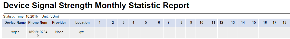
One Device Signal Strength Monthly Statistic Report parameters:
· Statistic Time—Statistics collection time range.
· Unit—Unit of the collected statistics, which is dBm.
One Device Signal Strength Monthly Statistic Report fields:
· Device Name—Name of the mobile branch device.
· Phone Num—Phone number of the SIM card on the mobile branch device.
· Provider—Service provider view of the SIM card on the mobile branch device.
· Location—Location view of the mobile branch device.
· 1 to 31—Average daily signal strength in the specified time range.
· Avg—Average signal strength in the specified time range.
One Device Signal Strength Year Statistic Report
A one device signal strength year statistic report displays signal strength statistics of a mobile branch device in a schedule.
To add a one device signal strength monthly statistic report, configure the following parameters:
· Device—Click the Set
Parameter icon ![]() . The Set Parameter
page appears. Select a device for statistics collection, and then click OK.
. The Set Parameter
page appears. Select a device for statistics collection, and then click OK.
· Begin Time—Click the Set
Parameter icon ![]() . The Set Parameter
page appears. Select the report start time, and then click OK.
. The Set Parameter
page appears. Select the report start time, and then click OK.
· End Time—Click the Set
Parameter icon ![]() . The Set Parameter page appears. Select the report end time,
and then click OK.
. The Set Parameter page appears. Select the report end time,
and then click OK.
Figure 59 shows a one device signal strength year statistic report.
Figure 59 One Device Signal Strength Year Statistic Report
![]()
One Device Signal Strength Year Statistic Report parameters:
· Statistic Time—Statistics collection time range.
· Unit—Unit of the collected statistics, which is dBm.
One Device Signal Strength Year Statistic Report fields:
· Device Name—Name of the mobile branch device.
· Phone Num—Phone number of the SIM card on the mobile branch device.
· Provider—Service provider view of the SIM card on the mobile branch device.
· Location—Location view of the mobile branch device.
· Jan~Dec—Average monthly signal strength in the specified time range.
· Average—Average signal strength in the specified time range.
One Device Up Duration Monthly Statistic Report
A one device up duration monthly statistic report displays online duration of a mobile branch device in a schedule.
To add a one device up duration monthly statistic report, configure the following parameters:
· Device—Click the Set
Parameter icon ![]() . The Set Parameter
page appears. Select a device for statistics collection, and then click OK.
. The Set Parameter
page appears. Select a device for statistics collection, and then click OK.
· End Time of Month—Click
the Set Parameter icon ![]() . The Set Parameter page appears. Select the report end time,
and then click OK.
. The Set Parameter page appears. Select the report end time,
and then click OK.
Figure 60 shows a one device up duration monthly statistic report.
Figure 60 One Device Up Duration Monthly Statistic Report

One Device Up Duration Monthly Statistic Report parameters:
· Statistic Time—Statistics collection time range.
· Unit—Unit of the collected statistics, which is hours.
Device Up Duration Monthly Statistic Report fields:
· Device Name—Name of the mobile branch device.
· Phone Num—Phone number of the SIM card on the mobile branch device.
· Provider—Service provider view of the SIM card on the mobile branch device.
· Location—Location view of the mobile branch device.
· 1 to 31—Daily device online duration in the specified time range.
· Total—Total device online duration in the specified time range.
One Device Up Duration Year Statistic Report
A one device up duration year statistic report displays online duration of a mobile branch device in a schedule.
To add a one device up duration year statistic report, configure the following parameters:
· Device—Click the Set
Parameter icon ![]() . The Set Parameter
page appears. Select a device for statistics collection, and then click OK.
. The Set Parameter
page appears. Select a device for statistics collection, and then click OK.
· Begin Time—Click the Set
Parameter icon ![]() . The Set Parameter
page appears. Select the report start time, and then click OK.
. The Set Parameter
page appears. Select the report start time, and then click OK.
· End Time—Click the Set
Parameter icon ![]() . The Set Parameter page appears. Select the report end time,
and then click OK.
. The Set Parameter page appears. Select the report end time,
and then click OK.
Figure 61 shows a one device up duration year statistic report.
Figure 61 One Device Up Duration Year Statistic Report

One Device Up Duration Year Statistic Report parameters:
· Statistic Time—Statistics collection time range.
· Unit—Unit of the collected statistics, which is hours.
One Device Up Duration Year Statistic Report fields:
· Device Name—Name of the mobile branch device.
· Phone Num—Phone number of the SIM card on the mobile branch device.
· Provider—Service provider view of the SIM card on the mobile branch device.
· Location—Location view of the mobile branch device.
· Jan~Dec—Monthly device online duration in the specified time range.
· Total—Total device online duration in the specified time range.
Phone Flow Statistic Report
A phone flow statistic report displays the sent traffic, received traffic, and total traffic of SIM cards on mobile branch device in a schedule.
To add a phone flow statistic report, configure the following parameters:
· Provider—Click the Set
Parameter icon ![]() . The Set Parameter
page appears. Select a service provider view or All SIM Cards for
statistics collection, and then click OK.
. The Set Parameter
page appears. Select a service provider view or All SIM Cards for
statistics collection, and then click OK.
· Location—Click the Set
Parameter icon ![]() . The Set Parameter
page appears. Select a location view or All Devices for statistics collection,
and then click OK.
. The Set Parameter
page appears. Select a location view or All Devices for statistics collection,
and then click OK.
· Begin Time—Click the Set
Parameter icon ![]() . The Set Parameter
page appears. Select the report start time, and then click OK.
. The Set Parameter
page appears. Select the report start time, and then click OK.
· End Time—Click the Set
Parameter icon ![]() . The Set Parameter page appears. Select the report end time,
and then click OK.
. The Set Parameter page appears. Select the report end time,
and then click OK.
Figure 62 shows a phone flow statistic report.
Figure 62 Phone Flow Statistic Report
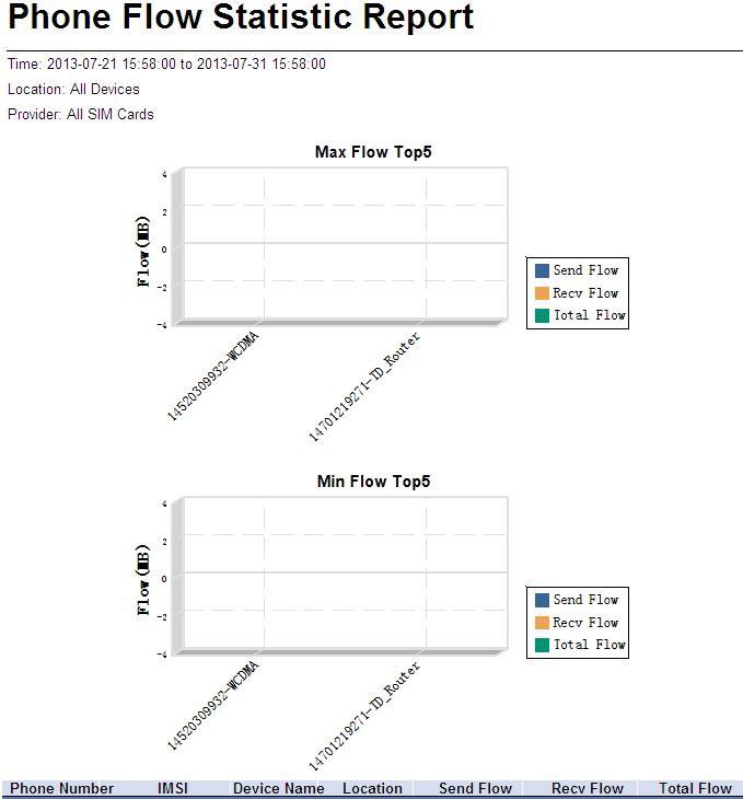
Phone Flow Statistic Report parameters:
· Time—Statistics collection time range.
· Location—Statistics collection location range: All Devices or a location view.
· Provider—Statistics collection range: All SIM Cards or a service provider view.
The Max Flow Top5 chart displays the top five SIM cards with the most total traffic in a schedule. The sent traffic, received traffic, and total traffic of the top five SIM cards in the schedule are also shown in the chart.
The Min Flow Top5 chart shows top the five SIM cards with the least total traffic in a schedule. The sent traffic, received traffic, and total traffic of the top five SIM cards in the schedule are also shown in the chart.
Phone Flow Statistic Report fields:
· Phone Number—Phone number of the SIM card on the mobile branch device.
· IMSI—IMSI number of the SIM card on the mobile branch device.
· Device Name—Name of the mobile branch device to which the SIM card belongs.
· Location—Location view of the mobile branch device to which the SIM card belongs.
· Send Flow—Sent traffic of the SIM card in a schedule.
· Recv Flow—Received traffic of the SIM card in a schedule.
· Total Flow—Sent traffic and received traffic of the SIM card in a schedule.
Phone Inventory Report
A phone inventory report displays information about SIM cards managed by MBM, location distribution, and provider distribution in a schedule.
To add a phone inventory report, configure the following parameters:
· Location—Click the Set
Parameter icon ![]() . The Set Parameter
page appears. Select a location view or All Devices for statistics collection,
and then click OK.
. The Set Parameter
page appears. Select a location view or All Devices for statistics collection,
and then click OK.
· Provider—Click the Set
Parameter icon ![]() . The Set Parameter
page appears. Select a service provider view or All SIM Cards for
statistics collection, and then click OK.
. The Set Parameter
page appears. Select a service provider view or All SIM Cards for
statistics collection, and then click OK.
Figure 63 shows a phone inventory report.
Figure 63 Phone Inventory Report
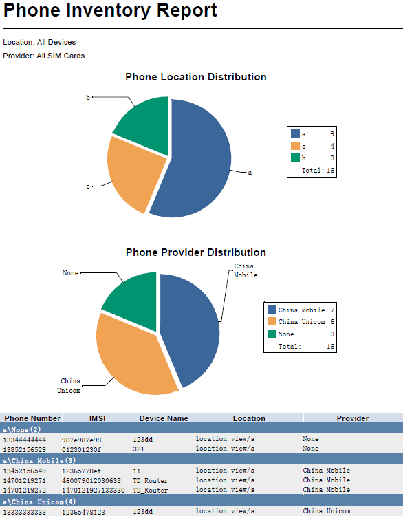
Phone Inventory Report parameters:
· Location—Statistics collection location range: All Devices or a location view.
· Provider—Statistics collection range: All SIM Cards or a service provider view.
Based on the location view, the Phone Location Distribution pie chart displays the location distribution of SIM cards in the specified location range.
Based on the service provider view, the Phone Provider Distribution pie chart displays the provider distribution of SIM cards in the specified location range.
Phone Inventory Report fields:
· Phone Number—Phone number of the SIM card on the mobile branch device.
· IMSI—IMSI number of the SIM card on the mobile branch device.
· Device Name—Name of the mobile branch device to which the SIM card belongs.
· Location—Location view of the mobile branch device to which the SIM card belongs.
· Provider—Service provider view of the SIM card.
· Location View\Service Provider View(n)—There are n SIM cards that belong to the service provider view in the location view, where n refers to the number of SIM cards.
Phone Rate Statistic Report
A phone rate statistic report displays the sending rate, receiving rate, and total rate of SIM cards on mobile branch devices in a schedule.
To add a phone rate statistic report, configure the following parameters:
· Provider—Click the Set
Parameter icon ![]() . The Set Parameter
page appears. Select a service provider view or All SIM Cards for
statistics collection, and then click OK.
. The Set Parameter
page appears. Select a service provider view or All SIM Cards for
statistics collection, and then click OK.
· Location—Click the Set
Parameter icon ![]() . The Set Parameter
page appears. Select a location view or All Devices for statistics collection,
and then click OK.
. The Set Parameter
page appears. Select a location view or All Devices for statistics collection,
and then click OK.
· Begin Time—Click the Set
Parameter icon ![]() . The Set Parameter
page appears. Select the report start time, and then click OK.
. The Set Parameter
page appears. Select the report start time, and then click OK.
· End Time—Click the Set
Parameter icon ![]() . The Set Parameter page appears. Select the report end time,
and then click OK.
. The Set Parameter page appears. Select the report end time,
and then click OK.
Figure 64 shows a phone rate statistic report.
Figure 64 Phone Rate Statistic Report
Phone Rate Statistic Report parameters:
· Time— Statistics collection time range.
· Location—Statistics collection location range: All Devices or a location view.
· Provider—Statistics collection range: All SIM Cards or a service provider view.
The Max Rate Top5 chart shows the top five SIM cards with the highest rate in a schedule. The sending rate, receiving rate, and total rate of the top five SIM cards in the schedule are also shown in the chart.
The Min Rate Top5 chart shows the top five SIM cards with the lowest rate in a schedule. The sending rate, receiving rate, and total rate of the top five SIM cards in the schedule are also shown in the chart.
Phone Rate Statistic Report fields:
· Phone Number—Phone number of the SIM card on the mobile branch device.
· IMSI—IMSI number of the SIM card on the mobile branch device.
· Device Name—Name of the mobile branch device to which the SIM card belongs.
· Location—Location view of the mobile branch device to which the SIM card belongs.
· Send Rate—Sending rate of the SIM card in a schedule.
· Recv Rate—Receiving rate of the SIM card in a schedule.
· Total Rate—Sending rate and receiving rate of the SIM card in a schedule.
Phone Signal Strength Detail Report
A phone signal strength detail report displays the signal strength details of a SIM card on a mobile branch device in a schedule.
To add a phone signal strength detail report, configure the following parameters:
· Phone Number—Click the Set
Parameter icon ![]() . The Set Parameter
page appears. Select a SIM card number to be measured
from the Phone Number list in the Device-Phone
Number format.
. The Set Parameter
page appears. Select a SIM card number to be measured
from the Phone Number list in the Device-Phone
Number format.
· Begin Time—Click the Set
Parameter icon ![]() . The Set Parameter
page appears. Select the report start time, and then click OK.
. The Set Parameter
page appears. Select the report start time, and then click OK.
· End Time—Click the Set
Parameter icon ![]() . The Set Parameter page appears. Select the report end time,
and then click OK.
. The Set Parameter page appears. Select the report end time,
and then click OK.
Figure 65 shows a phone signal strength detail report.
Figure 65 Phone Signal Strength Detail Report

Phone Signal Strength Detail Report parameters:
· Time—Statistics collection time range.
· Device- Phone Number—Device name and SIM card number used for data collection.
The Signal Strength Trend chart displays the signal strength change of a SIM card on a mobile branch device in a schedule.
Phone Signal Strength Detail Report fields:
· Phone Number—Phone number of the SIM card on the mobile branch device.
· IMSI—IMSI number of the SIM card on the mobile branch device.
· Device Name—Name of the mobile branch device to which the SIM card belongs.
· Signal Strength—Signal strength of the SIM card.
· Time—Data collection interval. The default data collection interval is 1 hour.
Phone Signal Strength Summary Report
A phone signal strength summary report displays signal strength statistics of SIM cards on mobile branch devices in a schedule.
To view a phone signal strength summary report, configure the following parameters:
· Provider—Click the Set
Parameter icon ![]() . The Set Parameter
page appears. Select a service provider view or All SIM Cards for
statistics collection, and then click OK.
. The Set Parameter
page appears. Select a service provider view or All SIM Cards for
statistics collection, and then click OK.
· Location—Click the Set
Parameter icon ![]() . The Set Parameter
page appears. Select a location view or All Devices for statistics collection,
and then click OK.
. The Set Parameter
page appears. Select a location view or All Devices for statistics collection,
and then click OK.
· Begin Time—Click the Set
Parameter icon ![]() . The Set Parameter
page appears. Select the report start time, and then click OK.
. The Set Parameter
page appears. Select the report start time, and then click OK.
· End Time—Click the Set
Parameter icon ![]() . The Set Parameter page appears. Select the report end time,
and then click OK.
. The Set Parameter page appears. Select the report end time,
and then click OK.
Figure 66 shows a phone signal strength summary report.
Figure 66 Phone Signal Strength Summary Report

Phone Signal Strength Summary Report parameters:
· Time—Statistics collection time range.
· Location—Statistics collection location range: All Devices or a location view.
· Provider—Statistics collection range: All SIM Cards or a service provider view.
The Signal Strength Distribute chart displays the distribution of signal strength levels (No Signal, Poor, Low, Moderate, Good, and Excellent) of SIM cards on mobile branch devices.
Phone Signal Strength Summary Report fields:
· Phone Number—Phone number of the SIM card on the mobile branch device.
· IMSI—IMSI number of the SIM card on the mobile branch device.
· Device Name—Name of the mobile branch device to which the SIM card belongs.
· Location—Location view of the mobile branch device to which the SIM card belongs.
· Signal Strength—Signal strength level, including No Signal, Poor, Low, Moderate, Good, and Excellent.
· Location View\Service Provider View(n)—There are n SIM cards that belongs to the service provider view in the location view, where n refers to the number of SIM cards.
Typical BIMS applications
The following scenarios are provided to help you better understand how BIMS is typically applied to aid in network management.
Prerequisites of BIMS applications
Before starting any BIMS procedures in the following scenarios, make sure you have:
· Installed and configured the IMC base platform and BIMS service components. The IMC platform works as your network management system.
· Established administrator access to the IMC base platform.
· Verified that the CPEs to be deployed and managed by BIMS support the TR-069 protocol.
Example 1: Deploying CPE configurations in a data center through a BIMS zero-configuration deployment solution
Scenario description
As a data center network administrator, you must manage a large number of access switches supporting the CWMP protocol, and other complicated services. You use IMC BIMS to centrally manage and deploy various types of these CPE devices. To unify your access CPE device management, you deploy similar device models with the same startup configurations.
Next, you are assigned to perform a network expansion plan, which requires adding a batch of CPE devices. These CPEs are the same model—HP 5820, and act as the same level access devices. You use the BIMS zero-configuration CPE deployment solution to automatically deploy a startup configuration file to the CPE devices, greatly increasing your efficiency and reducing your workload.
The network topology of the CPE devices for this example is shown in Figure 67.
Figure 67 Network topology of CPE devices—Example 1
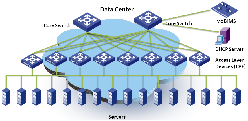
|
|
NOTE: The zero-configuration solution enables you to configure and deploy CPEs from the IMC BIMS client without performing any operations on the CPE devices. |
Task analysis
To execute this scenario, perform the following tasks:
1. Add virtual CPEs to BIMS.
To add a CPE to BIMS, you must first add a CPE record to the CPE List, which contains the serial ID and OUI of the CPE. Any CPE listed in the CPE List, but has never accessed BIMS is called a virtual CPE.
In this example, since the target CPEs belong to the same vendor—HP, you can use the quick adding function, which enables you to scan the CPE serial IDs with a barcode scanner.
2. Customize a startup configuration file for the target CPEs.
3. Create an automatic deployment task for deploying the configuration file on the target CPEs automatically.
The zero-configuration CPE deployment solution process is shown in Figure 68.
Figure 68 Zero-configuration CPE solution process
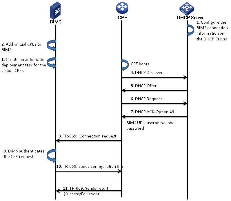
|
|
NOTE: As a best practice to use the zero-configuration CPE deployment solution, configure the DHCP server in the data center server, which informs the CPEs of the BIMS connection information. |
Process description
The following steps describe the process shown in Figure 68.
1. Configure BIMS connection information, such as the BIMS URL, the connection user name, and password, on the DHCP Server.
2. Add virtual CPEs to BIMS.
Add a CPE record containing the CPE name, serial ID, OUI, and related information to the CPE List of BIMS.
3. Customize a startup configuration file, and create an automatic deployment task for the virtual CPEs.
4. The target CPE boots and sends a DHCP discover packet.
5. The DHCP server replies with an Offer.
6. The CPE sends a DHCP request to the DHCP server.
7. The DHCP server replies with an ACK-Option 43, which contains the BIMS URL, connection username, and password.
8. The CPE sends a TR-069 connection request to BIMS.
9. BIMS authenticates the request.
After a virtual CPE passes the authentication, it becomes an available CPE that can be managed by BIMS practically.
10. When the CPE passes the authentication, BIMS sends the configuration file to the CPE.
11. CPE applies the configuration file, and sends the operation event (Success or Fail) to BIMS.
BIMS operations
The following sections describe the operations you must perform in BIMS for this example.
Quickly adding virtual CPEs to BIMS
In this example, the CPEs to be added are the same model—HP 5820, so they have the same OUI. You can use a barcode scanner to scan the bar codes on the device packages to quickly add the virtual CPEs.
To quickly add virtual CPEs to BIMS:
1. Log on to BIMS as administrator.
2. Click Service > BIMS > Resource Management > Add CPE.
3. On the Add CPE page, click Quickly Add CPE.
4. On the Quickly Add CPE page, specify the basic information of a target CPE, including Serial ID, OUI, CPE Name, CPE Model, and CPE Group.
5. Click OK.
The CPE HP5820–V1 is added to BIMS as a virtual CPE. At the same time, BIMS clears the Serial ID and CPE Name fields, reserves other CPE values, and then automatically places the cursor over the Serial ID text box on the page.
6. To add the next virtual CPE, place your cursor over the Serial ID text box, use a barcode scanner to scan the serial ID of the second CPE, enter the CPE name as needed, and then click OK.
|
|
NOTE: You can specify a name for each virtual CPE. Or, you can leave the CPE Name field blank, and then BIMS automatically sets the CPE name as the serial ID of the CPE. |
7. Repeat this procedure to add remaining CPEs to BIMS.
For more information, see "Quickly adding CPEs."
Customizing a startup configuration file for the target CPEs
This example requires you to customize a startup configuration file for all the HP5820 CPEs that will access the data center network. In BIMS, all configuration files or segments are generated by creating a configuration template operation.
To create a configuration template:
1. Click Service > BIMS > Configuration Management > Config Templates.
The Config Templates list appears.
2. Navigate to the folder to which you want to add the configuration template. You can create a folder for storing the new configuration templates.
For more information, see "Creating a configuration template."
3. Click Add, and then specify parameters for the configuration template:
a. Specify a Name for the configuration template, such as hp5820_startup_configuration.cfg.
b. Set the Template Type to Configuration File.
c. Click Select Model, and then select the class HP 5820x.
4. Enter the contents of your configuration template in the Content field.
5. Click OK.
The configuration template appears in the template folder.
For more information, see "Creating a configuration template."
Creating an automatic deployment task
1. Click Service > BIMS > Configuration Management > Deployment Guide.
2. On the Deployment Guide
page, click the By CPE icon ![]() in the Auto Deploy Configuration field.
in the Auto Deploy Configuration field.
3. Select the startup configuration folder, and then select the configuration template.
4. Select Startup Configuration from the File Type to be Deployed list box.
5. Click Select CPE, select the virtual CPEs added in previous procedure, and then click OK.
The selected CPE appears in the CPE-to-Deploy list.
6. Click Next.
7. If the configuration file contains variables, set values for the variables, and then click Next.
8. BIMS sets the task name by default. You can specify a name for the automatic deployment task as needed.
9. Enter a description for the task, and then click Finish.
The automatic deployment task is created. When a target CPE accesses the data center network for the first time and passes the BIMS authentication, BIMS immediately executes this task to deploy the file to the target CPE. After the target CPE receives the configuration file as its startup configuration, the CPE shuts down and starts up with the startup configuration.
For more information, see "Automatically deploying CPE configurations."
Example 2: Deploying CPE configurations through a USB flash drive
Scenario description
A company has several branches located in different areas. The branches communicate with the headquarters over the Internet through access devices that support CWMP. Deploy CPEs (MSR 30-20 in this example) at the branches, and use IMC BIMS at the headquarters to centrally manage them. Branch hosts access the Internet through the CPEs, as shown in Figure 69.
Figure 69 Network topology—Example 2
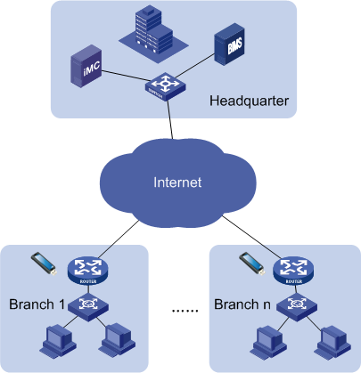
Task analysis
To execute this scenario, the network administrator at the headquarters performs the following tasks:
1. Adds virtual CPEs to BIMS.
2. Imports software to be deployed to the branch CPEs to BIMS.
3. Creates an automatic deployment task, and bind the CPE software to the virtual CPEs.
4. Creates configuration files on USB flash drives, and distribute the USB flash drives to branch network administrators.
After obtaining a USB flash drive, a branch network administrator performs the following tasks:
1. Specifies the user name and password for accessing the Internet in the configuration file on the USB flash drive, and renames and saves the file to a computer.
2. Copies the new file to the root of the USB flash drive.
3. Plugs the USB flash drive into a CPE, and then powers on the CPE.
The CPE then automatically accesses BIMS, and installs the CPE software.
BIMS operations
The following sections describe the operations you must perform in BIMS for this example.
Adding virtual CPEs to BIMS
When you add virtual CPEs, choose the ACS Username authentication type. Configure only one ACS username for the CPE at each branch.
To add virtual CPEs to BIMS:
1. Click Service > BIMS > Resource Management > Add CPE.
2. On the Add CPE page, specify the following parameters:
Basic information
¡ Authentication Type—Select ACS UserName.
¡ CPE Name—Enter the CPE name.
¡ ACS URL—Enter the ACS URL.
¡ ACS Username—Enter the ACS username for the CPE. The user name must be unique in BIMS.
¡ ACS Password Generated—Select Automatically Generated.
¡ CPE Model—Select MSR 30-20.
¡ CPE Group—Select a CPE group. This item is available only when you have added a CPE group.
3. Click OK.
The CPE that you add appears in the CPE List.
4. Repeat this procedure to add the remaining virtual CPEs to BIMS.
Importing CPE software to BIMS
1. Click Service > BIMS > Configuration Management > Software Library.
All CPE software is displayed in the Software List.
2. Click Import.
3. On the Import CPE Software page, click Source File to the right of the Source File field, and then click Browse.
4. In the Choose File to Upload dialog box, select the target software in your computer, and then click Open.
The full path and name of the file you selected appears in the Source File field.
5. Confirm the file you want to upload, and then click OK.
The software file name appears in the Source File and Target File fields.
6. Modify the content of the Target File field to MSR 30-20, which appears as Software Name in the Software List.
7. Enter the version of the software to be imported.
8. Select the type of CPEs where the CPE software you import can be deployed:
a. Click Select Model to the right of the Applicable CPEs field.
b. Enter MSR 30-20 in the Model Name field and click Query.
c. Select the box for MSR 30-20 in the Model List, and then click OK.
The class you select appears in the Applicable CPE list.
9. Enter a description for the software to be imported.
10. Click OK.
The imported software appears in the Software List.
Creating an automatic deployment task
This task binds the imported CPE software to the virtual CPEs, and enables BIMS to automatically deploy the CPE software to the virtual CPEs after they access BIMS for the first time.
To create an automatic deployment task by CPE model:
1. Click Service > BIMS > Configuration Management > Deployment Guide.
The Deployment Guide page appears.
2. Click the By CPE Model icon ![]() in the Auto Deploy Software field.
in the Auto Deploy Software field.
The Auto Deploy Software page appears.
3. Click Select, and then select the software to be deployed.
4. Set the following attributes to specify how the task is executed:
¡ Task Name—Enter a task name. By default, the task name is task + current time.
¡ Description—Enter the task description.
5. Click Select Model.
6. Enter MSR 30-20 in the Model Name field, and click Query.
7. Select the box for MSR 30-20 in the Model List, and then click OK.
If a virtual CPE that belongs to the class you specify accesses BIMS for the first time, the system automatically deploys the corresponding software to the CPE.
8. Click OK.
Creating a USB configuration template
1. Click Service > BIMS > Configuration Management > Configuration Templates.
The Configuration Templates list appears.
2. Click Add.
The Add Configuration Template page appears.
3. Specify the following information:
¡ Name—Enter udisk_zero_pppoe.cfg.
¡ Template Type—Select Segment.
¡ Segment Type—Select Console.
¡ Folder—Select RootFolder.
¡ Applicable CPEs—Click Select Model. Enter MSR 30-20 in the Model Name field and click Query. Select the box for MSR 30-20 in the Model List, and then click OK.
¡ Description—Enter a description for the configuration template.
¡ Content—Enter the configuration file content in the Content field. For example:
#This is for spoke to connect internet by PPPoE.
interface Dialer1
link-protocol ppp
dialer user USERNAME
ppp pap local-user USERNAME password simple PASSWORD
ip address ppp-negotiate
dialer-group 1
dialer bundle 1
interface Ethernet0/0
port link-mode route
pppoe-client dial-bundle-number 1
dialer-rule 1 ip permit
ip route-static 0.0.0.0 0.0.0.0 Dialer1
#This is to enable dynamic domain name resolution.
dns resolve
dns server 100.100.50.11
#This is for spoke to access ACS/BIMS.
cwmp
cwmp acs url http://bims.h3c.com:9090
cwmp acs username $${ACS_USERNAME}
cwmp acs password simple $${ACS_PASSWORD}
cwmp cpe inform interval enable
#This is to enable http, so spoke can be accessed by web.
ip http enable
4. Click OK.
The configuration template you created appears in the selected template folder.
Exporting a USB boot file
1. Click Service > BIMS > Configuration Management > Configuration Templates.
The configuration templates and folders stored at the template folder root level are displayed in the Configuration Templates list.
2. Select udisk_zero_pppoe.cfg, and then click Export USB boot files.
The Select Configuration Template area displays the path and name of the selected file.
3. Click Select CPE.
4. On the CPE List dialog box, specify the query criteria, and then click Query.
The CPE List displays all virtual CPEs that match the query criteria.
5. Select the target CPEs from the CPE List, and then click OK.
The Export USB boot files page displays the selected CPEs.
6. Click OK.
7. On the Download USB boot files page, click USB boot files and download the USB boot file to the root directory of a USB flash drive.
The following is a USB boot file example:
#This is for spoke to connect internet by PPPoE.
interface Dialer1
link-protocol ppp
dialer user USERNAME
ppp pap local-user USERNAME password simple PASSWORD
ip address ppp-negotiate
dialer-group 1
dialer bundle 1
interface Ethernet0/0
port link-mode route
pppoe-client dial-bundle-number 1
dialer-rule 1 ip permit
ip route-static 0.0.0.0 0.0.0.0 Dialer1
#This is to enable dynamic domain name resolution.
dns resolve
dns server 100.100.50.11
#This is for spoke to access ACS/BIMS.
cwmp
cwmp acs url http://bims.h3c.com:9090
cwmp acs username rt1
cwmp acs password simple 5WVZIvg
cwmp cpe inform interval enable
#This is to enable http, so spoke can be accessed by web.
ip http enable
8. Rename the exported file to xxx. autodeploy.cfg, and distribute the USB flash drive to a branch network administrator.
For example, rename the file Router1.cfg to Router1.autodeploy.cfg for branch 1 and rename the file Router2.cfg to Router2.autodeploy.cfg for branch 2.
Booting a CPE from a USB flash drive
This task is for a branch network administrator to perform:
1. Specify the user name and password for accessing the Internet in the configuration file on the USB flash drive, and then rename and save the file to a computer.
2. Copy the new file to the root directory of the USB flash drive.
3. Plug the USB flash drive into a CPE, and then power on the CPE.
The CPE boots from the USB flash drive, loads the configurations, and automatically accesses BIMS. When identifying the state of the CPE as online, BIMS automatically deploys the CPE software to the CPE.
Example 3: Deploying CPEs in branch offices
Scenario description
As a network administrator working at company headquarters, you must manage all CPEs, including those located at different branches. You are assigned to:
· Upgrade the current software version of all CPEs whose class is MSR20–10 to the latest version—V1.5.
· Deploy the latest CPE software version (V1.5) to an MSR20–10 CPE the first time it accesses the company network.
The network topology of the CPE devices for this example is shown in Figure 70.
Figure 70 Network topology of CPE devices—Example 2
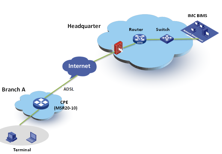
Task analysis
To execute this scenario, perform the following tasks:
1. Configure BIMS information on the CPE devices.
2. Import the new software version to BIMS.
3. Create a software deployment task for upgrading the software on the MSR20–10 CPEs managed by BIMS.
4. Create an automatic software deployment task to deploy the new version of software to the newly-added MSR20–10 CPEs.
The process of automatically deploying a CPE through BIMS is shown in Figure 71.
Figure 71 Automatically deploying a CPE
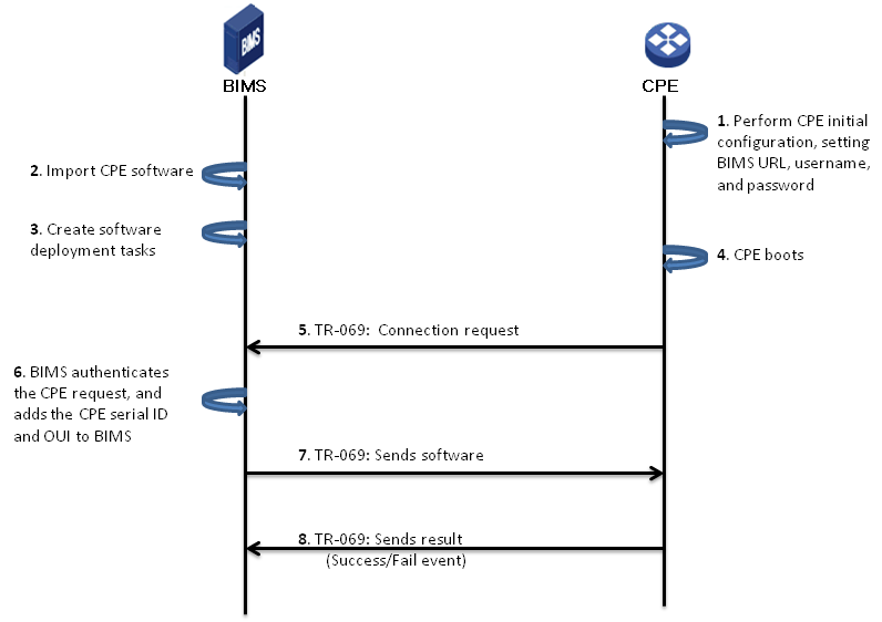
Process description
The following steps describe the process shown in Figure 71.
1. Plan and configure BIMS authentication users for each branch, and then inform the administrators in each branch of the BIMS URL, connection username, and password. The administrators in the branches perform CPE initial configurations on the CPE devices, including setting the BIMS URL and connection information.
|
|
NOTE: Connection usernames and passwords configured on the CPE devices must match those configured in BIMS. Otherwise, the CPEs cannot pass the BIMS authentication. |
2. Import the latest CPE software (V1.5) to BIMS.
3. Create software deployment tasks for deploying the MSR20–10 CPEs.
4. An MSR20–10 CPE boots.
5. The CPE sends a TR-069 connection request to BIMS.
6. BIMS authenticates the request, checking whether the user name and password in the request match those configured for BIMS authentication users or the common password parameter.
7. After the CPE passes the authentication, BIMS sends the software to the CPE.
8. The CPE applies the software, and sends the operation event (Success or Fail) to BIMS.
BIMS operations
The following sections describe the operations you must perform in BIMS for this example.
Configuring BIMS information on CPEs
For those MSR20–10 CPEs that will be added to the network, you must configure the BIMS URL, connection username, and password on those devices.
To configure BIMS information on a CPE:
1. Log on to an MSR20–10 device that will be added to the network.
2. Configure the BIMS URL, connection username, and password, as shown in Figure 72.
Figure 72 Initial configuration command lines
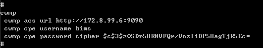
|
|
NOTE: The commands vary depending on the device type. For more information, see the user guide for the corresponding device. |
Importing CPE software to BIMS
This task imports the latest CPE software version (V1.5) saved on the local client in BIMS.
To import the CPE software:
1. Click Service > BIMS > Configuration Management > Software Library.
The Software List appears.
2. Click Import....
3. On the Import CPE Software page, click the Source File to the right of the Source File field, and then click Browse....
4. On the Choose File to Upload dialog box, select the software file, and then click Open.
The full path and name of the selected file appears in the Source File field.
5. Click OK.
The software file appears in both the Source File and Target File fields.
6. Set the Software Version as V1.5.
7. Click Select Model, select the CPE class HP MSR20–10 from the Model List, and then click OK.
8. Enter a brief description of the software, and then click OK. For more information, see "Deploying CPE software."
Creating a software deployment task
This task upgrades the software on the HP MSR20–10 CPEs currently managed by BIMS.
To create an automatic software deployment task:
1. Click Service > BIMS > Configuration Management > Deployment Guide.
2. On the Deployment Guide
page, click the Deploy Software icon![]() .
.
3. On the Deploy Software page, select the software file in the CPE Software field.
4. Schedule a time to execute the task.
For example, to deploy the software to
all HP MSR20–10 devices at 23:00:00 on January 20, 2013, select Scheduled in the
Operation Time field, click the Calendar icon![]() , and then set the data and time to 2013-01-20 23:00:00.
, and then set the data and time to 2013-01-20 23:00:00.
5. Enter a brief description for the task.
6. Click Select CPE, and then search for all HP MSR20–10 devices listed in the Query CPE dialog box.
7. Select the check boxes of the HP MSR20–10 devices, and then click OK.
The selected devices are displayed in the CPE-to-Deploy list, where you can view the Check result of each device.
8. Click OK.
You can view the execution result of the task on the Deployment Task page. For more information, see "Managing deployment tasks."
Creating an automatic software deployment task
This task deploys the software V1.5 to the HP MSR20–10 CPEs that will be added to your network.
To create an automatic software deployment task:
1. Click Service > BIMS > Configuration Management > Deployment Guide.
2. On the Deployment Guide
page, click the By CPE Model icon ![]() in the
Auto Deploy Software area.
in the
Auto Deploy Software area.
3. Select the software file in the CPE Software field.
4. Enter a brief description for the task.
5. Click Select Model, select the check box for the HP MSR20–10 class, and then click OK.
The HP MSR20–10 class appears in the class list.
6. Click OK.
For more information, see "Automatically deploying CPE software."
You can view the execution result of the task on the Deployment Task page. For more information, see "Managing deployment tasks."
Example 4: BIMS working cooperatively with IVMS
Similar to BIMS, IPsec VPN Manager System (IVMS) is an add-on service module of the HPE IMC base platform that facilitates managing and monitoring IPsec VPN and DVPN. Cooperating with IVMS to create IPsec tunnels and deploy IPsec VPN service to CPEs, is a typical application of BIMS.
Scenario description
Your company is using the IMC base platform, and its service components BIMS and IVMS, to monitor and manage network devices and ensure VPN security. The network topology of the company is shown in Figure 73.
Figure 73 Network topology—Example 3
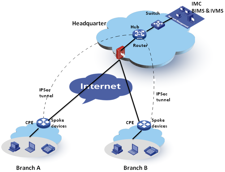
As network administrator, you want to enable IVMS to deploy its VPN tasks to CPEs managed by BIMS.
Task analysis
To use the cooperation schema of BIMS and IVMS in the above network (Figure 73), you can set the core switch as the hub device, set the two CPEs, CPE A and CPE B, as spoke devices, and then create the IPsec tunnel between the hub and spoke devices. The workflow is as follows:
1. CPE A and CPE B access the Internet through ADSL, and are assigned dynamic IP addresses.
2. An operator adds CPE records for CPE A and CPE B in BIMS to create two virtual CPEs.
|
|
NOTE: In this schema, you cannot use the BIMS zero-configuration solution. |
3. CPE A and CPE B boot, and send connection requests to BIMS.
4. BIMS authenticates the two CPEs. After the two CPEs pass the authentication, BIMS adds them as real CPEs, which means the CPEs can be practically managed by BIMS. For more information, see "Example 3: Deploying CPEs in branch offices."
5. Through setting the device service parameters, IVMS is authorized to access BIMS device information. It obtains information about BIMS devices using SOAP, and imports the BIMS devices.
6. An operator configures IPsec VPN parameters in IVMS, such as the network domain.
7. IVMS generates the IPsec VPN deployment task, and the task is synchronized to BIMS.
8. BIMS deploys the IPsec VPN configuration to CPEs, creating IPsec VPN between the hub device (at the headquarters) and the CPEs (at the branches).
9. The operator views the execution results of the task in BIMS.
For more information, see HPE IMC IPsec VPN Manager System Administrator Guide.
Example 5: Using CPE additional information
The additional information function is a flexible tool that helps you customize information for marking a CPE device. Additional information can be used as a variable in the configuration template. That is, if the content of a configuration template contains a variable whose name is the same as the variable name of a CPE additional information entry, when deploying the configuration template BIMS automatically sets the value of the variable to the default value specified in the additional information entry. This is a typical application of CPE additional information, as described in the following example.
Scenario description
As a network administrator, you are assigned to configure an additional information entry called "Location" for identifying the location of CPEs. In addition, you must customize a running configuration segment containing the variable corresponding to the additional information "Location," which will be used to configure the CPEs located in the headquarters and Branch A of the company.
Task analysis
To execute this scenario, perform the following tasks:
1. Add the additional information entry "Location."
2. Customize a configuration segment for the variable corresponding to the additional information "Location."
3. Create a deployment task to deploy the configuration segment to all CPEs located in the headquarters and Branch A of the company.
BIMS operations
The following sections describe the operations you must perform in BIMS for this example.
Adding additional information
1. Click Service > BIMS > Resource Management > CPE Additional Info.
2. On the CPE Additional Information List page, click Add.
3. On the Add CPE Additional Information page, enter Location in the Field Name field, and then enter the Variable Name of L.
4. Leave the Allow Null field as Yes.
5. Select Any Characters in the Field Type field.
6. Enter Headquarter in the Default Value field, and enter a Maximum Character Length of 100.
7. Click OK to add the Location additional information.
Customizing a configuration segment
To create a configuration template:
1. Click Service > BIMS > Configuration Management > Configuration Templates.
The Configuration Templates list appears.
2. Create a new folder or navigate to the folder to which you want to add the configuration template.
You can create a folder for storing the new configuration template. For more information, see "Creating a configuration template."
3. Click Add.
4. Specify the parameters of the configuration template.
In this example, enter the name of the configuration segment as segment–1220.cfg, and then select Configuration Segment in the Template Type field.
Enter the contents of the segment in the Content text box, which contains the L variable, as shown in Figure 74.
Figure 74 Contents of the configuration segment
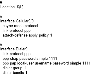
For more information, see "Creating a configuration template."
5. When you complete the attributes of the configuration template, click OK.
Creating a configuration deployment task
To deploy the configuration segment to the CPEs located in the headquarters and Branch A of the company:
1. Click Service > BIMS > Configuration Management > Deployment Guide.
2. On the Deployment Guide
page, click the Deploy Configuration icon![]() .
.
3. Select the folder that contains the configuration segment, and then select the configuration segment.
4. Select Running Configuration from the File Type to be Deployed list.
5. Click Select CPE, select the CPEs located in the headquarters and in Branch A, and then click OK.
The selected CPEs appear in the CPE-to-Deploy list.
6. Click Next.
Since the configuration segment contains a variable L, which is the same as the variable name of the Location additional information entry, BIMS automatically sets the variable value as the default value of the Headquarter additional information entry.
By default, the system sets the variable L as the default value of the CPE Location additional information entry. You can deselect the Use the CPE additional information by default check box to stop the system from setting the default value of Headquarter for the variable L, and define this variable yourself.
If you want to use the same parameters for all CPEs you selected in the previous step, select the Use the same parameters for the following CPEs check box. Then BIMS automatically sets the variable L of all the selected CPE to be the value defined on this page, and you do not need to configure the variable for all the selected CPEs one by one.
7. Click Next, and then set the variable L for the next CPEs to identify where the CPE is located.
8. After you finish configuring the variables, set the deployment task attributes, and then click Finish.
For more information, see "Deploying CPE configurations."
BIMS executes the task according to the task attributes, and deploys the segment to the target CPEs.
Example 6: Using Compliance Center
Compliance management helps solve potential configuration and security problems in the network. It provides an open interface to customize compliance policies, and execute CPE checking and violation fixing procedures. Based on a multi-task model, a compliance policy can be bound with one or more target CPE devices or classes. When BIMS finds configuration segments that violate the compliance policy, it raises a corresponding alarm, and immediately reports the violating details.
Scenario description
As a network administrator, you must configure a compliance policy for checking whether the interface link-protocol mode of the target CPE class—in this case 12508(HP)—is PPP. If certain CPEs violate the policy, you will check the violation details and fix them.
Task analysis
To execute this scenario, perform the following tasks:
1. Customize a compliance policy.
2. Create a new check task to bind the compliance policy with the target CPE class.
3. Check the violation reports for details.
4. Fix any violating configuration segments by using the fix function.
BIMS operations
The following sections describe the operations you must perform in BIMS for this example.
Adding a compliance policy
1. Click Service > BIMS > Compliance Center > Compliance Policy.
2. On the Compliance Policy page, click Add at the top of the Policy List pane.
3. On the Add Compliance Policy page, enter the policy name as interface link-protocol check.
4. For the description, enter Check the link-protocol mode in all interfaces.
5. Click Add Rule at the top of the Rule List pane.
6. On the Add Rule page, complete the parameters as follows:
¡ Name: link-protocol
¡ Severity Level: Major
¡ Check Type: Interface
¡ Start Identifier: interface*
¡ End Identifier: #
¡ Check Target: Latest backup running configuration
¡ Vendor: All
¡ CPE Model: 12508(HP)
¡ Description: Check the link-protocol of all interfaces
¡ Recover: No
¡ Rule Type: Basic
¡ Match Mode: Strict Match
¡ Match Patterns: link-protocol PPP
7. Click OK.
8. Go back to the Add Compliance Policy page, and test the added rule:
a. Click the Test icon ![]() in the Test column of
the link-protocol rule.
in the Test column of
the link-protocol rule.
b. On the Test Rule page, enter link-protocol PPP into the Test Content text box, and then click Test.
A message saying "Test content matches rule link-protocol." appears, which means the rule link-protocol passed the test.
9. Go back to the Add Compliance Policy page, and then click OK.
Adding a check task
1. Click Service > BIMS > Compliance Center > Check Task.
2. On the Check Task page, click Add.
3. On the Add Check Task page, complete the parameters as follows:
¡ Task Name: link-protocol check
¡ Severity Level: Major
¡ Execute Task: Immediately
¡ Description: Check the link-protocol of all interfaces
4. In the Compliance Policy List pane, delete any policies you do not need.
5. Click Select CPE Model to activate the CPE class selecting options in the Select CPEs Or CPE Models pane.
6. Click Select Model.
7. On the Select CPE Model page, select the check box to the left of 12508(HP), and then click OK.
Viewing the check reports
BIMS provides three check reports that show check details from execution results, compliance policy results, and CPE violating results. For information about each report, see "Managing a check task history." Since this example shows how to perform a compliance check task successfully, you would review the compliance policy check results.
To view the compliance policy check results:
1. Click Service > BIMS > Compliance Center > Task History.
The Task History page appears.
2. In the Task History
List pane, click the Results icon ![]() under the Operation column of task link-protocol check.
under the Operation column of task link-protocol check.
The Compliance Policy Check Results page appears.
3. Check the result details.
Fixing the violating configuration segments
After completing the compliance policy results checking procedure, you find there is a CPE named HP1 violating the compliance policy with a link-protocol of IP. You must fix the related configuration segment of the violating CPE, so you go back to the Check Task page to launch the fixing procedures.
To fix the violating CPE:
1. On the Check Task
page, select the check task link-protocol check, and then click the Fix icon ![]() under the Fix column.
under the Fix column.
2. On the Rule Violating Overview page, review the violating details from the list, and then select the check box to the left of the compliance policy link-protocol.
3. Click Fix in the upper left corner of the page.
4. Enter link-protocol PPP in the Fixing Commands text box, and then click Next.
5. On the Set Task Attributes page, complete the attributes as follows:
¡ Task Name: link-protocol fixing
¡ Task Type: Fix Violating CPEs
¡ Operation Type: One-off
¡ Operation Time: Immediately
¡ Description: link-protocol fixing
For more information, see "Fixing a check task."
6. Click Finish.
A results page appears.
The prompt box at the top of the results page tells you whether the check task was created successfully.
You can check task details, clone this task to add a new one, and add a deployment task directly. For more information, see "Fixing a check task."
Example 7: Deploying mobile branch devices
Network requirements
As shown in Figure 75, a company has IMC, BIMS, and MBM (subcomponent of BIMS) deployed at the headquarters, and mobile branch devices deployed at branch offices.
The mobile branch devices communicate with the headquarters through the ISP network, and branch hosts access the headquarters through the mobile branch devices.
Figure 75 Mobile branch network
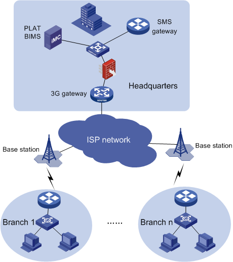
Task analysis
To meet the network requirements:
· Branch office operators must install a 3G modem inserted with a 3G SIM card on the mobile branch device, and power on the device.
· Headquarters office operators must perform the following tasks:
a. Configure global parameters in MBM, including the SMS gateway and BIMS parameters.
b. Add the mobile branch device information to MBM.
c. Create a configuration file.
d. Create an automatic deployment task, and bind the configuration file created in step c with the mobile branch devices.
e. Perform SMS deployment to send BIMS and SIM card parameters to mobile branch devices through SMS messages.
After a device receives the SMS message, it connects to the BIMS server and obtains the configuration file.
In this example, BIMS deploys DHCP configuration to the mobile branch devices. The devices receive the configuration, and act as the DHCP server to provide IP configurations to branch hosts for accessing the network.
Operation procedure
Preparing devices
Both the SMS gateway and mobile branch devices are MSR 20-20 routers.
Insert the 3G SIM card into the 3G modem, plug the 3G modem into the SIC card slot on the MSR 20-20 router, and then power on the router.
Configuring global parameters
Configure the SMS gateway and BIMS parameters in MBM.
Before you configure the SMS gateway, first add the SMS gateway device to IMC. MBM uses the SMS gateway to send BIMS and SIM card parameters as messages to devices during SMS deployment.
To configure the SMS gateway:
1. Click the Service tab.
2. From the navigation tree, select MBM > Option Management.
The Option Management page appears.
3. In the SMS Gateway Configuration area, click Select Device next to the SMS Gateway field.
The Select Devices window appears.
4. Select a device as the SMS gateway, and then click OK.
MBM auto-populates the management IP address of the selected device in the SMS Gateway field.
Make sure the SMS gateway is configured to send traps to IMC.
5. Enter the maximum number of transmission attempts in the Transmission Times field.
6. Enter the transmission timeout time in the Timeout (s) field.
If the mobile branch device failed to respond within the timeout time, MBM considers that the message delivery failed.
7. Click OK.
To configure BIMS parameters:
1. In the BIMS Parameter Configuration area, enter the URL of the ACS in the ACS URL field.
BIMS manages mobile branch devices through the ACS. Mobile branch devices access the specified URL to establish connections with the ACS.
2. Enter the user name and password used to access the ACS.
3. Click OK.
Adding a service provider view
Create a service provider view for the SIM card on the mobile branch device. SMS deployment can succeed only if the SIM card on the mobile branch device has been assigned to a specific service provider view that has the correct APN and PPP dialup settings in MBM.
To create a service provider view:
1. Click the Service tab.
2. From the navigation tree, select MBM > Resource Management > Service Provider View.
The Service Provider View List displays all service provider views.
3. Click Add.
4. Configure the following parameters:
a. Enter a name of the service provider view in the Name field.
b. Enter a description for the service provider view in the Description field.
c. Enter an access point name of the service provider in the APN field. The APN determines how the SIM card accesses the network.
d. Enter the PPP dialup settings for the service provider in the PPP Dialup field.
5. Click OK.
Importing mobile branch devices
1. Click the Service tab.
2. From the navigation tree, select MBM > Resource Management > Device.
The Device List page displays all mobile branch devices.
3. Click Import, and then select Import Device from File.
4. Click Browse to select the target file, or enter the directory of the file in the Select File field.
5. Click Next.
The device list page displays the imported mobile branch devices.
To delete unwanted devices, select the devices, and then click Delete.
6. Click Import.
The operation result appears at the top of the page.
Manually creating a configuration template
1. Click the Service tab.
2. From the navigation tree, select MBM > Configuration Management > Config Templates. The Configuration Templates page appears.
3. The configuration templates and folders stored at the template folder root level are displayed in the Configuration Templates list.
4. Navigate to the folder where you want to add the configuration template.
5. Click Add.
The Add Configuration Template page appears.
6. Specify the following information:
a. Enter brachdhcp.cfg as the configuration template name.
b. Select Segment from the Template Type field.
c. Select Console from the Segment Type list.
d. Select RootFolder from the Folder list.
e. Click Select Class next to the Applicable CPEs field. The Select CPE Class dialog box appears. Enter MSR 20-20 in the Class Name field, and then click Query. Select MSR 20-20, and then click OK.
f. Enter a description for the configuration template in the Description field.
g. Enter the contents of the configuration segment in the Content field.
For example, you can enter the following contents:
#Enable NAT.
#
interface Cellular0/0
nat outbound
#Configure the IP address range of the private network.
#
interface Ethernet0/0
port link-mode route
ip address 172.16.1.1 255.255.255.0
#Configure the DHCP server.
#
dhcp enable
#
dhcp server ip-pool pc
network 172.16.1.0 mask 255.255.255.0
gateway-list 172.16.1.1
dns-list 8.8.8.8
7. Click OK.
The configuration template you created appears in the selected template folder.
Creating an automatic deployment task
Bind the configuration template with mobile branch devices. After the devices go online, BIMS automatically deploys the configuration file to the devices.
To create an automatic deployment task:
1. Click the Service tab
2. From the navigation tree, select MBM > Service Management > Auto Deploy Config.
The Auto Deploy Configuration page appears.
3. Select RootFolder from the Folder list.
4. Select brachdhcp.cfg from the File Name list.
5. Select Running configuration from the File Type to be Deployed list.
6. Click Select CPE, select the virtual CPEs to be deployed, and then click OK.
The selected CPEs appear in the CPE-to-Deploy list.
7. View the Check Result of each CPE you want to deploy.
8. Click Next.
9. Set the following attributes to specify how the task is executed:
¡ Task Name—Enter a task name. By default, the task name is task + current time.
¡ Description—Enter the task description.
10. Click Finish.
Performing the SMS deployment
The SMS deployment works as follows:
1. MBM uses the SMS gateway to send the BIMS parameters and SIM card parameters in SMS messages to the mobile branch devices.
2. A device receives the SMS message and establishes a connection to the BIMS server, so that the device comes online in MBM and BIMS.
3. After the device is online, BIMS execute the automatic deployment task to deploy the configuration file to the device.
In this configuration example, the MSR routers in the branch offices receive DHCP configuration from BIMS. They will act as DHCP servers to provide IP addresses for PCs to access the network.
To perform the SMS deployment:
1. Click the Service tab.
2. From the navigation tree, select MBM > Resource Management > Device.
The Device List page displays all mobile branch devices.
3. Select the target devices, and then click Deploy SMS.
The SMS Deployment page appears. At the
top of the page, a rotating icon![]() appears, indicating that SMS is being deployed.
appears, indicating that SMS is being deployed.
The SMS Deployment page also displays the devices in the SMS deployment progress in the device list. Column labels of the device list include Device Name, OUI, Serial Number, Primary Phone Number, Primary Service Provider, Secondary Phone Number, Secondary Service Provider, and Deployment Result.
