- Table of Contents
-
- 09-IP Multicast Configuration Guide
- 00-Preface
- 01-Multicast overview
- 02-IGMP snooping configuration
- 03-Multicast routing and forwarding configuration
- 04-IGMP configuration
- 05-PIM configuration
- 06-MSDP configuration
- 07-Multicast VPN configuration
- 08-MLD snooping configuration
- 09-IPv6 multicast routing and forwarding configuration
- 10-MLD configuration
- 11-IPv6 PIM configuration
- Related Documents
-
| Title | Size | Download |
|---|---|---|
| 03-Multicast routing and forwarding configuration | 303.21 KB |
Configuring multicast routing and forwarding
About multicast routing and forwarding
Usages of static multicast routes
Multicast forwarding across unicast subnets
Restrictions: Hardware compatibility with multicast routing and forwarding
Restrictions and guidelines: Multicast routing and forwarding configuration
Multicast routing and forwarding tasks at a glance
Prerequisites for multicast routing and forwarding
Configuring static multicast routes
Specifying the longest prefix match principle
Configuring multicast load splitting
Configuring a multicast forwarding boundary
Enabling multicast forwarding between sub-VLANs of a super VLAN
Setting the maximum number of cached unknown multicast packets
Display and maintenance commands for multicast routing and forwarding
Multicast routing and forwarding configuration examples
Example: Changing an RPF route
Example: Creating an RPF route
Example: Configuring multicast forwarding over a GRE tunnel
Example: Configuring multicast forwarding over ADVPN tunnels
Troubleshooting multicast routing and forwarding
Static multicast route failure
Configuring multicast routing and forwarding
About multicast routing and forwarding
Each multicast routing protocol has its own routing table. Multicast routing information in routing entries generated by the multicast routing protocols and statically configured multicast routing entries are summarized in a set of (S, G) and (*, G) entries. All the (S, G) and (*, G) entries form a general multicast routing table. The optimal multicast routing entries in the general multicast routing table are added to the multicast forwarding table to guide multicast data forwarding.
RPF check mechanism
A multicast routing protocol uses reverse path forwarding (RPF) check to ensure the multicast data delivery along the correct path and to avoid data loops.
RPF check process
A multicast device performs the RPF check on a multicast packet as follows:
1. Chooses an optimal route back to the packet source separately from the unicast, MBGP, and static multicast routing tables.
The term "packet source" means different things in different situations:
¡ For a packet that travels along the SPT, the packet source is the multicast source.
¡ For a packet that travels along the RPT, the packet source is the RP.
¡ For a bootstrap message originated from the BSR, the packet source is the BSR.
For more information about the concepts of SPT, RPT, source-side RPT, RP, and BSR, see "Configuring PIM."
2. Selects one of the three optimal routes as the RPF route as follows:
¡ If the device uses the longest prefix match principle, the route with the highest subnet mask becomes the RPF route. If the routes have the same mask, the route with the highest route preference becomes the RPF route. If the routes have the same route preference, the unicast route becomes the RPF route. If equal cost routes exist, the route with the highest next hop IP address becomes the RPF route.
For more information about the route preference, see Layer 3—IP Routing Configuration Guide.
¡ If the device does not use the longest prefix match principle, the route with the highest route preference becomes the RPF route. If the routes have the same preference, the unicast route becomes the RPF route. If equal cost routes exist, the route with the highest next hop IP address becomes the RPF route.
The RPF route contains the RPF interface and RPF neighbor information.
¡ If the RPF route is a unicast route or MBGP route, the outgoing interface is the RPF interface and the next hop is the RPF neighbor.
¡ If the RPF route is a static multicast route, the RPF interface and RPF neighbor are specified in the route.
3. Determines whether the packet arrived at the RPF interface.
¡ If the packet arrived at the RPF interface, the RPF check succeeds and the packet is forwarded.
¡ If the packet arrived at the non-RPF interface, the RPF check fails and the packet is discarded.
RPF check implementation in multicast
Implementing an RPF check on each received multicast packet brings a big burden to the device. The use of a multicast forwarding table is the solution to this issue. When the device creates a multicast forwarding entry for an (S, G) packet, it sets the RPF interface of the packet as the incoming interface of the (S, G) entry. After the device receives another (S, G) packet, it looks up the multicast forwarding table for a matching (S, G) entry.
· If no match is found, the device first determines the RPF route back to the packet source and the RPF interface. Then, it creates a forwarding entry with the RPF interface as the incoming interface and makes the following judgments:
¡ If the receiving interface is the RPF interface, the RPF check succeeds and the device forwards the packet out of all the outgoing interfaces.
¡ If the receiving interface is not the RPF interface, the RPF check fails and the device discards the packet.
· If a match is found and the matching forwarding entry contains the receiving interface, the device forwards the packet out of all the outgoing interfaces.
· If a match is found but the matching forwarding entry does not contain the receiving interface, the device determines the RPF route back to the packet source. Then, the device performs one of the following actions:
¡ If the RPF interface is the incoming interface, it means that the forwarding entry is correct but the packet traveled along a wrong path. The packet fails the RPF check, and the device discards the packet.
¡ If the RPF interface is not the incoming interface, it means that the forwarding entry has expired. The device replaces the incoming interface with the RPF interface and matches the receiving interface against the RPF interface. If the receiving interface is the RPF interface, the device forwards the packet out of all outgoing interfaces. Otherwise, it discards the packet.
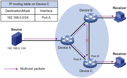
As shown in Figure 1, assume that unicast routes are available on the network, MBGP is not configured, and no static multicast routes have been configured on Device C. Multicast packets travel along the SPT from the multicast source to the receivers. The multicast forwarding table on Device C contains the (S, G) entry, with Port A as the incoming interface.
· If a multicast packet arrives at Device C on Port A, the receiving interface is the incoming interface of the (S, G) entry. Device C forwards the packet out of all outgoing interfaces.
· If a multicast packet arrives at Device C on Port B, the receiving interface is not the incoming interface of the (S, G) entry. Device C searches its unicast routing table and finds that the outgoing interface to the source (the RPF interface) is Port A. In this case, the (S, G) entry is correct, but the packet traveled along a wrong path. The packet fails the RPF check and Device C discards the packet.
Usages of static multicast routes
A static multicast route can change an RPF route or create an RPF route.
Changing an RPF route
Typically, the topology structure of a multicast network is the same as that of a unicast network, and multicast traffic follows the same transmission path as unicast traffic does. You can configure a static multicast route for a multicast source to change the RPF route. As a result, the device creates a transmission path for multicast traffic that is different from the transmission path for unicast traffic.
Figure 2 Changing an RPF route
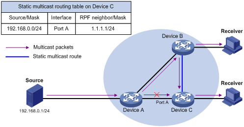
As shown in Figure 2, when no static multicast route is configured, Device C's RPF neighbor on the path back to the source is Device A. The multicast data from the source travels through Device A to Device C. You can configure a static multicast route on Device C and specify Device B as Device C's RPF neighbor on the path back to the source. The multicast data from the source travels along the path: Device A to Device B and then to Device C.
Creating an RPF route
When a unicast route is blocked, multicast forwarding might be stopped due to lack of an RPF route. You can configure a static multicast route to create an RPF route. In this way, a multicast routing entry is created to guide multicast forwarding.
Figure 3 Creating an RPF route
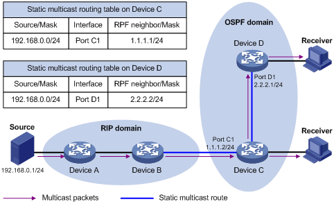
As shown in Figure 3, the RIP domain and the OSPF domain are unicast isolated from each other. For the receiver hosts in the OSPF domain to receive multicast packets from the multicast source in the RIP domain, you must configure Device C and Device D as follows:
· On Device C, configure a static multicast route for the multicast source and specify Device B as the RPF neighbor.
· On Device D, configure a static multicast route for the multicast source and specify Device C as the RPF neighbor.
Multicast forwarding across unicast subnets
Devices forward the multicast data from a multicast source hop by hop along the forwarding tree, but some devices might not support multicast protocols in a network. When the multicast data is forwarded to a device that does not support IP multicast, the forwarding path is blocked. In this case, you can enable multicast forwarding across two unicast subnets by establishing a tunnel between the devices at the edges of the two unicast subnets.
Figure 4 Multicast data transmission through a tunnel
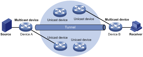
As shown in Figure 4, a tunnel is established between Device A and Device B. Device A encapsulates the multicast data in unicast IP packets, and forwards them to Device B across the tunnel through unicast devices. Then, Device B strips off the unicast IP header and continues to forward the multicast data to the receiver.
To use this tunnel only for multicast traffic, configure the tunnel as the outgoing interface only for multicast routes.
Restrictions: Hardware compatibility with multicast routing and forwarding
|
Hardware |
Multicast routing and forwarding compatibility |
|
MSR810, MSR810-W, MSR810-W-DB, MSR810-LM, MSR810-W-LM, MSR810-10-PoE, MSR810-LM-HK, MSR810-W-LM-HK, MSR810-LMS-EA |
Yes |
|
MSR810-LMS, MSR810-LUS |
No |
|
MSR2600-6-X1, MSR2600-10-X1 |
Yes |
|
MSR 2630 |
Yes |
|
MSR3600-28, MSR3600-51 |
Yes |
|
MSR3600-28-SI, MSR3600-51-SI |
No |
|
MSR3600-28-X1, MSR3600-28-X1-DP, MSR3600-51-X1, MSR3600-51-X1-DP |
Yes |
|
MSR3610-I-DP, MSR3610-IE-DP |
Yes |
|
MSR3610-X1, MSR3610-X1-DP, MSR3610-X1-DC, MSR3610-X1-DP-DC |
Yes |
|
MSR 3610, MSR 3620, MSR 3620-DP, MSR 3640, MSR 3660 |
Yes |
|
MSR3610-G, MSR3620-G |
Yes |
Restrictions and guidelines: Multicast routing and forwarding configuration
The device can route and forward multicast data only through the primary IP addresses of interfaces, rather than their secondary addresses or unnumbered IP addresses. For more information about primary and secondary IP addresses, and IP unnumbered, see Layer 3—IP Services Configuration Guide.
Multicast routing and forwarding tasks at a glance
To configure multicast routing and forwarding, perform the following tasks:
1. Enabling IP multicast routing
2. (Optional.) Configuring static multicast routes
3. (Optional.) Specifying the longest prefix match principle
4. (Optional.) Configuring multicast load splitting
5. (Optional.) Configuring a multicast forwarding boundary
6. (Optional.) Enabling multicast forwarding between sub-VLANs of a super VLAN
7. (Optional.) Setting the maximum number of cached unknown multicast packets
Prerequisites for multicast routing and forwarding
Before you configure multicast routing and forwarding, configure a unicast routing protocol so that all devices in the domain can interoperate at the network layer.
Enabling IP multicast routing
About IP multicast routing
Enable IP multicast routing before you configure any Layer 3 multicast functionality on the public network or VPN instance.
Procedure
1. Enter system view.
system-view
2. Enable IP multicast routing and enter MRIB view.
multicast routing [ vpn-instance vpn-instance-name ]
By default, IP multicast routing is disabled.
Configuring static multicast routes
About static multicast routes
To configure a static multicast route for a multicast source, you can specify an RPF interface or an RPF neighbor for the multicast traffic from that source.
Restrictions and guidelines
Static multicast routes take effect only on the multicast devices on which they are configured, and will not be advertised throughout the network or redistributed to other devices.
Procedure
1. Enter system view.
system-view
2. Configure a static multicast route.
ip rpf-route-static [ vpn-instance vpn-instance-name ] source-address { mask-length | mask } { rpf-nbr-address | interface-type interface-number } [ preference preference ]
3. (Optional.) Delete all static multicast routes.
delete ip rpf-route-static [ vpn-instance vpn-instance-name ]
You can use the undo ip rpf-route-static command to delete a specific static multicast route or use the delete ip rpf-route-static command to delete all static multicast routes.
Specifying the longest prefix match principle
About the longest prefix match principle
You can enable the device to use the longest prefix match principle for RPF route selection. For more information about RPF route selection, see "RPF check process."
Procedure
1. Enter system view.
system-view
2. Enter MRIB view.
multicast routing [ vpn-instance vpn-instance-name ]
3. Specify the longest prefix match principle.
longest-match
By default, the route preference principle is used.
Configuring multicast load splitting
About multicast load splitting
You can enable the device to split multiple data flows on a per-source basis or on a per-source-and-group basis. This optimizes the traffic delivery.
Restrictions and guidelines
This feature does not take effect on BIDIR-PIM.
Procedure
1. Enter system view.
system-view
2. Enter MRIB view.
multicast routing [ vpn-instance vpn-instance-name ]
3. Configure multicast load splitting.
load-splitting { source | source-group }
By default, multicast load splitting is disabled.
Configuring a multicast forwarding boundary
About a multicast forwarding boundaries
You can configure an interface as a multicast forwarding boundary for a multicast group range. The interface cannot receive or forward multicast packets for the group range.
Restrictions and guidelines
You do not need to enable IP multicast before this configuration.
Procedure
system-view
2. Enter interface view.
interface interface-type interface-number
3. Configure the interface as a multicast forwarding boundary for a multicast group range.
multicast boundary group-address { mask-length | mask }
By default, an interface is not a multicast forwarding boundary.
Enabling multicast forwarding between sub-VLANs of a super VLAN
About multicast forwarding between sub-VLANs of a super VLAN
A super VLAN is associated with multiple sub-VLANs. Sub-VLANs are isolated with each other at Layer 2. For information about the super VLAN and sub-VLANs, see Layer 2—LAN Switching Configuration Guide.
Procedure
1. Enter system view.
system-view
2. Enter VLAN interface view.
interface vlan-interface interface-number
3. Enable multicast forwarding between sub-VLANs that are associated with a super VLAN.
multicast forwarding supervlan community
By default, multicast data cannot be forwarded between sub-VLANs that are associated with a super VLAN.
4. Return to system view.
quit
5. Return to user view.
quit
6. Clear all multicast forwarding entries with the super VLAN interface as the incoming interface.
reset multicast [ vpn-instance vpn-instance-name ] forwarding-table incoming-interface { interface-type interface-number }
The multicast forwarding supervlan community command takes effect only after you perform this step.
Setting the maximum number of cached unknown multicast packets
About setting the maximum number of cached unknown multicast packets
The device caches a multicast packet for a period of time if no matching multicast forwarding entry is found for the packet. If a multicast forwarding entry is established for the packet within the time period, the device forwards the packet. This mechanism prevents the device from mistakenly dropping multicast packets when the multicast forwarding entries for these packets are to be created.
You can set the maximum number of unknown multicast packets that can be cached for an (S, G) entry, in total, or both.
Restrictions and guidelines
As a best practice, set the value in the multicast forwarding-table cache-unknown total command to be far greater than the value in the multicast forwarding-table cache-unknown per-entry command.
Procedure
1. Enter system view.
system-view
2. Set the maximum number of unknown multicast packets that can be cached for an (S, G) entry.
multicast forwarding-table cache-unknown per-entry per-entry-limit
By default, the device can cache only one unknown multicast packet for an (S, G) entry.
3. Set the maximum number of unknown multicast packets that can be cached in total.
multicast forwarding-table cache-unknown total total-limit
By default, the device can cache 1024 unknown multicast packets in total.
Display and maintenance commands for multicast routing and forwarding
|
|
CAUTION: The reset commands might cause multicast data transmission failures. |
Execute display commands in any view and reset commands in user view.
|
Task |
Command |
|
Display information about the interfaces maintained by the MRIB. |
display mrib [ vpn-instance vpn-instance-name ] interface [ interface-type interface-number ] |
|
Display multicast boundary information. |
display multicast [ vpn-instance vpn-instance-name ] boundary [ group-address [ mask-length | mask ] ] [ interface interface-type interface-number ] |
|
Display multicast fast forwarding entries. |
In standalone mode: display multicast [ vpn-instance vpn-instance-name ] fast-forwarding cache [ source-address | group-address ] * In IRF mode: display multicast [ vpn-instance vpn-instance-name ] fast-forwarding cache [ source-address | group-address ] * [ slot slot-number ] |
|
Display DF information. |
In standalone mode: display multicast [ vpn-instance vpn-instance-name ] forwarding df-info [ rp-address ] [ verbose ] In IRF mode: display multicast [ vpn-instance vpn-instance-name ] forwarding df-info [ rp-address ] [ verbose ] [ slot slot-number ] |
|
Display statistics for multicast forwarding events. |
In standalone mode: display multicast [ vpn-instance vpn-instance-name ] forwarding event In IRF mode: display multicast [ vpn-instance vpn-instance-name ] forwarding event [ slot slot-number] |
|
Display multicast forwarding entries. |
In standalone mode: display multicast [ vpn-instance vpn-instance-name ] forwarding-table [ source-address [ mask { mask-length | mask } ] | group-address [ mask { mask-length | mask } ]| incoming-interface interface-type interface-number | outgoing-interface { exclude | include | match } interface-type interface-number | statistics ] * In IRF mode: display multicast [ vpn-instance vpn-instance-name ] forwarding-table [ source-address [ mask { mask-length | mask } ] | group-address [ mask { mask-length | mask } ] | incoming-interface interface-type interface-number | outgoing-interface { exclude | include | match } interface-type interface-number | slot slot-number | statistics ] * |
|
Display information about the DF list in the multicast forwarding table. |
In standalone mode: display multicast [ vpn-instance vpn-instance-name ] forwarding-table df-list [ group-address ] [ verbose ] In IRF mode: display multicast [ vpn-instance vpn-instance-name ] forwarding-table df-list [ group-address ] [ verbose ] [ slot slot-number ] |
|
Display multicast routing entries. |
display multicast [ vpn-instance vpn-instance-name ] routing-table [ source-address [ mask { mask-length | mask } ] | group-address [ mask { mask-length | mask } ] | incoming-interface interface-type interface-number | outgoing-interface { exclude | include | match } interface-type interface-number ] * |
|
Display static multicast routing entries. |
display multicast [ vpn-instance vpn-instance-name ] routing-table static [ source-address { mask-length | mask } ] |
|
Display RPF information for a multicast source. |
display multicast [ vpn-instance vpn-instance-name ] rpf-info source-address [ group-address ] |
|
Clear multicast fast forwarding entries. |
In standalone mode: reset multicast [ vpn-instance vpn-instance-name ] fast-forwarding cache { { source-address | group-address } * | all } In IRF mode: reset multicast [ vpn-instance vpn-instance-name ] fast-forwarding cache { { source-address | group-address } * | all } [ slot slot-number ] |
|
Clear statistics for multicast forwarding events. |
reset multicast [ vpn-instance vpn-instance-name ] forwarding event |
|
Clear multicast forwarding entries. |
reset multicast [ vpn-instance vpn-instance-name ] forwarding-table { { source-address [ mask { mask-length | mask } ] | group-address [ mask { mask-length | mask } ] | incoming-interface { interface-type interface-number } } * | all } |
|
Clear multicast routing entries. |
reset multicast [ vpn-instance vpn-instance-name ] routing-table { { source-address [ mask { mask-length | mask } ] | group-address [ mask { mask-length | mask } ] | incoming-interface interface-type interface-number } * | all } |
|
|
NOTE: · When you clear a multicast routing entry, the associated multicast forwarding entry is also cleared. · When you clear a multicast forwarding entry, the associated multicast routing entry is also cleared. |
Multicast routing and forwarding configuration examples
Example: Changing an RPF route
Network configuration
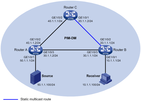
As shown in Figure 5:
· PIM-DM runs on the network.
· All routers on the network support multicast.
· Router A, Router B, and Router C run OSPF.
· Typically, the receiver host can receive the multicast data from the source through the path: Router A to Router B, which is the same as the unicast route.
Configure the routers so that the multicast data from the source travels to the receiver along the following path: Router A to Router C to Router B. This path is different from the unicast route.
Procedure
1. Assign an IP address and subnet mask for each interface, as shown in Figure 5. (Details not shown.)
2. Configure OSPF on the routers in the PIM-DM domain. (Details not shown.)
3. Enable IP multicast routing, and enable IGMP and PIM-DM:
# On Router B, enable IP multicast routing.
<RouterB> system-view
[RouterB] multicast routing
[RouterB-mrib] quit
# Enable IGMP on the receiver-side interface GigabitEthernet 1/0/1.
[RouterB] interface gigabitethernet 1/0/1
[RouterB-GigabitEthernet1/0/1] igmp enable
[RouterB-GigabitEthernet1/0/1] quit
# Enable PIM-DM on the other interfaces.
[RouterB] interface gigabitethernet 1/0/2
[RouterB-GigabitEthernet1/0/2] pim dm
[RouterB-GigabitEthernet1/0/2] quit
[RouterB] interface gigabitethernet 1/0/3
[RouterB-GigabitEthernet1/0/3] pim dm
[RouterB-GigabitEthernet1/0/3] quit
# On Router A, enable IP multicast routing.
<RouterA> system-view
[RouterA] multicast routing
[RouterA-mrib] quit
# Enable PIM-DM on each interface.
[RouterA] interface gigabitethernet 1/0/1
[RouterA-GigabitEthernet1/0/1] pim dm
[RouterA-GigabitEthernet1/0/1] quit
[RouterA] interface gigabitethernet 1/0/2
[RouterA-GigabitEthernet1/0/2] pim dm
[RouterA-GigabitEthernet1/0/2] quit
[RouterA] interface gigabitethernet 1/0/3
[RouterA-GigabitEthernet1/0/3] pim dm
[RouterA-GigabitEthernet1/0/3] quit
# Enable IP multicast routing and PIM-DM on Router C in the same way Router A is configured. (Details not shown.)
4. Display RPF information for the source on Router B.
[RouterB] display multicast rpf-info 50.1.1.100
RPF information about source 50.1.1.100:
RPF interface: GigabitEthernet1/0/3, RPF neighbor: 30.1.1.2
Referenced route/mask: 50.1.1.0/24
Referenced route type: igp
Route selection rule: preference-preferred
Load splitting rule: disable
Source AS: 0
C-multicast route target: 0x0000000000000000
The output shows that the current RPF route on Router B is contributed by a unicast routing protocol and the RPF neighbor is Router A.
5. On Router B, configure a static multicast route to the source and specify Router C as the RPF neighbor.
[RouterB] ip rpf-route-static 50.1.1.0 24 20.1.1.2
Verifying the configuration
# Display RPF information for the source on Router B.
[RouterB] display multicast rpf-info 50.1.1.100
RPF information about source 50.1.1.100:
RPF interface: GigabitEthernet1/0/2, RPF neighbor: 20.1.1.2
Referenced route/mask: 50.1.1.0/24
Referenced route type: multicast static
Route selection rule: preference-preferred
Load splitting rule: disable
Source AS: 0
C-multicast route target: 0x0000000000000000
The output shows the following information:
· The RPF route on Router B is the configured static multicast route.
· The RPF neighbor of Router B is Router C.
Example: Creating an RPF route
Network configuration
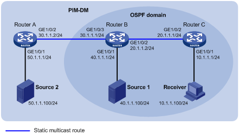
As shown in Figure 6:
· PIM-DM runs on the network.
· All routers on the network support IP multicast.
· Router B and Router C run OSPF, and have no unicast routes to Router A.
· Typically, the receiver host receives the multicast data from Source 1 in the OSPF domain.
Configure the routers so that the receiver host can receive multicast data from Source 2, which is outside the OSPF domain.
Procedure
1. Assign an IP address and subnet mask for each interface, as shown in Figure 6. (Details not shown.)
2. Configure OSPF on Router B and Router C. (Details not shown.)
3. Enable IP multicast routing, and enable IGMP and PIM-DM:
# On Router C, enable IP multicast routing.
<RouterC> system-view
[RouterC] multicast routing
[RouterC-mrib] quit
# Enable IGMP on the receiver-side interface GigabitEthernet 1/0/1.
[RouterC] interface gigabitethernet 1/0/1
[RouterC-GigabitEthernet1/0/1] igmp enable
[RouterC-GigabitEthernet1/0/1] quit
# Enable PIM-DM on GigabitEthernet 1/0/2.
[RouterC] interface gigabitethernet 1/0/2
[RouterC-GigabitEthernet1/0/2] pim dm
[RouterC-GigabitEthernet1/0/2] quit
# On Router A, enable IP multicast routing.
<RouterA> system-view
[RouterA] multicast routing
[RouterA-mrib] quit
# Enable PIM-DM on each interface.
[RouterA] interface gigabitethernet 1/0/1
[RouterA-GigabitEthernet1/0/1] pim dm
[RouterA-GigabitEthernet1/0/1] quit
[RouterA] interface gigabitethernet 1/0/2
[RouterA-GigabitEthernet1/0/2] pim dm
[RouterA-GigabitEthernet1/0/2] quit
# Enable IP multicast routing and PIM-DM on Router B in the same way Router A is configured. (Details not shown.)
4. Display RPF information for Source 2 on Router B and Router C.
[RouterB] display multicast rpf-info 50.1.1.100
[RouterC] display multicast rpf-info 50.1.1.100
No output is displayed because no RPF routes to Source 2 exist on Router B and Router C.
5. Configure a static multicast route:
# Configure a static multicast route on Router B and specify Router A as its RPF neighbor to Source 2.
[RouterB] ip rpf-route-static 50.1.1.0 24 30.1.1.2
# Configure a static multicast route on Router C and specify Router B as its RPF neighbor to Source 2.
[RouterC] ip rpf-route-static 50.1.1.0 24 20.1.1.2
Verifying the configuration
# Display RPF information for Source 2 on Router B.
[RouterB] display multicast rpf-info 50.1.1.100
RPF information about source 50.1.1.100:
RPF interface: GigabitEthernet1/0/3, RPF neighbor: 30.1.1.2
Referenced route/mask: 50.1.1.0/24
Referenced route type: multicast static
Route selection rule: preference-preferred
Load splitting rule: disable
Source AS: 0
C-multicast route target: 0x0000000000000000
# Display RPF information for Source 2 on Router C.
[RouterC] display multicast rpf-info 50.1.1.100
RPF information about source 50.1.1.100:
RPF interface: GigabitEthernet1/0/2, RPF neighbor: 20.1.1.2
Referenced route/mask: 50.1.1.0/24
Referenced route type: multicast static
Route selection rule: preference-preferred
Load splitting rule: disable
Source AS: 0
C-multicast route target: 0x0000000000000000
The output shows that the RPF routes to Source 2 exist on Router B and Router C. These RPF routes are the configured static multicast routes.
Example: Configuring multicast forwarding over a GRE tunnel
Network configuration
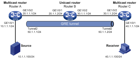
As shown in Figure 7:
· Multicast routing and PIM-DM are enabled on Router A and Router C. Router B does not support multicast.
· Router A, Router B, and Router C run OSPF. The source-side interface GigabitEthernet 1/0/1 on Router A does not run OSPF.
Configure a GRE tunnel so that the receiver host can receive the multicast data from the source.
Procedure
1. Assign an IP address and mask for each interface, as shown in Figure 7. (Details not shown.)
2. Configure OSPF on all the routers. Do not enable OSPF on GigabitEthernet 1/0/1 on Router A. (Details not shown.)
3. Configure a GRE tunnel:
# Create a GRE tunnel interface Tunnel 2 on Router A, and specify the tunnel mode as GRE/IPv4.
<RouterA> system-view
[RouterA] interface tunnel 2 mode gre
# Assign an IP address to interface Tunnel 2, and specify its source and destination addresses.
[RouterA-Tunnel2] ip address 50.1.1.1 24
[RouterA-Tunnel2] source 20.1.1.1
[RouterA-Tunnel2] destination 30.1.1.2
[RouterA-Tunnel2] quit
# Create a GRE tunnel interface Tunnel 2 on Router C, and specify the tunnel mode as GRE/IPv4.
<RouterC> system-view
[RouterC] interface tunnel 2 mode gre
# Assign an IP address to interface Tunnel 2, and specify its source and destination addresses.
[RouterC-Tunnel2] ip address 50.1.1.2 24
[RouterC-Tunnel2] source 30.1.1.2
[RouterC-Tunnel2] destination 20.1.1.1
[RouterC-Tunnel2] quit
4. Enable IP multicast routing, PIM-DM, and IGMP:
# On Router A, enable IP multicast routing.
[RouterA] multicast routing
[RouterA-mrib] quit
# Enable PIM-DM on each interface.
[RouterA] interface gigabitethernet 1/0/1
[RouterA-GigabitEthernet1/0/1] pim dm
[RouterA-GigabitEthernet1/0/1] quit
[RouterA] interface gigabitethernet 1/0/2
[RouterA-GigabitEthernet1/0/2] pim dm
[RouterA-GigabitEthernet1/0/2] quit
[RouterA] interface tunnel 2
[RouterA-Tunnel2] pim dm
[RouterA-Tunnel2] quit
# On Router C, enable IP multicast routing.
[RouterC] multicast routing
[RouterC-mrib] quit
# Enable IGMP on the receiver-side interface GigabitEthernet 1/0/1.
[RouterC] interface gigabitethernet 1/0/1
[RouterC-GigabitEthernet1/0/1] igmp enable
[RouterC-GigabitEthernet1/0/1] quit
# Enable PIM-DM on other interfaces.
[RouterC] interface gigabitethernet 1/0/2
[RouterC-GigabitEthernet1/0/2] pim dm
[RouterC-GigabitEthernet1/0/2] quit
[RouterC] interface tunnel 2
[RouterC-Tunnel2] pim dm
[RouterC-Tunnel2] quit
5. On Router C, configure a static multicast route to the source and specify Router A as the RPF neighbor.
[RouterC] ip rpf-route-static 10.1.1.0 24 50.1.1.1
Verifying the configuration
# Send an IGMP report from the receiver to join multicast group 225.1.1.1. (Details not shown.)
# Send multicast data from the source to multicast group 225.1.1.1. (Details not shown.)
# Display PIM routing entries on Router C.
[RouterC] display pim routing-table
Total 1 (*, G) entry; 1 (S, G) entry
(*, 225.1.1.1)
Protocol: pim-dm, Flag: WC
UpTime: 00:04:25
Upstream interface: NULL
Upstream neighbor: NULL
RPF prime neighbor: NULL
Downstream interface(s) information:
Total number of downstreams: 1
1: GigabitEthernet1/0/1
Protocol: igmp, UpTime: 00:04:25, Expires: -
(10.1.1.100, 225.1.1.1)
Protocol: pim-dm, Flag: ACT
UpTime: 00:06:14
Upstream interface: Tunnel2
Upstream neighbor: 50.1.1.1
RPF prime neighbor: 50.1.1.1
Downstream interface(s) information:
Total number of downstreams: 1
1: GigabitEthernet1/0/1
Protocol: pim-dm, UpTime: 00:04:25, Expires: -
The output shows that Router A is the RPF neighbor of Router C and the multicast data from Router A is delivered over the GRE tunnel to Router C.
Example: Configuring multicast forwarding over ADVPN tunnels
Network configuration
As shown in Figure 8:
· An ADVPN tunnel is established between each spoke and hub.
· All hubs and spokes support IP multicast. PIM-SM runs on them, and NBMA runs on their ADVPN tunnel interfaces.
· OSPF runs on all hubs and spokes.
Configure the routers so that Spoke 1 can receive multicast data from the source.
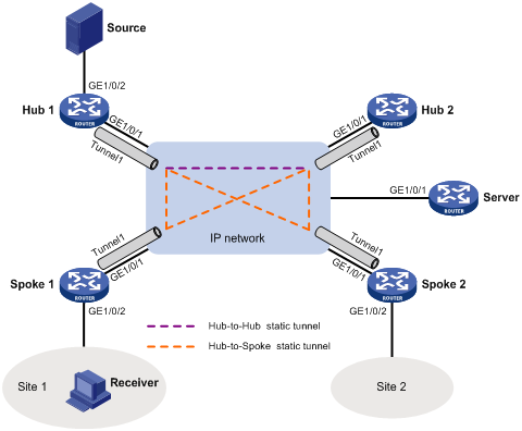
Table 1 Interface and IP address assignment
|
Device |
Interface |
IP address |
Device |
Interface |
IP address |
|
Hub 1 |
GE1/0/1 |
100.1.1.1/24 |
Spoke 1 |
GE1/0/1 |
100.1.1.3/24 |
|
Hub 1 |
Tunnel1 |
192.168.0.1/24 |
Spoke 1 |
Tunnel1 |
192.168.0.3/24 |
|
Hub 1 |
Loop0 |
1.1.1.1/32 |
Spoke 1 |
GE1/0/2 |
20.1.1.10/24 |
|
Hub 1 |
GE1/0/2 |
10.1.1.10/24 |
Spoke 2 |
GE1/0/1 |
100.1.1.4/24 |
|
Hub 2 |
GE1/0/1 |
100.1.1.2/24 |
Spoke 2 |
Tunnel1 |
192.168.0.4/24 |
|
Hub 2 |
Tunnel1 |
192.168.0.2/24 |
Server |
GE1/0/1 |
100.1.1.100/24 |
|
Hub 2 |
Loop0 |
2.2.2.2/32 |
|
|
|
Procedure
1. Assign an IP address and subnet mask to each interface, as shown in Table 1. (Details not shown.)
2. Configure ADVPN:
a. Configure the VAM server:
# Create a ADVPN domain named abc.
<Server> system-view
[Server] vam server advpn-domain abc id 1
# Set the pre-shared key to 123456.
[Server-vam-server-domain-abc]pre-shared-key simple 123456
# Configure the VAM server not to authenticate VAM clients.
[Server-vam-server-domain-abc] authentication-method none
# Enable the VAM server.
[Server-vam-server-domain-abc] server enable
# Create hub group 0.
[Server-vam-server-domain-abc] hub-group 0
# Specify private IPv4 addresses for hubs in hub group 0.
[Server-vam-server-domain-abc-hub-group-0] hub private-address 192.168.0.1
[Server-vam-server-domain-abc-hub-group-0] hub private-address 192.168.0.2
# Specify a private IPv4 address range for spokes in hub group 0.
[Server-vam-server-domain-abc-hub-group-0] spoke private-address range 192.168.0.0 192.168.0.255
[Server-vam-server-domain-abc-hub-group-0] quit
[Server-vam-server-domain-abc] quit
b. Configure Hub 1:
# Create a VAM client named hub1.
<Hub1> system-view
[Hub1] vam client name hub1
# Specify ADVPN domain abc for the VAM client.
[Hub1-vam-client-hub1]a dvpn-domain abc
# Specify the VAM server.
[Hub1-vam-client-hub1] server primary ip-address 100.1.1.100
# Set the pre-shared key to 123456.
[Hub1-vam-client-hub1] pre-shared-key simple 123456
# Enable the VAM client.
[Hub1-vam-client-hub1] client enable
c. Configure Hub 2:
# Create a VAM client named hub2.
<Hub2> system-view
[Hub2] vam client name hub2
# Specify ADVPN domain abc for the VAM client.
[Hub2-vam-client-hub2] advpn-domain abc
# Specify the VAM server.
[Hub2-vam-client-hub2] server primary ip-address 100.1.1.100
# Set the pre-shared key to 123456.
[Hub2-vam-client-hub2] pre-shared-key simple 123456
# Enable the VAM client.
[Hub2-vam-client-hub2] client enable
d. Configure Spoke 1:
# Create a VAM client named Spoke1.
<Spoke1> system-view
[Spoke1] vam client name Spoke1
# Specify ADVPN domain abc for the VAM client.
[Spoke1-vam-client-Spoke1] advpn-domain abc
# Specify the VAM server.
[Spoke1-vam-client-Spoke1] server primary ip-address 100.1.1.100
# Set the pre-shared key to 123456.
[Spoke1-vam-client-Spoke1] pre-shared-key simple 123456
# Enable the VAM client.
[Spoke1-vam-client-Spoke1] client enable
[Spoke1-vam-client-Spoke1] quit
e. Configure Spoke 2:
# Create a VAM client named Spoke2.
<Spoke2> system-view
[Spoke2] vam client name Spoke2
# Specify ADVPN domain abc for the VAM client.
[Spoke2-vam-client-Spoke2] advpn-domain abc
# Specify the VAM server.
[Spoke2-vam-client-Spoke2] server primary ip-address 100.1.1.100
# Set the pre-shared key to 123456.
[Spoke2-vam-client-Spoke2] pre-shared-key simple 123456
# Enable the VAM client.
[Spoke2-vam-client-Spoke2] client enable
[Spoke2-vam-client-Spoke2] quit
f. Configure ADVPN tunnel interfaces:
# On Hub 1, configure GRE-mode IPv4 ADVPN tunnel interface tunnel1.
[Hub1] interface tunnel 1 mode advpn gre
[Hub1-Tunnel1] ip address 192.168.0.1 24
[Hub1-Tunnel1] ospf network-type p2mp
[Hub1-Tunnel1] source gigabitethernet 1/0/1
[Hub1-Tunnel1] vam client hub1
[Hub1-Tunnel1] quit
# On Hub 2, configure GRE-mode IPv4 ADVPN tunnel interface tunnel1.
[Hub2] interface tunnel 1 mode advpn gre
[Hub2-Tunnel1] ip address 192.168.0.2 24
[Hub2-Tunnel1] ospf network-type p2mp
[Hub2-Tunnel1] source gigabitethernet 1/0/1
[Hub2-Tunnel1] vam client hub2
[Hub2-Tunnel1] quit
# On Spoke 1, configure GRE-mode IPv4 ADVPN tunnel interface tunnel1.
[Spoke1] interface tunnel 1 mode advpn gre
[Spoke1-Tunnel1] ip address 192.168.0.3 24
[Spoke1-Tunnel1] ospf network-type p2mp
[Spoke1-Tunnel1] source gigabitethernet 1/0/1
[Spoke1-Tunnel1] vam client Spoke1
[Spoke1-Tunnel1] quit
# On Spoke 2, configure GRE-mode IPv4 ADVPN tunnel interface tunnel1.
[Spoke2] interface tunnel 1 mode advpn gre
[Spoke2-Tunnel1] ip address 192.168.0.4 24
[Spoke2-Tunnel1] ospf network-type p2mp
[Spoke2-Tunnel1] source gigabitethernet 1/0/1
[Spoke2-Tunnel1] vam client Spoke2
[Spoke2-Tunnel1] quit
3. Configure OSPF:
# On Hub 1, configure OSPF.
<Hub1> system-view
[Hub1] ospf
[Hub1-ospf-1] area 0.0.0.0
[Hub1-ospf-1-area-0.0.0.0] network 10.1.1.0 0.0.0.255
[Hub1-ospf-1-area-0.0.0.0] network 1.1.1.1 0.0.0.255
[Hub1-ospf-1-area-0.0.0.0] network 192.168.0.0 0.0.0.255
[Hub1-ospf-1-area-0.0.0.0] quit
[Hub1-ospf-1] quit
# On Hub 2, configure OSPF.
<Hub2> system-view
[Hub2] ospf
[Hub2-ospf-1] area 0.0.0.0
[Hub2-ospf-1-area-0.0.0.0] network 2.2.2.2 0.0.0.255
[Hub2-ospf-1-area-0.0.0.0] network 192.168.0.0 0.0.0.255
[Hub2-ospf-1-area-0.0.0.0] quit
[Hub2-ospf-1] quit
# On Spoke 1, configure OSPF.
<Spoke1> system-view
[Spoke1] ospf
[Spoke1-ospf-1] area 0.0.0.0
[Spoke1-ospf-1-area-0.0.0.0] network 192.168.0.0 0.0.0.255
[Spoke1-ospf-1-area-0.0.0.0] network 20.1.1.0 0.0.0.255
[Spoke1-ospf-1-area-0.0.0.0] quit
[Spoke1-ospf-1] quit
# On Spoke 2, configure OSPF.
<Spoke2> system-view
[Spoke2] ospf
[Spoke2-ospf-1] area 0.0.0.0
[Spoke2-ospf-1-area-0.0.0.0] network 192.168.0.0 0.0.0.255
[Spoke2-ospf-1-area-0.0.0.0] quit
[Spoke2-ospf-1] quit
4. Configure IP multicast:
a. Configure Hub 1
# Enable IP multicast routing.
<Hub1> system-view
[Hub1] multicast routing
[Hub1-mrib] quit
# Enable PIM-SM on Loopback 0 and GigabitEthernet 1/0/2.
[Hub1] interface loopback 0
[Hub1-LoopBack0] pim sm
[Hub1-LoopBack0] quit
[Hub1] interface gigabitethernet 1/0/2
[Hub1-GigabitEthernet1/0/2] pim sm
[Hub1-GigabitEthernet1/0/2] quit
# Enable PIM-SM and NBMA mode on tunnel interface tunnel1.
[Hub1] interface tunnel 1
[Hub1-Tunnel1] pim sm
[Hub1-Tunnel1] pim nbma-mode
[Hub1-Tunnel1] quit
# Configure Loopback 0 as a C-BSR and a C-RP.
<Hub1> system-view
[Hub1] pim
[Hub1-pim] c-bsr 1.1.1.1
[Hub1-pim] c-rp 1.1.1.1
[Hub1-pim] quit
b. Configure Hub 2:
# Enable IP multicast routing.
<Hub2> system-view
[Hub2] multicast routing
[Hub2-mrib] quit
# Enable PIM-SM on Loopback 0.
[Hub2] interface loopback 0
[Hub2-LoopBack0] pim sm
[Hub2-LoopBack0] quit
# Enable PIM-SM and NBMA mode on tunnel interface tunnel1.
[Hub2] interface tunnel 1
[Hub2-Tunnel1] pim sm
[Hub2-Tunnel1] pim nbma-mode
[Hub2-Tunnel1] quit
# Configure Loopback 0 as a C-BSR and a C-RP.
<Hub2> system-view
[Hub2] pim
[Hub2-pim] c-bsr 2.2.2.2
[Hub2-pim] c-rp 2.2.2.2
[Hub2-pim] quit
c. Configure Spoke 1:
# Enable IP multicast routing.
<Spoke1> system-view
[Spoke1] multicast routing
[Spoke1-mrib] quit
# Enable PIM-SM and IGMP on GigabitEthernet 1/0/2.
[Spoke1] interface gigabitethernet 1/0/2
[Spoke1-GigabitEthernet1/0/2] pim sm
[Spoke1-GigabitEthernet1/0/2] igmp enable
[Spoke1-GigabitEthernet1/0/2] quit
# Enable PIM-SM and NBMA mode on tunnel interface tunnel1.
[Spoke1] interface tunnel 1
[Spoke1-Tunnel1] pim sm
[Spoke1-Tunnel1] pim nbma-mode
[Spoke1-Tunnel1] quit
d. Configure Spoke 2:
# Enable IP multicast routing.
<Spoke2> system-view
[Spoke2] multicast routing
[Spoke2-mrib] quit
# Enable PIM-SM and NBMA mode on tunnel interface tunnel1.
[Spoke2] interface tunnel 1
[Spoke2-Tunnel1] pim sm
[Spoke2-Tunnel1] pim nbma-mode
[Spoke2-Tunnel1] quit
Verifying the configuration
# Send an IGMP report from Spoke 1 to join multicast group 225.1.1.1. (Details not shown.)
# Send multicast data from the source to the multicast group. (Details not shown.)
# Display PIM routing entries on Hub 1.
[Hub1] display pim routing-table
Total 1 (*, G) entries; 1 (S, G) entries
(*, 225.1.1.1)
RP: 1.1.1.1 (local)
Protocol: pim-sm, Flag: WC
UpTime: 00:02:52
Upstream interface: Register-Tunnel0
Upstream neighbor: NULL
RPF prime neighbor: NULL
Downstream interface information:
Total number of downstream interfaces: 1
1: Tunnel1, 192.168.0.3
Protocol: pim-sm, UpTime: 00:02:05, Expires: 00:03:26
(10.1.1.1, 225.1.1.1)
RP: 1.1.1.1 (local)
Protocol: pim-sm, Flag: SPT LOC ACT
UpTime: 00:00:02
Upstream interface: GigabitEthernet1/0/3
Upstream neighbor: NULL
RPF prime neighbor: NULL
Downstream interface information:
Total number of downstream interfaces: 1
1: Tunnel1, 192.168.0.3
Protocol: pim-sm, UpTime: 00:00:02, Expires: 00:03:28
The output shows that tunnel interface tunnel1 (192.168.0.3) on Spoke 1 will receive the multicast data addressed to multicast group 225.1.1.1 from the source.
Troubleshooting multicast routing and forwarding
Static multicast route failure
Symptom
No dynamic routing protocol is enabled on the routers, and the physical status and link layer status of interfaces are both up, but the static multicast route fails.
Solution
To resolve the problem:
1. Use the display multicast routing-table static command to display information about static multicast routes. Verify that the static multicast route has been correctly configured and that the route entry exists in the static multicast routing table.
2. Check the type of interface that connects the static multicast route to the RPF neighbor. If the interface is not a point-to-point interface, be sure to specify the address for the RPF neighbor.
3. If the problem persists, contact H3C Support.
