- Table of Contents
- Related Documents
-
| Title | Size | Download |
|---|---|---|
| 06-ATM interface configuration | 164.26 KB |
Configuring an ATM OC-3c/STM-1 interface
Configuring basic settings of an interface
Enabling payload scrambling on an interface
Configuring overhead byte on an interface
Configuring the MTU for an interface
Enabling loopback on an interface
Restoring the default settings for an interface
Configuring basic settings of an ADSL interface
Configuring the MTU for an ADSL interface
Restoring the default settings for an ADSL interface
Configuring a G.SHDSL interface
Configuring basic settings of a G.SHDSL interface
Configuring the Annex standard for a G.SHDSL interface
Configuring the connection mode and single-pair interface rate for a G.SHDSL interface
Configuring an SNR target margin for a G.SHDSL interface
Configuring the PSD mode for a G.SHDSL interface
Tuning the transmission power for a G.SHDSL interface
Configuring the PAM constellation for a G.SHDSL interface
Configuring SHDSL line probing for a G.SHDSL interface
Configuring the MTU for a G.SHDSL interface
Restoring the default settings for a G.SHDSL interface
Configuring an ATM subinterface
Configuring basic settings of an ATM subinterface interface
Configuring the MTU for an ATM subinterface
Restoring the default settings for an ATM subinterface
Configuring basic settings of an EFM interface
Configuring the Annex standard for an EFM interface
Configuring the connection mode and single-pair interface rate for an EFM interface
Configuring an SNR target margin for an EFM interface
Configuring the PSD mode for an EFM interface
Tuning the transmission power for an EFM interface
Configuring the PAM constellation for an EFM interface
Configuring SHDSL line probing for an EFM interface
Configuring the MTU for an EFM interface
Restoring the default settings for an EFM interface
Configuring an EFM subinterface
Configuring basic settings of an EFM subinterface
Configuring the MTU for an EFM subinterface
Restoring the default settings for an EFM subinterface
Display and maintenance commands for ATM interfaces
Troubleshooting ATM interfaces
Frequent packet dropping, CRC check errors, and interface state errors
Configuring ATM interfaces
Commands in this chapter are supported only when the device has related interfaces. For the interfaces that the device has, see the installation guide and interface module manuals.
This chapter covers the physical configurations of ATM interfaces. For information about configuring ATM services, see Layer 2—WAN Configuration Guide.
About ATM interfaces
ATM and DSL
Asynchronous Transfer Mode (ATM) is a technology based on packet transmission mode and incorporates the high-speed of circuit transmission mode. It is a backbone network technology for transmission of audio, video, and data. Because of its flexibility and support for multimedia services, ATM is regarded as a core technology for implementing broadband communications.
Digital Subscriber Line (DSL) is a technology providing high-speed data transmission over copper wires. It includes the following technologies:
· Asymmetric Digital Subscriber Line (ADSL).
· High-bit-rate Digital Subscriber Line (HDSL).
· Very High-rate Digital Subscriber Line (VDSL).
· Single-pair high-speed DSL defined in ITU-T Standard G.991.2 (G.SHDSL).
· Symmetric Digital Subscriber Line (SDSL).
These DSL technologies are different in signal transmission speed and distance and link rate symmetric mode (determined by the uplink and downlink rates).
The ATM physical layer is at the bottom of the ATM reference model. It primarily delivers valid cells and the associated timing signals between the upper layer and transmission medium. The speeds of physical access media are defined in international standards such as ATM OC-3c/STM-1. Most DSL applications are ATM-based, combining the advantages of ATM with the low transmission cost feature of DSL. DSL technologies have been widely adopted for broadband access.
ATM interface types
The device supports the following ATM interface types:
· ATM 25M—Operates in 25.6 Mbps.
· ATM OC-3c/STM-1 based on SONET/SDH—Operates in 155 Mbps.
· ATM ADSL based on ADSL technology.
· ATM G.SHDSL based on G.SHDSL technology.
ATM interface applications
An ATM interface supports IPoA, IPoEoA, PPPoA, and PPPoEoA. For more information, see Layer 2—WAN Configuration Guide.
ATM interface features
ATM interfaces support the following features:
· Variable Bit Rate-Real Time (VBR-RT).
· Variable Bit Rate-Non Real Time (VBR-NRT).
· Permanent Virtual Circuit (PVC).
· Traffic Shaping based on Virtual Circuit (VC).
· User-to-Network Interface (UNI).
· RFC1483, Multiprotocol Encapsulation over ATM Adaptation Layer 5.
· RFC 2225, Classical IP and ARP over ATM.
· RFC 2390, Inverse Address Resolution Protocol.
· ATM Adaptation Layer 5 (AAL5).
Configuring an ATM OC-3c/STM-1 interface
Configuring basic settings of an interface
1. Enter system view.
system-view
2. Enter ATM OC-3c/STM-1 interface view.
interface atm interface-number
3. (Optional.) Configure the interface description.
description text
By default, the description is interface-name Interface.
4. Configure the clock mode for the interface.
clock { master | slave }
By default, the clock mode is slave.
When the ATM interfaces on two devices are connected directly through a fiber-optic cable, set the clock mode to master at one end and to slave at the other end.
The clock of the SONET/SDH network is more precise than the internal clock of ATM interfaces. When an ATM interface is connected to a SONET/SDH device, set the clock mode of the ATM interface to slave.
5. Configure the frame format for the interface.
frame-format { sdh | sonet }
By default, the frame format is SDH.
6. (Optional.) Configure the expected bandwidth for the interface.
bandwidth bandwidth-value
By default, the expected bandwidth (in kbps) is calculated by using the following formula: Interface baud rate/1000.
The expected bandwidth is an informational parameter used only by higher-layer protocols for calculation. You cannot adjust the actual bandwidth of an interface by using this command.
7. Bring up the interface.
undo shutdown
By default, the interface is up.
Enabling payload scrambling on an interface
About payload scrambling
Payload scrambling enables an interface to scramble outgoing data and descramble incoming data. By preventing the presence of long strings of all 1s or all 0s, payload scrambling enables the receiving end to extract the line clock signal correctly.
Restrictions and guidelines
The payload scrambling setting must be the same at both ends of a link to ensure correct communication.
Procedure
1. Enter system view.
system-view
2. Enter ATM OC-3c/STM-1 interface view.
interface atm interface-number
3. Enable payload scrambling.
scramble
By default, payload scrambling is enabled.
Configuring overhead byte on an interface
About overhead byte
J0 byte is a section overhead byte. SDH and SONET use this byte to test continuity of the connection between two interfaces at the section level.
J1 byte is a higher-order path overhead byte. SDH and SONET use this byte to test continuity of the connection between two interfaces at the path level.
The C2 byte is a higher-order path overhead byte. It indicates the multiplex structure of virtual container (VC) frames and the property of payload.
Restrictions and guidelines
When the C2 byte of one end is set to 1, the C2 byte of the other end can be set to any character in hexadecimal notation. If the C2 byte of either ends of a link is not set to 1, the C2 byte must be the same at both ends.
The J1 settings on the sending and receiving ends must be the same.
The J0 byte can be any character in the network of the same carrier. On networks of two carriers, the sending and receiving devices at network borders must use the same J0 byte.
Procedure
1. Enter system view.
system-view
2. Enter ATM OC-3c/STM-1 interface view.
interface atm interface-number
3. Configure the C2 path signal label byte.
flag c2 flag-value
By default, the C2 byte is 13 in hexadecimal notation.
4. Configure the J0 regenerator section trace byte.
flag j0 { sdh | sonet } flag-value
By default, the system uses the SDH framing format, and the J0 byte value is null in SDH frames.
5. Configure the J1 path trace byte.
flag j1 { sdh | sonet } flag-value
By default, the system uses the SDH framing format, and the J1 byte value is null in SDH frames.
Configuring the MTU for an interface
Restrictions and guidelines
The MTU setting affects the assembly and fragmentation of IP packets.
Procedure
1. Enter system view.
system-view
2. Enter ATM OC-3c/STM-1 interface view.
interface atm interface-number
3. Set the MTU.
mtu size
The default setting is 1500 bytes.
Enabling loopback on an interface
About loopback
Perform this task to determine whether a link works correctly.
Loopback includes the following types:
· Internal cell loopback—Checks physical chips on the local end.
· Internal loopback—Checks service chips on the local end.
· External line loopback—Checks the remote end.
Restrictions and guidelines
Loopback is intended for testing only. Disable loopback when the interface is operating correctly.
After you enable this feature on an interface, the interface does not forward data traffic.
Procedure
1. Enter system view.
system-view
2. Enter ATM OC-3c/STM-1 interface view.
interface atm interface-number
3. Enable loopback.
loopback { cell | local | remote }
By default, loopback is disabled.
Restoring the default settings for an interface
Restrictions and guidelines
This feature might interrupt ongoing network services. Make sure you are fully aware of the impact of this feature when you use it on a live network.
This feature might fail to restore the default settings for some commands because of command dependencies or system restrictions. You can use the display this command in interface view to check for these commands and perform their undo forms or follow the command reference to restore their default settings. If your restoration attempt still fails, follow the error message to resolve the problem.
Procedure
1. Enter system view.
system-view
2. Enter ATM OC-3c/STM-1 interface view.
interface atm interface-number
3. Restore the default settings for the interface.
default
Configuring an ADSL interface
About ADSL interfaces
ADSL is an asymmetric transmission technology that implements high-speed data transmission over twisted-pair copper wire. It uses unused high frequency ranges in the regular telephone line with a different modulation method.
With standard ADSL, the band from 26 kHz to 138 kHz is used for upstream communication, and 138 kHz to 1.104 MHz is used for downstream communication. The upstream rate is up to 640 kbps, and the downstream rate is up to 8 Mbps. At the same frequency range, ADSL2 can provide the upstream transmission rate up to 1024 kbps and downstream transmission rate up to 12 Mbps. By expanding the downstream band from 1.104 MHz to 2.208 MHz, ADSL2+ can provide an upstream transmission rate up to 2048 kbps and a downstream rate up to 24 Mbps.
The transmission rate of ADSL is susceptible to the transmission distance and line quality. An increased transmission distance means decreased line quality and transmission rate. When setting up a link, ADSL can automatically tune the rate according to the line conditions such as distance and noise.
Two types of ADSL modules/cards are available:
· ADSL over POTS—ADSL over the telephone line. Both telephone calls and ADSL access are implemented on the telephone line.
· ADSL over ISDN—ADSL over the ISDN line. Both ISDN access and ADSL access are implemented on the ISDN line. ADSL signals are transmitted at high frequency ranges, and ISDN signals are transmitted at low frequency ranges.
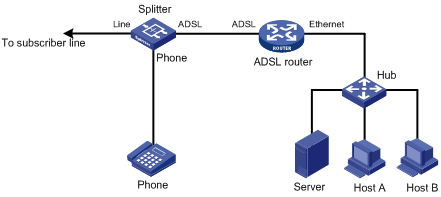
For a typical network topology for devices with ADSL interfaces, see Figure 1. Make sure you use standard twisted pairs and correctly connect the cables when you connect ADSL interfaces.
Configuring basic settings of an ADSL interface
1. Enter system view.
system-view
2. Enter ADSL interface view.
interface atm interface-number
3. (Optional.) Configure the interface description.
description text
By default, the description is interface-name Interface.
4. Activate the interface.
activate
By default, the interface is activated.
5. Configure the standard for an ADSL interface.
¡ Configure the standard for an ATM ADSL 2+ interface.
adsl standard { auto | g9923 | g9925 | gdmt | glite | t1413 }
By default, the standard for an ADSL interface is auto-negotiation.
The standard takes effect when you re-activate the interface by using either the shutdown and undo shutdown commands or the activate and undo activate commands.
6. Configure the transmission power attenuation for the ADSL interface.
adsl tx-attenuation attenuation
By default, the transmission power attenuation is 0, which means no attenuation.
7. (Optional.) Configure the expected bandwidth for the interface.
bandwidth bandwidth-value
By default, the expected bandwidth (in kbps) is calculated by using the following formula: Interface baud rate/1000.
The expected bandwidth is an informational parameter used only by higher-layer protocols for calculation. You cannot adjust the actual bandwidth of an interface by using this command.
8. Bring up the interface.
undo shutdown
By default, the interface is up.
Configuring the MTU for an ADSL interface
Restrictions and guidelines
The MTU setting affects the assembly and fragmentation of IP packets.
Procedure
1. Enter system view.
system-view
2. Enter ADSL interface view.
interface atm interface-number
3. Set the MTU.
mtu size
The default setting is 1500 bytes.
Restoring the default settings for an ADSL interface
Restrictions and guidelines
This feature might interrupt ongoing network services. Make sure you are fully aware of the impact of this feature when you use it on a live network.
This feature might fail to restore the default settings for some commands because of command dependencies or system restrictions. You can use the display this command in interface view to check for these commands and perform their undo forms or follow the command reference to restore their default settings. If your restoration attempt still fails, follow the error message to resolve the problem.
Procedure
1. Enter system view.
system-view
2. Enter ADSL interface view.
interface atm interface-number
3. Restore the default settings for the interface.
default
Configuring a G.SHDSL interface
About G.SHDSL interfaces
G.SHDSL is a symmetric transmission technology that implements high-speed data transmission over the twisted-pair copper wire by using unused high frequency ranges with a different modulation method.
The transmission speed of G.SHDSL is susceptible to transmission distance and line quality. An increased transmission distance means decreased line quality and transmission rate. Decreased transmission distance means increased line quality and transmission rate. When setting up a link, G. SHDSL can automatically tune the speed taking into consideration the actual line conditions such as distance and noise.
For a typical network topology for devices with G.SHDSL interfaces, see Figure 1.
Configuring basic settings of a G.SHDSL interface
1. Enter system view.
system-view
2. Enter G.SHDSL interface view.
interface atm interface-number
3. (Optional.) Configure the interface description.
description text
By default, the description is interface-name Interface.
4. Activate the interface.
activate
By default, the interface is activated.
5. Configure operating mode for the interface.
shdsl mode { co | cpe }
By default, the operating mode is CPE.
For a back-to-back connection, set one end to CO mode and the other end to CPE mode.
6. Configure the capacity type for the interface.
shdsl capability { auto | g-shdsl | g-shdsl-bis }
By default:
¡ auto is adopted in CPE mode.
¡ g-shdsl-bis is adopted in CO mode.
Interfaces on the two ends must be configured with the same capacity type.
7. (Optional.) Configure the expected bandwidth for the interface.
bandwidth bandwidth-value
By default, the expected bandwidth (in kbps) is calculated by using the following formula: Interface baud rate/1000.
The expected bandwidth is an informational parameter used only by higher-layer protocols for calculation. You cannot adjust the actual bandwidth of an interface by using this command.
8. Bring up the interface.
undo shutdown
By default, the interface is up.
As a best practice, shut down the unused G.SHDSL interfaces to save system resources.
Configuring the Annex standard for a G.SHDSL interface
About Annex standard
A link with different standard types at two ends cannot be activated.
Both Annex A and Annex B are G.991.2 standards. Annex A is dominant in North America and Annex B is dominant in Europe. When you set the annex standard, consider the standard used in your region.
Procedure
1. Enter system view.
system-view
2. Enter G.SHDSL interface view.
interface atm interface-number
3. Configure the Annex standard for the interface.
shdsl annex { a | b }
By default, Annex b is adopted.
Configuring the connection mode and single-pair interface rate for a G.SHDSL interface
About connection mode and single-pair interface rate
Based on the maximum wire pairs supported on an interface, the G.SHDSL interfaces include the following types:
· ATM SHDSL_4WIRE—Four-wire G.SHDSL (two pairs).
· ATM SHDSL_8WIRE_BIS—Eight-wire G.SHDSL.BIS (four pairs).
G.SHDSL.BIS incorporates the functions of G.SHDSL, supports four wire pairs, and enhances the maximum single-pair negotiation rate from 2312 kbps to 5696 kbps.
On an interface supporting multiple wire pairs, you can configure the number of wire pairs based on the interface rate.
Restrictions and guidelines
The operating mode of the local wire pairs must be consistent with the operating mode of the CO equipment.
Procedure
1. Enter system view.
system-view
2. Enter G.SHDSL interface view.
interface atm interface-number
3. Configure the connection mode for the interface.
¡ Configure the connection mode for four-wire G.SHDSL interfaces.
shdsl wire { 2 | 4-auto-enhanced | 4-enhanced | 4-standard }
By default, a four-wire G.SHDSL interface operates in four-wire enhanced mode.
¡ Configure the connection mode for eight-wire G.SHDSL.BIS interface.
shdsl wire { 2 | 4-enhanced | 4-standard | 6 | 8 | auto }
By default, an eight-wire G.SHDSL.BIS interface operates in eight-wire mode.
4. Configure the single-pair interface rate for the interface.
shdsl rate { rate | auto }
By default:
¡ For eight-wire G.SHDSL.BIS interfaces, the single-pair interface rate is automatically negotiated.
¡ For four-wire G.SHDSL interfaces, the single-pair interface rate is automatically negotiated in two-wire mode. It is 2312 kbps in non-two-wire modes (the four-wire interface rate is 4624 kbps).
Configuring an SNR target margin for a G.SHDSL interface
About configuring an SNR margin
Configuring an signal-to-noise ratio (SNR) margin can affect the maximum rate of the line. When the line condition is good, you can set a small margin to obtain higher rates. When the line is noisy, a small margin might cause disconnections.
Procedure
1. Enter system view.
system-view
2. Enter G.SHDSL interface view.
interface atm interface-number
3. Configure an SNR target margin.
shdsl snr-margin [ current current-margin-value ] [ snext snext-margin-value ]
By default, current-margin-value is 2 and snext-margin-value is 0.
Configuring the PSD mode for a G.SHDSL interface
About PSD mode
The power spectral density (PSD) is the amount of power per unit (density) of frequency (spectral) as a function of the frequency. The PSD describes how the power of a time series is distributed with frequency.
In symmetric mode, G.SHDSL interfaces on the CO and CPE are configured with the same PSD. In asymmetric mode, G.SHDSL interfaces on the CO and CPE are configured with different PSDs.
Procedure
1. Enter system view.
system-view
2. Enter G.SHDSL interface view.
interface atm interface-number
3. Configure the PSD mode for the interface.
shdsl psd { asymmetry | symmetry }
By default, the PSD mode of the interface is symmetric.
Tuning the transmission power for a G.SHDSL interface
About tuning the transmission power
An EFM interface automatically tunes its transmission power according to the line noise to ensure an appropriate signal-to-noise ratio. When the line noise is known or the automatically tuned value is inaccurate, use this feature to tune the transmission power manually.
Procedure
1. Enter system view.
system-view
2. Enter G.SHDSL interface view.
interface atm interface-number
3. Tune the transmission power.
shdsl pbo { value | auto }
By default, the interface automatically tunes its transmission power.
Configuring the PAM constellation for a G.SHDSL interface
About PAM constellation
The pulse amplitude modulation (PAM) is a constellation-like coding format of digital lines.
Use this feature to configure the digital signal modulation mode for PHY chips.
Procedure
1. Enter system view.
system-view
2. Enter G.SHDSL interface view.
interface atm interface-number
3. Configure the PAM constellation.
shdsl pam { 16 | 32 | auto }
By default, the interface automatically selects its PAM.
Configuring SHDSL line probing for a G.SHDSL interface
About SHDSL line probing
With SHDSL line probing enabled, the system performs SHDSL line probing to find the optimal data transmission rate during line activation.
With SHDSL line probing disabled, the system chooses the highest data transmission rate from the data transmission rates supported by both the CPE and CO. The amount of time available for activating the SHDSL lines is reduced because the line rate adaptation process is skipped.
Procedure
1. Enter system view.
system-view
2. Enter G.SHDSL interface view.
interface atm interface-number
3. Enable SHDSL line probing.
shdsl line-probing enable
By default, SHDSL line probing is enabled.
Configuring the MTU for a G.SHDSL interface
Restrictions and guidelines
The MTU setting affects the assembly and fragmentation of IP packets.
Procedure
1. Enter system view.
system-view
2. Enter G.SHDSL interface view.
interface atm interface-number
3. Set the MTU.
mtu size
The default setting is 1500 bytes.
Restoring the default settings for a G.SHDSL interface
Restrictions and guidelines
This feature might interrupt ongoing network services. Make sure you are fully aware of the impact of this feature when you use it on a live network.
This feature might fail to restore the default settings for some commands because of command dependencies or system restrictions. You can use the display this command in interface view to check for these commands and perform their undo forms or follow the command reference to restore their default settings. If your restoration attempt still fails, follow the error message to resolve the problem.
Procedure
1. Enter system view.
system-view
2. Enter G.SHDSL interface view.
interface atm interface-number
3. Restore the default settings for the interface.
default
Configuring an ATM subinterface
About ATM subinterfaces
An ATM subinterface supports the same network layer functions as an ATM interface. The network layers of different ATM subinterfaces are independent of each other. You can configure different Layer 3 services for ATM subinterfaces, such as IP services and MPLS services. To enable an ATM interface to support multiple Layer 3 services, create multiple subinterfaces for the interface.
The rate of an ATM subinterface depends on the rates of the PVCs or PVC-groups configured on the subinterfaces.
Configuring basic settings of an ATM subinterface interface
1. Enter system view.
system-view
2. Create an ATM subinterface and enter its view.
interface atm interface-number.subnumber [ p2mp | p2p ]
3. (Optional.) Configure the subinterface description.
description text
By default, the description is interface-name Interface.
4. (Optional.) Configure the expected bandwidth for the subinterface.
bandwidth bandwidth-value
By default, the expected bandwidth (in kbps) is calculated by using the following formula: Interface baud rate/1000.
The expected bandwidth is an informational parameter used only by higher-layer protocols for calculation. You cannot adjust the actual bandwidth of an interface by using this command.
5. Bring up the subinterface.
undo shutdown
By default, the subinterface is up.
Configuring the MTU for an ATM subinterface
Restrictions and guidelines
The MTU setting affects the assembly and fragmentation of IP packets.
Procedure
1. Enter system view.
system-view
2. Enter ATM subinterface view.
interface atm interface-number.subnumber
3. Set the MTU.
mtu size
The default setting is 1500 bytes.
Restoring the default settings for an ATM subinterface
Restrictions and guidelines
This feature might interrupt ongoing network services. Make sure you are fully aware of the impact of this feature when you use it on a live network.
This feature might fail to restore the default settings for some commands because of command dependencies or system restrictions. You can use the display this command in interface view to check for these commands and perform their undo forms or follow the command reference to restore their default settings. If your restoration attempt still fails, follow the error message to resolve the problem.
Procedure
1. Enter system view.
system-view
2. Enter ATM subinterface view.
interface atm interface-number.subnumber
3. Restore the default settings for the interface.
default
Configuring an EFM interface
About EFM interfaces
Ethernet First Mile (EFM) interfaces receive and transmit Ethernet frames over ATM physical links and use the Ethernet protocol suite. They can transmit Ethernet frames over legacy DSL lines and achieve all-Ethernet access. By implementing stable, high-speed Ethernet packet transmission over telephone lines, EFM extends the transmission distance of Ethernet from 100 meters to 1500 meters. With EFM interfaces, the Ethernet technologies can be deployed on the access networks of telecom users, which improves network performance and lowers device and operation costs.
No dedicated but multi-purpose EFM cards are available. Switch the operating mode of an interface card as needed.
This section covers only the physical configurations of the EFM interface. You can also configure ARP, DHCP, IP address, and firewall on an EFM interface.
Configuring basic settings of an EFM interface
1. Enter system view.
system-view
2. Enter EFM interface view.
interface efm interface-number
3. (Optional.) Configure the interface description.
description text
By default, the description is interface-name Interface.
4. Configure the operating mode for the interface.
shdsl mode { co | cpe }
By default, the operating mode of the interface is CPE.
5. (Optional.) Configure the expected bandwidth for the interface.
bandwidth bandwidth-value
By default, the expected bandwidth (in kbps) is calculated by using the following formula: Interface baud rate/1000.
The expected bandwidth is an informational parameter used only by higher-layer protocols for calculation. You cannot adjust the actual bandwidth of an interface by using this command.
6. Bring up the interface.
undo shutdown
By default, the interface is up.
Configuring the Annex standard for an EFM interface
About Annex standard
A link with different standard types at two ends cannot be activated.
Both Annex A and Annex B are G.991.2 standards. Annex A is dominant in North America and Annex B is dominant in Europe. When you set the annex standard, consider the standard used in your region.
Procedure
1. Enter system view.
system-view
2. Enter EFM interface view.
interface efm interface-number
3. Configure the Annex standard for the interface.
shdsl annex { a | b }
By default, Annex b is adopted.
Configuring the connection mode and single-pair interface rate for an EFM interface
About connection mode and single-pair interface rate
EFM interfaces include only one type, EFM SHDSL_8WIRE_BIS, which represents eight-wire G.SHDSL.BIS.
Restrictions and guidelines
The operating mode of the local wire pairs must be consistent with the operating mode of the CO equipment.
Procedure
1. Enter system view.
system-view
2. Enter EFM interface view.
interface efm interface-number
3. Configure the connection mode for the interface.
¡ For an eight-wire G.SHDSL.BIS interface:
shdsl wire { 2 | 4-enhanced | 4-standard | 6 | 8 | auto }
By default, an eight-wire G.SHDSL.BIS interface operates in eight-wire mode.
4. Configure the single-pair interface rate for the interface.
shdsl rate { rate | auto }
By default, the single-pair interface rate for an eight-wire G.SHDSL.BIS interface is automatically negotiated.
Configuring an SNR target margin for an EFM interface
About configuring an SNR margin
Configuring an signal-to-noise ratio (SNR) margin can affect the maximum rate of the line. When the line condition is good, you can set a small margin to obtain higher rates. When the line is noisy, a small margin might cause disconnections.
Procedure
1. Enter system view.
system-view
2. Enter EFM interface view.
interface efm interface-number
3. Configure an SNR target margin.
shdsl snr-margin [ current current-margin-value ] [ snext snext-margin-value ]
By default, current-margin-value is 2 and snext-margin-value is 0.
Configuring the PSD mode for an EFM interface
About PSD mode
The PSD is the amount of power per unit (density) of frequency (spectral) as a function of the frequency. The PSD describes how the power of a time series is distributed with frequency.
In symmetric mode, EFM interfaces on the CO and CPE are configured with the same PSD. In asymmetric mode, EFM interfaces on the CO and CPE are configured with different PSDs.
Procedure
1. Enter system view.
system-view
2. Enter EFM interface view.
interface efm interface-number
3. Configure the PSD mode for the interface.
shdsl psd { asymmetry | symmetry }
By default, the PSD mode of the interface is symmetric.
Tuning the transmission power for an EFM interface
About tuning the transmission power
An EFM interface automatically tunes its transmission power according to the line noise to ensure an appropriate signal-to-noise ratio. When the line noise is known or the automatically tuned value is inaccurate, use this feature to tune the transmission power manually.
Procedure
1. Enter system view.
system-view
2. Enter EFM interface view.
interface efm interface-number
3. Tune the transmission power.
shdsl pbo { value | auto }
By default, the interface automatically tunes its transmission power.
Configuring the PAM constellation for an EFM interface
About PAM constellation
PAM is a constellation-like coding format of digital lines.
Use this feature to configure the digital signal modulation mode for PHY chips.
Procedure
1. Enter system view.
system-view
2. Enter EFM interface view.
interface efm interface-number
3. Configure the PAM constellation.
shdsl pam { 16 | 32 | auto }
By default, the interface automatically selects its PAM.
Configuring SHDSL line probing for an EFM interface
About SHDSL line probing
With SHDSL line probing enabled, the system performs SHDSL line probing to find the optimal data transmission rate during line activation.
With SHDSL line probing disabled, the system chooses the highest data transmission rate from the data transmission rates supported by both the CPE and CO. The amount of time available for activating the SHDSL lines is reduced because the line rate adaptation process is skipped.
Procedure
1. Enter system view.
system-view
2. Enter EFM interface view.
interface efm interface-number
3. Enable SHDSL line probing.
shdsl line-probing enable
By default, SHDSL line probing is enabled.
Configuring the MTU for an EFM interface
Restrictions and guidelines
The MTU setting affects the assembly and fragmentation of IP packets.
Procedure
1. Enter system view.
system-view
2. Enter EFM interface view.
interface efm interface-number
3. Set the MTU.
mtu size
The default setting is 1500 bytes.
Restoring the default settings for an EFM interface
Restrictions and guidelines
This feature might interrupt ongoing network services. Make sure you are fully aware of the impact of this feature when you use it on a live network.
This feature might fail to restore the default settings for some commands because of command dependencies or system restrictions. You can use the display this command in interface view to check for these commands and perform their undo forms or follow the command reference to restore their default settings. If your restoration attempt still fails, follow the error message to resolve the problem.
Procedure
1. Enter system view.
system-view
2. Enter EFM interface view.
interface efm interface-number
3. Restore the default settings for the interface.
default
Configuring an EFM subinterface
Configuring basic settings of an EFM subinterface
1. Enter system view.
system-view
2. Create an EFM subinterface and enter its view.
interface efm interface-number.subnumber
3. (Optional.) Configure the subinterface description.
description text
By default, the description is interface-name Interface.
4. (Optional.) Configure the expected bandwidth for the subinterface.
bandwidth bandwidth-value
By default, the expected bandwidth (in kbps) is calculated by using the following formula: Interface baud rate/1000.
The expected bandwidth is an informational parameter used only by higher-layer protocols for calculation. You cannot adjust the actual bandwidth of an interface by using this command.
5. Bring up the subinterface.
undo shutdown
By default, the subinterface is up.
Configuring the MTU for an EFM subinterface
Restrictions and guidelines
The MTU setting affects the assembly and fragmentation of IP packets.
Procedure
1. Enter system view.
system-view
2. Enter EFM subinterface view.
interface efm interface-number.subnumber
3. Set the MTU.
mtu size
The default setting is 1500 bytes.
Restoring the default settings for an EFM subinterface
Restrictions and guidelines
This feature might interrupt ongoing network services. Make sure you are fully aware of the impact of this feature when you use it on a live network.
This feature might fail to restore the default settings for some commands because of command dependencies or system restrictions. You can use the display this command in interface view to check for these commands and perform their undo forms or follow the command reference to restore their default settings. If your restoration attempt still fails, follow the error message to resolve the problem.
Procedure
1. Enter system view.
system-view
2. Enter EFM subinterface view.
interface efm interface-number.subnumber
3. Restore the default settings for the interface.
default
Display and maintenance commands for ATM interfaces
Execute display commands in any view and reset commands in user view.
|
Task |
Command |
|
Display interface traffic statistics. |
display counters { inbound | outbound } interface [ atm [ interface-number ] ] |
|
Display traffic rate statistics for interfaces in up state for the most recent statistics interval. |
display counters rate { inbound | outbound } interface [ atm [ interface-number ] ] |
|
Display DSL configuration information. |
display dsl configuration interface atm interface-number |
|
Display DSL status information. |
display dsl status interface atm interface-number |
|
Display DSL version information and available capabilities. |
display dsl version interface atm interface-number |
|
Display ATM interface information. |
display interface [ atm [ interface-number ] ] [ brief [ description | down ] ] |
|
Display EFM interface information. |
display interface [ efm [ interface-number ] ] [ brief [ description | down ] ] |
|
Clear the statistics for an interface. |
reset counters interface [ atm [ interface-number ] ] |
Troubleshooting ATM interfaces
Interface state error
Symptom
The ATM interface state is down.
Solution
To resolve the problem:
1. Verify that the Rx and Tx ends of the optical fiber are correctly connected.
2. If the two devices are connected back-to-back, verify that the clock mode is set to master on one interface, and to slave on the other interface. The default clock mode is slave. To set the clock mode to master, use the clock master command.
3. If the problem persists, contact H3C Support.
Frequent packet dropping, CRC check errors, and interface state errors
Symptom
Two devices connecting back-to-back can ping each other successfully. Frequent packet dropping and CRC errors occur, and the interface state flaps between up and down.
Solution
To resolve the problem:
1. Verify that the ATM interfaces of the two sides are of the same type, for example, multimode fiber interfaces or single-mode fiber interfaces.
If a multimode fiber interface and a single-mode fiber interface are directly connected, they can communicate in most cases. However, frequent packet dropping, CRC errors, and interface state errors might occur.
2. If the problem persists, contact H3C Support.
Incorrect DSL interface line operations
Symptom
The DSL interface cannot transmit or receive data, or high bit-error rate or high interference occurs during data transmission.
Solution
To resolve the problem:
1. Locate the faulty node.
2. Read the LEDs for the DSL interface card.
When the DSL line is training, the LINK LED blinks. After the activation succeeds, the LINK LED which should otherwise be OFF lights and stays ON. The Activity LED blinks when data is being transmitted on the line.
3. If line activation attempts always fail, verify that the line is connected securely and functioning correctly.
4. Display the DSL state information by using the display dsl status command.
5. Use the debugging physical command to view details about activation, such as issuing of the activate command, activation timeout, training process, and activation success.
6. If the bit error rate is high or interference occurs too often, shut down and then bring up the interface by using the shutdown and undo shutdown commands. You can also reboot the device and reconnect the line. If the problem persists, perform an overall line condition and environment check.
7. If the problem persists, contact H3C Support.
