- Table of Contents
- Related Documents
-
| Title | Size | Download |
|---|---|---|
| 03-WAN interface configuration | 258.71 KB |
Restrictions: Hardware compatibility with WAN interfaces
Configuring common WAN interface settings
Configuring a serial interface
Configuring an asynchronous serial interface
Configuring a synchronous serial interface
Enabling local loopback on a serial interface
Configuring a serial subinterface
Display and maintenance commands for serial interfaces
Configuring basic settings of an AM interface
Enabling local loopback on an AM interface
Display and maintenance commands for AM interfaces
Display and maintenance commands for FCM interfaces
Configuring an ISDN BRI interface
Enabling local loopback on an ISDN BRI interface
Display and maintenance commands for ISDN BRI interfaces
Configuring a CE1/PRI interface
Configuring unchannelized mode for a CE1/PRI interface
Configuring channelized mode for a CE1/PRI interface
Configuring other CE1/PRI interface parameters
Enabling local loopback on a CE1/PRI interface
Display and maintenance commands for CE1/PRI interfaces
Configuring a CT1/PRI interface
Configuring a CT1/PRI interface in CT1 mode
Configuring a CT1/PRI interface in PRI mode
Configuring other CT1/PRI interface parameters
Enabling local loopback on a CT1/PRI interface
Display and maintenance commands for CT1/PRI interfaces
Configuring an E1-F interface in framed mode
Configuring an E1-F interface in unframed mode
Configuring other E1-F interface parameters
Enabling local loopback on an E1-F interface
Display and maintenance commands for E1-F interfaces
Configuring common T1-F interface settings
Enabling local loopback on a T1-F interface
Display and maintenance commands for T1-F interfaces
Configuring a CE3 interface in E3 mode
Configuring a CE3 interface in CE3 mode
Enabling local loopback on a CE3 interface
Display and maintenance commands for CE3 interfaces
Configuring a CT3 interface in T3 mode
Configuring a CT3 interface in CT3 mode
Enabling local loopback on a CT3 interface
Configuring WAN interfaces
About WAN interfaces
This chapter describes how to configure the following types of WAN interfaces:
· Asynchronous serial interface.
· Synchronous serial interface.
· Synchronous/asynchronous serial interface.
· AM interface.
· FCM interface.
· ISDN BRI interface.
· CE1/PRI interface.
· CT1/PRI interface.
· E1-F interface.
· T1-F interface.
· CE3 interface.
· CT3 interface.
· ATM interface.
For more information about ATM interfaces, see "Configuring ATM interfaces."
Restrictions: Hardware compatibility with WAN interfaces
Commands in this chapter are supported only when the device has related interfaces. For the interfaces that the device has, see the installation guide and interface module manuals.
Configuring common WAN interface settings
About configuring common WAN interface settings
This section only describes the common properties configuration for WAN interfaces.
Procedure
1. Enter system view.
system-view
2. Enter an interface view.
¡ Enter asynchronous serial interface view.
interface async interface-number
¡ Enter synchronous serial/ E1-F/T1-F interface view.
interface serial interface-number
¡ Enter serial subinterface view.
interface serial interface-number.subnumber [ p2mp | p2p ]
¡ Enter AM interface view.
interface analogmodem { interface-number | interface-number:15 }
¡ Enter FCM interface view.
interface fcm { interface-number | interface-number:15 }
¡ Enter ISDN BRI interface view.
interface bri interface-number
¡ Enter CE1/PRI interface view.
controller e1 interface-number
¡ Enter CT1/PRI interface view.
controller t1 interface-number
¡ Enter CE3 interface view.
controller e3 interface-number
¡ Enter CT3 interface view.
controller t3 interface-number
3. Configure the interface description.
description text
By default, the description of an asynchronous serial interface is interface name Interface, for example, Serial2/1/0 Interface.
4. Set the expected bandwidth for the interface.
bandwidth bandwidth-value
By default, the expected bandwidth (in kbps) is the interface baud rate divided by 1000.
The expected bandwidth is an informational parameter used only by higher-layer protocols for calculation. You cannot adjust the actual bandwidth of an interface by using this command.
Interfaces that support this feature include AM interfaces, E1-F/T1-F interfaces, FCM interfaces, ISDN BRI interfaces, and Serial interfaces/subinterfaces.
5. Configure the keepalive interval and retry limit.
¡ Set the keepalive interval.
timer-hold seconds
The default setting is 10 seconds.
¡ Set the keepalive retry limit.
timer-hold retry retries
The default setting is 5.
Interfaces that support this feature include AM interfaces, E1-F/T1-F interfaces, FCM interfaces, ISDN BRI interfaces, and Serial interfaces.
6. Set the MTU.
mtu size
The default setting is 1500 bytes.
Interfaces that support this feature include AM interfaces, E1-F/T1-F interfaces, FCM interfaces, ISDN BRI interfaces, and Serial interfaces/subinterfaces.
7. Bring up the interface.
undo shutdown
By default, an interface is up.
Configuring a serial interface
About serial interfaces
Serial interfaces include asynchronous serial interfaces and synchronous serial interfaces.
Asynchronous serial interface
The following types of asynchronous serial interfaces are available:
· Synchronous/asynchronous serial interface operating in asynchronous mode. The interface type name is Serial.
· Dedicated asynchronous serial interface. The interface type name is Async.
You can connect a modem or ISDN terminal adapter to an asynchronous serial interface for dial-up connection.
An asynchronous serial interface can operate in protocol or flow mode.
· Protocol mode—Data is transmitted in packets. The link layer protocol can only be PPP. The network layer protocol is typically IP.
· Flow mode—Data is transmitted as character flows. This mode is typically used in human-machine interaction scenarios such as dial-up access. After the physical connection is established, you can send commands to set up a link with the asynchronous serial interface, and then configure the device.
Synchronous serial interface
Synchronous serial interfaces refer to synchronous/asynchronous serial interfaces operating in synchronous mode. They provide serial communication channels for synchronous data transmission. The interface type name is Serial.
A synchronous serial interface operates in DCE or DTE mode. Two directly connected synchronous serial interfaces must operate in different modes.
· In DCE mode, the interface provides timing for synchronization and sets the baud rate.
· In DTE mode, the interface accepts the timing signal and baud rate from the DCE.
The synchronous serial interfaces on the device typically operate as DTE.
You can connect a synchronous interface to various types of cables, including V.24, V.35, X.21, RS449, and RS530. Typically, the device can automatically recognize the cable type and select electrical properties.
The synchronous serial interface supports the following protocols:
· Data link layer protocols, such as PPP, HDLC, LAPB, and Frame Relay.
· Network layer protocols, such as IP.
Configuring an asynchronous serial interface
About asynchronous serial interfaces
This section only describes the interface properties configuration. Depending on the network requirements, you might also need to configure PPP, DDR, IP address, firewall, and interface backup.
Procedure
1. Enter system view.
system-view
2. Enter a serial interface view.
¡ Enter asynchronous serial interface view.
interface async interface-number
¡ Enter synchronous serial interface view.
interface serial interface-number
3. Configure a synchronous or asynchronous serial interface to operate as an asynchronous serial interface.
physical-mode async
By default, a synchronous or asynchronous serial interface operates as a synchronous serial interface.
Skip this step if the interface is an asynchronous interface.
4. Set the link layer protocol.
link-protocol { fr | hdlc | mfr | ppp | stlp }
The default is PPP.
5. Set the operating mode.
async mode { flow | protocol }
The default is the protocol mode.
6. Disable level detection.
undo detect dsr-dtr
By default, level detection is enabled.
7. (Optional.) Eliminate the pulses with a width less than 3.472 μs.
eliminate-pulse
By default, the pulses with a width less than 1.472 μs are eliminated.
Use this command to improve the signal reliability in an environment with intensive line interference.
8. Set the MRU for an interface operating in flow mode.
phy-mru mrusize
The default MRU is 1700 bytes.
Configuring a synchronous serial interface
About synchronous serial interfaces
This section only describes the interface properties configuration. Depending on the network requirements, you might also need to configure the data link layer protocol, DDR, IP address, firewall, and interface backup.
Procedure
1. Enter system view.
system-view
2. Enter synchronous serial interface view.
interface serial interface-number
3. Configure a synchronous or asynchronous serial interface to operate as a synchronous serial interface.
physical-mode sync
By default, a synchronous or asynchronous serial interface operates as a synchronous serial interface.
4. Set the link layer protocol.
link-protocol { fr | hdlc | mfr | ppp | stlp }
The default is PPP.
5. Set the digital signal coding format.
code { nrz | nrzi }
The default is non-return-to-zero (NRZ).
6. Set the clock selection mode.
¡ On DTE side:
clock { dteclk1 | dteclk2 | dteclk3 | dteclk4 | dteclk5 | dteclkauto }
¡ On DCE side:
clock { dceclk1 | dceclk2 | dceclk3 }
The default is dceclk1 for the DCE side and dteclk1 for the DTE side.
7. Set transmit-clock or receive-clock signal inversion on the DTE side.
invert { transmit-clock | receive-clock }
By default, clock signal inversion is disabled.
8. Set the line idle-code.
idle-code { 7e | ff }
The default is 0x7E.
9. Enable RTS signal reverse.
reverse-rts
By default, RTS signal reverse is disabled.
When this command is configured, the remote end is not allowed to send data while the local end is sending data.
Use this command only for debugging purposes.
10. Configure interface properties.
¡ Set the number of interframe filling tags.
itf number number
The default is four.
¡ Set the baud rate on DCE side.
baudrate baudrate
The default is 64000 bps.
¡ Set the baud rate on DTE side.
virtualbaudrate virtualbaudrate
The default is 64000 bps.
11. Configure line detection settings.
¡ Enable level detection.
detect dsr-dtr
By default, level detection is enabled.
¡ Enable data carrier detection (DCD).
detect dcd
By default, DCD is enabled.
¡ Set the CRC mode.
crc { 16 | 32 | none }
The default is 16-bit CRC.
¡ Initiate a loopback test.
loopback-test [ -c count | -p { pattern | special { ascending | descending | random } } | -s packetsize | -t timeout ] * interface interface-type interface-number
By default, no loopback test is performed on an interface.
This command is available only on synchronous serial interfaces that are created for E1, T1, E1-F, and T1-F interfaces.
Enabling local loopback on a serial interface
About loopback
Perform this task to determine whether a serial link works correctly. This feature tests the device where the serial interface resides. The serial interface sends outgoing packets back to the local device. If the device fails to receive the packets, the device fails.
Restrictions and guidelines
After you enable this feature on a serial interface, the interface does not forward data traffic.
Procedure
1. Enter system view.
system-view
2. Enter a serial interface view.
¡ Enter asynchronous serial interface view.
interface async interface-number
¡ Enter synchronous serial interface view.
interface serial interface-number
3. Enable local loopback.
loopback
By default, local loopback is disabled.
Configuring a serial subinterface
1. Enter system view.
system-view
2. Create a serial subinterface and enter its view.
interface serial interface-number.subnumber [ p2mp | p2p ]
3. Configure a serial subinterface.
See "Configuring common WAN interface settings."
Display and maintenance commands for serial interfaces
Execute display commands in any view and reset commands in user view.
|
Task |
Command |
|
Display serial interface information. |
display interface serial [ interface-number ] [ brief [ description | down ] ] |
|
Display information about asynchronous serial interfaces. |
display interface async [ interface-number ] [ brief [ description | down ] |
|
Clear statistics for serial interfaces. |
reset counters interface serial [ interface-number ] |
|
Clear statistics for asynchronous serial interfaces. |
reset counters interface async [ interface-number ] |
Configuring an AM interface
About AM interfaces
The analog modem (AM) interface combines the functionality of the asynchronous serial interface and analog modem. The AM interface supports most of the commands available on asynchronous serial interfaces and modems. When you configure an AM interface, you can treat it as a special asynchronous serial interface.
AM interfaces provide dial-in and dial-out services for analog dial-up users.
The AM interface can provide the following maximum downstream and upstream rates:
· If the peer (typically an ISP) uses a digital modem, the AM interface can use the V.90 Modem standard to set up connections. The maximum downstream rate is 56 kbps, and the maximum upstream rate is 33.6 kbps.
· If the peer (typically a subscriber) uses an analog modem (or an AM interface), the AM interface can use the V.34 Modem standard to set up connections. The maximum downstream and upstream rates are both 33.6 kbps.
This section only describes the interface properties configuration. Depending on the network requirements, you might also need to configure PPP, DDR, IP address, firewall, and interface backup.
Restrictions and guidelines
The AM interface does not support the modem auto-answer or baudrate command.
To set the baud rate for an AM interface, use the speed command in user line view. For more information, see Fundamentals Configuration Guide.
Configuring basic settings of an AM interface
1. Enter system view.
system-view
2. Enter AM interface view.
interface analogmodem { interface-number | interface-number:15 }
3. Set the coding format of the modem.
country-code area-name
The default is united-states.
For more information about this command, see Layer 2—WAN Command Reference.
4. Set the operating mode.
async-mode { flow | protocol }
By default, an AM interface operates in flow mode.
When an AM interface is operating in flow mode, no data link layer protocol is available. When operating in protocol mode, the AM interface uses PPP as the data link layer protocol.
5. Eliminate the pulses with a width less than 3.472 μs.
eliminate-pulse
By default, the pulses with a width less than 1.472 μs are eliminated.
This command applies to 8ASE and 16ASE interface cards.
Use this command to improve the signal reliability in an environment with intensive line interference.
6. Set the MRU for an AM interface operating in flow mode.
phy-mru mrusize
The default MRU is 1700 bytes.
Enabling local loopback on an AM interface
About loopback
Perform this task to determine whether an AM link works correctly. This feature tests the device where the AM interface resides. The AM interface sends outgoing packets back to the local device. If the device fails to receive the packets, the device fails.
Restrictions and guidelines
After you enable this feature on an AM interface, the interface does not forward data traffic.
Procedure
1. Enter system view.
system-view
2. Enter AM interface view.
interface analogmodem { interface-number | interface-number:15 }
3. Enable local loopback.
loopback
By default, local loopback is disabled.
Display and maintenance commands for AM interfaces
Execute display commands in any view and reset commands in user view.
|
Task |
Command |
|
Display AM interface information. |
display interface analogmodem [ interface-number ] [ brief [ description | down ] ] |
|
Clear statistics for AM interfaces. |
reset counters interface analogmodem [ interface-number ] |
Configuring an FCM interface
About FCM interfaces
Fast Connect Modem (FCM) interfaces are dedicated for POS access. They use CCITT V.22 or CCITT V.29 to complete POS dial-up and access in a short time.
An FCM interface has the following features:
· Achieves reliable ring detection and off-hook in a short time.
· Compatible with standard protocols to interoperate with POS devices of other mainstream vendors.
· Able to respond to POS calls and access the POS device.
FCM interfaces apply only to POS terminal access. To use FCM interfaces, you need to configure POS terminal access parameters. For more information, see Terminal Access Configuration Guide.
Procedure
1. Enter system view.
system-view
2. Enter FCM interface view.
interface fcm { interface-number | interface-number:15 }
3. Set the PCM for the FCM interface.
pcm { a-law | u-law }
The default is a-law.
Display and maintenance commands for FCM interfaces
Execute display commands in any view and reset commands in user view.
|
Task |
Command |
|
Display FCM interface information. |
display interface fcm [ interface-number ] [ brief [ description | down ] ] |
|
Clear statistics for FCM interfaces. |
reset counters interface fcm [ interface-number ] |
Configuring an ISDN BRI interface
About ISDN BRI interfaces
This section only describes the interface properties configuration. For more information about dial-up configuration, see Layer 2—WAN Access Configuration Guide.
ISDN provides all-digital terminal-to-terminal services and fulfills the fully digitized delivery of services integrating voice, data, graphics, and video.
ISDN implements digital transmission on a user loop and provides end-to-end digitization. As a standardized digital interface, ISDN BRI interface can forward digital and analog information.
The most commonly used ISDN standards include ITU-T I.430, Q.921, and Q.931 recommendations. All devices that meet ITU-T ISDN standards can access an ISDN network.
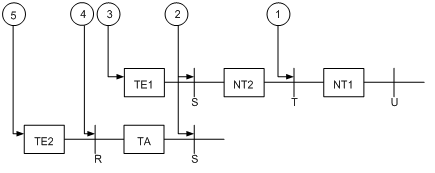
ITU-T I.411 standardizes the ISDN user-network interface and provides a reference configuration for ISDN access. As shown in Figure 1, the reference configuration contains the following elements:
· Function groups—Sets of functions required for accessing an ISDN network.
¡ Network terminal 1 (NT1)—Implements the functionality of the first layer in the OSI reference model, such as subscriber-line transmission, loop test, and D-channel competition.
¡ Network terminal 2 (NT2)—Implements the functionality of layers 1 through 3. NT2 is also known as the intelligent network terminal.
¡ Category-1 terminal equipment (TE1)—User equipment compliant with the ISDN interface provisions. TE1 is also known as the ISDN standard terminal. Digital phone-set is an example of TE1.
¡ Category-2 terminal equipment (TE2)—User equipment incompliant with the ISDN interface provisions. TE2 is also known as non-ISDN standard terminal equipment.
¡ Terminal adapter (TA)—Provides adaptation for TE2 to access a standard ISDN interface.
· Reference points—Points used to differentiate function groups.
¡ R—Reference point between a non-ISDN equipment and TA.
¡ S—Reference point between a user terminal and NT2.
¡ T—Reference point between NT1 and NT2.
¡ U—Reference point between NT1 and line terminal.
Figure 1 Referential ISDN user-network interface configuration
Prerequisites
Before you configure an ISDN BRI interface, verify the following items:
· Interface type (ISDN BRI U or ISDN BRI S/T) provided by your telecom service provider—You must identify this information before you purchase a router. You must perform this task because the UNI implementation of a service provider might deviate from ITU-T I.411.
· Availability of digital service—The router requires digital transmission. You must subscribe to the digital call service for an ISDN line.
· Connection type (point-to-point or point-to-multipoint)—Because ISDN supports semi-permanent connections, you can use an ISDN leased line to connect two permanent points. To connect more than two points, use a point-to-multipoint connection.
· Availability of the calling line identification function—This function can filter calling numbers on an ISDN line to block unauthorized users from the router.
Activating the BRI interface
1. Enter system view.
system-view
2. Enter ISDN BRI interface view.
interface bri interface-number
3. Activate the BRI interface.
activate
By default, a BRI interface is not activated.
By default, a BRI interface is active only when a call is present.
Enabling local loopback on an ISDN BRI interface
About loopback
Loopback is intended for testing only. Disable loopback when the interface is operating correctly.
Restrictions and guidelines
After you enable this feature on an ISDN BRI interface, the interface does not forward data traffic.
Procedure
1. Enter system view.
system-view
2. Enter ISDN BRI interface view.
interface bri interface-number
3. Enable local loopback.
loopback { b1 | b2 | both | remote }
By default, local loopback is disabled.
Display and maintenance commands for ISDN BRI interfaces
Execute display commands in any view and reset commands in user view.
|
Task |
Command |
|
Display information about ISDN BRI interfaces. |
display interface bri [ interface-number ] [ brief [ description | down ] ] |
|
Clear statistics for ISDN BRI interfaces. |
reset counters interface bri [ interface-number ] |
Configuring a CE1/PRI interface
About CE1/PRI interfaces
A CE1/PRI interface can operate in channelized or unchannelized mode:
· Unchannelized mode is also called E1 mode.
· Channelized modes include CE1 mode and PRI mode.
In CE1 or PRI mode, a CE1/PRI interface is physically divided into 32 timeslots numbered 0 to 31. Timeslot 0 is used to transmit synchronizing information.
E1 mode
For a CE1/PRI interface in E1 mode, the system automatically creates a serial interface named serial interface-number:0. This interface has the same logical features as a standard synchronous serial interface. You can configure the serial interface as described in "Configuring a synchronous serial interface."
CE1 mode
In CE1 mode, you can bundle all timeslots except timeslot 0 into a maximum of 31 channel sets.
· For each channel set, the system automatically creates a serial interface named serial interface-number:set-number. This interface has the same logical features as a standard synchronous serial interface. You can configure the serial interface as described in "Configuring a synchronous serial interface."
PRI mode
In PRI mode, timeslot 16 is used as the D channel to transmit signaling. You can bundle all timeslots except timeslots 0 and 16 to form a B channel, and then bundle the B channel and timeslot 16 into a PRI set. Only one PRI set can be bundled on a CE1/PRI interface.
CE1/PRI interfaces have six physical types. The system creates different interfaces when you bundle PRI sets on interfaces of different physical types, as shown in Table 1.
Table 1 Automatically created interfaces on CE1/PRI interfaces of different physical types
|
Physical type of CE1/PRI interfaces |
Automatically created interfaces for a PRI set |
|
PHY_E1 |
One serial interface (serial interface-number:15) |
|
PHY_VE1 |
· One serial interface (serial interface-number:15) · One voice interface (subscriber-line interface-number:15) |
|
PHY_DVE1 |
· One serial interface (serial interface-number:15) · One voice interface (subscriber-line interface-number:15) |
|
PHY_E1POS |
· One serial interface (serial interface-number:15) · One FCM interface (fcm interface-number:15) |
|
PHY_E1DM |
· One serial interface (serial interface-number:15) · One AM interface (analogmodem interface-number:15) |
|
PHY_E1POSDM |
· One serial interface (serial interface-number:15) · One FCM interface (fcm interface-number:15) · One AM interface (analogmodem interface-number:15) |
For information about configuring AM interfaces, see "Configuring an AM interface."
For information about configuring FCM interfaces, see "Configuring an FCM interface."
For information about configuring voice interfaces, see Voice Configuration Guide.
The created serial interface has the same logical features as an ISDN PRI interface. The interface supports the following settings:
· DDR.
· PPP and PPP authentication.
· IP addressing.
· Interface backup settings if you use the interface as a primary or backup interface.
· Firewall settings.
For more information about serial interface configuration, see "Configuring a serial interface."
A CE1/PRI interface can operate only in PRI mode if its physical type is PHY_E1POS, PHY_E1DM, or PHY_E1POSDM.
Configuring unchannelized mode for a CE1/PRI interface
Configuring a CE1/PRI interface in E1 mode
1. Enter system view.
system-view
2. Enter CE1/PRI interface view.
controller e1 interface-number
3. Configure the interface to operate in E1 mode.
using e1
By default, a CE1/PRI interface operates in channelized mode.
4. Enable alarm indication signal (AIS) detection.
detect-ais
By default, AIS detection is disabled.
5. Set other interface parameters.
See "Configuring other CE1/PRI interface parameters."
Configuring channelized mode for a CE1/PRI interface
Configuring a CE1/PRI interface in CE1 mode
1. Enter system view.
system-view
2. Enter CE1/PRI interface view.
controller e1 interface-number
3. Configure the interface to operate in channelized mode.
using ce1
By default, a CE1/PRI interface operates in channelized mode.
4. Bundle timeslots on the interface into a channel set.
channel-set set-number timeslot-list list
For each channel set, the system automatically creates a serial interface that has the same logical features as a standard synchronous serial interface. The serial interface name uses the serial interface-number:set-number format.
5. Set the framing format.
frame-format { crc4 | no-crc4 }
The default is no-CRC4.
A CE1/PRI interface in CE1 mode supports both CRC4 and no-CRC4 framing formats.
6. Enable RAI detection on the interface.
alarm-detect rai
By default, RAI detection is enabled on the interface.
7. Set other interface parameters.
See "Configuring other CE1/PRI interface parameters."
Configuring a CE1/PRI interface in PRI mode
1. Enter system view.
system-view
2. Enter CE1/PRI interface view.
controller e1 interface-number
3. Configure the interface to operate in channelized mode.
using ce1
By default, a CE1/PRI interface operates in channelized mode.
4. Set the interface to synchronous or asynchronous mode.
work-mode { async | sync }
By default, a CE1/PRI interface operates in synchronous mode.
This command is available only for CE1/PRI interfaces on the DHMIM-1E1POS1DM card. These interfaces can operate only in PRI mode because their physical type is PHY_E1POSDM.
5. Bundle timeslots on the interface into a PRI set.
pri-set [ timeslot-list list ]
6. Set other interface parameters.
See "Configuring other CE1/PRI interface parameters."
Configuring other CE1/PRI interface parameters
1. Enter system view.
system-view
2. Enter CE1/PRI interface view.
controller e1 interface-number
3. Set the line code format.
code { ami | hdb3 }
The default is high density bipolar 3 (HDB3).
4. Enable or disable user data inversion.
data-coding { inverted | normal }
By default, user data inversion is disabled.
5. Set the cable type.
cable { long | short }
The default cable setting is long mode.
6. Set the cable impedance.
cable-type { 75 | 120 }
By default, the cable impedance for a CE1/PRI interface is 75 ohm.
7. Set the clock mode.
clock { master | slave }
The default clock mode is slave, which is line clock.
8. Enable automatic clock mode change.
clock-change auto
By default, automatic clock mode change is disabled.
When automatic clock mode switchover is enabled, the interface automatically switches to the master clock mode when both of the following conditions exist:
¡ The interface uses the slave clock mode.
¡ The interface receives an alarm indication signal (AIS), loss of signal (LOS), or loss of frame (LOF) alarm.
After the alarm is cleared, the interface automatically switches back to the slave clock mode.
9. Set the line idle code type.
idle-code { 7e | ff }
The default is 0x7E.
10. Set the type and the number of interframe filling tags.
itf { number number | type { 7e | ff } }
By default:
¡ The type of the interframe filling tag is 0x7E.
¡ The number of interframe filling tags is four.
Enabling local loopback on a CE1/PRI interface
About loopback
Loopback is intended for testing only. Disable loopback when the interface is operating correctly.
Restrictions and guidelines
After you enable this feature on an interface, the interface does not forward data traffic.
Procedure
1. Enter system view.
system-view
2. Enter CE1/PRI interface view.
controller e1 interface-number
3. Enable local loopback.
loopback { local | payload | remote }
By default, local loopback is disabled.
Display and maintenance commands for CE1/PRI interfaces
Execute display commands in any view and reset commands in user view.
|
Task |
Command |
|
Display information about CE1/PRI interfaces. |
display controller [ e1 [interface-number ] ] |
|
Display information about a channel set or PRI set. |
display interface serial interface-number:set-number |
|
Clear statistics for CE1/PRI interfaces. |
reset counters controller e1 [ interface-number ] |
Configuring a CT1/PRI interface
About CT1/PRI interfaces
A CT1/PRI interface can operate in channelized mode
CT1 mode
In CT1 mode, you can bundle all timeslots into multiple channel sets.
· For each channel set, the system automatically creates a serial interface named serial interface-number:set-number. This interface has the same logical features as a standard synchronous serial interface. You can configure the serial interface as described in "Configuring a synchronous serial interface."
PRI mode
In PRI mode, timeslot 24 is the D channel for signaling transmission. You can bundle all other timeslots to form a B channel, and then bundle the B channel and the D channel to form a PRI set. You can create only one PRI set on a CT1/PRI interface.
For the PRI set, the system automatically creates a serial interface named serial interface-number:23. This interface has the same logical features as an ISDN PRI interface. The interface supports the following settings:
· DDR.
· PPP and PPP authentication.
· IP addressing.
· Interface backup settings if the interface is used as a primary or backup interface.
· Firewall settings.
For more information about serial interface configuration, see "Configuring a serial interface."
Configuring a CT1/PRI interface in CT1 mode
1. Enter system view.
system-view
2. Enter CT1/PRI interface view.
controller t1 interface-number
3. Configure the interface to operate in channelized mode.
undo using
By default, a CT1/PRI interface operates in channelized mode.
4. Bundle timeslots on the interface into a channel set.
channel-set set-number timeslot-list list [ speed { 56k | 64k } ]
For each channel set, the system automatically creates a serial interface that has the same logical features as a standard synchronous serial interface. The serial interface name uses the serial interface-number:set-number format. The interface-number argument specifies the CT1/PRI interface number.
5. Set other interface parameters.
See "Configuring other CT1/PRI interface parameters."
Configuring a CT1/PRI interface in PRI mode
1. Enter system view.
system-view
2. Enter CT1/PRI interface view.
controller t1 interface-number
3. Configure the interface to operate in channelized mode.
undo using
By default, a CT1/PRI interface operates in channelized mode.
4. Bundle timeslots on the interface into a PRI set.
pri-set [ timeslot-list list ]
For the PRI set, the system automatically creates a serial interface that has the same logical features as an ISDN PRI interface. The serial interface name uses the serial number:23 format.
5. Set other interface parameters.
See "Configuring other CT1/PRI interface parameters."
Configuring other CT1/PRI interface parameters
Configuring common settings
1. Enter system view.
system-view
2. Enter CT1/PRI interface view.
controller t1 interface-number
3. Set the line code format.
code { ami | b8zs }
The default is B8ZS.
4. Enable or disable user data inversion.
data-coding { normal | inverted }
By default, user data inversion is disabled.
5. Set the clock mode.
clock { master | slave }
The default is slave, which is line clock.
6. Set alarm thresholds.
alarm-threshold { ais { level-1 | level-2 } | lfa { level-1 | level-2 | level-3 | level-4 } | los { pulse-detection | pulse-recovery } value }
By default:
¡ For LOS alarm, the threshold of pulse-detection is 176 and the threshold of pulse-recovery is 22. If the number of the pulses detected during the total length of 176 pulse detection intervals is smaller than 22 (the pulse-recovery threshold), a LOS alarm occurs.
¡ Both AIS alarm threshold and LFA alarm threshold are level-1.
Configuring interface properties
1. Enter system view.
system-view
2. Enter CT1/PRI interface view.
controller t1 interface-number
3. Set the cable length and attenuation.
cable long { 0db | -7.5db | -15db | -22.5db }
cable short { 133ft | 266ft | 399ft | 533ft | 655ft }
The long 0db keyword applies by default.
4. Set the framing format.
frame-format { sf | esf }
The default is ESF.
5. Set the line idle code type.
Idle-code { 7e | ff }
The default is 0x7E.
6. Set the type and the number of interframe filling tags.
itf { number number | type { 7e | ff } }
By default:
¡ The type of the interframe filling tag is 0x7E.
¡ The number of interframe filling tags is four.
7. Set the behavior of the interface on the FDL in ESF framing.
fdl { ansi | att | both | none }
By default, FDL is disabled.
Configuring detection for a CT1/PRI interface
1. Enter system view.
system-view
2. Enter CT1/PRI interface view.
controller t1 interface-number
3. Enable RAI detection on the interface.
alarm-detect rai
By default, RAI detection is enabled on the interface.
This command is applicable when the framing format is ESF.
4. Send remote loopback control code.
sendloopcode { fdl-ansi-llb-down | fdl-ansi-llb-up | fdl-ansi-plb-down | fdl-ansi-plb-up | fdl-att-plb-down | fdl-att-plb-up | inband-llb-down | inband-llb-up }
By default, no remote loopback control code is sent.
5. Start a bit error rate (BERT) test on the CT1/PRI interface.
bert pattern { 2^20 | 2^15 } time minutes [ unframed ]
By default, no BERT test is performed.
Enabling local loopback on a CT1/PRI interface
About loopback
Loopback is intended for testing only. Disable loopback when the interface is operating correctly.
Restrictions and guidelines
After you enable this feature on a CT1/PRI interface, the interface does not forward data traffic.
Procedure
1. Enter system view.
system-view
2. Enter CT1/PRI interface view.
controller t1 interface-number
3. Enable local loopback.
loopback { local | payload | remote }
By default, local loopback is disabled.
Display and maintenance commands for CT1/PRI interfaces
Execute display commands in any view and reset commands in user view.
|
Task |
Command |
|
Display information about CT1/PRI interfaces. |
display controller [ t1 [ interface-number ] ] |
|
Display information about a channel set or PRI set. |
display interface serial interface-number:set-number |
|
Clear statistics for CE1/PRI interfaces. |
reset counters controller t1 [ interface-number ] |
Configuring an E1-F interface
About E1-F interfaces
E1-F interfaces, which are fractional E1 interfaces, are simplified CE1/PRI interfaces. They are a cost-effective alternative to CE1/PRI interfaces for E1 access services that do not require multiple channel sets or ISDN PRI.
An E1-F interface has the following features:
· In framed mode, an E1-F interface can bind timeslots into only one channel set. In contrast, a CE1/PRI interface can group and bundle timeslots randomly into multiple channel sets.
· An E1-F interface does not support PRI mode.
· An E1-F interface can operate in either framed (the default) or unframed mode.
¡ In unframed mode, an E1-F interface provides 2048 kbps of data bandwidth. For the interface, a synchronous serial interface is created automatically.
¡ In framed mode, an E1-F interface is physically divided into 32 timeslots numbered 0 through 31. Timeslot 0 is used for transmitting synchronization information. All other timeslots can randomly form one channel set. For the channel set, a synchronous serial interface is created automatically. The interface rate is n × 64 kbps, where n is the number of bundled timeslots.
· The synchronous serial interface created in either mode has the same logical features as a standard synchronous serial interface and supports the following protocols:
¡ Data link layer protocols, such as PPP, HDLC, LAPB, and Frame Relay.
¡ Network layer protocols, such as IP.
You can configure this interface in the same way a standard synchronous serial interface is configured.
Configuring an E1-F interface in framed mode
1. Enter system view.
system-view
2. Enter E1-F interface view.
interface serial interface-number
3. Configure the interface to operate in framed mode.
undo fe1 unframed
The default is framed mode.
4. Bundle timeslots on the interface.
fe1 timeslot-list range
By default, if no timeslot range is specified, all timeslots are bundled.
5. Set the framing format.
fe1 frame-format { crc4 | no-crc4 }
The default is no-CRC4.
6. Enable RAI detection on the interface.
fe1 alarm-detect rai
By default, RAI detection is enabled on the interface.
7. Set other interface parameters.
See "Configuring other E1-F interface parameters."
Configuring an E1-F interface in unframed mode
1. Enter system view.
system-view
2. Enter E1-F interface view.
interface serial interface-number
3. Configure the interface to operate in unframed mode.
fe1 unframed
The default is framed mode.
4. Enable AIS detection.
fe1 detect-ais
By default, AIS detection is disabled.
5. Set other interface parameters.
See "Configuring other E1-F interface parameters."
Configuring other E1-F interface parameters
1. Enter system view.
system-view
2. Enter E1-F interface view.
interface serial serial-number
3. Set the line code format.
fe1 code { ami | hdb3 }
The default is HDB3.
4. Enable or disable user data inversion.
fe1 data-coding { inverted | normal }
By default, user data inversion is disabled.
5. Set the clock mode.
fe1 clock { master | slave }
The default is slave, which is line clock.
6. Enable automatic clock mode change.
clock-change auto
By default, automatic clock mode change is disabled.
When automatic clock mode switchover is enabled, the interface automatically switches to the master clock mode when both of the following conditions exist:
¡ The interface uses the slave clock mode.
¡ The interface receives an alarm indication signal (AIS), loss of signal (LOS), or loss of frame (LOF) alarm.
After the alarm is cleared, the interface automatically switches back to the slave clock mode.
7. Set the CRC mode.
crc { 16 | 32 | none }
The default is 16-bit CRC.
8. Configuring interface properties
¡ Set the line idle code type.
fe1 idle-code { 7e | ff }
The default is 0x7E.
¡ Set the cable type.
fe1 cable { long | short }
By default, the cable type is long.
¡ Set the cable impedance.
fe1 cable-type { 75 | 120 }
By default, the cable impedance for an E1-F interface is 75 ohm.
¡ Set the type and the number of interframe filling tags.
fe1 itf { number number | type { 7e | ff } }
By default:
- The type of the interframe filling tag is 0x7E.
- The number of interframe filling tags is four.
Enabling local loopback on an E1-F interface
About loopback
Loopback is intended for testing only. Disable loopback when the interface is operating correctly.
Restrictions and guidelines
After you enable this feature on an E1-F interface, the interface does not forward data traffic.
Procedure
1. Enter system view.
system-view
2. Enter E1-F interface view.
interface serial serial-number
3. Enable loopback and set the loopback mode.
fe1 loopback { local | payload | remote }
By default, loopback is disabled.
Display and maintenance commands for E1-F interfaces
Execute display commands in any view and reset commands in user view.
|
Task |
Command |
|
Display information about E1-F interfaces. |
display fe1 [ serial interface-number ] |
|
Display the status of an E1-F interface. |
display interface serial interface-number |
|
Clear statistics for E1-F interfaces. |
reset counters interface serial [ interface-number ] |
Configuring a T1-F interface
About T1-F interfaces
T1-F interfaces, fractional T1 interfaces, are simplified CT1/PRI interfaces. They are a cost-effective alternative to CT1/PRI interfaces for T1 access services that do not require multiple channel sets or ISDN PRI.
A T1-F interface has the following features:
· In framed mode, a T1-F interface can bind timeslots into only one channel set. In contrast, a CT1/PRI interface can group and bundle timeslots randomly into multiple channel sets.
· A T1-F interface does not support PRI mode.
A T1-F interface can only operate in framed mode. Timeslots 1 through 24 on the interface can randomly form a channel set. For the channel set, the system creates one synchronous serial interface. The interface rate is n × 64 kbps or n × 56 kbps, where n is the number of bundled timeslots. The synchronous serial interface has the same logical features as a standard synchronous serial interface and supports the following protocols:
· Data link layer protocols, such as PPP, HDLC, LAPB, and Frame Relay.
· Network layer protocols, such as IP.
You can configure this interface in the same way a standard synchronous serial interface is configured.
Configuring common T1-F interface settings
Configuring basic settings of a T1-F interface
1. Enter system view.
system-view
2. Enter T1-F interface view.
interface serial interface-number
3. Enable or disable user data inversion.
ft1 data-coding { inverted | normal }
By default, user data inversion is disabled.
4. Set the clock mode.
ft1 clock { master | slave }
The default is slave, which is line clock.
5. Set alarm thresholds.
ft1 alarm-threshold { ais { level-1 | level-2 } | lfa { level-1 | level-2 | level-3 | level-4 } | los { pulse-detection | pulse-recovery } value }
By default:
¡ For LOS alarm, the threshold of pulse-detection is 176 and the threshold of pulse-recovery is 22. If the number of the pulses detected during the total length of 176 pulse detection intervals is smaller than 22 (the pulse-recovery threshold), a LOS alarm occurs.
¡ Both AIS alarm threshold and LFA alarm threshold are level-1.
6. Set the behavior of the interface on the FDL in ESF framing.
ft1 fdl { ansi | att | both | none }
By default, FDL is disabled.
7. Send remote control loopback code.
ft1 sendloopcode { fdl-ansi-llb-down | fdl-ansi-llb-up | fdl-ansi-plb-down | fdl-ansi-plb-up | fdl-att-plb-down | fdl-att-plb-up | inband-llb-down | inband-llb-up }
By default, no remote control code is sent.
Configure T1-F interface properties
1. Enter system view.
system-view
2. Enter T1-F interface view.
interface serial interface-number
3. Bundle timeslots on the interface into a channel set.
ft1 timeslot-list range [ speed { 56k | 64k } ]
By default, if no timeslot range is specified, all timeslots are bundled into one channel set.
The default timeslot speed is 64 kbps, and the default T1-F interface speed is 1536 kbps.
4. Set the cable length and attenuation.
ft1 cable { long decibel | short length }
By default, the long 0db keyword applies.
5. Set the line code format.
ft1 code { ami | b8zs }
The default is B8ZS.
6. Set the framing format.
ft1 frame-format { esf | sf }
The default is esf.
7. Set the type of line idle code.
ft1 idle-code { 7e | ff }
The default is 0x7E.
8. Set the type and the number of interframe filling tags.
ft1 itf { number number | type { 7e | ff } }
By default:
¡ The type of the interframe filling tag is 0x7E.
¡ The number of interframe filling tags is four.
Configure detection for a T1-F interface
1. Enter system view.
system-view
2. Enter T1-F interface view.
interface serial interface-number
3. Enable RAI detection on the interface.
ft1 alarm-detect rai
By default, RAI detection is enabled on the interface.
This command is applicable when the framing format is ESF.
4. Set the CRC mode.
crc { 16 | 32 | none }
The default is 16-bit CRC.
5. Start a BERT test on the T1-F interface.
ft1 bert pattern { 2^20 | 2^15 } time minutes [ unframed ]
By default, no BERT test is performed.
Enabling local loopback on a T1-F interface
About loopback
Loopback is intended for testing only. Disable loopback when the interface is operating correctly.
Restrictions and guidelines
After you enable this feature on a T1-F interface, the interface does not forward data traffic.
Procedure
1. Enter system view.
system-view
2. Enter T1-F interface view.
interface serial serial-number
3. Enable loopback and set the loopback mode.
ft1 loopback { local | payload | remote }
By default, loopback is disabled.
Display and maintenance commands for T1-F interfaces
Execute display commands in any view and reset commands in user view.
|
Task |
Command |
|
Display information about T1-F interfaces. |
display ft1 [ serial interface-number ] |
|
Display the status of a T1-F interface. |
display interface serial interface-number |
|
Clear statistics for T1-F interfaces. |
reset counters interface serial [ interface-number ] |
Configuring a CE3 interface
About CE3 interfaces
E3 belongs to the digital carrier system of ITU-T. It transmits data at 34.368 Mbps and uses HDB3 as the line code format.
A CE3 interface can operate in either E3 or CE3 mode.
E3 mode
In E3 mode, a CE3 interface provides 34.368 Mbps of data bandwidth. No timeslots are divided. The system automatically creates a synchronous serial interface for it. The serial interface name uses the serial number/0:0 format.
The synchronous serial interface created in E3 mode has the same logical features as a standard synchronous serial interface. You can configure this interface in the same way a standard synchronous serial interface is configured.
CE3 mode
In CE3 mode, a CE3 interface can demultiplex 16 channels of E1 signals in compliance with ITU-T G.751 and G.742. Each E1 line can be divided into 32 timeslots numbered 0 to 31. Timeslot 0 is for framing signal transmission and does not support bundling. All other timeslots can be randomly bundled into n × 64 kbps channels, where n is the number of bundled timeslots.
A CE3 interface can be channelized into E1 lines in framed mode or unframed mode.
· If an E1 line operates in unframed (E1) mode, the system automatically creates a 2048 kbps synchronous serial interface for it. The serial interface name uses the serial number/line-number:0 format.
· If an E1 line operates in framed (CE1) mode, you can bundle timeslots on it. For each channel set, the system automatically creates a synchronous serial interface. The serial interface name uses the serial number/line-number:set-number format. The interface rate is n × 64 kbps, where n is the number of bundled timeslots.
The synchronous serial interface created in CE3 mode has the same logical features as a standard synchronous serial interface and supports the following protocols:
· Data link layer protocols, such as PPP, HDLC, LAPB, and Frame Relay.
· Network layer protocols, such as IP.
You can configure this interface in the same way a standard synchronous serial interface is configured.
Configuring a CE3 interface in E3 mode
1. Enter system view.
system-view
2. Enter CE3 interface view.
controller e3 interface-number
3. Configure the interface to operate in E3 mode.
using e3
The default operating mode is CE3 mode.
4. Configure the interface to operate in FE3 mode and set the DSU mode or the subrate.
fe3 { dsu-mode { 0 | 1 } | subrate number }
By default, DSU mode 1 (the Kentrox mode) is used, and the subrate is 34010 kbps.
5. Configure the CE3 interface to perform BERT test.
bert pattern { 2^7 | 2^11 | 2^15 | qrss } time number [ unframed ]
By default, no BERT test is performed.
6. Set the clock mode.
clock { master | slave }
The default mode for both the CE3 interface and E1 line is slave, which is line clock.
7. Set the national bit.
national-bit { 0 | 1 }
The default is 1.
Configuring a CE3 interface in CE3 mode
Restrictions and guidelines
When you change the interface state during the configuration, make sure you understand the following information:
· Shutting down or bringing up a CE3 interface also shuts down or brings up all its lines and serial interfaces, including:
¡ E1 lines demultiplexed from the CE3 interface.
¡ Serial interfaces created for unframed E1 lines.
¡ Serial interfaces created for channel sets on framed E1 lines.
· Shutting down or bringing up an E1 line also shuts down or brings up the serial interface created for it.
· To shut down or bring up only the serial interface for an E3, unframed E1, or framed E1 channel, use the shutdown or undo shutdown command in serial interface view.
Procedure
1. Enter system view.
system-view
2. Enter CE3 interface view.
controller e3 interface-number
3. Configure the interface to operate in CE3 mode.
using ce3
The default operating mode is CE3 mode.
4. Set the operating mode of an E1 line on the CE3 interface.
¡ Set the operating mode to unframed (E1).
e1 line-number unframed
¡ Execute the following commands in sequence to set the operating mode to framed (CE1) and bundle timeslots.
undo e1 line-number unframed
e1 line-number channel-set set-number timeslot-list list
By default:
¡ An E1 line operates in framed mode (CE1 mode).
¡ No channel sets exist on an E1 line.
5. Configure the CE3 interface to perform BERT test, and configure the CE3 interface to perform BERT test on an E1 channel created on the interface.
¡ Configure the CE3 interface to perform BERT test.
bert pattern { 2^7 | 2^11 | 2^15 | qrss } time number [ unframed ]
¡ Configure the CE3 interface to perform BERT test on an E1 channel created on the interface.
e1 line-number bert pattern { 2^11 | 2^15 | 2^20 | 2^23 | qrss } time number [ unframed ]
By default, no BERT test is performed.
6. Set the clock mode.
¡ For the CE3 interface:
clock { master | slave }
¡ For an E1 line:
e1 line-number set clock { master | slave }
The default mode for both the CE3 interface and E1 line is slave, which is line clock.
7. Set the national bit.
national-bit { 0 | 1 }
The default is 1.
8. Set E1 framing format on an E1 line.
e1 line-number set frame-format { crc4 | no-crc4 }
The default is no-crc4.
9. Bring up an E1 line on the CE3 interface
undo e1 line-number shutdown
By default, all CE3 interfaces and E1 lines are up.
Enabling local loopback on a CE3 interface
About loopback
Loopback is intended for testing only. Disable loopback when the interface is operating correctly.
Restrictions and guidelines
After you enable this feature on a CE3 interface, the interface does not forward data traffic.
Procedure
1. Enter system view.
system-view
2. Enter CE3 interface view.
controller e3 interface-number
3. Enable loopback.
¡ For the CE3 interface:
loopback { local | payload | remote }
¡ For an E1 line:
e1 line-number set loopback { local | remote | payload }
By default, loopback is disabled.
Display and maintenance commands for CE3 interfaces
Execute display commands in any view and reset commands in user view.
|
Task |
Command |
|
Display CE3 interface information. |
display controller [ e3 [ interface-number ] ] |
|
Display the configuration and state of a serial interface formed on a CE3 interface. |
display interface serial interface-number |
|
Clear statistics for CE3 interfaces. |
reset counters controller e3 [ interface-number ] |
Configuring a CT3 interface
About CT3 interfaces
Both T3 and T1 belong to the T-carrier system promoted by ANSI. T3 uses the digital signal level DS-3 and operates at 44.736 Mbps.
CT3 interfaces support T3 (unchannelized) mode the CT3 (channelized) mode.
T3 mode
In T3 mode, a CT3 interface provides 44.736 Mbps of data bandwidth. No timeslots are divided. The system automatically creates a synchronous serial interface for it. The serial interface name uses the serial number/0:0 format.
The synchronous serial interface created in T3 mode has the same logical features as a standard synchronous serial interface. You can configure this interface in the same way a standard synchronous serial interface is configured.
CT3 mode
In CT3 mode, a CT3 interface can be demultiplexed into 28 channels of T1 signals. Each T1 line can be divided into 24 timeslots numbered 1 through 24. Each line on a T1 interface can operate at either 64 kbps or 56 kbps.
The following are schemes available for creating different rates of T1 lines on a CT3 interface in CT3 mode:
· M × 1.536 Mbps. (M is an integer in the range of 1 to 28.)
· N × 56 kbps or N x 64 kbps. (N is an integer in the range of 1 to 256.)
A T1 line can operate in T1 or CT1 mode.
· If the T1 line operates in unframed (T1) mode, the system automatically creates a 1544 kbps serial interface for it. The serial interface name uses the serial number/line-number:0 format.
· If the T1 line operates in framed (CT1) mode, you can bundle timeslots on it. The system automatically creates a synchronous serial interface for it. The serial interface name uses the serial number/line-number:set-number format. This interface operates at n × 64 kbps or n × 56 kbps, where n is the number of bundled timeslots.
The synchronous serial interface created in CT3 mode has the same logical features as a standard synchronous serial interface. You can configure this interface in the same way a standard synchronous serial interface is configured.
Configuring a CT3 interface in T3 mode
1. Enter system view.
system-view
2. Enter CT3 interface view.
controller t3 interface-number
3. Configure the interface to operate in T3 mode.
using t3
The default operating mode is CT3 mode.
4. Configure the interface to operate in the FT3 mode and set the DSU mode or the subrate, or enable payload scrambling for the interface.
ft3 { dsu-mode { 0 | 1 | 2 | 3 | 4 } | subrate number | scramble }
By default:
¡ DSU mode 0 (the digital link mode) is used.
¡ The subrate is 44210 kbps.
¡ Payload scrambling is disabled.
5. Set the clock mode.
clock { master | slave }
The default clock mode for the CT3 interface is slave, which is line clock.
6. Set the cable length.
cable feet
The default is 14.9 meters (49 feet).
7. Configure alarm signal detection/sending.
alarm { detect | generate { ais | febe | idle | rai } }
By default, alarm signal detection is enabled and alarm signal sending is disabled.
8. Start a BERT test.
bert pattern { 2^7 | 2^11 | 2^15 | qrss } time number [ unframed ]
By default, BERT test is disabled.
9. Configure FEAC channel signal detection/sending on the CT3 interface.
feac { detect | generate { ds3-los | ds3-ais | ds3-oof | ds3-idle | ds3-eqptfail | loopback { ds3-line | ds3-payload } } }
By default, FEAC channel signal detection is enabled, but no FEAC signals are sent.
10. Configure MDL message detection/sending on the CT3 interface.
mdl { data { eic string | fic string | | gen-no string | lic string | pfi string | port-no string | unit string } | detect | generate { idle-signal | path | test-signal } }
By default, MDL message detection and sending are disabled and the default MDL message information applies.
Configuring a CT3 interface in CT3 mode
Restrictions and guidelines
When you change the interface state during the configuration, make sure you understand the following information:
· Shutting down or bringing up a CT3 interface also shuts down or brings up all its lines and serial interfaces, including:
¡ T1 lines demultiplexed from the CT3 interface.
¡ Serial interfaces created for unframed T1 lines.
¡ Serial interfaces created for channel sets on framed T1 lines.
· Shutting down or bringing up a T1 line also shuts down or brings up the serial interface created for it.
· To shut down or bring up only the serial interface for a T3, unframed T1, or framed T1 channel, use the shutdown or undo shutdown command in serial interface view.
Procedure
1. Enter system view.
system-view
2. Enter CT3 interface view.
controller t3 interface-number
3. Configure the interface to operate in CT3 mode.
using ct3
The default operating mode is CT3 mode.
4. Set the operating mode of a T1 line on the CT3 interface.
¡ Set the operating mode to unframed (T1).
t1 line-number unframed
¡ Execute the following commands in sequence to set the operating mode to framed (CT1) and bundle timeslots.
undo t1 line-number unframed
t1 line-number channel-set set-number timeslot-list range [ speed { 56k | 64k } ]
By default:
¡ A T1 line operates in framed (CT1) mode.
¡ No channel sets exist on a T1 line.
5. Set the clock mode.
¡ Set the clock mode for a CT3 interface.
clock { master | slave }
¡ Set the clock mode for a T1 line on the CT3 interface.
t1 line-number clock { master | slave }
The default clock mode for the CT3 interface is slave.
The default clock mode for the T1 line is slave.
6. Set the cable length.
cable feet
The default is 14.9 meters (49 feet).
7. Set the framing format for the CT3 interface.
frame-format { c-bit | m23 }
By default, the framing format on the CT3 interface is C-bit.
8. Set the framing format for the T1 line.
t1 line-number frame-format { esf | sf }
By default, the framing format on the T1 line is ESF.
9. Place a T1 line on the far-end CT3 interface in a loopback.
t1 line-number sendloopcode { fdl-ansi-line-up | fdl-ansi-payload-up | fdl-att-payload-up | inband-line-up }
By default, no loopback mode is set.
10. Set the FDL format for a T1 channel.
t1 line-number set fdl { ansi | att | both | none }
By default, FDL is disabled.
This operation applies only to T1 channels that are formed on CT3 interfaces, operate in channelized mode, and use ESF as the T1 framing format.
11. Bring up the CT3 interface or a T1 line on the interface.
¡ Bring up the CT3 interface.
undo shutdown
¡ Bring up a T1 line on the CT3 interface.
undo t1 line-number shutdown
By default, all CT3 interfaces and T1 lines are up.
Configure detection for a CT3 interface
1. Enter system view.
system-view
2. Enter CT3 interface view.
controller t3 interface-number
3. Configure alarm signal detection/sending.
¡ On the CT3 interface:
alarm { detect | generate { ais | febe | idle | rai } }
¡ On a T1 line:
t1 line-number alarm { detect | generate { ais | rai } }
4. Start a BERT test.
¡ On the CT3 interface:
bert pattern { 2^7 | 2^11 | 2^15 | qrss } time number [ unframed ]
¡ On a T1 line:
t1 line-number bert pattern { 2^11 | 2^15 | 2^20 | 2^23 | qrss } time number [ unframed ]
By default, BERT test is disabled.
5. Configure FEAC channel signal detection/sending on the CT3 interface.
feac { detect | generate { ds3-los | ds3-ais | ds3-oof | ds3-idle | ds3-eqptfail | loopback { ds3-line | ds3-payload } } }
By default, FEAC channel signal detection is enabled, but no FEAC signals are sent.
6. Configure MDL message detection/sending on the CT3 interface.
mdl { data { eic string | fic string | | gen-no string | lic string | pfi string | port-no string | unit string } | detect | generate { idle-signal | path | test-signal } }
By default, MDL message detection and sending are disabled and the default MDL message information applies.
Enabling local loopback on a CT3 interface
About loopback
Loopback is intended for testing only. Disable loopback when the interface is operating correctly.
Restrictions and guidelines
After you enable this feature on a CT3 interface, the interface does not forward data traffic.
Procedure
1. Enter system view.
system-view
2. Enter CT3 interface view.
controller t3 interface-number
3. Set the loopback mode.
¡ On the CT3 interface:
loopback { local | payload | remote }
¡ On a T1 line:
t1 line-number loopback { local | payload | remote }
By default, loopback is disabled.
Display and maintenance commands for CT3 interfaces
Execute display commands in any view and reset commands in user view.
|
Task |
Command |
|
Display CT3 interface information. |
display controller [ t3 [ interface-number ] [ t1 line-number ] ] |
|
Display the configuration and state of a serial interface formed on a CT3 interface. |
display interface serial interface-number |
|
Display the state of a T1 line. |
t1 line-number show |
|
Clear statistics for CT3 interfaces. |
reset counters controller t3 [ interface-number ] |
Restoring the default settings for an interface
Restrictions and guidelines
This feature might interrupt ongoing network services. Make sure you are fully aware of the impact of this feature when you use it on a live network.
This feature might fail to restore the default settings for some commands because of command dependencies or system restrictions. You can use the display this command in interface view to check for these commands and perform their undo forms or follow the command reference to restore their default settings. If your restoration attempt still fails, follow the error message to resolve the problem.
Procedure
1. Enter system view.
system-view
2. Enter interface view.
interface interface-type interface-number
3. Restore the default settings for the interface.
default
