Country / Region
- Products and Solutions
- Industry Solutions
- Services
- Support
- Training & Certification
- Partners
- About Us
- Contact Sales
- Become a Partner
-
 Login
Login
Country / Region
NPV Technology White Paper
Copyright © 2018 New H3C Technologies Co., Ltd. All rights reserved. No part of this manual may be reproduced or transmitted in any form or by any means without prior written consent of New H3C Technologies Co., Ltd. The information in this document is subject to change without notice. |
|
Contents
Connecting FC nodes to SANs through NPV switches
Connecting FCoE nodes to SANs through NPV switches
Connecting FCoE nodes to an FCoE network through NPV switches
Overview
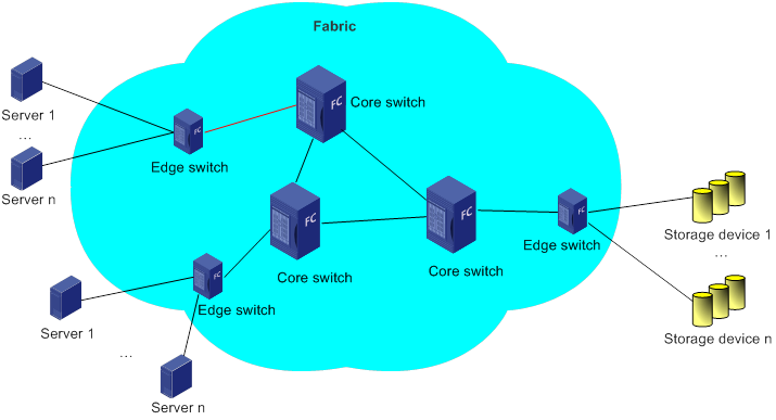
FC SAN
Figure 1 FC SAN
FC ID
In an FC SAN, servers and storage devices access each other through FC IDs, which are automatically generated and allocated by FC. An FC ID has 24 bits and is divided into three parts: domain ID, area ID, and port ID.
Figure 2 FC ID
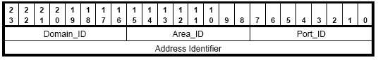
In a fabric, each FC switch (core switch and edge switch) is assigned a domain ID. The edge switch assigns FC IDs to its connected nodes based on its domain ID.
A domain ID has eight bits. In theory, there can be up to 256 domain IDs in a fabric. However, except known and reserved domain IDs, only up to 239 domain IDs are available.
NPV switch
Each FC switch is assigned a domain ID. Each FC SAN supports a maximum number of 239 domain IDs, so a fabric cannot have more than 239 switches. Therefore, FC SANs are limited in scale and scalability.
N_Port Virtualization (NPV) switches can expand an FC SAN without occupying domain IDs and therefore are widely used in FC SANs. An NPV switch is deployed at the edge of a fabric and between nodes and the core switch. It forwards data for nodes and the core switch.
Figure 3 NPV network diagram
NPV implementation
NPV
Figure 4 NPV switch port modes
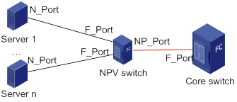
On an NPV switch, you can map multiple F ports to an NP port. In this manner, the NPV switch can relay FLOGI requests and forward data to the core switch from multiple nodes.
From the perspective of nodes, the NPV switch functions the same as the core switch. Nodes can send FLOGI requests to perform a fabric login to the NPV switch and can also request name service information.
The NPV switch appears as an NPIV-capable node to the core switch. The NPV switch can request multiple FC IDs by creating multiple virtual nodes (VNodes) on its NP port.
An NPV switch does not occupy a separate domain ID. It relays FLOGI requests to the core switch for FC ID assignment. This expands the access capacity of FC switches and reduces FC SAN operation complexity.
NPV switches can connect to FCoE-capable nodes on its downlink Ethernet interfaces and expand the storage network containing FCF switches through its uplink Ethernet interfaces.
NPIV
Figure 5 NPIV application
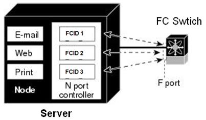
An NPV switch can support NPIV on its F port to assign multiple FC IDs for one connected physical N port.
To use NPIV on an NPV switch, make sure the NPV switch supports NPIV on its NP port. Then, the NP port can create one or more VN ports for each node connected to an F port and can relay FLOGI requests from nodes.
Mechanism
After an NPV switch becomes operational, it joins the fabric before it can relay FLOGI requests and forward data for its connected nodes.
Figure 6 NPV switch operating mechanism
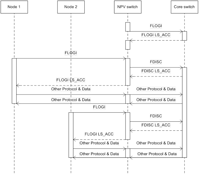
1. The NPV switch sends an FLOGI request on its NP port to the core switch to join the fabric. The NP port uses the assigned FC ID to communicate with other devices in the fabric.
2. After the NP port successfully joins the fabric, it can relay FLOGI requests from downlink interfaces through the following interaction:
a. The node sends an FLOGI request to request an FC ID and join the fabric.
b. After receiving the request on its F port, the NPV switch virtualizes a VN port to simulate the N port and obtains VN port information from the request. Then, the NP port sends an FDISC request to the core switch.
c. After receiving the request, the core switch assigns an FC ID to the node and records node login information. Then, the core switch replies with an FDISC LS_ACC packet.
d. After receiving the FDISC LS_ACC packet, the NPV switch records the assigned FC ID and forwards the LS_ACC packet with the FC ID to the requesting node.
e. After receiving the LS_ACC packet, the node takes the FC ID and successfully joins the fabric.
3. After the node successfully joins the fabric, the NPV switch directly forwards protocol or data packets from the node over the uplink NP port to the core switch. During this process, the NPV switch does not modify or process the packets.
Similarly, the NPV switch directly forwards the protocol or data packets received on its NP port to the relevant F port according to the destination FC ID.
Application scenarios
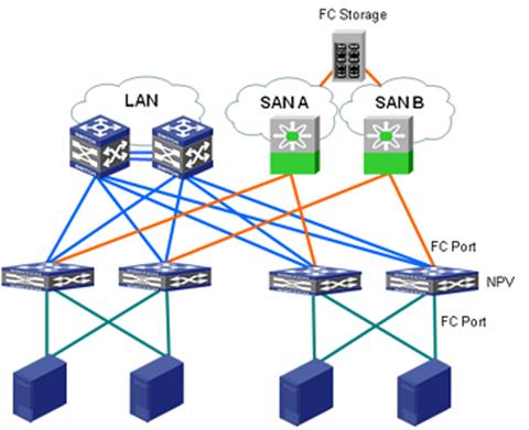
Connecting FC nodes to SANs through NPV switches
In this scenario, both uplink and downlink interfaces are FC interfaces. This networking can expand FC network capacity when necessary and reduces the number of domain IDs occupied.
Figure 7 Network diagram
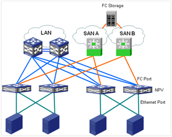
Connecting FCoE nodes to SANs through NPV switches
In this scenario, uplink interfaces are FC interfaces, and downlink interfaces are Ethernet interfaces. This networking reduces the number of domain IDs occupied. Also, this networking moves from FC to FCoE smoothly by connecting FCoE nodes to an FC network without replacing FC core switches.
Figure 8 Network diagram
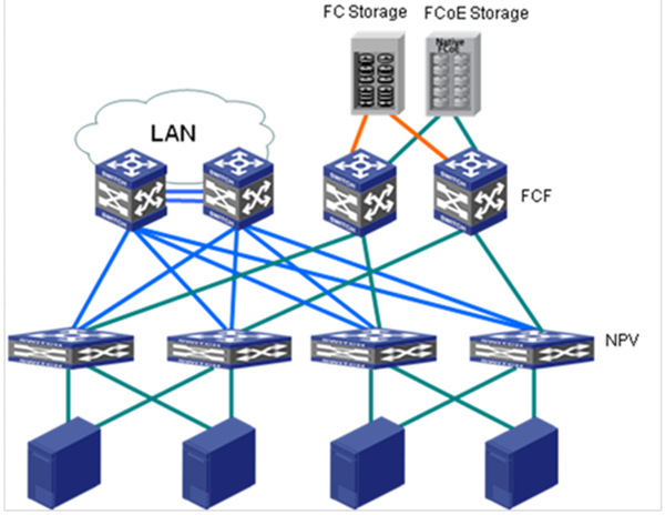
Connecting FCoE nodes to an FCoE network through NPV switches
In this scenario, both uplink and downlink interfaces are Ethernet interfaces. This networking can expand FCoE network capacity when necessary and reduces the number of domain IDs occupied.
Figure 9 Network diagram