- Table of Contents
- Related Documents
-
| Title | Size | Download |
|---|---|---|
| 04-RPR Configuration | 421.16 KB |
Centralized RPR and distributed RPR
Configuring basic RPR functions
Configuring an RPR physical port
Creating and configuring a Layer 3 RPR logical interface
Binding an RPR logical interface with RPR physical ports
Enabling RPR mate port smart connection
Changing the RPR physical port type
Configuring the RPR station name
Configuring the RPR protection mode
Configuring RPR protection reversion mode
Manually sending a protection request
Configuring the ringlet selection table
Adding a static ringlet selection entry
Configuring default ringlet selection
Configure the RPR fairness algorithm
Configuring reserved bandwidth or rate limiting
Configuring the hold off timer
Configuring the keepalive timer
Configuring the topology stability timer
Testing connectivity between RPR stations
Displaying and maintaining RPR
RPR interface binding configuration example
RPR protection/static ringlet selection configuration example
RPR overview
This section covers these topics:
· Centralized RPR and distributed RPR
Resilient Packet Ring (RPR) is a new MAC layer protocol designed for transferring mass data services over MANs. It can operate on synchronous optical network/synchronous digital hierarchy (SONET/SDH), Dense Wavelength Division Multiplexing (DWDM) and Ethernet to provide flexible and efficient networking schemes for broadband IP MANs carriers. The RPR technology delivers these benefits:
· Physical layer diversity
· High bandwidth utilization
· Multicast and broadcast support
· Automatic topology discovery and plug-and-play for stations
· Quick protection mechanism, and 50-ms self healing with topology protection
· Traffic level guarantee based on bandwidth reservation and rate limiting
· Bandwidth sharing fairness among stations on the ring
Ring structure of RPR
RPR is made up of dual unidirectional counter-rotating ringlets identified as Ringlet 0 and Ringlet 1, as shown in Figure 1.
Figure 1 Ring structure of RPR
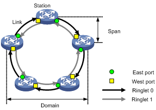
Ringlet 0, also called the “outer ring,” is for clockwise or west data traffic. Ringlet 1, also called the “inner ring,” is for counterclockwise or east data traffic.
On Ringlet 0, stations send data frames out of east ports and receive data frames from west ports. On Ringlet 1, stations send data frames out of west ports and receive data frames from east ports.
Any two adjacent stations are connected by a pair of unidirectional logical channels called “links” transmitting in opposite directions. These two links form a span. Multiple continuous spans and their stations form a domain. A span on which data frames are not allowed to pass is called an “edge.” If a ring contains at least one detected edge, it is called “open ring.” If it does not contain any detected edges, it is called “closed ring.”
Data operations on RPR
Stations on an RPR handle data frames by performing the following four types of operations:
· Insert, to place a frame on a ringlet.
· Transit, to pass a frame to the next station.
· Copy, to deliver an inbound frame from the ring to the upper layer. Copying a frame does not remove the frame from the ring.
· Strip, to remove a frame from a ringlet. The frame is not passed to the next station.
By performing these operations, stations implement unicast, broadcast, multicast, and unknown unicast transmission.
Unicast transmission
Figure 2 Unicast transmission on an RPR ring
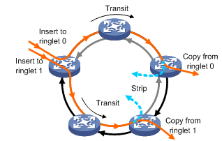
Figure 2 shows how a unicast data frame is transmitted on an RPR ringlet:
1. The source station inserts the unicast frame into the data stream on Ringlet 0 or Ringlet 1.
2. Transit stations transit the frame.
3. The frame is copied and stripped when it reaches the destination station or when its time to live (TTL) expires.
Different from traditional ring technologies where unicast frames are removed from the ring at the source station, RPR adopts destination stripping to remove unicast frames from the ring at the destination station. This increases bandwidth utilization and spatial bandwidth reuse efficiency.
Broadcast, multicast, and unknown unicast transmission
Figure 3 Broadcast, multicast, and unknown unicast transmission on an RPR ring
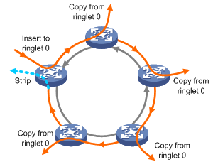
Figure 3 shows how a broadcast, multicast, or unknown unicast frame is transmitted on an RPR ringlet:
1. The source station inserts the frame into the data stream on Ringlet 0 or Ringlet 1.
2. Transit and destination stations copy and transit the frame if the TTL of the frame has not expired.
3. The frame is stripped when it returns to the source station or when its TTL expires.
Topology discovery
RPR performs automatic topology discovery to collect such information as the number of stations, ring state, and order of the stations on the ring to build a topology database. This database does not change after the ring topology becomes stable.
Topology database
Each RPR station maintains a topology database that describes the topology of the entire RPR ring. Based on this database, the station creates its ringlet selection table.
A topology database contains three categories of information:
· Ringlet topology information, such as the number of stations, ring state, and available bandwidth.
· Local station topology information, such as the MAC address, protection mode, protection state, station name, and topology checksum of the local station and the neighbor stations.
· Topology information of other stations, such as the MAC address, validity state, reachability, protection mode, station ID, station name, and reserved bandwidth.
Topology discovery process
During the topology discovery process, RPR uses the following three types of control frames to transmit topology data: topology protection (TP), attribute discovery (ATD), and topology checksum (TC).
· TP frames convey configuration and status information of stations. The stations on an RPR ring broadcast TP frames to advertise their configuration and status information, and update their own topology databases after receiving TP frames from other stations. Finally, all the stations reach an agreement on the topology of the ring.
· ATD frames convey attributes of the local station such as the MAC address and station name. These attributes will be included in the topology database.
· TC frames convey topology checksum information. They are sent between adjacent stations to check whether the topology databases on them are synchronized, identifying stability of the RPR ring topology.
All these control frames are sent at regular intervals, which are user configurable. For TP and TC frames, two types of interval, fast sending interval and slow sending interval, are used.
· When a station on the ring starts initializing or detects a topology change, it sends TP frames to propagate topology information throughout the network. When doing that, it sends the first nine TP frames at fast intervals and subsequent TP frames at slow intervals.
· After the RPR ring topology converges, the station starts to send TC frames. When doing that, it sends first five TC frames at fast intervals and then subsequent TC frames at slow intervals.
· Only one type of interval is available for sending ATD frames, regardless of topology change.
Fault response methods
RPR is available with two fault response methods: passthrough and protection.
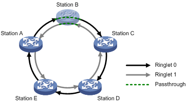
Passthrough
The passthrough approach mainly applies to handle station faults. When a station detects an internal fault, it can enter the passthrough state in which it behaves like a repeater and does not handle any services on the ring. Frames arriving at this station are forwarded directly as if it was transparent, and the station is invisible on the ring. Station B shown in Figure 4 is an example.
Figure 4 Passthrough approach
Protection
If a station is unable to forward traffic as the result of power failure or fiber cut for example, it should enter protection mode. RPR provides the following protection modes:
· Wrapping—After a span or station fails, protected traffic is directed at the point of failure to the opposing ringlet. The two ringlets (Ringlet 0 and Ringlet 1) then form a closed single ring around the point of the failure. The wrapping mode minimizes the data frame loss, because the wrapping mode allows quick switchover, However, this mode wastes bandwidth.
· Steering—The two stations at the two sides of a point of failure update their topology databases, and then send TP frames at fast intervals to the other stations on the ring. After a new topology database is stabilized, the source station directs protected frames to the ringlet that retains connectivity to their destinations. The steering mode can avoid the bandwidth waste. However, it can cause frame loss and service interruption because it requires topology reconvergence.
Figure 5 Schematic diagram before and after protection switchover
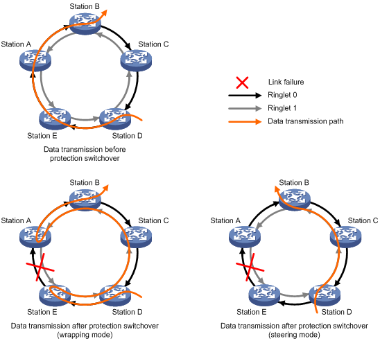
As shown in Figure 5, traffic travels from station D to station B along Ringlet 0. The transmission path is station D—station E—station A—station B. After the span between station A and station E fails, a protection switchover occurs.
· In wrapping mode, traffic that should originally travel from station E to A along Ringlet 0 is directed to Ringlet 1 to reach station A. The new transmission path is station D—station E—station D—station C—station B—station A—station B.
· In steering mode, traffic that should have traveled from station D to station B along Ringlet 0 is steered to Ringlet 1 for transmission. The new transmission path is Station D—Station C—Station B.
RPR protection switching uses the following protection hierarchy listed in the order of decreasing severity:
· Forced switch (FS)
· Signal fail (SF), related to current physical status.
· Signal degrade (SD), related to current physical status.
· Manual switch (MS)
· Wait to restore (WTR)
· Idle
Protection switching occurs only when requested by a station on the ring. The hierarchy of protection requests is the same as this protection switching hierarchy. Among protection requests, FS and MS requests are sent manually, whereas SF, SD, and WTR requests are sent automatically. If multiple protection requests appear at the same time, the higher priority protection request is processed preferentially. For example:
· The MS request sent by a station will not be processed if a higher priority protection request is present on the RPR ring.
· If an FS request is present on the current ring, the SF or SD request automatically sent as the result of a link failure will be processed only after the FS request is cleared.
Centralized RPR and distributed RPR
An RPR station is identical to an RPR logical interface bound with two RPR physical ports. The two RPR physical ports are used to transmit data to or receive data from the ring. The RPR logical interface is provided for you to make configuration.
Definitions
· If the two RPR physical ports are located on the same subcard, RPR is centralized.
· If the two RPR physical ports are located on different subcards, RPR is distributed.
Differences
The differences between distributed RPR and centralized RPR lie in that:
· In centralized RPR, when the subcard where the two RPR physical ports are located goes down, the RPR station fails.
· In distributed RPR, the down event of one subcard can cause the RPR physical port on the card to go down and edge to the RPR station. The RPR station can still work in protection mode to restore services in 50 ms.
· In distributed RPR, if two RPR physical ports are on the same RPR station, you must connect their mate ports with an optical fiber first for the RPR station to forward traffic.
RPR interface
RPR logical interface and RPR physical port overview
As described earlier, an RPR station comprises a pair of RPR physical ports, one is called the “east port” and the other is called the “west port.” Initially, the two ports were fixed on the router. The RPR station could become unusable for the impairment of either port. To address the issue, the RPR logical interface was introduced.
An RPR logical interface is identical to an RPR station. It can be bound with any two RPR physical ports. When either of the RPR physical ports fails, you can replace it with another one. Moreover, as the configuration on the RPR logical interface can be synchronized to the RPR physical ports, the configuration procedure is streamlined.
Available RPR physical port types include RPRXGE and RPRPOS. Each RPR physical port is accompanied by a mate port.
For a distributed RPR station to work, do the following:
1. Create an RPR logical interface.
2. Bind the RPR physical ports with the RPR logical interface:
¡ For an RPR station to work, you must bind its RPR logical interface with at least one RPR physical port. With only one RPR physical port, the station is working in protection mode.
¡ For the RPR station to forward traffic, before binding two RPR physical ports with the same RPR logical interface, you must connect their mate ports.
¡ You can bind any type of RPR physical ports to an RPR logical interface. However, the RPR physical ports bound to an RPR logical RPR interface must be of the same type.
RPR master/slave port
The first RPR physical port bound to the RPR logical interface is the master port, and the second RPR physical port bound to the RPR logical interface is the slave port.
All calculation concerning the operation of RPR is done on the master port, and the calculation result is synchronized to the slave port for consistency. Examples of RPR-related calculation include execution of configuration commands, protection event processing, and RPR frames sending for topology discovery.
When the master port fails or leaves the binding with the RPR logical interface, the slave port takes over as the master port.
Protocols and standards
IEEE802.17, Resilient packet ring (RPR) access method and physical layer specifications
RPR configuration task list
Complete the following tasks to configure RPR:
|
Task |
Remarks |
|
|
Optional |
||
|
Required |
||
|
Required |
||
|
Optional |
||
|
Optional |
||
|
Optional |
||
|
Optional |
||
|
Optional |
||
|
Optional |
||
|
Optional |
||
|
Optional |
||
|
Optional |
||
|
Optional |
||
|
Optional |
||
|
Optional |
||
|
Optional |
||
|
Optional |
||
|
Optional |
||
|
Optional |
||
|
Optional |
||
|
Optional |
||
Configuring basic RPR functions
Configuring an RPR physical port
|
|
NOTE: RPR physical ports include RPR XGE interfaces and RPR POS interfaces. |
To configure an RPR XGE interface:
|
Step |
Command |
Remarks |
|
1. Enter system view. |
system-view |
N/A |
|
2. Enter RPR XGE interface view. |
interface rprxge interface-number |
N/A |
|
3. Configure the description for the interface. |
description text |
Optional. By default, the description of an interface is interface-name Interface. |
|
4. Shut down the interface. |
shutdown |
Optional. Enabled by default. |
|
5. Restore the default settings of the interface. |
default |
Optional. |
To configure an RPR POS interface:
|
Step |
Command |
Remarks |
|
1. Enter system view. |
system-view |
N/A |
|
2. Enter RPR POS interface view. |
interface rprpos interface-number |
N/A |
|
3. Configure the description for the interface. |
description text |
Optional. By default, the description of an interface is interface-name Interface. |
|
4. Set the overhead bytes of the interface. |
flag { c2 | { j0 | j1 } { sdh | sonet } } flag-value |
Optional. By default, the C2 byte value of an RPR POS interface is 0x16, and the SDH J0 and J1 byte values are null. |
|
5. Set the framing format on the interface. |
frame-format { sdh | sonet } |
Optional. By default, the framing format is SDH. |
|
6. Set the SD or SF alarm threshold for the interface. |
threshold { sd | sf } value |
Optional. |
|
7. Shut down the interface. |
shutdown |
Optional. Enabled by default. |
|
8. Restore the default settings of the interface. |
default |
Optional. |
Creating and configuring a Layer 3 RPR logical interface
To create and configure a Layer 3 RPR logical interface:
|
Step |
Command |
Remarks |
|
1. Enter system view. |
system-view |
N/A |
|
2. Create a Layer 3 RPR logical interface and enter Layer 3 RPR logical interface view. |
interface rpr interface-number |
N/A |
|
3. Configure the description for the interface. |
description text |
Optional. By default, the description of an RPR interface is interface-name Interface. |
|
4. Configure the MTU of the interface. |
mtu size |
Optional. 1500 bytes by default. |
|
5. Shut down the interface. |
shutdown |
Optional. Enabled by default. |
|
6. Restore the default settings of the interface. |
default |
Optional. |
Binding an RPR logical interface with RPR physical ports
To create an RPR station, you must create an RPR logical interface first and then bind RPR physical ports with the interface. You may bind RPR physical ports with an RPR logical interface in RPR logical interface view or RPR physical port view. In either case, you must create the RPR logical interface first.
Binding RPR physical ports with an RPR logical interface in RPR logical interface view
To bind RPR physical ports with an RPR logical interface in RPR logical interface view:
|
Step |
Command |
Remarks |
|
1. Enter system view. |
system-view |
N/A |
|
2. Enter RPR logical interface view. |
interface rpr interface-number |
N/A |
|
3. Bind a physical port with the RPR logical interface. |
rpr bind { { rprpos | rprxge } interface-number } { ringlet0 | ringlet1 } |
By default, no RPR physical ports are bound with an RPR logical interface. |
Binding RPR physical ports with an RPR logical interface in RPR physical port view
To bind RPR physical ports with an RPR logical interface in RPR physical port view:
|
Step |
Command |
Remarks |
|
1. Enter system view. |
system-view |
N/A |
|
2. Enter RPR physical port view. |
interface { rprpos | rprxge } interface-number |
N/A |
|
3. Bind the RPR logical interface with the physical port. |
rpr bind { rpr interface-number } { ringlet0 | ringlet1 } |
By default, no RPR physical ports are bound with an RPR logical interface. |
Enabling RPR mate port smart connection
For an RPR station to forward traffic, before binding its two RPR physical ports with the same logical RPR interface, you must connect their mate ports.
When the two RPR physical ports are on the same subcard (centralized RPR), you can enable the RPR mate port smart connection function. With the function enabled, RPR automatically connects the two mate ports without you having to connect them manually.
To enable RPR mate port smart connection:
|
Step |
Command |
Remarks |
|
1. Enter system view. |
system-view |
N/A |
|
2. Enter RPR logical interface view. |
interface rpr interface-number |
N/A |
|
3. Enable RPR mate port smart connection. |
rpr mate smart-connect |
Disabled by default. |
Changing the RPR physical port type
To change the RPR physical port type on an RPR logical interface:
|
Step |
Command |
|
1. Enter system view. |
system-view |
|
2. Enter RPR physical port view. |
interface { rprpos | rprxge } interface-number |
|
3. Change the RPR physical port type. |
rpr port-type { 10gpos | 10ge } |
|
|
NOTE: · After you change the RPR physical port type, the subcard will reboot to have the change take effect, and the previous configuration of the RPR physical port will be lost. · The rpr port-type command takes effect only on 10GPOS and 10GE RPR physical ports. It cannot take effect on 2.5GPOS RPR ports. |
Configuring the RPR station name
To assign a name to the RPR station:
|
Step |
Command |
Remarks |
|
1. Enter system view. |
system-view |
N/A |
|
2. Enter RPR logical interface view. |
interface rpr interface-number |
N/A |
|
3. Configure a station name. |
rpr station-name station-name |
No station name is configured by default. |
Configuring RPR protection
Configuring the RPR protection mode
To configure the protection mode on the RPR station:
|
Step |
Command |
Remarks |
|
1. Enter system view. |
system-view |
N/A |
|
2. Enter RPR logical interface view. |
interface rpr interface-number |
N/A |
|
3. Configure the protection mode. |
rpr protect-mode { steer | wrap } |
By default, the steering mode applies. |
|
|
CAUTION: All the stations on an RPR ring must adopt the same protection mode for the ring to operate properly. |
Configuring RPR protection reversion mode
Two protection reversion modes are available: revertive and non-revertive.
· In revertive mode, a station resumes the idle protection state once the WTR timer expires.
· In non-revertive mode, the station remains in automatic protection state upon expiration of the WTR timer and does not resume the idle state until a higher protection request is present on the ring.
To configure the RPR protection reversion mode on the RPR station:
|
Step |
Command |
Remarks |
|
1. Enter system view. |
system-view |
N/A |
|
2. Enter RPR logical interface view. |
interface rpr interface-number |
N/A |
|
3. Configure the protection reversion mode. |
rpr reversion-mode { revertive | non-revertive } |
Optional. Revertive mode applies by default. |
Manually sending a protection request
You can send FS or MS protection requests to trigger protection switchover or send idle protection requests to clear manually sent protection requests on the RPR station.
To send a protection request:
|
Step |
Command |
|
1. Enter system view. |
system-view |
|
2. Enter RPR logical interface view. |
interface rpr interface-number |
|
3. Send an RPR protection request on a ringlet. |
rpr admin-request { fs | ms | idle } { ringlet0 | ringlet1 } |
Configuring the ringlet selection table
Each RPR station maintains a ringlet selection table for making ringlet selection decisions for frame transmission. A ringlet selection table entry contains such information as the MAC address of a station, the ringlet through which frames are transmitted.
The following are supported RPR ringlet selection tables:
· Static ringlet selection table is administratively configured to specify the ringlet for delivering a frame to a destination station.
· Dynamic ringlet selection table is built dynamically based on the topology database, also known as “shortest path ringlet selection table.”
· Default ringlet selection table specifies the default ringlet for delivering frames.
· Overall ringlet selection table is created from the above three tables. In the case of closed ringlets, static ringlet selection table has the highest priority. If a static ringlet selection entry is available for reaching a destination station, it is added into the overall ringlet selection table. If no static entry is available, the system looks at the dynamic ringlet selection table. If two shortest paths are available, default ringlet selection applies to pick up one from them. The selected entry is then added into the overall ringlet selection table. When sending frames, the station consults this table to identify the path to the destination MAC address. In the case of open ringlets, the overall ringlet selection table can be created from only the dynamic ringlet selection table.
Adding a static ringlet selection entry
To add an entry to the static ringlet selection table:
|
Step |
Command |
Remarks |
|
1. Enter system view. |
system-view |
N/A |
|
2. Enter RPR logical interface view. |
interface rpr interface-number |
N/A |
|
3. Add a static ringlet selection entry. |
rpr static-rs mac-address { ringlet0 | ringlet1 } |
No static ringlet selection entry is created by default. |
|
|
NOTE: Static ringlet selection entries take effect only when the RPR ring is closed. |
Configuring default ringlet selection
To configure the default ringlet selection:
|
Step |
Command |
Remarks |
|
1. Enter system view. |
system-view |
N/A |
|
2. Enter RPR logical interface view. |
interface rpr interface-number |
N/A |
|
3. Configure default ringlet selection. |
rpr default-rs { ringlet0 | ringlet1 } |
Optional. By default, the default ringlet is Ringlet 0. |
|
|
NOTE: When a span is faulty and unable to forward data on the default ringlet you configured, another ringlet works as the default ringlet. |
Configure the RPR fairness algorithm
By configuring the RPR fairness algorithm, you can better guarantee the transmission quality over RPR rings.
Configuring reserved bandwidth or rate limiting
RPR traffic fall into three classes: class A, class B, and class C, with decreasing priorities.
· Class A is further divided into two subclasses: A0 and A1. RPR can reserve bandwidth for subclass A0. When congestion occurs, the unused reserved bandwidth cannot be used by lower priority traffic. Subclass A1 is rate limited. When congestion occurs, subclass A1 allows lower priority traffic to use its unused bandwidth, and bandwidth allocation is regulated by the fairness algorithm.
· Class B can also be divided into two subclasses: B-CIR and B-EIR. For class B traffic, the portion within the predefined rate limit belongs to class B-CIR and the portion exceeding the limit belongs to class B-EIR. Similar to traffic of class C, traffic of class B-EIR is regulated by the fairness algorithm.
· Traffic of class C is regulated by the fairness algorithm and takes the lowest priority.
To configure reserved bandwidth or rate limit for a certain traffic class:
|
Step |
Command |
Remarks |
|
1. Enter system view. |
system-view |
N/A |
|
2. Enter RPR logical interface view. |
interface rpr interface-number |
N/A |
|
3. Configure reserved bandwidth or rate limit for a class on a certain ringlet. |
rpr rate-limiter { high | low | medium | reserved } { ringlet0 | ringlet1 } value |
By default, no bandwidth is reserved for subclass A0; the rate limit is 2‰ for subclass A1, 0‰ for class B-CIR, and 1000‰ for B-EIR and class C. |
|
|
NOTE: The total bandwidth reserved for subclass A0 by the stations on a ringlet must be less than the ringlet bandwidth. |
Configuring station weight
On an RPR ring, bandwidth resources are shared among stations. When traffic size is small, RPR can handle bandwidth requests of all stations on the ring well. When traffic size gets heavy, congestion may occur. To prevent some stations from taking advantage of their spatially or chronologically favorable position on the ring to occupy excessive bandwidth, RPR adopts a fairness algorithm to ensure bandwidth allocation fairness.
The fairness algorithm of RPR mainly regulates class B-EIR and class C traffic on the RPR ring. You can assign a weight to a station to adjust the ratio of its available service bandwidth to the total non-reserved bandwidth on a ringlet. The fairness weight of a station is configured as an exponent of 2.
To configure the fairness weight of an RPR station on a ringlet:
|
Step |
Command |
Remarks |
|
1. Enter system view. |
system-view |
N/A |
|
2. Enter RPR logical interface view. |
interface rpr interface-number |
N/A |
|
3. Configure the weight of the station. |
rpr weight { ringlet0 | ringlet1 } value |
By default, the weight is 20=1. |
Configuring RPR timers
These are the RPR timer configuration tasks:
· Configuring the hold off timer
· Configuring the keepalive timer
· Configuring the topology stability timer
Configuring the ATD timer
The ATD timer defines the interval at which attribute discovery frames are sent.
To configure the ATD timer:
|
Step |
Command |
Remarks |
|
1. Enter system view. |
system-view |
N/A |
|
2. Enter RPR logical interface view. |
interface rpr interface-number |
N/A |
|
3. Set the ATD timer. |
rpr timer atd atd-value |
1 second by default. |
Configuring the hold off timer
The hold off timer defines the delay for the physical layer to report a protection request after detecting a link failure.
To configure the hold off timer:
|
Step |
Command |
Remarks |
|
1. Enter system view. |
system-view |
N/A |
|
2. Enter RPR logical interface view. |
interface rpr interface-number |
N/A |
|
3. Set the hold off timer. |
rpr timer holdoff holdoff-value |
0 milliseconds by default. |
Configuring the keepalive timer
A station sends single choke fairness frames (SCFFs) periodically to notify the neighbor stations of its normal operation state. When a station fails to receive an SCFF, a keepalive timer starts. If no SCFF frame is received after the timer expires, the station sends an SF protection request.
To configure the keepalive timer:
|
Step |
Command |
Remarks |
|
1. Enter system view. |
system-view |
N/A |
|
2. Enter RPR logical interface view. |
interface rpr interface-number |
N/A |
|
3. Set the keepalive timer. |
rpr timer keepalive keepalive-value |
3 milliseconds by default. |
Configuring the topology stability timer
When a station detects a topology change on the ring, it starts the topology stability timer and begins to collect topology information to update its topology database. After the timer expires, the station checks the validity of received topology information. If the information is valid, the station enters topology valid state; if not, the station re-starts the timer.
To configure the topology stability timer:
|
Step |
Command |
Remarks |
|
1. Enter system view. |
system-view |
N/A |
|
2. Enter RPR logical interface view. |
interface rpr interface-number |
N/A |
|
3. Set the topology stability timer. |
rpr timer stability stability-value |
40 milliseconds by default. |
Configuring the TC timers
The TC fast/slow timer defines the fast/slow interval at which TC frames are sent. When the ring topology checksum changes, five TC frames are sent at the fast interval; when the ring topology is stable, TC frames are sent at the slow interval.
To configure the TC timers:
|
Step |
Command |
Remarks |
|
1. Enter system view. |
system-view |
N/A |
|
2. Enter RPR logical interface view. |
interface rpr interface-number |
N/A |
|
3. Set the TC fast timer. |
rpr timer tc-fast tc-fast-value |
10 milliseconds by default. |
|
4. Set the TC slow timer. |
rpr timer tc-slow tc-slow-value |
100 milliseconds by default. |
Configuring the TP timers
The TP fast/slow timer defines the fast/slow interval at which TP frames are sent. When a station starts initializing or detects a topology change, nine TP frames are sent at the fast interval. When the ring topology is stable, the station begins to send TP frames at the slow interval.
To configure the TP timers:
|
Step |
Command |
Remarks |
|
1. Enter system view. |
system-view |
N/A |
|
2. Enter RPR logical interface view. |
interface rpr interface-number |
N/A |
|
3. Set the TP fast timer. |
rpr timer tp-fast tp-fast-value |
10 milliseconds by default. |
|
4. Set the TP slow timer. |
rpr timer tp-slow tp-slow-value |
100 milliseconds by default. |
Configuring the WTR timer
When a protection switching event occurs on a station due to link failure, the station enters automatic protection state; after the link recovers, the station enters the idle protection state. The WTR timer defines the delay that a station transits to the idle protection state after entering the automatic protection state.
To configure the WTR timer:
|
Step |
Command |
Remarks |
|
1. Enter system view. |
system-view |
N/A |
|
2. Enter RPR logical interface view. |
interface rpr interface-number |
N/A |
|
3. Set the WTR timer. |
rpr timer wtr wtr-value |
10 milliseconds by default. |
Testing connectivity between RPR stations
You may use Echo Request/Echo Response messages to test the connectivity between two stations and locate failure points if any. The connectivity between the current station and the destination station is considered as normal if the connection between the two stations is normal on both the sending ringlet and the receiving ringlet. The destination station should be able to receive the Echo Request messages that the current station sends along the specific ringlet, and the current station should be able to receive the Echo Response messages that the destination station sends along the specific ringlet. Otherwise, the connectivity between the current station and the destination station is considered as having failed.
To test the connectivity to a specific RPR station:
|
Step |
Command |
Remarks |
|
1. Enter system view. |
system-view |
N/A |
|
2. Enter RPR logical interface view. |
interface rpr interface-number |
N/A |
|
3. Test the connectivity between the current station and a specific station. |
rpr echo mac mac-address [ -c c-value | -r { ringlet0 | ringlet1 | reverse } | -s { ringlet0 | ringlet1 } | -t t-value ] * |
By default, five Echo Request packets are sent; it is the default ringlet that sends Echo Response packets and Echo Request packets; the timeout time is 10 milliseconds. |
|
|
NOTE: If neither the sending ringlet nor the receiving ringlet is specified, the default ringlet in use will be used for transmitting Echo Request packets and Echo Response. |
Displaying and maintaining RPR
|
Task |
Command |
Remarks |
|
Display information about an RPR physical port. |
display interface [ rprpos | rprxge ] [ brief [ down ] ] [ | { begin | exclude | include } regular-expression ] display interface { rprpos | rprxge } interface-number [ brief ] [ | { begin | exclude | include } regular-expression ] |
Available in any view |
|
Display information about an RPR logical interface. |
display interface [ rpr ] [ brief [ down ] ] [ | { begin | exclude | include } regular-expression ] display interface rpr interface-number [ brief ] [ | { begin | exclude | include } regular-expression ] |
Available in any view |
|
Display RPR logical interface-to-RPR physical port bindings. |
display rpr bind-info [ { rprpos | rprxge | rpr } interface-number ] [ | { begin | exclude | include } regular-expression ] |
Available in any view |
|
Display RPR defect information. |
display rpr defect [ interface-type interface-number ] [ | { begin | exclude | include } regular-expression ] |
Available in any view |
|
Display RPR fairness settings. |
display rpr fairness [ rpr interface-number ] [ | { begin | exclude | include } regular-expression ] |
Available in any view |
|
Display RPR protection information. |
display rpr protection [ rpr interface-number ] [ | { begin | exclude | include } regular-expression ] |
Available in any view |
|
Display RPR ringlet selection table information. |
display rpr rs-table { default | dynamic | overall | static } [ rpr interface-number ] [ | { begin | exclude | include } regular-expression ] |
Available in any view |
|
Display the settings of all configurable RPR timers. |
display rpr timers [ rpr interface-number ] [ | { begin | exclude | include } regular-expression ] |
Available in any view |
|
Display RPR topology information. |
display rpr topology { all | local | ring | stations } [ summary ] [ rpr interface-number ] [ | { begin | exclude | include } regular-expression ] |
Available in any view |
|
Clear the statistics about protection events on the RPR station. |
reset rpr protection statistics [ rpr interface-number ] |
Available in user view |
|
Clear the statistics of the specified RPR physical ports. |
reset counters interface [ { rprpos | rprxge } [ interface-number ] ] |
Available in any view |
|
Clear the statistics of the specified RPR logical interfaces. |
reset counters interface [ rpr [ interface-number ] ] |
Available in any view |
RPR configuration examples
RPR interface binding configuration example
Network requirements
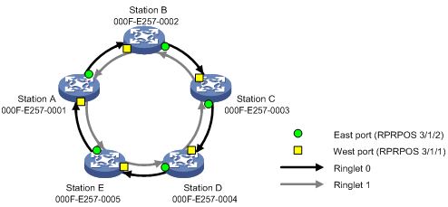
As shown in Figure 6:
· Stations A through E form an RPR ring.
· Bind the RPR physical ports to the logical interface on each station.
Configuration procedure
1. Create an RPR logical interface and bind two RPR physical ports to the logical interface:
# On Station A, create Layer 3 RPR logical interface RPR1, and bind RPR physical ports RPRPOS 3/1/1 (the west port) and RPRPOS 3/1/2 (the east port) to RPR 1.
<StationA> system-view
[StationA] interface rpr 1
[StationA-RPR1] rpr bind RPRPOS 3/1/1 ringlet0
[StationA-RPR1] rpr bind RPRPOS 3/1/2 ringlet1
[StationA-RPR1] quit
The configuration steps on Station B, C, D, and E are similar to those on Station A and not shown.
2. Verify the configuration:
# Display RPR interface binding information on Station A.
[StationA-RPR1] display rpr bind-info
Bind information on interface: RPR1
Smart-connection: Disabled
PHY-Interface Ringlet-ID Role Mate-Port
---------------------------------------------------
RPRPOS3/1/1 Ringlet0 Master Up
RPRPOS3/1/2 Ringlet1 Slave Up
# Display the RPR topology summary on Station A.
[StationA] display rpr topology all summary
Topology information items
Psw:protection state, west Pse:protection state, east
Esw:edge state, west Ese:edge state, east
Wc:wrap protection configured Jp:jumbo frame preferred
Ring-level topology information on interface: RPR1
Ringlet0 Ringlet1 Ring Jumbo-Prefer Topology-Type
-------------------------------------------------
4 4 5 Regular Closed ring
Local station topology information on interface: RPR1
MAC-Address Psw Pse Esw Ese Wc Jp IP-Address Station-Name
---------------------------------------------------------------------
000f-e257-0001 Idle Idle 0 0 0 0 0.0.0.0
Station topology information on interface: RPR1
Station entry on ringlet0
MAC-Address Psw Pse Esw Ese Wc Jp IP-Address Station-Name
---------------------------------------------------------------------
000f-e257-0005 Idle Idle 0 0 0 0 0.0.0.0
000f-e257-0004 Idle Idle 0 0 0 0 0.0.0.0
000f-e257-0003 Idle Idle 0 0 0 0 0.0.0.0
000f-e257-0002 Idle Idle 0 0 0 0 0.0.0.0
Station entry on ringlet1
MAC-Address Psw Pse Esw Ese Wc Jp IP-Address Station-Name
---------------------------------------------------------------------
000f-e257-0002 Idle Idle 0 0 0 0 0.0.0.0
000f-e257-0003 Idle Idle 0 0 0 0 0.0.0.0
000f-e257-0004 Idle Idle 0 0 0 0 0.0.0.0
000f-e257-0005 Idle Idle 0 0 0 0 0.0.0.0
The topology information shows that the RPR ring is closed.
RPR protection/static ringlet selection configuration example
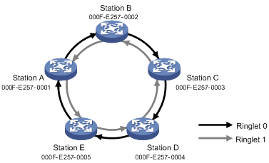
Network requirements
As shown in Figure 7, Stations A through E form an RPR ring and work in steering protection mode by default.
Do the following:
· Change the protection mode of the ring to wrapping.
· Configure a static ringlet selection entry to allow frames from Station A to Station B to travel Ringlet 1 when no edge occurs on the RPR ring (that is, the ring remains closed).
Configuration procedure
1. Configure the protection mode:
# Create Layer 3 RPR logical interface RPR 1 on Station A, and configure the protection mode as wrapping on the interface.
<StationA> system-view
[StationA] interface rpr 1
[StationA-RPR1] rpr protect-mode wrap
The configuration steps on Station B through Station E are similar to those on Station A and not shown.
2. Configure static ringlet selection:
# On Layer 3 RPR logical interface RPR 1 of Station A, configure transmitting frames destined for Station B through Ringlet 1.
[StationA-RPR1] rpr static-rs 000f-e257-0002 ringlet1
[StationA-RPR1] quit
3. Verify the configuration:
# Display ring topology information on Station A.
[StationA] display rpr topology ring
Ring-level topology information on interface: RPR1
Stations on ringlet0: 4
Stations on ringlet1: 4
Total stations on ring: 5
Jumbo preference: regular
Ring topology type: closed ring
# Display the static ring selection table information on Station A.
[StationA] display rpr rs-table static
Static ringlet selection table on interface: RPR1
MAC-Address Ringlet-ID Status
-----------------------------------
000f-e257-0002 Ringlet1 Valid
--- Total entrie(s): 1 ---
# Display the information about the overall ring selection table on Station A.
[StationA] display rpr rs-table overall
Overall ringlet selection table on interface: RPR1
MAC-Address Ringlet-ID TTL Type IP-Address Station-Name
--------------------------------------------------------------------------
000f-e257-0002 Ringlet1 4 static 0.0.0.0
000f-e257-0003 Ringlet0 2 dynamic 0.0.0.0
000f-e257-0004 Ringlet1 2 dynamic 0.0.0.0
000f-e257-0005 Ringlet1 1 dynamic 0.0.0.0
--- Total entrie(s): 4 ---
