- Table of Contents
-
- 10-Security Configuration Guide
- 00-Preface
- 01-AAA Configuration
- 02-802.1X Configuration
- 03-MAC Authentication Configuration
- 04-Portal Configuration
- 05-Password Control Configuration
- 06-Public Key Configuration
- 07-IPsec Configuration
- 08-SSH Configuration
- 09-Packet-Filter Firewall Configuration
- 10-ALG Configuration
- 11-Session Management Configuration
- 12-TCP and ICMP Attack Protection Configuration
- 13-IP Source Guard Configuration
- 14-ARP Attack Protection Configuration
- 15-URPF Configuration
- 16-COPS Configuration
- 17-FIPS Configuration
- 18-PKI Configuration
- Related Documents
-
| Title | Size | Download |
|---|---|---|
| 14-ARP Attack Protection Configuration | 126.73 KB |
Contents
Configuring ARP attack protection·
ARP attack protection overview
ARP attack protection configuration task list
Configuring ARP defense against IP packet attacks
Configuring ARP source suppression
Enabling ARP black hole routing
Displaying and maintaining ARP defense against IP packet attacks
Configuring source MAC address based ARP attack detection
Displaying and maintaining source MAC address based ARP attack detection
Configuring ARP active acknowledgement
Authorized ARP configuration example (on a DHCP server)
Authorized ARP configuration example (on a DHCP relay agent)
ARP attack protection overview
Although ARP is easy to implement, it provides no security mechanism and thus is prone to network attacks. An attacker can send
· ARP packets by acting as a trusted user or gateway. As a result, the receiving router obtains incorrect ARP entries, and thus a communication failure occurs.
· A large number of IP packets with unreachable destinations. As a result, the receiving router continuously resolves destination IP addresses and thus its CPU is overloaded.
· A large number of ARP packets to bring a great impact to the CPU.
For more information about ARP attack features and types, see ARP Attack Protection Technology White Paper.
ARP attacks and viruses are threatening LAN security. The router can provide multiple features to detect and prevent such attacks. This chapter mainly introduces these features.
ARP attack protection configuration task list
Complete the following tasks to configure ARP attack protection:
|
Task |
Remarks |
||
|
Flood prevention |
Optional Configure this function on gateways (recommended). |
||
|
Optional Configure this function on gateways (recommended). |
|||
|
Optional Configure this function on gateways (recommended). |
|||
|
User and gateway spoofing prevention |
Optional Configure this function on gateways (recommended). |
||
Configuring ARP defense against IP packet attacks
Introduction
If a router receives a large number of IP packets from a host to unreachable destinations,
· The router sends a large number of ARP requests to the destination subnets, which increases the load of the destination subnets.
· The router keeps trying to resolve destination IP addresses, which increases the load of the CPU.
To protect the router from IP packet attacks, you can enable the ARP source suppression function or ARP black hole routing function.
If the packets have the same source address, you can enable the ARP source suppression function. With the function enabled, whenever the number of ARP requests triggered by the packets with unresolvable destination IP addresses from a host within five seconds exceeds a specified threshold, the router suppresses the sending host from triggering any ARP requests within the following five seconds.
If the packets have various source addresses, you can enable the ARP black hole routing function. After receiving an IP packet whose destination IP address cannot be resolved by ARP, the router with this function enabled immediately creates a black hole route and simply drops all packets matching the route during the aging time (defaults to 25 seconds) of the black hole route.
Configuring ARP source suppression
To configure ARP source suppression:
|
Step |
Command |
Remarks |
|
1. Enter system view. |
system-view |
N/A |
|
2. Enable ARP source suppression. |
arp source-suppression enable |
Disabled by default |
|
3. Set the maximum number of packets with the same source IP address but unresolvable destination IP addresses that the router can receive in five consecutive seconds. |
arp source-suppression limit limit-value |
Optional 10 by default |
Enabling ARP black hole routing
To configure ARP black hole routing:
|
Step |
Command |
Remarks |
|
1. Enter system view. |
system-view |
N/A |
|
2. Enable ARP black hole routing. |
arp resolving-route enable |
Optional Enabled by default |
Displaying and maintaining ARP defense against IP packet attacks
|
Task |
Command |
Remarks |
|
Display the ARP source suppression configuration information. |
display arp source-suppression [ | { begin | exclude | include } regular-expression ] |
Available in any view |
Configuring source MAC address based ARP attack detection
Introduction
This feature allows the router to check the source MAC address of ARP packets. If the number of ARP packets sent from a MAC address within five seconds exceeds the specified threshold, the router considers this an attack and adds the MAC address to the attack detection table. Before the attack detection entry is aged out, the router generates a log message upon receiving an ARP packet sourced from that MAC address and filters out subsequent ARP packets from that MAC address (in filter mode), or only generates a log message upon receiving an ARP packet sourced from that MAC address (in monitor mode).
A gateway or critical server may send a large number of ARP packets. To prevent these ARP packets from being discarded, you can specify the MAC address of the gateway or server as a protected MAC address. A protected MAC address is excluded from ARP attack detection even if it is an attacker.
Only the ARP packets delivered to the CPU are detected.
Configuration procedure
To configure source MAC address based ARP attack detection:
|
Step |
Command |
Remarks |
|
1. Enter system view. |
system-view |
N/A |
|
2. Enable source MAC address based ARP attack detection and specify the detection mode. |
arp anti-attack source-mac { filter | monitor } |
Disabled by default. |
|
3. Configure the threshold. |
arp anti-attack source-mac threshold threshold-value |
Optional. 50 by default. |
|
4. Configure the aging timer for source MAC address based ARP attack detection entries. |
arp anti-attack source-mac aging-time time |
Optional. 300 seconds by default. |
|
5. Configure protected MAC addresses. |
arp anti-attack source-mac exclude-mac mac-address&<1-n> |
Optional. By default, no protected MAC address is configured. The maximum value of n is 10. |
|
|
NOTE: After an ARP attack detection entry expires, the MAC address of the entry becomes ordinary. |
Displaying and maintaining source MAC address based ARP attack detection
|
Task |
Command |
Remarks |
|
Display attacking entries detected. |
display arp anti-attack source-mac { slot slot-number | interface interface-type interface-number } [ | { begin | exclude | include } regular-expression ] |
Available in any view |
Configuring ARP active acknowledgement
Introduction
Typically, the ARP active acknowledgement feature is configured on gateway devices to identify invalid ARP packets.
ARP active acknowledgement works before the gateway creates or modifies an ARP entry to avoid generating any incorrect ARP entry. For more information about its working mechanism, see ARP Attack Protection Technology White Paper.
Configuration procedure
To configure ARP active acknowledgement:
|
Step |
Command |
Remarks |
|
1. Enter system view. |
system-view |
N/A |
|
2. Enable the ARP active acknowledgement function. |
arp anti-attack active-ack enable |
Disabled by default |
Configuring authorized ARP
|
|
NOTE: For more information about the DHCP server and DHCP relay agent, see Layer 3—IP Services Configuration Guide. |
Introduction
Authorized ARP entries are generated based on the DHCP clients’ address leases on the DHCP server or dynamic bindings on the DHCP relay agent.
After enabled with authorized ARP, an interface is disabled from learning dynamic ARP entries to prevent attacks from unauthorized clients that send packets using other clients’ IP or MAC addresses, and to allow only authorized clients to access network resources. Thus network security is enhanced.
|
|
NOTE: Static ARP entries can overwrite authorized ARP entries, and authorized ARP entries can overwrite dynamic ARP entries. But authorized ARP entries cannot overwrite static ARP entries, and dynamic ARP entries cannot overwrite authorized ARP entries. |
Configuration procedure
To enable authorized ARP:
|
Step |
Command |
Remarks |
|
1. Enter system view. |
system-view |
N/A |
|
2. Enter interface view. |
interface interface-type interface-number |
N/A |
|
3. Configure the DHCP server (or DHCP relay agent) to support authorized ARP. |
dhcp update arp |
Not configured by default |
|
4. Enable authorized ARP on the interface. |
arp authorized enable |
Disabled by default |
Authorized ARP configuration example (on a DHCP server)
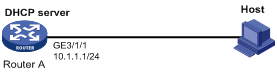
Network requirements
As shown in Figure 1, Router A acts as a DHCP server with an IP address pool of 10.1.1.0/24. Enable authorized ARP on GigabitEthernet 3/1/1 of Router A. The host obtains an IP address of 10.1.1.2/24 from the DHCP server.
Configuration procedure
1. Configure Router A:
# Configure the IP address of GigabitEthernet 3/1/1.
<RouterA> system-view
[RouterA] interface GigabitEthernet 3/1/1
[RouterA-GigabitEthernet3/1/1] ip address 10.1.1.1 24
[RouterA-GigabitEthernet3/1/1] quit
# Configure DHCP.
[RouterA] dhcp enable
[RouterA] dhcp server ip-pool 1
[RouterA-dhcp-pool-1] network 10.1.1.0 mask 255.255.255.0
[RouterA-dhcp-pool-1] quit
# Enter Ethernet interface view.
[RouterA] interface GigabitEthernet 3/1/1
# Configure the DHCP server to support authorized ARP.
[RouterA-GigabitEthernet3/1/1] dhcp update arp
# Enable authorized ARP.
[RouterA-GigabitEthernet3/1/1] arp authorized enable
2. After the host obtains an IP address from Router A, display the authorized ARP entry information on Router A.
[RouterA] display arp all
Type: S-Static D-Dynamic A-Authorized
IP Address MAC Address VLAN ID Interface Aging Type
10.1.1.2 0012-3f86-e94c N/A GE3/1/1 N/A A
The output shows that an IP address of 10.1.1.2 has been assigned to the host.
After that, the host must use the IP address and MAC address that are consistent with those in the authorized ARP entry to communicate with Router A; otherwise, the communication fails. Thus the client validity is guaranteed.
Authorized ARP configuration example (on a DHCP relay agent)
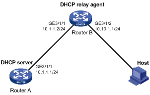
Network requirements
As shown in Figure 2, Router A acts as a DHCP server with an IP address pool of 10.10.1.0/24. Router B is a DHCP relay agent, which conveys the IP address from the DHCP server to the host.. Enable authorized ARP on GigabitEthernet 3/1/2 of Router B.
Configuration procedure
1. Configure Router A:
# Configure the IP address of GigabitEthernet 3/1/1.
<RouterA> system-view
[RouterA] interface GigabitEthernet 3/1/1
[RouterA-GigabitEthernet3/1/1] ip address 10.1.1.1 24
[RouterA-GigabitEthernet3/1/1] quit
# Configure DHCP.
[RouterA] dhcp enable
[RouterA] dhcp server ip-pool 1
[RouterA-dhcp-pool-1] network 10.10.1.0 mask 255.255.255.0
[RouterA-dhcp-pool-1] gateway-list 10.10.1.1
[RouterA-dhcp-pool-1] quit
[RouterA] ip route-static 10.10.1.0 24 10.1.1.2
2. Configure Router B:
# Enable DHCP.
<RouterB> system-view
[RouterB] dhcp enable
# Configure the IP addresses of GigabitEthernet 3/1/1 and GigabitEthernet 3/1/2.
[RouterB] interface GigabitEthernet 3/1/1
[RouterB-GigabitEthernet3/1/1] ip address 10.1.1.2 24
[RouterB-GigabitEthernet3/1/1] quit
[RouterB] interface GigabitEthernet 3/1/2
[RouterB-GigabitEthernet3/1/2] ip address 10.10.1.1 24
# Enable DHCP relay agent on GigabitEthernet 3/1/2.
[RouterB-GigabitEthernet3/1/2] dhcp select relay
[RouterB-GigabitEthernet3/1/2] quit
# Add the DHCP server 10.1.1.1 to DHCP server group 1.
[RouterB] dhcp relay server-group 1 ip 10.1.1.1
# Correlate GigabitEthernet 3/1/2 to DHCP server group 1.
[RouterB] interface GigabitEthernet 3/1/2
[RouterB-GigabitEthernet3/1/2] dhcp relay server-select 1
# Configure the DHCP server to support authorized ARP.
[RouterB-GigabitEthernet3/1/2] dhcp update arp
# Enable authorized ARP.
[RouterB-GigabitEthernet3/1/2] arp authorized enable
# Configure the aging time for authorized ARP entries.
[RouterB-GigabitEthernet3/1/2] arp authorized time-out 120
[RouterB-GigabitEthernet3/1/2] quit
3. After the host obtains the IP address from Router A, display the authorized ARP information on Router B.
[RouterB] display arp all
Type: S-Static D-Dynamic A-Authorized
IP Address MAC Address VLAN ID Interface Aging Type
10.10.1.2 0012-3f86-e94c N/A GE3/1/2 N/A A
The output shows that Router A assigned an IP address of 10.10.1.2 to the host.
After that, the host must use the IP address and MAC address that are consistent with those in the authorized ARP entry to communicate with Router B; otherwise, the communication fails. Thus the client validity is guaranteed.
