- Table of Contents
-
- 10-Security Configuration Guide
- 00-Preface
- 01-AAA Configuration
- 02-802.1X Configuration
- 03-MAC Authentication Configuration
- 04-Portal Configuration
- 05-Password Control Configuration
- 06-Public Key Configuration
- 07-IPsec Configuration
- 08-SSH Configuration
- 09-Packet-Filter Firewall Configuration
- 10-ALG Configuration
- 11-Session Management Configuration
- 12-TCP and ICMP Attack Protection Configuration
- 13-IP Source Guard Configuration
- 14-ARP Attack Protection Configuration
- 15-URPF Configuration
- 16-COPS Configuration
- 17-FIPS Configuration
- 18-PKI Configuration
- Related Documents
-
| Title | Size | Download |
|---|---|---|
| 01-AAA Configuration | 1.48 MB |
Contents
AAA configuration considerations and task list
Configuring AAA methods for ISP domains
Configuring ISP domain attributes
Configuring AAA authentication methods for an ISP domain
Configuring AAA authorization methods for an ISP domain
Configuring AAA accounting methods for an ISP domain
Tearing down user connections forcibly
Configuring a NAS ID-VLAN binding
Displaying and maintaining AAA
RADIUS authentication/authorization for Telnet/SSH users
Local authentication/authorization for FTP/Telnet users
RADIUS level switching authentication for Telnet users
AAA overview
Authentication, Authorization, and Accounting (AAA) provides a uniform framework for implementing network access management. It provides the following security functions:
· Authentication—Identifies users and determines whether a user is valid.
· Authorization—Grants different users different rights and controls their access to resources and services. For example, a user who has successfully logged in to the router can be granted read and print permissions to the files on the router.
· Accounting—Records all network service usage information of users, including the service type, start time, and traffic. The accounting function not only provides the information required for charging, but also allows for network security surveillance.
AAA usually uses a client/server model. The client runs on the network access server (NAS), which is also referred to as the access device. The server maintains user information centrally. In an AAA network, a NAS is a server for users but a client for the AAA servers, as shown in Figure 1.
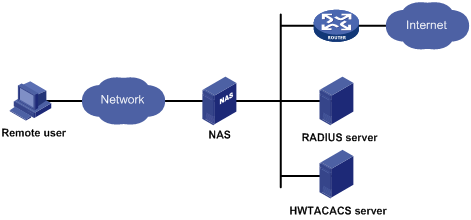
When a user tries to log in to the NAS, use network resources, or access other networks, the NAS authenticates the user. The NAS can transparently pass the user’s authentication, authorization, and accounting information to the servers. The RADIUS and HWTACACS protocols define how a NAS and a remote server exchange user information between them.
In the network shown in Figure 1, there is a RADIUS server and an HWTACACS server. You can choose different servers for different security functions. For example, you can use the HWTACACS server for authentication and authorization, and the RADIUS server for accounting.
You can use AAA to provide only one or two security functions, if desired. For example, if your company only wants employees to be authenticated before they access specific resources, you only need to configure an authentication server. If network usage information is expected to be recorded, you also need to configure an accounting server.
AAA can be implemented through multiple protocols. The router supports using RADIUS and HWTACACS. RADIUS is often used in practice.
RADIUS
Remote Authentication Dial-In User Service (RADIUS) is a distributed information interaction protocol that uses a client/server model. It can protect networks against unauthorized access and is often used in network environments where both high security and remote user access are required.
RADIUS uses UDP as the transport protocol. It uses UDP port 1812 for authentication and UDP port 1813 for accounting.
RADIUS was originally designed for dial-in user access. With the addition of new access methods, RADIUS has been extended to support additional access methods, for example, Ethernet and ADSL. RADIUS provides access authentication and authorization services, and its accounting function collects and records network resource usage information.
Client/server model
The RADIUS client runs on the NASs located throughout the network. It passes user information to designated RADIUS servers and acts on the responses (for example, rejects or accepts user access requests).
The RADIUS server runs on the computer or workstation at the network center and maintains information related to user authentication and network service access. It listens to connection requests, authenticates users, and returns user access control information (for example, rejecting or accepting the user access request) to the clients.
In general, the RADIUS server maintains the following databases: Users, Clients, and Dictionary, as shown in Figure 2.
Figure 2 RADIUS server components
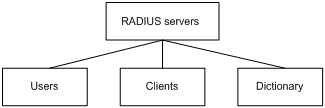
· Users—Stores user information such as the usernames, passwords, applied protocols, and IP addresses.
· Clients—Stores information about RADIUS clients, such as shared keys and IP addresses.
· Dictionary—Stores RADIUS protocol attributes and their values.
Security and authentication mechanisms
Information exchanged between a RADIUS client and the RADIUS server is authenticated with a shared key, which is never transmitted over the network. This enhances the information exchange security. In addition, to prevent user passwords from being intercepted on insecure networks, RADIUS encrypts passwords before transmitting them.
A RADIUS server supports multiple user authentication methods, such as the Password Authentication Protocol (PAP) and Challenge Handshake Authentication Protocol (CHAP) of the Point-to-Point Protocol (PPP). Moreover, a RADIUS server can act as the client of another AAA server to provide authentication proxy services.
RADIUS basic message exchange process
Figure 3 illustrates the interaction of the host, the RADIUS client, and the RADIUS server.
Figure 3 RADIUS basic message exchange process
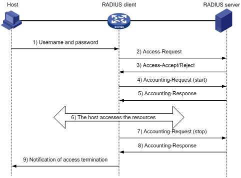
RADIUS operates in the following manner:
1. The host initiates a connection request that carries the user’s username and password to the RADIUS client.
2. Having received the username and password, the RADIUS client sends an authentication request (Access-Request) to the RADIUS server, with the user password encrypted by using the Message-Digest 5 (MD5) algorithm and the shared key.
3. The RADIUS server authenticates the username and password. If the authentication succeeds, the server sends back an Access-Accept message containing the user’s authorization information. If the authentication fails, the server returns an Access-Reject message.
4. The RADIUS client permits or denies the user according to the returned authentication result. If it permits the user, it sends a start-accounting request (Accounting-Request) to the RADIUS server.
5. The RADIUS server returns a start-accounting response (Accounting-Response) and starts accounting.
6. The user accesses the network resources.
7. The host requests the RADIUS client to tear down the connection and the RADIUS client sends a stop-accounting request (Accounting-Request) to the RADIUS server.
8. The RADIUS server returns a stop-accounting response (Accounting-Response) and stops accounting for the user.
9. The user stops access to network resources.
RADIUS packet format
RADIUS uses UDP to transmit messages. It ensures the smooth message exchange between the RADIUS server and the client through a series of mechanisms, including: the timer management mechanism, retransmission mechanism, and slave server mechanism. Figure 4 shows the RADIUS packet format.
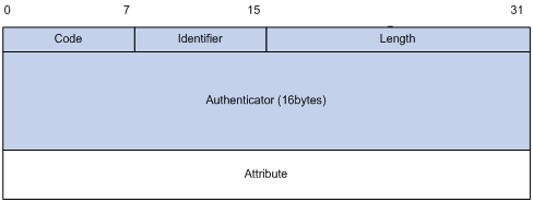
Descriptions of the fields are as follows:
1. The Code field (1 byte long) indicates the type of the RADIUS packet. Table 1 gives the possible values and their meanings.
Table 1 Main values of the Code field
|
Code |
Packet type |
Description |
|
1 |
Access-Request |
From the client to the server. A packet of this type carries user information for the server to authenticate the user. It must contain the User-Name attribute and can optionally contain the attributes of NAS-IP-Address, User-Password, and NAS-Port. |
|
2 |
Access-Accept |
From the server to the client. If all the attribute values carried in the Access-Request are acceptable, that is, the authentication succeeds, the server sends an Access-Accept response. |
|
3 |
Access-Reject |
From the server to the client. If any attribute value carried in the Access-Request is unacceptable, the server rejects the user and sends an Access-Reject response. |
|
4 |
Accounting-Request |
From the client to the server. A packet of this type carries user information for the server to start or stop accounting for the user. The Acct-Status-Type attribute in the packet indicates whether to start or stop the accounting. |
|
5 |
Accounting-Response |
From the server to the client. The server sends a packet of this type to notify the client that it has received the Accounting-Request and has correctly recorded the accounting information. |
2. The Identifier field (1 byte long) is used to match request packets and response packets and to detect duplicate request packets. Request and response packets of the same type have the same identifier.
3. The Length field (2 byte long) indicates the length of the entire packet, including the Code, Identifier, Length, Authenticator, and Attribute fields. Bytes beyond the length are considered padding and are neglected upon reception. If the length of a received packet is less than this length, the packet is dropped. The value of the field is in the range 20 to 4096.
4. The Authenticator field (16 byte long) is used to authenticate replies from the RADIUS server and to encrypt user passwords. There are two types of authenticators: request authenticator and response authenticator.
5. The Attributes field, variable in length, carries the specific authentication, authorization, and accounting information that defines the configuration details of the request or response. This field may contain multiple attributes, each with three sub-fields: Type, Length, and Value.
¡ Type (1 byte long)—Indicates the type of the attribute. It is in the range 1 to 255. Commonly used attributes for RADIUS authentication, authorization and accounting are listed in Table 2.
¡ Length (1 byte long)—Indicates the length of the attribute in bytes, including the Type, Length, and Value fields.
¡ Value (up to 253 bytes)—Value of the attribute. Its format and content depend on the Type and Length fields.
|
No. |
Attribute |
No. |
Attribute |
|
1 |
User-Name |
45 |
Acct-Authentic |
|
2 |
User-Password |
46 |
Acct-Session-Time |
|
3 |
CHAP-Password |
47 |
Acct-Input-Packets |
|
4 |
NAS-IP-Address |
48 |
Acct-Output-Packets |
|
5 |
NAS-Port |
49 |
Acct-Terminate-Cause |
|
6 |
Service-Type |
50 |
Acct-Multi-Session-Id |
|
7 |
Framed-Protocol |
51 |
Acct-Link-Count |
|
8 |
Framed-IP-Address |
52 |
Acct-Input-Gigawords |
|
9 |
Framed-IP-Netmask |
53 |
Acct-Output-Gigawords |
|
10 |
Framed-Routing |
54 |
(unassigned) |
|
11 |
Filter-ID |
55 |
Event-Timestamp |
|
12 |
Framed-MTU |
56-59 |
(unassigned) |
|
13 |
Framed-Compression |
60 |
CHAP-Challenge |
|
14 |
Login-IP-Host |
61 |
NAS-Port-Type |
|
15 |
Login-Service |
62 |
Port-Limit |
|
16 |
Login-TCP-Port |
63 |
Login-LAT-Port |
|
17 |
(unassigned) |
64 |
Tunnel-Type |
|
18 |
Reply-Message |
65 |
Tunnel-Medium-Type |
|
19 |
Callback-Number |
66 |
Tunnel-Client-Endpoint |
|
20 |
Callback-ID |
67 |
Tunnel-Server-Endpoint |
|
21 |
(unassigned) |
68 |
Acct-Tunnel-Connection |
|
22 |
Framed-Route |
69 |
Tunnel-Password |
|
23 |
Framed-IPX-Network |
70 |
ARAP-Password |
|
24 |
State |
71 |
ARAP-Features |
|
25 |
Class |
72 |
ARAP-Zone-Access |
|
26 |
Vendor-Specific |
73 |
ARAP-Security |
|
27 |
Session-Timeout |
74 |
ARAP-Security-Data |
|
28 |
Idle-Timeout |
75 |
Password-Retry |
|
29 |
Termination-Action |
76 |
Prompt |
|
30 |
Called-Station-Id |
77 |
Connect-Info |
|
31 |
Calling-Station-Id |
78 |
Configuration-Token |
|
32 |
NAS-Identifier |
79 |
EAP-Message |
|
33 |
Proxy-State |
80 |
Message-Authenticator |
|
34 |
Login-LAT-Service |
81 |
Tunnel-Private-Group-id |
|
35 |
Login-LAT-Node |
82 |
Tunnel-Assignment-id |
|
36 |
Login-LAT-Group |
83 |
Tunnel-Preference |
|
37 |
Framed-AppleTalk-Link |
84 |
ARAP-Challenge-Response |
|
38 |
Framed-AppleTalk-Network |
85 |
Acct-Interim-Interval |
|
39 |
Framed-AppleTalk-Zone |
86 |
Acct-Tunnel-Packets-Lost |
|
40 |
Acct-Status-Type |
87 |
NAS-Port-Id |
|
41 |
Acct-Delay-Time |
88 |
Framed-Pool |
|
42 |
Acct-Input-Octets |
89 |
(unassigned) |
|
43 |
Acct-Output-Octets |
90 |
Tunnel-Client-Auth-id |
|
44 |
Acct-Session-Id |
91 |
Tunnel-Server-Auth-id |
|
|
NOTE: · The attribute types listed in Table 2 are defined in RFC 2865, RFC 2866, RFC 2867, and RFC 2868. · For more information about commonly used standard RADIUS attributes, see “Commonly used standard RADIUS attributes.” |
Extended RADIUS attributes
The RADIUS protocol features excellent extensibility. Attribute 26 (Vender-Specific), an attribute defined by RFC 2865, allows a vender to define extended attributes to implement functions that the standard RADIUS protocol does not provide.
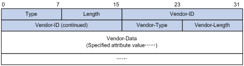
A vendor can encapsulate multiple sub-attributes in the type-length-value (TLV) format in RADIUS packets for extension of applications. As shown in Figure 5, a sub-attribute encapsulated in Attribute 26 consists of the following parts:
· Vendor-ID—Indicates the ID of the vendor. Its most significant byte is 0; the other three bytes contains a code that is compliant to RFC 1700. The vendor ID of H3C is 2011. For more information about the proprietary RADIUS sub-attributes of H3C, see “Proprietary RADIUS sub-attributes of H3C.”
· Vendor-Type—Indicates the type of the sub-attribute.
· Vendor-Length—Indicates the length of the sub-attribute.
· Vendor-Data—Indicates the contents of the sub-attribute.
Figure 5 Segment of a RADIUS packet containing an extended attribute
HWTACACS
HWTACACS is mainly used to provide AAA services for Point-to-Point Protocol (PPP) users, Virtual Private Dial-up Network (VPDN) users, and terminal users. In a typical HWTACACS application, some terminal users need to log in to the router for operations. Working as the HWTACACS client, the NAS sends the username and password of a user to the HWTACACS sever for authentication. After passing authentication and being authorized, the user logs in to the router and performs operations, and the HWTACACS server records the operations that the user performs.
Differences between HWTACACS and RADIUS
HWTACACS and RADIUS both provide authentication, authorization, and accounting services. They have many features in common, like using a client/server model, using shared keys for user information security, and providing flexibility and extensibility. HWTACACS and RADIUS do have differences, as listed in Table 3.
Table 3 Primary differences between HWTACACS and RADIUS
|
HWTACACS |
RADIUS |
|
Uses TCP, providing more reliable network transmission. |
Uses UDP, providing higher transport efficiency. |
|
Encrypts the entire packet except for the HWTACACS header. |
Encrypts only the user password field in an authentication packet. |
|
Protocol packets are complicated and authorization is independent of authentication. Authentication and authorization can be deployed on different HWTACACS servers. |
Protocol packets are simple and the authorization process is combined with the authentication process. |
|
Supports authorization of configuration commands. Which commands a user can use depends on both the user level and AAA authorization. A user can use only commands that are not only of, or lower than, the user level but also authorized by the HWTACACS server. |
Does not support authorization of configuration commands. Which commands a user can use depends on the level of the user and a user can use all the commands of, or lower than, the user level. |
HWTACACS basic message exchange process
The following takes a Telnet user as an example to describe how HWTACACS performs user authentication, authorization, and accounting.
Figure 6 HWTACACS basic message exchange process for a Telnet user
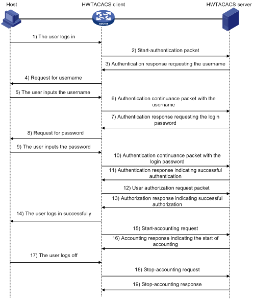
Here is the process:
1. A Telnet user sends an access request to the HWTACACS client.
2. Upon receiving the request, the HWTACACS client sends a start-authentication packet to the HWTACACS server.
3. The HWTACACS server sends back an authentication response to request the username.
4. Upon receiving the response, the HWTACACS client asks the user for the username.
5. The user enters the username.
6. After receiving the username from the user, the HWTACACS client sends the server a continue-authentication packet that carries the username.
7. The HWTACACS server sends back an authentication response, requesting the login password.
8. Upon receipt of the response, the HWTACACS client asks the user for the login password.
9. The user enters the password.
10. After receiving the login password, the HWTACACS client sends the HWTACACS server a continue-authentication packet that carries the login password.
11. The HWTACACS server sends back an authentication response to indicate that the user has passed authentication.
12. The HWTACACS client sends the user authorization request packet to the HWTACACS server.
13. The HWTACACS server sends back the authorization response, indicating that the user is now authorized.
14. Knowing that the user is now authorized, the HWTACACS client pushes its configuration interface to the user.
15. The HWTACACS client sends a start-accounting request to the HWTACACS server.
16. The HWTACACS server sends back an accounting response, indicating that it has received the start-accounting request.
17. The user logs off.
18. The HWTACACS client sends a stop-accounting request to the HWTACACS server.
19. The HWTACACS server sends back a stop-accounting response, indicating that the stop-accounting request has been received.
Domain-based user management
A NAS manages users based on Internet service provider (ISP) domains. An ISP domain has a collection of users.
On a NAS, each user belongs to one ISP domain. A NAS determines the ISP domain a user belongs to by the username entered by the user at login, as shown in Figure 7.
Figure 7 Determine the ISP domain of a user by the username
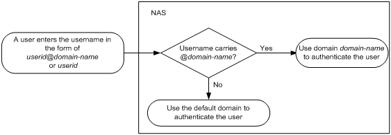
The authentication, authorization, and accounting of a user depends on the AAA methods configured for the domain that the user belongs to. If no specific AAA methods are configured for the domain, the default methods are used. By default, a domain uses local authentication, local authorization, and local accounting.
AAA allows you to manage users based on their access types:
· LAN users—Users on a LAN who must pass 802.1X or MAC address authentication to access the network.
· Login users—Users who want to log in to the router, including SSH users, Telnet users, web users, FTP users, and terminal users.
· Portal users—Users who must pass portal authentication to access the network.
· PPP users—Users who access through PPP.
In addition, AAA provides the following services for login users to enhance the router’s security:
· Command authorization—Enables the NAS to defer to the authorization server to determine whether a command entered by a login user is permitted for the user, making sure that login users execute only commands they are authorized to execute. For more information about command authorization, see Fundamentals Configuration Guide.
· Command accounting—Allows the accounting server to record all commands executed on the router or all authorized commands successfully executed. For more information about command accounting, see Fundamentals Configuration Guide.
· Level switching authentication—Allows the authentication server to authenticate users who perform privilege level switching. As long as passing level switching authentication, users can switch their user privilege levels, without logging out and disconnecting current connections. For more information about user privilege level switching, see Fundamentals Configuration Guide.
You can configure different authentication, authorization, and accounting methods for different users in a domain. For more information about the configuration, see “Configuring AAA methods for ISP domains.”
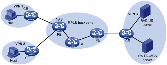
AAA support for MPLS VPNs
In an MPLS L3VPN scenario where clients in different VPNs need to be centrally authenticated, you can deploy AAA across VPNs to enable forwarding RADIUS and HWTACACS packets across MPLS VPNs. With the AAA across VPNs feature, the PE at the left side of the MPLS backbone serves as a NAS and transparently delivers the AAA packets of private users in VPN 1 and VPN 2 to the AAA servers in VPN 3 for centralized authentication, as shown in Figure 8. Authentication packets of private users in different VPNs do not affect each other.
Figure 8 AAA support for VPNs network diagram
|
|
NOTE: Together with the AAA across MPLS L3VPNs feature, you can implement portal authentication across MPLS L3VPNs on MCEs. For more information about MCE, see MPLS Configuration Guide. |
Protocols and standards
The protocols and standards related to AAA, RADIUS, and HWTACACS include:
· RFC 2865, Remote Authentication Dial In User Service (RADIUS)
· RFC 2866, RADIUS Accounting
· RFC 2867, RADIUS Accounting Modifications for Tunnel Protocol Support
· RFC 2868, RADIUS Attributes for Tunnel Protocol Support
· RFC 2869, RADIUS Extensions
· RFC 1492, An Access Control Protocol, Sometimes Called TACACS
RADIUS attributes
Commonly used standard RADIUS attributes
|
No. |
Attribute |
Description |
|
1 |
User-Name |
Name of the user to be authenticated. |
|
2 |
User-Password |
User password for PAP authentication, present only in Access-Request packets in PAP authentication mode. |
|
3 |
CHAP-Password |
Digest of the user password for CHAP authentication, present only in Access-Request packets in CHAP authentication mode. |
|
4 |
NAS-IP-Address |
IP address for the server to identify a client. Usually, a client is identified by the IP address of the access interface of the NAS, namely the NAS IP address. This attribute is present in only Access-Request packets. |
|
5 |
NAS-Port |
Physical port of the NAS that the user accesses. |
|
6 |
Service-Type |
Type of service that the user has requested or type of service to be provided. |
|
7 |
Framed-Protocol |
Encapsulation protocol for framed access. |
|
8 |
Framed-IP-Address |
IP address assigned to the user. |
|
11 |
Filter-ID |
Name of the filter list. |
|
12 |
Framed-MTU |
Maximum transmission unit (MTU) for the data link between the user and NAS. For example, with 802.1X EAP authentication, NAS uses this attribute to notify the server of the MTU for EAP packets, so as to avoid oversized EAP packets. |
|
14 |
Login-IP-Host |
IP address of the NAS interface that the user accesses. |
|
15 |
Login-Service |
Type of the service that the user uses for login. |
|
18 |
Reply-Message |
Text to be displayed to the user, which can be used by the server to indicate, for example, the reason of the authentication failure. |
|
26 |
Vendor-Specific |
Vendor specific attribute. A packet can contain one or more such proprietary attributes, each of which can contain one or more sub-attributes. |
|
27 |
Session-Timeout |
Maximum duration of service to be provided to the user before termination of the session. |
|
28 |
Idle-Timeout |
Maximum idle time permitted for the user before termination of the session. |
|
31 |
Calling-Station-Id |
Identification of the user that the NAS sends to the server. For the LAN access service provided by an H3C device, this attribute carries the MAC address of the user in the format HHHH-HHHH-HHHH. |
|
32 |
NAS-Identifier |
Identification that the NAS uses for indicating itself. |
|
40 |
Acct-Status-Type |
Type of the Accounting-Request packet. Possible values are as follows: · 1—Start · 2—Stop · 3—Interium-Update · 4—Reset-Charge · 7—Accounting-On (Defined in 3GPP, the 3rd Generation Partnership Project) · 8—Accounting-Off (Defined in 3GPP) · 9 to 14—Reserved for tunnel accounting · 15—Reserved for failed |
|
45 |
Acct-Authentic |
Authentication method used by the user. Possible values are as follows: · 1—RADIUS · 2—Local · 3—Remote |
|
60 |
CHAP-Challenge |
CHAP challenge generated by the NAS for MD5 calculation during CHAP authentication. |
|
61 |
NAS-Port-Type |
Type of the physical port of the NAS that is authenticating the user. Possible values are as follows: · 15—Ethernet · 16—Any type of ADSL · 17—Cable (with cable for cable TV) · 201—VLAN · 202—ATM If the port is an ATM or Ethernet one and VLANs are implemented on it, the value of this attribute is 201. |
|
79 |
EAP-Message |
Used for encapsulating EAP packets to allow the NAS to authenticate dial-in users via EAP without having to understand the EAP protocol. |
|
80 |
Message-Authenticator |
Used for authentication and checking of authentication packets to prevent spoofing Access-Requests. This attribute is used when RADIUS supports EAP authentication. |
|
87 |
NAS-Port-Id |
String for describing the port of the NAS that is authenticating the user. |
Proprietary RADIUS sub-attributes of H3C
|
No. |
Sub-attribute |
Description |
|
1 |
Input-Peak-Rate |
Peak rate in the direction from the user to the NAS, in bps. |
|
2 |
Input-Average-Rate |
Average rate in the direction from the user to the NAS, in bps. |
|
3 |
Input-Basic-Rate |
Basic rate in the direction from the user to the NAS, in bps. |
|
4 |
Output-Peak-Rate |
Peak rate in the direction from the NAS to the user, in bps. |
|
5 |
Output-Average-Rate |
Average rate in the direction from the NAS to the user, in bps. |
|
6 |
Output-Basic-Rate |
Basic rate in the direction from the NAS to the user, in bps. |
|
15 |
Remanent_Volume |
Remaining, available total traffic of the connection, in different units for different server types. |
|
20 |
Command |
Operation for the session, used for session control. It can be: · 1—Trigger-Request · 2—Terminate-Request · 3—SetPolicy · 4—Result · 5—PortalClear |
|
24 |
Control_Identifier |
Identification for retransmitted packets. For retransmitted packets of the same session, this attribute must take the same value; for retransmitted packets of different sessions, this attribute may take the same value. The client response of a retransmitted packet must also carry this attribute and the value of the attribute must be the same. For Accounting-Request packets of the start, stop, and interim update types, the Control-Identifier attribute, if present, makes no sense. |
|
25 |
Result_Code |
Result of the Trigger-Request or SetPolicy operation. A value of zero means the operation succeeded; any other value means the operation failed. |
|
26 |
Connect_ID |
Index of the user connection |
|
28 |
Ftp_Directory |
Working directory of the FTP user. For an FTP user, when the RADIUS client acts as the FTP server, this attribute is used to set the FTP directory on the RADIUS client. |
|
29 |
Exec_Privilege |
Priority of the EXEC user |
|
59 |
NAS_Startup_Timestamp |
Startup time of the NAS in seconds, which is represented by the time elapsed after 00:00:00 on Jan. 1, 1970 (UTC). |
|
60 |
Ip_Host_Addr |
User IP address and MAC address carried in authentication and accounting requests, in the format A.B.C.D hh:hh:hh:hh:hh:hh. A space is required between the IP address and the MAC address. |
|
61 |
User_Notify |
Information that needs to be sent from the server to the client transparently |
|
62 |
User_HeartBeat |
Hash value assigned after an 802.1X user passes authentication, which is a 32-byte string. This attribute is stored in the user list on the device and is used for verifying the handshake messages from the 802.1X user. This attribute exists in only Access-Accept and Accounting-Request packets. |
|
140 |
User_Group |
User groups assigned after the SSL VPN user passes authentication. A user may belong to more than one user group. In this case, the user groups are delimited by semi-colons. This attribute is used for cooperation with the SSL VPN device. |
|
141 |
Security_Level |
Security level assigned after the SSL VPN user passes security authentication |
|
201 |
Input-Interval-Octets |
Bytes input within a real-time accounting interval |
|
202 |
Output-Interval-Octets |
Bytes output within a real-time accounting interval |
|
203 |
Input-Interval-Packets |
Packets input within an accounting interval, in the unit set on the device |
|
204 |
Output-Interval-Packets |
Packets output within an accounting interval, in the unit set on the device |
|
205 |
Input-Interval-Gigawords |
Result of bytes input within an accounting interval divided by 4G bytes |
|
206 |
Output-Interval-Gigawords |
Result of bytes output within an accounting interval divided by 4G bytes |
|
207 |
Backup-NAS-IP |
Backup source IP address for sending RADIUS packets |
|
255 |
Product_ID |
Product name |
AAA configuration considerations and task list
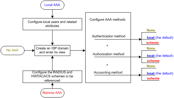
To configure AAA, you must complete these tasks on the NAS:
1. Configure the required AAA schemes.
¡ Local authentication—Configure local users and related attributes, including the usernames and passwords of the users to be authenticated.
¡ Remote authentication—Configure the required RADIUS and HWTACACS schemes. You must configure user attributes on the servers accordingly.
2. Configure AAA methods for the users’ ISP domains.
a. Authentication method—No authentication (none), local authentication (local), or remote authentication (scheme)
b. Authorization method—No authorization (none), local authorization (local), or remote authorization (scheme)
c. Accounting method—No accounting (none), local accounting (local), or remote accounting (scheme)
Figure 9 illustrates the configuration procedure.
Figure 9 AAA configuration procedure
AAA configuration task list
|
Task |
Remarks |
|
|
Required Complete at least one task. |
||
|
Required |
||
|
Optional |
||
|
Required Complete at least one task. |
||
|
Optional |
||
|
Optional |
||
|
|
NOTE: To control access of login users by using AAA methods, you must configure the login authentication mode for the user interfaces as scheme. For more information about the configuration command, see Fundamentals Command Reference. |
Configuring AAA schemes
Configuring local users
To implement local user authentication, authorization, and accounting, you must create local users and configure user attributes on the router. The local users and attributes are stored in the router’s local user database. A local user is uniquely identified by a username. Configurable local user attributes are as follows:
· Service type
The types of the services that the user can use. Local authentication checks the service types of a local user. If none of the service types is available, the user cannot pass authentication.
Service types include FTP, LAN access, Portal, PPP, SSH, Telnet, Terminal, and Web.
· User state
Indicates whether or not a local user can request network services. There are two user states: active and blocked. A user in active state can request network services, but a user in blocked state cannot.
· Maximum number of users using the same local user account
Indicates how many users can use the same local user account for local authentication.
· Validity time and expiration time
Indicates the validity time and expiration time of a local user account. A user must use a local user account that valid to pass local authentication. When some users need to access the network temporarily, you can create a guest account and specify a validity time and an expiration time for the account to control the validity of the account.
· User group
Each local user belongs to a local user group and bears all attributes of the group, such as the password control attributes and authorization attributes. For more information about local user group, see “Configuring user group attributes.”
· Password control attributes
Password control attributes help you control the security of local users’ passwords. Password control attributes include password aging time, minimum password length, and password composition policy.
You can configure a password control attribute in system view, user group view, or local user view, making the attribute effective for all local users, all local users in a group, or only the local user. A password control attribute with a smaller effective range has a higher priority. For more information about password management and global password configuration, see the chapter “Configuring password control.”
· Binding attributes
Binding attributes are used for controlling the scope of users. They are checked during local authentication of a user. If the attributes of a user do not match the binding attributes configured for the local user account, the user cannot pass authentication. Binding attributes include the ISDN calling number, IP address, access port, MAC address, and native VLAN. For more information about binding attributes, see “Configuring local user attributes.” Be cautious when deciding which binding attributes to configure for a local user.
· Authorization attributes
Authorization attributes indicate the rights that a user has after passing local authentication. Authorization attributes include the ACL, PPP callback number, idle cut function, user level, user role, VLAN, and FTP/SFTP work directory. For more information about authorization attributes, see “Configuring local user attributes.”
Every configurable authorization attribute has its definite application environments and purposes. When you configure authorization attributes for a local user, consider which attributes are needed and which are not. For example, for PPP users, you do not need to configure the work directory attribute.
You can configure an authorization attribute in user group view or local user view, making the attribute effective for all local users in the group or for only the local user. The setting of an authorization attribute in local user view takes precedence over that in user group view.
Local user configuration task list
|
Task |
Remarks |
|
Required |
|
|
Optional |
|
|
Displaying and maintaining local users and local user groups |
Optional |
Configuring local user attributes
To configure attributes for a local user:
|
Step |
Command |
Remarks |
|
1. Enter system view. |
system-view |
N/A |
|
2. Set the password display mode for all local users. |
local-user password-display-mode { auto | cipher-force } |
Optional. auto by default, indicating to display the password of a local user in the way defined by the password command. |
|
3. Add a local user and enter local user view. |
local-user user-name |
No local user exists by default. |
|
4. Configure a password for the local user. |
password { cipher | simple } password |
Optional. If you do not configure any password for a local user, the local user does not need to provide any password during authentication, and can pass authentication after entering the correct local user name and passing attribute checks. To achieve higher security, configure a password for each local user. |
|
5. Specify the service types for the local user. |
service-type { ftp | lan-access | { ssh | telnet | terminal } * | portal | ppp | web } |
By default, no service is authorized to a local user. |
|
6. Place the local user to the state of active or blocked. |
state { active | block } |
Optional. When created, a local user is in active state by default, and the user can request network services. |
|
7. Set the maximum number of concurrent users of the local user account. |
access-limit max-user-number |
Optional. By default, there is no limit to the maximum number of concurrent users of a local user account. This limit is not effective for FTP users. |
|
8. Configure the password control attributes for the local user. |
· Set the password aging time: · Set the minimum password length: · Configure the password composition policy: |
Optional. By default, the password control attributes of the user group apply. If the user group has no password control attributes configured, the global settings apply. The global settings include a 90-day password aging time, a minimum 10-character password length, one type number, and one type length. |
|
9. Configure the binding attributes for the local user. |
bind-attribute { call-number call-number [ : subcall-number ] | ip ip-address | location port slot-number subslot-number port-number | mac mac-address | vlan vlan-id } * |
Optional. By default, no binding attribute is configured for a local user. call-number is supported for PPP users. ip, location, mac, and vlan are supported for LAN users. No binding attribute is supported for other types of local users. |
|
10. Configure the authorization attributes for the local user. |
authorization-attribute { acl acl-number | callback-number callback-number | idle-cut minute | level level | user-profile profile-name | user-role { guest | guest-manager | security-audit } | vlan vlan-id | work-directory directory-name } * |
Optional. By default, no authorization attribute is configured for a local user. The router does not support the user-profile keyword. For PPP users, only acl, callback-number, and idle-cut are supported. For LAN and portal users, only acl, idle-cut, and vlan are supported. For SSH, terminal, and Web users, only level is supported. For FTP users, only level and work-directory are supported. For Telnet users, only level and user-role is supported. For other types of local users, no binding attribute is supported. |
|
11. Set the validity time of the local user. |
validity-date time |
Optional. Not set by default. |
|
12. Set the expiration time of the local user. |
expiration-date time |
Optional. Not set by default. |
|
13. Assign the local user to a user group. |
group group-name |
Optional. By default, a local user belongs to the default user group system. |
|
|
NOTE: · On a router supporting the password control feature, local user passwords are not displayed, and the local-user password-display-mode command is not effective. · If you configure the local-user password-display-mode cipher-force command, all existing local user passwords will be displayed in cipher text, regardless of the configuration of the password command. If you also save the configuration and restart the router, all existing local user passwords will always be displayed in cipher text, no matter how you configure the local-user password-display-mode command or the password command. The passwords configured after you restore the display mode to auto by using the local-user password-display-mode auto command, however, are displayed as defined by the password command. · The access-limit command configured for a local user takes effect only in the case of local accounting. · If the user interface authentication mode (set by the authentication-mode command in user interface view) is AAA (scheme), which commands a login user can use after login depends on the privilege level authorized to the user. If the user interface authentication mode is password (password) or no authentication (none), which commands a login user can use after login depends on the level configured for the user interface (set by the user privilege level command in user interface view). For an SSH user using public key authentication, which commands are available depends on the level configured for the user interface. For more information about user interface authentication mode and user interface command level, see Fundamentals Configuration Guide. |
Configuring user group attributes
User groups simplify local user configuration and management. A user group comprises a group of local users and has a set of local user attributes. You can configure local user attributes for a user group to implement centralized user attributes management for the local users in the group. Configurable user attributes include password control attributes and authorization attributes.
By default, every newly added local user belongs to the system default user group system and bears all attributes of the group. To change the user group to which a local user belongs, use the user-group command in local user view.
To configure attributes for a user group:
|
Step |
Command |
Remarks |
|
1. Enter system view. |
system-view |
N/A |
|
2. Create a user group and enter user group view. |
user-group group-name |
N/A |
|
3. Configure password control attributes for the user group. |
· Set the password aging time: · Set the minimum password length: · Configure the password composition policy: |
Optional. By default, the global settings apply. The global settings include a 90-day password aging time, a minimum 10-character password length, one type number, and one type length. |
|
4. Configure the authorization attributes for the user group. |
authorization-attribute { acl acl-number | callback-number callback-number | idle-cut minute | level level | user-profile profile-name | vlan vlan-id | work-directory directory-name } * |
Optional. By default, no authorization attribute is configured for a user group. The router does not support the user-profile keyword. |
|
5. Set the guest attribute for the user group. |
group-attribute allow-guest |
Optional. By default, the guest attribute is not set for a user group, and guest users created by a guest manager through the web interface cannot join the group. |
Displaying and maintaining local users and local user groups
|
Task |
Command |
Remarks |
|
Display local user information. |
display local-user [ idle-cut { disable | enable } | service-type { ftp | lan-access | portal | ppp | ssh | telnet | terminal | web } | state { active | block } | user-name user-name | vlan vlan-id ] [ slot slot-number ] [ | { begin | exclude | include } regular-expression ] |
Available in any view |
|
Display the user group configuration information. |
display user-group [ group-name ] [ | { begin | exclude | include } regular-expression ] |
Available in any view |
Configuring RADIUS schemes
A RADIUS scheme specifies the RADIUS servers that the router can cooperate with and defines a set of parameters that the router uses to exchange information with the RADIUS servers. There may be authentication/authorization servers and accounting servers, or primary servers and secondary servers. The parameters mainly include the IP addresses of the servers, the shared keys, and the RADIUS server type.
RADIUS scheme configuration task list
|
Task |
Remarks |
|
Required |
|
|
Required |
|
|
Specifying the RADIUS accounting servers and the relevant parameters |
Optional |
|
Optional |
|
|
Optional |
|
|
Optional |
|
|
Setting the maximum number of RADIUS request transmission attempts |
Optional |
|
Optional |
|
|
Optional |
|
|
Specifying the source IP address for outgoing RADIUS packets |
Optional |
|
Setting timers for controlling communication with RADIUS servers |
Optional |
|
Optional |
|
|
Optional |
|
|
Configuring interpretation of RADIUS class attribute as CAR parameters |
Optional |
|
Optional |
|
|
Optional |
|
|
Optional |
Creating a RADIUS scheme
Before performing other RADIUS configurations, follow these steps to create a RADIUS scheme and enter RADIUS scheme view:
|
Step |
Command |
Remarks |
|
1. Enter system view. |
system-view |
N/A |
|
2. Create a RADIUS scheme and enter RADIUS scheme view. |
radius scheme radius-scheme-name |
No RADIUS scheme by default |
|
|
NOTE: A RADIUS scheme can be referenced by multiple ISP domains at the same time. |
Specifying the RADIUS authentication/authorization servers
You can specify one primary authentication/authorization server and up to 16 secondary authentication/authorization servers for a RADIUS scheme. When the primary server is not available, a secondary server is used, if any. In a scenario where redundancy is not required, specify only the primary server.
In RADIUS, user authorization information is piggybacked in authentication responses sent to RADIUS clients. It is neither allowed nor needed to specify a separate RADIUS authorization server.
To specify RADIUS authentication/authorization servers for a RADIUS scheme:
|
Step |
Command |
Remarks |
|
1. Enter system view. |
system-view |
N/A |
|
2. Enter RADIUS scheme view. |
radius scheme radius-scheme-name |
N/A |
|
3. Specify RADIUS authentication/authorization servers. |
· Specify the primary RADIUS
authentication/authorization server: · Specify a secondary RADIUS authentication/authorization server: |
Configure at least one command. No authentication/authorization server is specified by default. |
|
|
NOTE: · The IP addresses of the primary and secondary authentication/authorization servers for a scheme must be different from each other. Otherwise, the configuration will fail. · All servers for authentication/authorization and accountings, primary or secondary, must use IP addresses of the same IP version. · You can specify a RADIUS authentication/authorization server as the primary authentication/authorization server for one scheme and as the secondary authentication/authorization server for another scheme at the same time. |
Specifying the RADIUS accounting servers and the relevant parameters
You can specify one primary accounting server and up to 16 secondary accounting servers for a RADIUS scheme. When the primary server is not available, a secondary server is used, if any. When redundancy is not required, specify only the primary server.
By setting the maximum number of real-time accounting attempts for a scheme, you make the router disconnect users for whom no accounting response is received before the number of accounting attempts reaches the limit.
When the router receives a connection teardown request from a host or a connection teardown notification from an administrator, it sends a stop-accounting request to the accounting server. You can enable buffering of non-responded stop-accounting requests to allow the router to buffer and resend a stop-accounting request until it receives a response or the number of stop-accounting attempts reaches the configured limit. In the latter case, the router discards the packet.
To specify RADIUS accounting servers and set relevant parameters for a scheme:
|
Step |
Command |
Remarks |
|
1. Enter system view. |
system-view |
N/A |
|
2. Enter RADIUS scheme view. |
radius scheme radius-scheme-name |
N/A |
|
3. Specify RADIUS accounting servers. |
· Specify the primary RADIUS accounting server: · Specify a secondary RADIUS accounting server: |
Configure at least one command. No accounting server is specified by default. |
|
4. Set the maximum number of real-time accounting attempts. |
retry realtime-accounting retry-times |
Optional. 5 by default. |
|
5. Enable buffering of stop-accounting requests to which no responses are received. |
stop-accounting-buffer enable |
Optional. Enabled by default. |
|
6. Set the maximum number of stop-accounting attempts. |
retry stop-accounting retry-times |
Optional. 500 by default. |
|
|
NOTE: · The IP addresses of the primary and secondary accounting servers must be different from each other. Otherwise, the configuration fails. · All servers for authentication/authorization and accountings, primary or secondary, must use IP addresses of the same IP version. · If you delete an accounting server that is serving users, the router can no longer send real-time accounting requests and stop-accounting requests for the users to that server, or buffer the stop-accounting requests. · You can specify a RADIUS accounting server as the primary accounting server for one scheme and as the secondary accounting server for another scheme at the same time. · RADIUS does not support accounting for FTP users. |
Specifying the shared keys for RADIUS packets
The RADIUS client and RADIUS server use the MD5 algorithm to encrypt packets exchanged between them and use shared keys to verify the packets. They must use the same shared key for the same type of packets.
A shared key configured in this task is for all servers of the same type (accounting or authentication) in the scheme, and has a lower priority than a shared key configured individually for a RADIUS server.
To specify shared keys for RADIUS packets:
|
Step |
Command |
Remarks |
|
1. Enter system view. |
system-view |
N/A |
|
2. Enter RADIUS scheme view. |
radius scheme radius-scheme-name |
N/A |
|
3. Specify a shared key for RADIUS authentication/authorization or accounting packets. |
key { accounting | authentication } [ cipher | simple ] password |
No shared key by default |
|
|
NOTE: A shared key configured on the router must be the same as that configured on the RADIUS server. |
Specifying the VPN to which the servers belongs
After you specify a VPN for a RADIUS scheme, all the authentication/authorization/accounting servers specified for the scheme belong to the VPN. However, if you also specify a VPN when specifying a server for the scheme, the server belongs to the specific VPN.
To specify a VPN for a RADIUS scheme:
|
Step |
Command |
|
1. Enter system view. |
system-view |
|
2. Enter RADIUS scheme view. |
radius scheme radius-scheme-name |
|
3. Specify a VPN for the RADIUS scheme. |
vpn-instance vpn-instance-name |
Setting the supported RADIUS server type
The supported RADIUS server type determines the type of the RADIUS protocol that the router uses to communicate with the RADIUS server. It can be standard or extended:
· Standard—Uses the standard RADIUS protocol, compliant to RFC 2865 and RFC 2866 or later.
· Extended—Uses the proprietary RADIUS protocol of H3C.
When the RADIUS server runs CAMS or iMC, you must set the RADIUS server type to extended. When the RADIUS server runs third-party RADIUS server software, either RADIUS server type applies. For the router to function as a RADIUS server to authenticate login users, you must set the RADIUS server type to standard.
To set the RADIUS server type:
|
Step |
Command |
Remarks |
|
1. Enter system view. |
system-view |
N/A |
|
2. Enter RADIUS scheme view. |
radius scheme radius-scheme-name |
N/A |
|
3. Set the RADIUS server type. |
server-type { extended | standard } |
Optional. standard by default. |
|
|
NOTE: Changing the RADIUS server type will restore the unit for data flows and that for packets that are sent to the RADIUS server to the defaults. |
Setting the maximum number of RADIUS request transmission attempts
Because RADIUS uses UDP packets to transfer data, the communication process is not reliable. RADIUS uses a retransmission mechanism to improve the reliability. If a NAS sends a RADIUS request to a RADIUS server but receives no response after the response timeout timer (defined by the timer response-timeout command) expires, it retransmits the request. If the number of transmission attempts exceeds the specified limit but it still receives no response, it tries to communicate with other RADIUS servers in active state. If no other servers are in active state at the time, it considers the authentication or accounting attempt a failure. For more information about RADIUS server states, see “Setting the status of RADIUS servers.”
To set the maximum number of RADIUS request transmission attempts for a scheme:
|
Step |
Command |
Remarks |
|
1. Enter system view. |
system-view |
N/A |
|
2. Enter RADIUS scheme view. |
radius scheme radius-scheme-name |
N/A |
|
3. Set the maximum number of RADIUS request transmission attempts. |
retry retry-times |
Optional. 3 by default. |
|
|
NOTE: · The maximum number of transmission attempts of RADIUS packets multiplied by the RADIUS server response timeout period cannot be greater than 75 seconds. · For more information about the RADIUS server response timeout period, see “Setting timers for controlling communication with RADIUS servers.” |
Setting the status of RADIUS servers
By setting the status of RADIUS servers to blocked or active, you can control which servers the router will communicate with for authentication, authorization, and accounting or turn to when the current servers are not available anymore. In practice, you can specify one primary RADIUS server and multiple secondary RADIUS servers, with the secondary servers functioning as the backup of the primary servers. Generally, the router chooses servers based on these rules:
· When the primary server is in active state, the router communicates with the primary server. If the primary server fails, the router changes the server’s status to blocked and starts a quiet timer for the server, and then turns to a secondary server in active state (a secondary server configured earlier has a higher priority). If the secondary server is unreachable, the router changes the server’s status to blocked, starts a quiet timer for the server, and continues to check the next secondary server in active state. This search process continues until the router finds an available secondary server or has checked all secondary servers in active state. If the quiet timer of a server expires or an authentication or accounting response is received from the server, the status of the server changes back to active automatically, but the router does not check the server again during the authentication or accounting process. If no server is found reachable during one search process, the router considers the authentication or accounting attempt a failure.
· Once the accounting process of a user starts, the router keeps sending the user’s real-time accounting requests and stop-accounting requests to the same accounting server. If you remove the accounting server, real-time accounting requests and stop-accounting requests for the user cannot be delivered to the server anymore.
· If you remove an authentication or accounting server in use, the communication of the router with the server will soon time out, and the router will look for a server in active state from scratch: it checks the primary server (if any) first and then the secondary servers in the order they are configured.
· When the primary server and secondary servers are all in blocked state, the router communicates with the primary server. If the primary server is available, its status changes to active; otherwise, its status remains to be blocked.
· If one server is in active state and all the others are in blocked state, the router only tries to communicate with the server in active state, even if the server is unavailable.
· After receiving an authentication/accounting response from a server, the router changes the status of the server identified by the source IP address of the response to active if the current status of the server is blocked.
By default, the router sets the status of all RADIUS servers to active. In some cases, however, you may need to change the status of a server. For example, if a server fails, you can change the status of the server to blocked to avoid communication with the server.
To set the status of RADIUS servers in a RADIUS scheme:
|
Step |
Command |
Remarks |
|
1. Enter system view. |
system-view |
N/A |
|
2. Enter RADIUS scheme view. |
radius scheme radius-scheme-name |
N/A |
|
3. Set the status of RADIUS servers. |
· Set the status of the primary RADIUS
authentication/authorization server: · Set the status of the primary RADIUS
accounting server: · Set the status of the secondary RADIUS
authentication/authorization server: · Set the status of the secondary RADIUS
accounting server: |
Optional. active for every server specified in the RADIUS scheme by default. |
|
|
NOTE: · The server status set by the state command cannot be saved to the configuration file. After the router restarts, the status of each server is restored to active. · To display the states of the servers, use the display radius scheme command. |
Setting the username format and traffic statistics units
A username is usually in the format of userid@isp-name, where isp-name represents the name of the ISP domain the user belongs to and is used by the router to determine which users belong to which ISP domains. However, some earlier RADIUS servers cannot recognize usernames that contain an ISP domain name. In this case, the router must remove the domain name of each username before sending the username. You can set the username format on the router for this purpose.
The router periodically sends accounting updates to RADIUS accounting servers to report the traffic statistics of online users. For normal and accurate traffic statistics, make sure that the unit for data flows and that for packets on the router are consistent with those on the RADIUS server.
To set the username format and the traffic statistics units for a RADIUS scheme:
|
Step |
Command |
Remarks |
|
1. Enter system view. |
system-view |
N/A |
|
2. Enter RADIUS scheme view. |
radius scheme radius-scheme-name |
N/A |
|
3. Set the format for usernames sent to the RADIUS servers. |
user-name-format { keep-original | with-domain | without-domain } |
Optional. By default, the ISP domain name is included in a username. |
|
4. Specify the unit for data flows or packets sent to the RADIUS servers. |
data-flow-format { data { byte | giga-byte | kilo-byte | mega-byte } | packet { giga-packet | kilo-packet | mega-packet | one-packet } }* |
Optional. byte for data flows and one-packet for data packets by default. |
|
|
NOTE: · If a RADIUS scheme defines that the username is sent without the ISP domain name, do not apply the RADIUS scheme to more than one ISP domain. Otherwise, users using the same username but in different ISP domains will be considered the same user. · For level switching authentication, the user-name-format keep-original and user-name-format without-domain commands produce the same results; they make sure that usernames sent to the RADIUS server carry no ISP domain name. |
Specifying the source IP address for outgoing RADIUS packets
The source IP address of RADIUS packets that a NAS sends must match the IP address of the NAS configured on the RADIUS server. A RADIUS server identifies a NAS by its IP address. Upon receiving a RADIUS packet, a RADIUS server checks whether the source IP address of the packet is the IP address of any managed NAS. If yes, the server processes the packet. If not, the server drops the packet.
Usually, the source address of outgoing RADIUS packets can be the IP address of the NAS’s any interface that can communicate with the RADIUS server. In some special scenarios, however, you must change the source IP address. For example, if a Network Address Translation (NAT) device is present between the NAS and the RADIUS server, the source IP address of outgoing RADIUS packets must be a public IP address of the NAS. If the NAS is configured with the Virtual Router Redundancy Protocol (VRRP) for stateful failover, the source IP address of outgoing RADIUS packets can be the virtual IP address of the VRRP group that the uplink belongs to.
You can specify a source IP address for outgoing RADIUS packets in RADIUS scheme view for a specific RADIUS scheme, or in system view for all RADIUS schemes whose servers are in a VPN or the public network. Before sending a RADIUS packet, a NAS selects a source IP address in this order:
1. The source IP address specified for the RADIUS scheme.
2. The source IP address specified in system view for the VPN or public network, depending on where the RADIUS server resides.
3. The IP address of the outbound interface specified by the route.
To specify a source IP address for all RADIUS schemes in a VPN or the public network:
|
Step |
Command |
Remarks |
|
1. Enter system view. |
system-view |
N/A |
|
2. Specify a source IP address for outgoing RADIUS packets. |
radius nas-ip { ip-address | ipv6 ipv6-address } [ vpn-instance vpn-instance-name ] |
By default, the IP address of the outbound interface is used as the source IP address. |
To specify a source IP address for a specific RADIUS scheme:
|
Step |
Command |
Remarks |
|
1. Enter system view. |
system-view |
N/A |
|
2. Enter RADIUS scheme view. |
radius scheme radius-scheme-name |
N/A |
|
3. Specify a source IP address for outgoing RADIUS packets. |
nas-ip { ip-address | ipv6 ipv6-address } |
By default, the IP address of the outbound interface is used as the source IP address. |
Setting timers for controlling communication with RADIUS servers
The router uses the following types of timers to control the communication with a RADIUS server:
· Server response timeout timer (response-timeout)—Defines the RADIUS request retransmission interval. After sending a RADIUS request (authentication/authorization or accounting request), the router starts this timer. If the router receives no response from the RADIUS server before this timer expires, it resends the request.
· Server quiet timer (quiet)—Defines the duration to keep an unreachable server in blocked state. If a server is not reachable, the router changes the server’s status to blocked, starts this timer for the server, and tries to communicate with another server in active state. After this timer expires, the router changes the status of the server back to active.
· Real-time accounting timer (realtime-accounting)—Defines the interval at which the router sends real-time accounting packets to the RADIUS accounting server for online users. To implement real-time accounting, the router must periodically send real-time accounting packets to the accounting server for online users.
To set timers for controlling communication with RADIUS servers:
|
Step |
Command |
Remarks |
|
1. Enter system view. |
system-view |
N/A |
|
2. Enter RADIUS scheme view. |
radius scheme radius-scheme-name |
N/A |
|
3. Set the RADIUS server response timeout timer. |
timer response-timeout seconds |
Optional. 3 seconds by default. |
|
4. Set the quiet timer for the servers. |
timer quiet minutes |
Optional. 5 minutes by default. |
|
5. Set the real-time accounting timer. |
timer realtime-accounting minutes |
Optional. 12 minutes by default. |
|
|
NOTE: · For a type of users, the maximum number of transmission attempts multiplied by the RADIUS server response timeout period must be less than the client connection timeout time and must not exceed 75 seconds. Otherwise, stop-accounting messages cannot be buffered, and the primary/secondary server switchover cannot take place. For example, the product of the two parameters must be less than 10 seconds for voice users, and less than 30 seconds for Telnet users because the client connection timeout period for voice users is 10 seconds and that for Telnet users is 30 seconds. · When you configure the maximum number of RADIUS packet transmission attempts and the RADIUS server response timeout period, be sure to take the number of secondary servers into account. If the retransmission process takes too much time, the client connection in the access module may be timed out while the router is trying to find an available server. · When a number of secondary servers are configured, the client connections of access modules that have a short client connection timeout period may still be timed out during initial authentication or accounting, even if the packet transmission attempt limit and server response timeout period are configured with small values. In this case, the next authentication or accounting attempt may succeed because the router has set the state of the unreachable servers to blocked and the time for finding a reachable server is shortened. · Be sure to set the server quiet timer properly. Too short a quiet timer may result in frequent authentication or accounting failures because the router has to repeatedly attempt to communicate with an unreachable server that is in active state. · For more information about the maximum number of RADIUS packet transmission attempts, see “Setting the maximum number of RADIUS request transmission attempts.” |
Configuring RADIUS accounting-on
The accounting-on feature enables a router to send accounting-on packets to the RADIUS server after it reboots, making the server log out users who logged in through the router before the reboot. Without this feature, users who were online before the reboot cannot re-log in after the reboot, because the RADIUS server considers they are already online.
If a router sends an accounting-on packet to the RADIUS server but receives no response, it resends the packet to the server at a particular interval for a specified number of times.
To configure the accounting-on feature for a RADIUS scheme:
|
Step |
Command |
Remarks |
|
1. Enter system view. |
system-view |
N/A |
|
2. Enter RADIUS scheme view. |
radius scheme radius-scheme-name |
N/A |
|
3. Enable accounting-on and configure parameters. |
accounting-on enable [ interval seconds | send send-times ] * |
Disabled by default. The default interval is 3 seconds and the default number of send-times is 5. |
|
|
NOTE: The accounting-on feature requires the cooperation of the H3C CAMS or H3C iMC network management system. |
Configuring the IP address of the security policy server
The core of the H3C EAD solution is integration and cooperation, and the security policy server is the management and control center. Using a collection of software, the security policy server provides functions such as user management, security policy management, security status assessment, security cooperation control, and security event audit.
The NAS checks the validity of received control packets and accepts only control packets from known servers. To use a security policy server that is independent of the AAA servers, you must configure the IP address of the security policy server on the NAS. To implement all EAD functions, configure both the IP address of the iMC security policy server and that of the iMC configuration platform on the NAS.
To configure the IP address of the security policy server for a scheme:
|
Step |
Command |
Remarks |
|
1. Enter system view. |
system-view |
N/A |
|
2. Enter RADIUS scheme view. |
radius scheme radius-scheme-name |
N/A |
|
3. Configure the IP address of the security policy server. |
security-policy-server ip-address |
Not configured by default |
|
|
NOTE: You can specify up to eight security policy servers for a RADIUS scheme. |
Configuring interpretation of RADIUS class attribute as CAR parameters
According to RFC 2865, a RADIUS server assigns the RADIUS class attribute (attribute 25) to a RADIUS client. However, the RFC only requires the RADIUS client to send the attribute to the accounting server on an “as is” basis; it does not require the RADIUS client to interpret the attribute. Some RADIUS servers use the class attribute to deliver the assigned committed access rate (CAR) parameters. In this case, the router must interpret the attribute as the CAR parameters to implement user-based traffic monitoring and controlling.
To configure a router to interpret the RADIUS class attribute as CAR parameters:
|
Step |
Command |
Remarks |
|
1. Enter system view. |
system-view |
N/A |
|
2. Enter RADIUS scheme view. |
radius scheme radius-scheme-name |
N/A |
|
3. Interpret the class attribute as CAR parameters. |
attribute 25 car |
By default, RADIUS attribute 25 is not interpreted as CAR parameters. |
Enabling the trap function for RADIUS
With the trap function, a NAS sends a trap message when either of the following events occurs:
· The status of a RADIUS server changes. If a NAS receives no response to an accounting or authentication request before the specified maximum number of RADIUS request transmission attempts is exceeded, it considers the server unreachable, sets the status of the server to block and sends a trap message. If the NAS receives a response from a RADIUS server that it considers unreachable, the NAS considers that the RADIUS server is reachable again, sets the status of the server to active, and sends a trap message.
· The ratio of the number of failed transmission attempts to the total number of authentication request transmission attempts reaches the threshold. This threshold ranges from 1% to 100% and defaults to 30%. This threshold can only be configured through the MIB.
The failure ratio is generally small. If a trap message is triggered because the failure ratio is higher than the threshold, troubleshoot the configuration on and the communication between the NAS and the RADIUS server.
To enable the trap function for RADIUS:
|
Step |
Command |
Remarks |
|
1. Enter system view. |
system-view |
N/A |
|
2. Enable the trap function for RADIUS. |
radius trap { accounting-server-down | authentication-error-threshold | authentication-server-down } |
Disabled by default |
Enabling the RADIUS listening port of the RADIUS client
Only after you enable the RADIUS listening port of a RADIUS client, can the client receive and send RADIUS packets. If RADIUS is not required, disable the RADIUS listening port to avoid attacks that exploit RADIUS packets.
To enable the RADIUS listening port of a RADIUS client:
|
Step |
Command |
Remarks |
|
1. Enter system view. |
system-view |
N/A |
|
2. Enable the RADIUS listening port of a RADIUS client. |
radius client enable |
Optional. Enabled by default. |
Displaying and maintaining RADIUS
|
Task |
Command |
Remarks |
|
Display the configuration information of a specified RADIUS scheme or all RADIUS schemes. |
display radius scheme [ radius-scheme-name ] [ slot slot-number ] [ | { begin | exclude | include } regular-expression ] |
Available in any view |
|
Display the statistics for RADIUS packets. |
display radius statistics [ slot slot-number ] [ | { begin | exclude | include } regular-expression ] |
Available in any view |
|
Display information about buffered stop-accounting requests for which no responses have been received. |
display stop-accounting-buffer { radius-scheme radius-server-name | session-id session-id | time-range start-time stop-time | user-name user-name } [ slot slot-number ] [ | { begin | exclude | include } regular-expression ] |
Available in any view |
|
Clear RADIUS statistics. |
reset radius statistics [ slot slot-number ] |
Available in user view |
|
Clear the buffered stop-accounting requests for which no responses have been receive. |
reset stop-accounting-buffer { radius-scheme radius-server-name | session-id session-id | time-range start-time stop-time | user-name user-name } [ slot slot-number ] |
Available in user view |
Configuring HWTACACS schemes
|
|
NOTE: You cannot remove the HWTACACS schemes in use or change the IP addresses of the HWTACACS servers in use. |
HWTACACS configuration task list
|
Task |
Remarks |
|
Required |
|
|
Required |
|
|
Optional |
|
|
Specifying the HWTACACS accounting servers and the relevant parameters |
Optional |
|
Required |
|
|
Optional |
|
|
Optional |
|
|
Specifying a source IP address for outgoing HWTACACS packets |
Optional |
|
Setting timers for controlling communication with HWTACACS servers |
Optional |
|
Optional |
Creating an HWTACACS scheme
The HWTACACS protocol is configured on a per scheme basis. Before performing other HWTACACS configurations, follow these steps to create an HWTACACS scheme and enter HWTACACS scheme view:
|
Step |
Command |
Remarks |
|
1. Enter system view. |
system-view |
N/A |
|
2. Create an HWTACACS scheme and enter HWTACACS scheme view. |
hwtacacs scheme hwtacacs-scheme-name |
Not defined by default |
|
|
NOTE: · Up to 16 HWTACACS schemes can be configured. · A scheme can be deleted only when it is not referenced. |
Specifying the HWTACACS authentication servers
You can specify one primary authentication server and up to one secondary authentication server for an HWTACACS scheme. When the primary server is not available, the secondary server is used, if any. In a scenario where redundancy is not required, specify only the primary server.
To specify HWTACACS authentication servers for an HWTACACS scheme:
|
Step |
Command |
Remarks |
|
1. Enter system view. |
system-view |
N/A |
|
2. Enter HWTACACS scheme view. |
hwtacacs scheme hwtacacs-scheme-name |
N/A |
|
3. Specify HWTACACS authentication servers. |
· Specify the primary HWTACACS authentication
server: · Specify a secondary HWTACACS authentication server: |
Configure at least one command. No authentication server is specified by default. |
|
|
NOTE: · An HWTACACS server can function as the primary authentication server of one scheme and as the secondary authentication server of another scheme at the same time. · The IP addresses of the primary and secondary authentication servers cannot be the same. Otherwise, the configuration fails. · You can remove an authentication server only when no active TCP connection for sending authentication packets is using it. |
Specifying the HWTACACS authorization servers
You can specify one primary authorization server and up to one secondary authorization server for an HWTACACS scheme. When the primary server is not available, the secondary server is used, if any. In a scenario where redundancy is not required, specify only the primary server.
To specify HWTACACS authorization servers for an HWTACACS scheme:
|
Step |
Command |
Remarks |
|
1. Enter system view. |
system-view |
N/A |
|
2. Enter HWTACACS scheme view. |
hwtacacs scheme hwtacacs-scheme-name |
N/A |
|
3. Specify HWTACACS authorization servers. |
· Specify the primary HWTACACS authorization
server: · Specify a secondary HWTACACS authorization server: |
Configure at least one command. No authorization server is specified by default. |
|
|
NOTE: · An HWTACACS server can function as the primary authorization server of one scheme and as the secondary authorization server of another scheme at the same time. · The IP addresses of the primary and secondary authorization servers cannot be the same. Otherwise, the configuration fails. · You can remove an authorization server only when no active TCP connection for sending authorization packets is using it. |
Specifying the HWTACACS accounting servers and the relevant parameters
You can specify one primary accounting server and up to one secondary accounting server for an HWTACACS scheme. When the primary server is not available, the secondary server is used, if any. In a scenario where redundancy is not required, specify only the primary server.
When the router receives a connection teardown request from a host or a connection teardown command from an administrator, it sends a stop-accounting request to the accounting server. You can enable buffering of non-responded stop-accounting requests to allow the router to buffer and resend a stop-accounting request until it receives a response or the number of stop-accounting attempts reaches the configured limit. In the latter case, the router discards the packet.
To specify HWTACACS accounting servers and set relevant parameters for an HWTACACS scheme:
|
Step |
Command |
Remarks |
|
1. Enter system view. |
system-view |
N/A |
|
2. Enter HWTACACS scheme view. |
hwtacacs scheme hwtacacs-scheme-name |
N/A |
|
3. Specify HWTACACS accounting servers. |
· Specify the primary HWTACACS accounting server: · Specify a secondary HWTACACS accounting server: |
Configure at least one command. No accounting server is specified by default. |
|
4. Enable the router to buffer stop-accounting requests getting no responses. |
stop-accounting-buffer enable |
Optional. Enabled by default. |
|
5. Set the maximum number of stop-accounting attempts. |
retry stop-accounting retry-times |
Optional. 100 by default. |
|
|
NOTE: · An HWTACACS server can function as the primary accounting server of one scheme and as the secondary accounting server of another scheme at the same time. · The IP addresses of the primary and secondary accounting servers cannot be the same. Otherwise, the configuration fails. · You can remove an accounting server only when no active TCP connection for sending accounting packets is using it. · HWTACACS does not support accounting for FTP users. |
Specifying the shared keys for HWTACACS packets
The HWTACACS client and HWTACACS server use the MD5 algorithm to encrypt packets exchanged between them and use shared keys to verify the packets. They must use the same shared key for the same type of packets.
To specify the shared keys for HWTACACS packets:
|
Step |
Command |
Remarks |
|
1. Enter system view. |
system-view |
N/A |
|
2. Enter HWTACACS scheme view. |
hwtacacs scheme hwtacacs-scheme-name |
N/A |
|
3. Specify the shared keys for HWTACACS authentication, authorization, and accounting packets. |
key { accounting | authentication | authorization } key |
No shared key by default |
|
|
NOTE: A shared key configured on the router must be the same as that configured on the HWTACACS server. |
Specifying the VPN to which the servers belongs
After you specify a VPN for an HWTACACS scheme, all the authentication, authorization, and accounting servers specified for the scheme belong to the VPN. However, if you also specify a VPN when specifying a server for the scheme, the server belongs to the specific VPN.
To specify a VPN for an HWTACACS scheme:
|
Step |
Command |
|
1. Enter system view. |
system-view |
|
2. Enter HWTACACS scheme view. |
hwtacacs scheme hwtacacs-scheme-name |
|
3. Specify a VPN for the HWTACACS scheme. |
vpn-instance vpn-instance-name |
Setting the username format and traffic statistics units
A username is usually in the format of userid@isp-name, where isp-name represents the name of the ISP domain the user belongs to and is used by the router to determine which users belong to which ISP domains. However, some HWTACACS servers cannot recognize usernames that contain an ISP domain name. In this case, the router must remove the domain name of each username before sending the username. You can set the username format on the router for this purpose.
The router periodically sends accounting updates to HWTACACS accounting servers to report the traffic statistics of online users. For normal and accurate traffic statistics, make sure that the unit for data flows and that for packets on the router are consistent with those configured on the HWTACACS servers.
To set the username format and the traffic statistics units for an HWTACACS scheme:
|
Step |
Command |
Remarks |
|
1. Enter system view. |
system-view |
N/A |
|
2. Enter HWTACACS scheme view. |
hwtacacs scheme hwtacacs-scheme-name |
N/A |
|
3. Set the format of usernames sent to the HWTACACS servers. |
user-name-format { keep-original | with-domain | without-domain } |
Optional. By default, the ISP domain name is included in a username. |
|
4. Specify the unit for data flows or packets sent to the HWTACACS servers. |
data-flow-format { data { byte | giga-byte | kilo-byte | mega-byte } | packet { giga-packet | kilo-packet | mega-packet | one-packet } }* |
Optional. byte for data flows and one-packet for data packets by default. |
|
|
NOTE: · If an HWTACACS server does not support a username with the domain name, configure the router to remove the domain name before sending the username to the server. · For level switching authentication, the user-name-format keep-original and user-name-format without-domain commands produce the same results; they make sure that usernames sent to the HWTACACS server carry no ISP domain name. |
Specifying a source IP address for outgoing HWTACACS packets
The source IP address of HWTACACS packets that a NAS sends must match the IP address of the NAS configured on the HWTACACS server. An HWTACACS server identifies a NAS by IP address. Upon receiving an HWTACACS packet, an HWTACACS server checks whether the source IP address of the packet is the IP address of any managed NAS. If yes, the server processes the packet. If not, the server drops the packet.
Usually, the source address of outgoing HWTACACS packets can be the IP address of the NAS’s any interface that can communicate with the HWTACACS server. In some special scenarios, however, you must change the source IP address. For example, if a Network Address Translation (NAT) device is present between the NAS and the HWTACACS server, the source IP address of outgoing HWTACACS packets must be a public IP address of the NAS. If the NAS is configured with the Virtual Router Redundancy Protocol (VRRP) for stateful failover, the source IP address of HWTACACS packets can be the virtual IP address of the VRRP group that the uplink belongs to.
You can specify the source IP address for outgoing HWTACACS packets in HWTACACS scheme view for a specific HWTACACS scheme, or in system view for all HWTACACS schemes whose servers are in a VPN or the public network.
Before sending an HWTACACS packet, a NAS selects a source IP address in this order:
1. The source IP address specified for the HWTACACS scheme.
2. The source IP address specified in system view for the VPN or public network, depending on where the HWTACACS server resides.
3. The IP address of the outbound interface specified by the route.
To specify a source IP address for all HWTACACS schemes of a VPN or the public network:
|
Step |
Command |
Remarks |
|
1. Enter system view. |
system-view |
N/A |
|
2. Specify a source IP address for outgoing HWTACACS packets. |
hwtacacs nas-ip ip-address [ vpn-instance vpn-instance-name ] |
By default, the IP address of the outbound interface is used as the source IP address. |
To specify a source IP address for a specific HWTACACS scheme:
|
Step |
Command |
Remarks |
|
1. Enter system view. |
system-view |
N/A |
|
2. Enter HWTACACS scheme view. |
hwtacacs scheme hwtacacs-scheme-name |
N/A |
|
3. Specify a source IP address for outgoing HWTACACS packets. |
nas-ip ip-address |
By default, the IP address of the outbound interface is used as the source IP address. |
Setting timers for controlling communication with HWTACACS servers
The router uses the following timers to control the communication with an HWTACACS server:
· Server response timeout timer (response-timeout)—Defines the HWTACACS request retransmission interval. After sending an HWTACACS request (authentication, authorization, or accounting request), the router starts this timer. If the router receives no response from the server before this timer expires, it resends the request.
· Server quiet timer (quiet)—Defines the duration to keep an unreachable server in blocked state. If a server is not reachable, the router changes the server’s status to blocked, starts this timer for the server, and tries to communicate with another server in active state. After this timer expires, the router changes the status of the server back to active.
· Real-time accounting timer (realtime-accounting)—Defines the interval at which the router sends real-time accounting updates to the HWTACACS accounting server for online users. To implement real-time accounting, the router must send real-time accounting packets to the accounting server for online users periodically.
To set timers for controlling communication with HWTACACS servers:
|
Step |
Command |
Remarks |
|
1. Enter system view. |
system-view |
N/A |
|
2. Enter HWTACACS scheme view. |
hwtacacs scheme hwtacacs-scheme-name |
N/A |
|
3. Set the HWTACACS server response timeout timer. |
timer response-timeout seconds |
Optional. 5 seconds by default. |
|
4. Set the quiet timer for the primary server. |
timer quiet minutes |
Optional. 5 minutes by default. |
|
5. Set the real-time accounting interval. |
timer realtime-accounting minutes |
Optional. 12 minutes by default. |
|
|
NOTE: Consider the performance of the NAS and the HWTACACS server when you set the real-time accounting interval. A shorter interval requires higher performance. |
Displaying and maintaining HWTACACS
|
Task |
Command |
Remarks |
|
Display configuration information or statistics of the specified or all HWTACACS schemes. |
display hwtacacs [ hwtacacs-server-name [ statistics ] ] [ slot slot-number ] [ | { begin | exclude | include } regular-expression ] |
Available in any view |
|
Display information about buffered stop-accounting requests for which no responses have been received. |
display stop-accounting-buffer hwtacacs-scheme hwtacacs-scheme-name [ slot slot-number ] [ | { begin | exclude | include } regular-expression ] |
Available in any view |
|
Clear HWTACACS statistics. |
reset hwtacacs statistics { accounting | all | authentication | authorization } [ slot slot-number ] |
Available in user view |
|
Clear buffered stop-accounting requests that get no responses. |
reset stop-accounting-buffer hwtacacs-scheme hwtacacs-scheme-name [ slot slot-number ] |
Available in user view |
Configuring AAA methods for ISP domains
You configure AAA methods for an ISP domain by referencing configured AAA schemes in ISP domain view. Each ISP domain has a set of default AAA methods, which are local authentication, local authorization, and local accounting by default and can be customized. If you do not configure any AAA methods for an ISP domain, the router uses the system default AAA methods for authentication, authorization, and accounting of the users in the domain.
Configuration prerequisites
To use local authentication for users in an ISP domain, configure local user accounts (see “Configuring local user attributes”) on the router.
To use remote authentication, authorization, and accounting, create the required RADIUS and HWTACACS schemes as described in “Configuring RADIUS schemes” and “Configuring HWTACACS schemes.”
Creating an ISP domain
In a networking scenario with multiple ISPs, the router may connect users of different ISPs, and users of different ISPs may have different user attributes, such as different username and password structures, different service types, and different rights. To distinguish the users of different ISPs, configure ISP domains, and configure different AAA methods and domain attributes for the ISP domains.
The router can accommodate up to 16 ISP domains, including the system predefined ISP domain system. You can specify one of the ISP domains as the system default domain.
On the router, each user belongs to an ISP domain. If a user provides no ISP domain name at login, the router considers the user belongs to the system default ISP domain.
To create an ISP domain:
|
Step |
Command |
Remarks |
|
1. Enter system view. |
system-view |
N/A |
|
2. Create an ISP domain and enter ISP domain view. |
domain isp-name |
N/A |
|
3. Return to system view. |
quit |
N/A |
|
4. Specify the default ISP domain. |
domain default enable isp-name |
Optional. By default, the default ISP domain is the system predefined ISP domain system. |
|
|
NOTE: To delete the ISP domain that is functioning as the default ISP domain, you must change it to a non-default ISP domain first by using the domain default disable command. |
Configuring ISP domain attributes
To configure ISP domain attributes:
|
Step |
Command |
Remarks |
|
1. Enter system view. |
system-view |
N/A |
|
2. Enter ISP domain view. |
domain isp-name |
N/A |
|
3. Place the ISP domain to the state of active or blocked. |
state { active | block } |
Optional. By default, an ISP domain is in the active state, and users in the domain can request network services. |
|
4. Specify the maximum number of active users in the ISP domain. |
access-limit enable max-user-number |
Optional. No limit by default. |
|
5. Configure the idle cut function. |
idle-cut enable minute [ flow ] |
Optional. Disabled by default. This command is effective for only LAN users, portal users, and PPP users. |
|
6. Configure the self-service server location function. |
self-service-url enable url-string |
Optional. Disabled by default. |
|
7. Define an IP address pool for allocating addresses to PPP users. |
ip pool pool-number low-ip-address [ high-ip-address ] |
Optional. By default, no IP address pool is configured for PPP users. |
|
|
NOTE: A self-service RADIUS server, such as Comprehensive Access Management System (CAMS) or Intelligent Management Center (iMC), is required for the self-service server location function to work. |
Configuring AAA authentication methods for an ISP domain
In AAA, authentication, authorization, and accounting are separate processes. Authentication refers to the interactive authentication process of username/password/user information during an access or service request. The authentication process neither sends authorization information to a supplicant nor triggers any accounting.
AAA supports the following authentication methods:
· No authentication (none)—All users are trusted and no authentication is performed. Generally, do not use this method.
· Local authentication (local)—Authentication is performed by the NAS, which is configured with the user information, including the usernames, passwords, and attributes. Local authentication features high speed and low cost, but the amount of information that can be stored is limited by the hardware.
· Remote authentication (scheme)—The NAS cooperates with a RADIUS or HWTACACS server to authenticate users. Remote authentication features centralized information management, high capacity, high reliability, and support for centralized authentication service for multiple NASs. You can configure local or no authentication as the backup method to be used when the remote server is not available. No authentication can only be configured for LAN users as the backup method of remote authentication.
You can configure AAA authentication to work alone without authorization and accounting. By default, an ISP domain uses the local authentication method.
Before configuring authentication methods, complete the following tasks:
· For RADIUS or HWTACACS authentication, configure the RADIUS or HWTACACS scheme to be referenced first. The local and none authentication methods do not require any scheme.
· Determine the access type or service type to be configured. With AAA, you can configure an authentication method for each access type and service type, limiting the authentication protocols that can be used for access.
· Determine whether to configure an authentication method for all access types or service types.
To configure AAA authentication methods for an ISP domain:
|
Step |
Command |
Remarks |
|
1. Enter system view. |
system-view |
N/A |
|
2. Enter ISP domain view. |
domain isp-name |
N/A |
|
3. Specify the default authentication method for all types of users. |
authentication default { hwtacacs-scheme hwtacacs-scheme-name [ local ] | local | none | radius-scheme radius-scheme-name [ local ] } |
Optional. local by default. |
|
4. Specify the authentication method for LAN users. |
authentication lan-access { local | none | radius-scheme radius-scheme-name [ local | none ] } |
Optional. The default authentication method is used by default. |
|
5. Specify the authentication method for login users. |
authentication login { hwtacacs-scheme hwtacacs-scheme-name [ local ] | local | none | radius-scheme radius-scheme-name [ local ] } |
Optional. The default authentication method is used by default. |
|
6. Specify the authentication method for portal users. |
authentication portal { local | none | radius-scheme radius-scheme-name [ local ] } |
Optional. The default authentication method is used by default. |
|
7. Specify the authentication method for PPP users. |
authentication ppp { hwtacacs-scheme hwtacacs-scheme-name [ local ] | local | none | radius-scheme radius-scheme-name [ local ] } |
Optional. The default authentication method is used by default. |
|
8. Specify the authentication method for privilege level switching. |
authentication super { hwtacacs-scheme hwtacacs-scheme-name | radius-scheme radius-scheme-name } |
Optional. The default authentication method is used by default. |
|
|
NOTE: · The authentication method specified with the authentication default command is for all types of users and has a priority lower than that for a specific access type. · With an authentication method that references a RADIUS scheme, AAA accepts only the authentication result from the RADIUS server. The Access-Accept message from the RADIUS server does include the authorization information, but the authentication process ignores the information. · If you specify the radius-scheme radius-scheme-name local or hwtacacs-scheme hwtacacs-scheme-name local option when you configure an authentication method, local authentication is the backup method and is used only when the remote server is not available. · If you specify only the local or none keyword in an authentication method configuration command, the router has no backup authentication method and performs only local authentication or does not perform any authentication. · If the method for level switching authentication references an HWTACACS scheme, the router uses the login username of a user for level switching authentication of the user by default. If the method for level switching authentication references a RADIUS scheme, the system uses the username configured for the corresponding privilege level on the RADIUS server for level switching authentication, rather than the login username. A username configured on the RADIUS server is in the format of $enablevel$, where level specifies the privilege level to which the user wants to switch. For example, if user user1 of domain aaa wants to switch the privilege level to 3, the system uses $enab3@aaa$ for authentication when the domain name is required and uses $enab3$ for authentication when the domain name is not required. |
Configuring AAA authorization methods for an ISP domain
In AAA, authorization is a separate process at the same level as authentication and accounting. Its responsibility is to send authorization requests to the specified authorization servers and to send authorization information to users after successful authorization. Authorization method configuration is optional in AAA configuration.
AAA supports the following authorization methods:
· No authorization (none)—The NAS performs no authorization exchange. After passing authentication, non-login users can access the network, FTP users can access the root directory of the NAS, and other login users have only the right of Level 0 (visiting).
· Local authorization (local)—The NAS performs authorization according to the user attributes configured for users.
· Remote authorization (scheme)—The NAS cooperates with a RADIUS or HWTACACS server to authorize users. RADIUS authorization is bound with RADIUS authentication. RADIUS authorization can work only after RADIUS authentication is successful, and the authorization information is carried in the Access-Accept message. HWTACACS authorization is separate from HWTACACS authentication, and the authorization information is carried in the authorization response after successful authentication. You can configure local authorization or no authorization as the backup method to be used when the remote server is not available.
Before configuring authorization methods, complete the following tasks:
1. For HWTACACS authorization, configure the HWTACACS scheme to be referenced first. For RADIUS authorization, the RADIUS authorization scheme must be the same as the RADIUS authentication scheme; otherwise, it does not take effect.
2. Determine the access type or service type to be configured. With AAA, you can configure an authorization scheme for each access type and service type, limiting the authorization protocols that can be used for access.
3. Determine whether to configure an authorization method for all access types or service types.
To configure AAA authorization methods for an ISP domain:
|
Step |
Command |
Remarks |
|
1. Enter system view. |
system-view |
N/A |
|
2. Enter ISP domain view. |
domain isp-name |
N/A |
|
3. Specify the default authorization method for all types of users. |
authorization default { hwtacacs-scheme hwtacacs-scheme-name [ local ] | local | none | radius-scheme radius-scheme-name [ local ] } |
Optional. local by default. |
|
4. Specify the command authorization method. |
authorization command { hwtacacs-scheme hwtacacs-scheme-name [ local | none ] | local | none } |
Optional. The default authorization method is used by default. |
|
5. Specify the authorization method for LAN users. |
authorization lan-access { local | none | radius-scheme radius-scheme-name [ local | none ] } |
Optional. The default authorization method is used by default. |
|
6. Specify the authorization method for login users. |
authorization login { hwtacacs-scheme hwtacacs-scheme-name [ local ] | local | none | radius-scheme radius-scheme-name [ local ] } |
Optional. The default authorization method is used by default. |
|
7. Specify the authorization method for portal users. |
authorization portal { local | none | radius-scheme radius-scheme-name [ local ] } |
Optional. The default authorization method is used by default. |
|
8. Specify the authorization method for PPP users. |
authorization ppp { hwtacacs-scheme hwtacacs-scheme-name [ local ] | local | none | radius-scheme radius-scheme-name [ local ] } |
Optional. The default authorization method is used by default. |
|
|
NOTE: · The authorization method specified with the authorization default command is for all types of users and has a priority lower than that for a specific access type. · If you configure an authentication method and an authorization method that use RADIUS schemes for an ISP domain, the RADIUS scheme for authorization must be the same as that for authentication. If the RADIUS authorization configuration is invalid or RADIUS authorization fails, the RADIUS authentication also fails. Whenever RADIUS authorization fails, an error message is sent to the NAS, indicating that the server is not responding. · If you specify the radius-scheme radius-scheme-name local or hwtacacs-scheme hwtacacs-scheme-name [ local | none ] option when you configure an authorization method, local authorization or no authorization is the backup method and is used only when the remote server is not available. · If you specify only the local or none keyword in an authorization method configuration command, the router has no backup authorization method and performs only local authorization or does not perform any authorization. |
Configuring AAA accounting methods for an ISP domain
In AAA, accounting is a separate process at the same level as authentication and authorization. Its responsibility is to send accounting start/update/end requests to the specified accounting server. Accounting is not required, and therefore accounting method configuration is optional.
AAA supports the following accounting methods:
· No accounting (none)—The system does not perform accounting for the users.
· Local accounting (local)—Local accounting is implemented on the NAS. It is for counting and controlling the number of concurrent users who use the same local user account; it does not provide statistics for charging. The maximum number of concurrent users using the same local user account is set by the access-limit command in local user view.
· Remote accounting (scheme)—The NAS cooperates with a RADIUS server or HWTACACS server for accounting of users. You can configure local or no accounting as the backup method to be used when the remote server is not available.
By default, an ISP domain uses the local accounting method.
Before configuring accounting methods, complete the following tasks:
1. For RADIUS or HWTACACS accounting, configure the RADIUS or HWTACACS scheme to be referenced first. The local and none authentication methods do not require any scheme.
2. Determine the access type or service type to be configured. With AAA, you can configure an accounting method for each access type and service type, limiting the accounting protocols that can be used for access.
3. Determine whether to configure an accounting method for all access types or service types.
To configure AAA accounting methods for an ISP domain:
|
Step |
Command |
Remarks |
|
1. Enter system view. |
system-view |
N/A |
|
2. Enter ISP domain view. |
domain isp-name |
N/A |
|
3. Enable the accounting optional feature. |
accounting optional |
Optional. Disabled by default. With the accounting optional feature, the router allows users to use network resources when no accounting server is available or communication with all accounting servers fails. |
|
4. Specify the default accounting method for all types of users. |
accounting default { hwtacacs-scheme hwtacacs-scheme-name [ local ] | local | none | radius-scheme radius-scheme-name [ local ] } |
Optional. local by default. |
|
5. Specify the command accounting method. |
accounting command hwtacacs-scheme hwtacacs-scheme-name |
Optional. The default accounting method is used by default. |
|
6. Specify the accounting method for LAN users. |
accounting lan-access { local | none | radius-scheme radius-scheme-name [ local | none ] } |
Optional. The default accounting method is used by default. |
|
7. Specify the accounting method for login users. |
accounting login { hwtacacs-scheme hwtacacs-scheme-name [ local ] | local | none | radius-scheme radius-scheme-name [ local ] } |
Optional. The default accounting method is used by default. |
|
8. Specify the accounting method for portal users. |
accounting portal { local | none | radius-scheme radius-scheme-name [ local ] } |
Optional. The default accounting method is used by default. |
|
9. Specify the accounting method for PPP users. |
accounting ppp { hwtacacs-scheme hwtacacs-scheme-name [ local ] | local | none | radius-scheme radius-scheme-name [ local ] } |
Optional. The default accounting method is used by default. |
|
|
NOTE: · If you configure the accounting optional command, the limit on the number of local user connections is not effective. · The accounting method specified with the accounting default command is for all types of users and has a priority lower than that for a specific access type. · If you specify the radius-scheme radius-scheme-name local or hwtacacs-scheme hwtacacs-scheme-name local option configured when you configure an accounting method, local accounting is the backup method and is used only when the remote server is not available. · If you specify only the local or none keyword in an accounting method configuration command, the router has no backup accounting method and performs only local accounting or does not perform any accounting. · Accounting is not supported for FTP services. |
Tearing down user connections forcibly
To tear down user connections forcibly:
|
Step |
Command |
Remarks |
|
1. Enter system view. |
system-view |
N/A |
|
2. Tear down AAA user connections forcibly. |
cut connection { access-type { dot1x | mac-authentication | portal } | all | domain isp-name | interface interface-type interface-number | ip ip-address | mac mac-address | ucibindex ucib-index | user-name user-name | vlan vlan-id } [ slot slot-number ] |
Applicable to only LAN access, portal and PPP user connections |
Configuring a NAS ID-VLAN binding
The access locations of users can be identified by their access VLANs. In application scenarios where it is required to identify the access locations of users, configure NAS ID-VLAN bindings on the router. Then, when a user gets online, the router obtains the NAS ID by the access VLAN of the user and sends the NAS ID to the RADIUS server through the NAS-identifier attribute.
To configure a NAS ID-VLAN binding:
|
Step |
Command |
Remarks |
|
1. Enter system view. |
system-view |
N/A |
|
2. Create a NAS ID profile and enter NAS ID profile view. |
aaa nas-id profile profile-name |
You can apply a NAS ID profile to an interface enabled with portal. See the chapter “Configuring portal.” |
|
3. Configure a NAS ID-VLAN binding. |
nas-id nas-identifier bind vlan vlan-id |
By default, no NAS ID-VLAN binding exists. |
Displaying and maintaining AAA
|
Task |
Command |
Remarks |
|
Display the configuration information of a specified ISP domain or all ISP domains. |
display domain [ isp-name ] [ | { begin | exclude | include } regular-expression ] |
Available in any view |
|
Display information about specified or all user connections. |
display connection [ access-type { dot1x | mac-authentication | portal } | domain isp-name | interface interface-type interface-number | ip ip-address | mac mac-address | ucibindex ucib-index | user-name user-name | vlan vlan-id ] [ slot slot-number ] [ | { begin | exclude | include } regular-expression ] |
Available in any view |
AAA configuration examples
RADIUS authentication/authorization for Telnet/SSH users
|
|
NOTE: Configuration of RADIUS authentication and authorization SSH users is similar to that for Telnet users. The following takes Telnet users as an example. |
Network requirements
Configure a CAMS/iMC server to act as the RADIUS server to provide authentication and authorization services for Telnet users. Add an account on the RADIUS server, with the username hello@bbb. Set the privilege level of the user to 3.
Set the shared keys for authentication and authorization exchanges between the router and the RADIUS server to expert and specify the ports for authentication/authorization and accounting as 1812 and 1813 respectively.
Configure the router to include domain names in usernames sent to the RADIUS server.
Figure 10 Network diagram
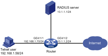
Configuration procedure
1. Configure the RADIUS server (when the RADIUS server runs CAMS):
|
|
NOTE: This example assumes that the RADIUS server runs the CAMS 2.10-R0210. |
# Add an access device.
Log in to the CAMS management platform and select System Management > System Configuration from the navigation tree. In the System Configuration window, click Modify of the Access Device item, and then click Add to enter the Add Access Device window and perform the following configurations:
¡ Specify the IP address of the router as 10.1.1.2.
¡ Set both the shared keys for authenticating authentication and accounting packets to expert.
¡ Select Device Management Service as the service type.
¡ Specify the ports for authentication and accounting as 1812 and 1813 respectively.
¡ Select Extensible Protocol as the protocol type.
¡ Select Standard as the RADIUS packet type.
¡ Click OK.
Figure 11 Add an access device
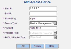
# Add a user for device management.
From the navigation tree, select User Management > User for Device Management, and then in the right pane, click Add to enter the Add Account window and perform the following configurations:
¡ Add a user named hello@bbb and specify the password.
¡ Select Telnet as the service type.
¡ Set the EXEC privilege level to 3. This value identifies the privilege level of the Telnet user after login, which is 0 by default.
¡ Specify the IP address range of the hosts to be managed as 192.168.1.0 to 192.168.1.255.
¡ Click OK.
Figure 12 Add an account for device management
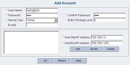
2. Configure the RADIUS server (when the RADIUS server runs iMC)
|
|
NOTE: This example assumes that the RADIUS server runs iMC PLAT 3.20-R2606 and iMC UAM 3.60-E6206. |
# Add an access device.
Log in to the iMC management platform, click the Service tab, and select Access Service > Access Device from the navigation tree to enter the Access Device List page. Then, click Add to enter the Add Access Device page and perform the following configurations:
¡ Set the shared keys for authenticating authentication and accounting packets to expert.
¡ Specify the ports for authentication and accounting as 1812 and 1813 respectively.
¡ Select Device Management Service as the service type.
¡ Select H3C as the access device type.
¡ Select the access device from the device list or manually add the router with the IP address of 10.1.1.2.
¡ Click OK.
|
|
NOTE: The IP address of the access device specified above must be the same as the source IP address of the RADIUS packets sent from the router, which is the IP address of the sending interface by default, or otherwise the IP address specified with the nas-ip or radius nas-ip command. |
Figure 13 Add an access device
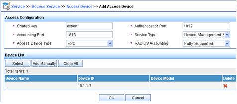
# Add a user for device management.
Log in to the iMC management platform, click the User tab, and select Access User View > Device Mgmt User from the navigation tree to enter the All Access Users page. Then, click Add to enter the Add Device Management User page and perform the following configurations:
¡ Add a user named hello@bbb and specify the password.
¡ Select Telnet as the service type.
¡ Set the EXEC privilege level to 3. This value identifies the privilege level of the Telnet user after login, which is 0 by default.
¡ Specify the IP address range of the hosts to be managed as 10.1.1.0 to 10.1.1.255, and click OK.
|
|
NOTE: The IP address range of the hosts to be managed must contain the IP address of the access device added. |
Figure 14 Add a user for device management
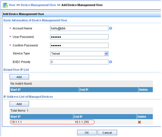
3. Configure the router:
# Configure the IP address of interface GigabitEthernet 4/1/1, through which the Telnet user accesses the router.
<Router> system-view
[Router] interface GigabitEthernet 4/1/1
[Router-GigabitEthernet4/1/1] ip address 192.168.1.70 255.255.255.0
[Router-GigabitEthernet4/1/1] quit
# Configure the IP address of interface GigabitEthernet 4/1/2, through which the router communicates with the server.
[Router] interface gigabitethernet 4/1/2
[Router-GigabitEthernet4/1/2] ip address 10.1.1.2 255.255.255.0
[Router-GigabitEthernet4/1/2] quit
# Enable the Telnet server on the router.
[Router] telnet server enable
# Configure the router to use AAA for Telnet users.
[Router] user-interface vty 0 4
[Router-ui-vty0-4] authentication-mode scheme
[Router-ui-vty0-4] quit
# Create RADIUS scheme rad.
[Router] radius scheme rad
# Specify the primary authentication server, with the IP address of 10.1.1.1, and authentication port of 1812.
[Router-radius-rad] primary authentication 10.1.1.1 1812
# Set the shared key for authentication packets to expert.
[Router-radius-rad] key authentication expert
# Specify the service type for the RADIUS server, which must be extended when the server runs CAMS or iMC.
[Router-radius-rad] server-type extended
# Specify the scheme to include the domain names in usernames to be sent to the RADIUS server.
[Router-radius-rad] user-name-format with-domain
[Router-radius-rad] quit
# Configure the AAA methods for domain bbb. As RADIUS authorization information is sent to the RADIUS client in the authentication response messages, be sure to reference the same scheme for user authentication and authorization.
[Router] domain bbb
[Router-isp-bbb] authentication login radius-scheme rad
[Router-isp-bbb] authorization login radius-scheme rad
[Router-isp-bbb] quit
You can achieve the same result by configuring default AAA methods for all types of users in domain bbb.
[Router] domain bbb
[Router-isp-bbb] authentication default radius-scheme rad
[Router-isp-bbb] authorization default radius-scheme rad
[Router-isp-bbb] quit
When telneting in to the router, a user enters username hello@bbb for authentication using domain bbb.
4. Verify the configuration:
After the above configuration, the Telnet user should be able to telnet to the router, use the configured account to enter the user interface of the router, and access all the commands of level 0 to level 3.
# Use the display connection command to view the connection information on the router.
[Router] display connection
Index=1 ,Username=hello@bbb
IP=192.168.1.58
IPv6=N/A
Total 1 connection(s) matched.
Local authentication/authorization for FTP/Telnet users
|
|
NOTE: Configuration of local authentication and authorization for FTP users is similar to that for Telnet users. The following takes Telnet users as an example. |
Network requirements
As shown in Figure 15, configure the router to perform local authentication and authorization for Telnet users.
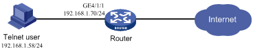
Configuration procedure
1. Configure the router:
# Configure the IP address of interface GigabitEthernet 4/1/1, through which the Telnet user accesses the router.
<Router> system-view
[Router] interface GigabitEthernet 4/1/1
[Router-GigabitEthernet4/1/1] ip address 192.168.1.70 255.255.255.0
[Router-GigabitEthernet4/1/1] quit
# Enable the Telnet server on the router.
[Router] telnet server enable
# Configure the router to use AAA for Telnet users.
[Router] user-interface vty 0 4
[Router-ui-vty0-4] authentication-mode scheme
[Router-ui-vty0-4] quit
# Create local user named telnet.
[Router] local-user telnet
[Router-luser-telnet] service-type telnet
[Router-luser-telnet] password simple aabbccddee
[Router-luser-telnet] quit
# Configure the AAA schemes the ISP domain as local authentication and authorization.
[Router] domain system
[Router-isp-system] authentication login local
[Router-isp-system] authorization login local
[Router-isp-system] quit
2. Verify the configuration:
When telnetting to the router, a user can access the user interface of the router using username telnet@system and correct password.
# Use the display connection command to view the connection information on Router.
[Router] display connection
Index=1 ,Username=telnet@system
IP=192.168.1.58
IPv6=N/A
Total 1 connection(s) matched.
HWTACACS AAA for PPP users
Network requirements
As shown in Figure 16, configure the router to use the HWTACACS server to assign IP addresses and provide authentication, authorization, and accounting services for PPP users. Set the shared keys for authenticating authentication, authorization, and accounting packets exchanged with the server to expert. Configure the router to remove the domain name from a username before sending the username to the HWTACACS server.
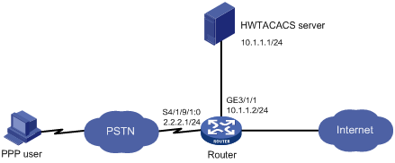
Configuration procedure
1. Configure the HWTACACS server:
# On the HWTACACS server, set the shared keys for packets exchanged with the router to expert. Add the PPP user and specify the password. (Details not shown)
2. Configure the router:
# Create HWTACACS scheme hwtac.
<Router> system-view
[Router] hwtacacs scheme hwtac
# Specify the primary authentication server.
[Router-hwtacacs-hwtac] primary authentication 10.1.1.1 49
# Specify the primary authorization server.
[Router-hwtacacs-hwtac] primary authorization 10.1.1.1 49
# Specify the primary accounting server.
[Router-hwtacacs-hwtac] primary accounting 10.1.1.1 49
# Set the shared keys for authenticating authentication, authorization, and accounting packets to expert.
[Router-hwtacacs-hwtac] key authentication expert
[Router-hwtacacs-hwtac] key authorization expert
[Router-hwtacacs-hwtac] key accounting expert
# Specify the scheme to exclude the domain names from usernames to be sent to the HWTACACS server.
[Router-hwtacacs-hwtac] user-name-format without-domain
[Router-hwtacacs-hwtac] quit
# Apply the AAA schemes to the domain.
[Router] domain bbb
[Router-isp-bbb] authentication ppp hwtacacs-scheme hwtac
[Router-isp-bbb] authorization ppp hwtacacs-scheme hwtac
[Router-isp-bbb] accounting ppp hwtacacs-scheme hwtac
[Router-isp-bbb] ip pool 1 200.1.1.1 200.1.1.99
[Router-isp-bbb] quit
# Configure the default AAA schemes for all types of users.
[Router] domain bbb
[Router-isp-bbb] authentication default hwtacacs-scheme hwtac
[Router-isp-bbb] authorization default hwtacacs-scheme hwtac
[Router-isp-bbb] accounting default hwtacacs-scheme hwtac
[Router-isp-bbb] ip pool 1 200.1.1.1 200.1.1.99
[Router-isp-bbb] quit
# Configure the serial interface.
[Router] interface serial 4/1/9/1:0
[Router-Serial4/1/9/1:0] link-protocol ppp
[Router-Serial4/1/9/1:0] ppp authentication-mode pap domain bbb
[Router-Serial4/1/9/1:0] ip address 2.2.2.1 255.255.255.0
[Router-Serial4/1/9/1:0] remote address pool 1
[Router-Serial4/1/9/1:0] quit
# Configure the GigabitEthernet interface.
[Router] interface GigabitEthernet 3/1/1
[Router-GigabitEthernet3/1/1] ip address 10.1.1.2 255.255.255.0
3. Verify the configuration:
Initiate a PPP connection from the PPP client, and enter the correct username and password. You pass authentication and the PPP client can use the IP address assigned by the router to access the network. You can use the display connection command on the router to view information about the connection.
RADIUS level switching authentication for Telnet users
|
|
NOTE: The RADIUS server in this example runs ACSv4.0. |
Network requirements
As shown in Figure 17, configure the router to:
· Use local authentication for the Telnet user and assign the privilege level of 0 to the user after the user passes authentication.
· Use the RADIUS server for level switching authentication of the Telnet user, and use local authentication as the backup.
Configuration considerations
1. Configure the router to use AAA, particularly, local authentication for Telnet users.
¡ Create ISP domain bbb and configure it to use local authentication for Telnet users.
¡ Create a local user account, configure the password, and assign the privilege level for the user to enjoy after login.
2. On the router, configure the authentication method for user privilege level switching.
¡ Specify to use RADIUS authentication and, if RADIUS authentication is not available, use local authentication for users switching from a lower level to a higher level.
¡ Configure RADIUS scheme rad and assign an IP address to the RADIUS server. Set the shared keys for message exchange and specify that usernames sent to the RADIUS server carry no domain name. Configure the domain to use RADIUS scheme rad for user privilege level switching authentication.
¡ Configure the password for local user privilege level switching authentication.
3. On the RADIUS server, add the username and password for user privilege level switching authentication.
Configuration procedure
1. Configure the router:
# Configure the IP address of GigabitEthernet 4/1/1, through which the Telnet user accesses the router.
<Router> system-view
[Router] interface GigabitEthernet 4/1/1
[Router-GigabitEthernet4/1/1] ip address 192.168.1.70 255.255.255.0
[Router-GigabitEthernet4/1/1] quit
# Configure the IP address of GigabitEthernet 4/1/2, through which the router communicates with the server.
[Router] interface GigabitEthernet 4/1/2
[Router-GigabitEthernet4/1/2] ip address 10.1.1.2 255.255.255.0
[Router-GigabitEthernet4/1/2] quit
# Enable the router to provide Telnet service.
[Router] telnet server enable
# Configure the router to use AAA for Telnet users.
[Router] user-interface vty 0 4
[Router-ui-vty0-4] authentication-mode scheme
[Router-ui-vty0-4] quit
# Specify to use RADIUS authentication for user privilege level switching authentication and, if RADIUS authentication is not available, use local authentication.
[Router] super authentication-mode scheme local
# Create RADIUS scheme rad.
[Router] radius scheme rad
# Specify the IP address of the primary authentication server as 10.1.1.1, and the port for authentication as 1812.
[Router-radius-rad] primary authentication 10.1.1.1 1812
# Set the shared key for authentication packets to expert.
[Router-radius-rad] key authentication expert
# Specify the service type of the RADIUS server as standard.
[Router-radius-rad] server-type standard
# Specify that usernames sent to the RADIUS server carry no domain name.
[Router-radius-rad] user-name-format without-domain
[Router-radius-rad] quit
# Create ISP domain bbb.
[Router] domain bbb
# Configure the AAA methods for domain bbb as local authentication.
[Router-isp-bbb] authentication login local
# Configure the domain to use the RADIUS scheme rad for user privilege level switching authentication.
[Router-isp-bbb] authentication super radius-scheme rad
[Router-isp-bbb] quit
# Create a local Telnet user named test.
[Router] local-user test
[Router-luser-test] service-type telnet
[Router-luser-test] password simple aabbcc
# Configure the user level of the Telnet user after login to 0.
[Router-luser-test] authorization-attribute level 0
[Router-luser-test] quit
# Specify to use RADIUS authentication for user privilege level switching authentication and, if RADIUS authentication is not available, use local authentication.
[Router] super authentication-mode scheme local
# Configure the password for local level switching authentication to 654321.
[Router] super password simple 654321
[Router] quit
2. Configure the RADIUS server:
Add the username and password for user privilege level switching authentication, as shown in Table 4.
Table 4 Add username and passwords for user privilege level switching authentication
|
Username |
Password |
Switching to level |
|
$enab1$ |
pass1 |
1 |
|
$enab2$ |
pass2 |
2 |
|
$enab3$ |
pass3 |
3 |
|
|
NOTE: A username configured on the RADIUS server is in the format of $enablevel$, where level specifies the privilege level to which the user wants to switch. |
Figure 18 Configure the username for privilege level switching (take $enab1$ for example)
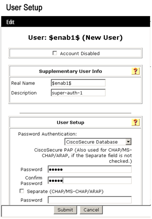
Figure 19 List of the usernames for privilege level switching
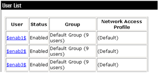
3. Verify the configuration:
After the above configuration, the Telnet user should be able to telnet to the router and use username test@bbb and password aabbcc to enter the user interface of the router, and access all level 0 commands.
<Router> telnet 192.168.1.70
Trying 192.168.1.70 ...
Press CTRL+K to abort
Connected to 192.168.1.70 ...
******************************************************************************
* Copyright (c) 2004-2009 Hangzhou H3C Tech. Co., Ltd. All rights reserved. *
* Without the owner's prior written consent, *
* no decompiling or reverse-engineering shall be allowed. *
******************************************************************************
Login authentication
Username:test@bbb
Password:
<Router> ?
User view commands:
cluster Run cluster command
display Display current system information
ping Ping function
quit Exit from current command view
ssh2 Establish a secure shell client connection
super Set the current user priority level
telnet Establish one TELNET connection
tracert Trace route function
When switching to user privilege level 3, the Telnet user only needs to enter password pass3 as prompted.
<Router> super 3
Password:
User privilege level is 3, and only those commands can be used
whose level is equal or less than this.
Privilege note: 0-VISIT, 1-MONITOR, 2-SYSTEM, 3-MANAGE
If the RADIUS authentication is not available, the Telnet user needs to enter password 654321 as prompted for local authentication.
<Router> super 3
Password: ß Enter the password for RADIUS privilege level switch authentication
Error: Invalid configuration or no response from the authentication server.
Info: Change authentication mode to local.
Password: ß Enter the password for local privilege level switch authentication
User privilege level is 3, and only those commands can be used
whose level is equal or less than this.
Privilege note: 0-VISIT, 1-MONITOR, 2-SYSTEM, 3-MANAGE
RADIUS AAA for portal users
Network requirements
As shown in Figure 20, assign the host a public network IP address or configure the host to automatically obtain an IP address through DHCP. Configure the router to provide direct portal authentication so that the host can access only the portal server before passing portal authentication and can access the Internet after passing portal authentication.
Set the shared keys for authentication and authorization exchanges between the switch and the RADIUS server to expert and specify the ports for authentication/authorization and accounting as 1812 and 1813 respectively.
Configure the router to include domain names in the usernames sent to the RADIUS server.
For the portal user, register a monthly service that charges 120 dollars per month for the usage of up to 120 hours.
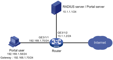
Configuration procedure
|
|
NOTE: · Configure IP addresses for the devices as shown in Figure 20, and make sure that devices can reach each other. · The following describes how to configure the portal server and RADIUS server on the iMC. This example assumes that the RADIUS server runs iMC PLAT 3.20-R2606 and iMC UAM 3.60-E6206. |
1. Configure the RADIUS server:
# Add an access device.
Log in to the iMC management platform, click the Service tab, and select Access Service > Access Device from the navigation tree to enter the Access Device List page. Then, click Add to enter the Add Access Device page and perform the following configurations:
¡ Set the shared keys for authenticating authentication and accounting packets to expert.
¡ Specify the ports for authentication and accounting as 1812 and 1813 respectively.
¡ Select LAN Access Service as the service type.
¡ Select H3C as the access device type.
¡ Select the access device from the device list or manually add the device whose IP address is 10.1.1.2.
¡ Adopt the default settings for other parameters and click OK.
|
|
NOTE: The IP address of the access device specified above must be the same as the source IP address of the RADIUS packets sent from the device, which is the IP address of the outbound interface (the default), or the IP address specified with the nas-ip or radius nas-ip command. |
Figure 21 Add an access device
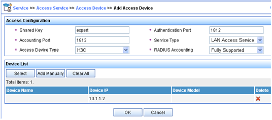
# Add a charging plan.
Click the Service tab, and select Charging Service > Charging Plans from the navigation tree to enter the charging plan configuration page. Then, click Add to enter the Add Charging Plan page and perform the following configurations:
¡ Add a plan named UserAcct.
¡ Select Flat rate as the charging template.
¡ In the Basic Plan Settings field, configure the fixed fee as 120 dollars per month.
¡ In the Service Usage Limit field, set the Usage Threshold to 120 hours, allowing the user to access the Internet for up to 120 hours per month.
¡ Adopt the default settings for other parameters and click OK.
Figure 22 Add a charging policy
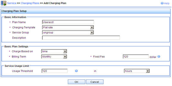
# Add a service.
Click the Service tab, and select Access Service > Service Configuration from the navigation tree to enter the Service Configuration page. Then, click Add to enter the Add Service Configuration page and perform the following configurations:
¡ Add a service named Portal-auth/acct and set the Service Suffix to dm1 which indicates the authentication domain for the portal user. With the service suffix configured, you must configure the usernames to be sent to the RADIUS server to carry the domain name.
¡ Specify UserAcct as the Charging Plan.
¡ Configure other parameters according to the actual situation.
¡ Click OK.
Figure 23 Add a service
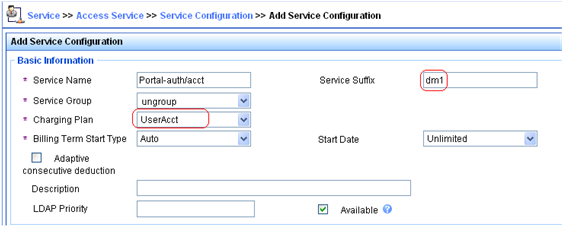
# Add a user.
Click the User tab, and select Access User View > All Access Users from the navigation tree to enter the All Access Users page. Then, click Add to enter the Add Access User page and perform the following configurations:
¡ Select the user or add a user named hello.
¡ Specify the account name as portal and configure the password.
¡ Select the access service Portal-auth/acct.
¡ Configure other parameters accordingly and click OK.
Figure 24 Add an access user account
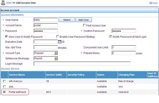
2. Configure the Portal server:
# Configure the Portal server.
Log in to the iMC management platform and click the Service tab. Then, select Portal Service Management > Server from the navigation tree to enter the portal server configuration page, as shown in Figure 25.
¡ Enter the URL address of the portal authentication main page, in the format of http://ip:port/portal, where ip and port are those configured during iMC UAM installation. Usually, the default setting of port 8080 is used.
¡ Click OK.
Figure 25 Portal server configuration
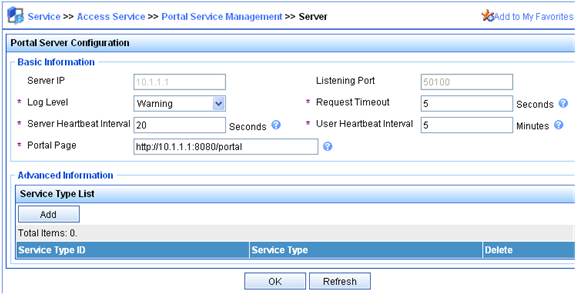
# Configure the IP address group.
Select Portal Service Management > IP Group from the navigation tree to enter the portal IP address group configuration page. Then, click Add to enter the page for adding an IP address group, as shown in Figure 26.
¡ Enter the name Portal_user.
¡ Set the start IP address to 192.168.1.1 and the end IP address to 192.168.1.255. The IP address of Host must be within this IP address group.
¡ Choose not to enable NAT.
¡ Click OK.
Figure 26 Add an IP address group
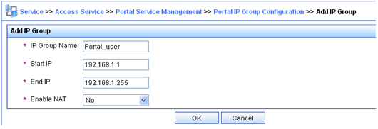
# Add a portal device.
Select Portal Service Management > Device from the navigation tree to enter the portal device configuration page. Then, click Add to enter the page for adding a portal device, as shown in Figure 27.
¡ Enter the device name NAS.
¡ Enter the IP address of the access interface on the device, which is 192.168.1.70.
¡ Enter the key, which is portal, the same as that configured on the router.
¡ Set whether to enable IP address reallocation. Because direct portal authentication is used in this example, select No from the Reallocate IP list.
¡ Click OK.
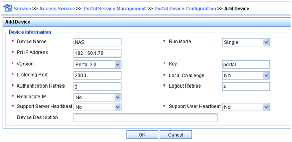
# Associate the portal device with the IP address group.
As shown in Figure 28, in the device list on the portal device configuration page, click the icon in the Port Group Information Management column of device NAS to enter the port group configuration page.
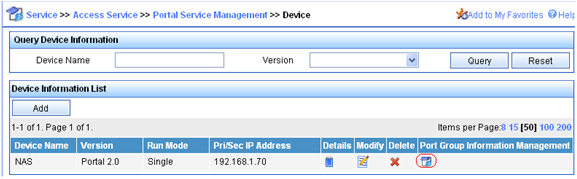
On the port group configuration page, click Add to enter the page for adding a port group, as shown in Figure 29. Perform the following configurations:
¡ Enter the port group name.
¡ Select the configured IP address group. The IP address used by the user to access the network must be within this IP address group.
¡ Use the default settings for other parameters and click OK.
Figure 29 Port group configuration
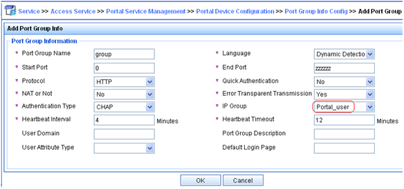
# Select Service Parameters > Validate System Configuration from the navigation tree to validate the configurations.
3. Configure the router:
¡ Configure a RADIUS scheme:
# Create a RADIUS scheme named rs1 and enter its view.
<Router> system-view
[Router] radius scheme rs1
# Set the server type for the RADIUS scheme. When you use the CAMS or iMC server, set the server type to extended.
[Router-radius-rs1] server-type extended
# Specify the primary authentication server and primary accounting server, and configure the keys for communication with the servers.
[Router-radius-rs1] primary authentication 10.1.1.1
[Router-radius-rs1] primary accounting 10.1.1.1
[Router-radius-rs1] key authentication expert
[Router-radius-rs1] key accounting expert
# Specify the scheme to include the domain names in usernames to be sent to the RADIUS server.
[Router-radius-rs1] user-name-format with-domain
[Router-radius-rs1] quit
¡ Configure an authentication domain:
# Create an ISP domain named dm1 and enter its view.
[Router] domain dm1
# Configure the ISP domain to use RADIUS scheme rs1.
[Router-isp-dm1] authentication portal radius-scheme rs1
[Router-isp-dm1] authorization portal radius-scheme rs1
[Router-isp-dm1] accounting portal radius-scheme rs1
[Router-isp-dm1] quit
# Configure dm1 as the default ISP domain for all users. Then, if a user enters a username without any ISP domain at login, the authentication and accounting methods of the default domain will be used for the user.
[Router] domain default enable dm1
¡ Configure portal authentication
# Configure the portal server.
[Router] portal server newpt ip 10.1.1.1 key portal port 50100 url http://10.1.1.1:8080/portal
# Enable portal authentication on the interface connecting the host.
[Router] interface GigabitEthernet 3/1/1
[Router–GigabitEthernet3/1/1] portal server newpt method layer3
[Router–GigabitEthernet3/1/1] quit
4. Verify the configuration:
The user can initiate portal authentication by using the H3C iNode client or by accessing a web page. All the initiated web requests will be redirected to the portal authentication page at http://10.1.1.1:8080/portal. Before passing portal authentication, the user can access only the authentication page. After passing portal authentication, the user can access the Internet.
# After the user passes portal authentication, view the portal user information on the router.
[Router] display portal user interface GigabitEthernet 3/1/1
Index:19
State:ONLINE
SubState:NONE
ACL:NONE
Work-mode:stand-alone
MAC IP Vlan Interface
---------------------------------------------------------------------
0015-e9a6-7cfe 192.168.1.58 0 GigabitEthernet 3/1/1
On interface GigabitEthernet 3/1/1:total 1 user(s) matched, 1 listed.
# View the connection information on the router.
[Router] display connection
Index=20 ,Username=portal@dm1
IP=192.168.1.58
IPv6=N/A
MAC=00-15-E9-A6-7C-FE
Total 1 connection(s) matched.
Troubleshooting AAA
Troubleshooting RADIUS
Symptom 1
User authentication/authorization always fails.
Analysis
1. A communication failure exists between the NAS and the RADIUS server.
2. The username is not in the format of userid@isp-name or the ISP domain for the user authentication is not correctly configured on the NAS.
3. The user is not configured on the RADIUS server.
4. The password entered by the user is incorrect.
5. The RADIUS server and the NAS are configured with different shared key.
Solution
Check that:
1. The NAS and the RADIUS server can ping each other.
2. The username is in the userid@isp-name format and the ISP domain for the user authentication is correctly configured on the NAS.
3. The user is configured on the RADIUS server.
4. The correct password is entered.
5. The same shared key is configured on both the RADIUS server and the NAS.
Symptom 2
RADIUS packets cannot reach the RADIUS server.
Analysis
1. The NAS and the RADIUS server cannot communicate with each other.
2. The NAS is not configured with the IP address of the RADIUS server.
3. The UDP ports for authentication/authorization and accounting are not correct.
4. The port numbers of the RADIUS server for authentication, authorization and accounting are being used by other applications.
Solution
Check that:
1. The communication links between the NAS and the RADIUS server work well at both physical and link layers.
2. The IP address of the RADIUS server is correctly configured on the NAS.
3. UDP ports for authentication/authorization/accounting configured on the NAS are the same as those configured on the RADIUS server.
4. The port numbers of the RADIUS server for authentication, authorization and accounting are available.
Symptom 3
A user is authenticated and authorized, but accounting for the user is not normal.
Analysis
1. The accounting port number is not correct.
2. Configuration of the authentication/authorization server and the accounting server are not correct on the NAS. For example, one server is configured on the NAS to provide all the services of authentication/authorization and accounting, but in fact the services are provided by different servers.
Solution
Check that:
1. The accounting port number is correctly set.
2. The authentication/authorization server and the accounting server are correctly configured on the NAS.
Troubleshooting HWTACACS
Similar to RADIUS troubleshooting. See “Troubleshooting RADIUS.”
