- Released At: 21-01-2020
- Page Views:
- Downloads:
- Table of Contents
- Related Documents
-
H3C LSUM1SDNB0 SDN automation module
1 Identifier
The module identifier LSUM1SDNB0 is in the upper right corner of the front panel.
2 About the module
The LSUM1SDNB0 is an SDN automation module integrated with server components required for ADCampus solutions, including controller, authentication, and address assignment components. It can centrally monitor modules, fan trays, power supplies, and environment and adjust power consumptions. It is plug and play and can be automatically deployed on small and medium-sized campus networks, eliminating the need to install physical servers.
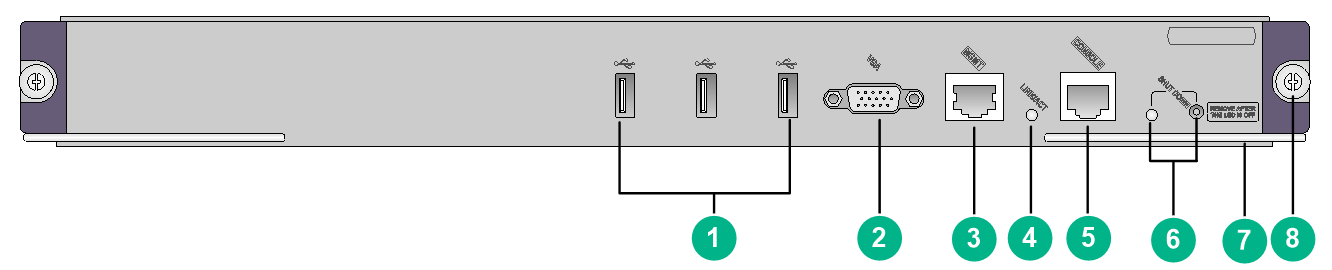
Figure 1 LSUM1SDNB0 front panel
|
(1) USB ports (3 in total) |
(2) VGA connector |
|
(3) Management Ethernet port |
(4) Management Ethernet port LED (LINK/ACT) |
|
(5) Console port (CONSOLE) |
(6) Shutdown LED and button (SHUTDOWN) |
|
(7) Ejector lever |
(8) Captive screw |
3 Specifications
Table 1 Module specifications
|
Item |
Specifications |
|
Hard disk |
480GB SSD |
|
Memory |
Two memory slots Standard configuration: 64 GB (two 32GB memory bars) |
|
Dimensions (H × W × D) |
40 × 399 × 355 mm (1.57 × 15.71 × 13.98 in) |
|
Weight |
3.25 kg (7.17 lb) |
|
Power consumption |
106 to 126 W |
|
Hot swapping |
Not supported |
|
Ports |
· 3 × USB 2.0 ports (used by technical support for debugging only) · 1 × VGA connector · 1 × 10/100/1000BASE-T management Ethernet port · 1 × console port (used by technical support for debugging only) |
|
Ambient temperature |
· Operating: 0°C to 45°C (32°F to 113°F) · Storage: –40°C to +70°C (–40°F to +158°F) |
|
Ambient humidity |
· Operating: 5% RH to 95% RH, noncondensing · Storage: 5% RH to 95% RH, noncondensing |
|
|
NOTE: · To verify the compatibility of the module with the software release you are using, see the release notes. · For information about transceiver modules and cables available for the module, see the modules and transceiver modules compatibility matrixes for the device. |
Table 2 10/100/1000BASE-T management Ethernet port specifications
|
Item |
Specification |
|
Standard |
802.3, 802.3u, and 802.3ab |
|
Auto-MDI/MDIX |
Supported |
|
Cable |
Category 5 or above twisted pair cable |
|
Transmission distance |
100 m (328.08 ft) |
|
Rate and duplex mode |
10/100/1000 Mbps, full-duplex |
4 LEDs
Table 3 LED description
|
LED |
Status |
Description |
|
10/100/1000BASE-T management Ethernet port LED (LINK/ACT) |
Steady green |
A 10/100/1000M link is present on the port. |
|
Flashing green |
The port is sending or receiving data at 10/100/1000 Mbps. |
|
|
Off |
No link is present on the port. |
|
|
Shutdown LED (SHUTDOWN) |
Steady green |
The module is operating. |
|
Flashing green |
The module is being shut down. You can shut down the module only after the LED turns off. |
|
|
Off |
The module is not operating. |
5 Installing and removing the module
|
|
CAUTION: · Wear a reliably grounded ESD wrist strap or ESD gloves when installing and removing the module. · Do not touch the components on the module. |
The module can be installed in a horizontal or vertical slot. When installing the module in a horizontal slot, make sure its component side faces up. When installing the module in a vertical slot, make sure its component side faces left.
The installation and removal procedures are the same for horizontal and vertical slots. The following procedures install and remove the module in a horizontal slot.
5.1 Installing the module
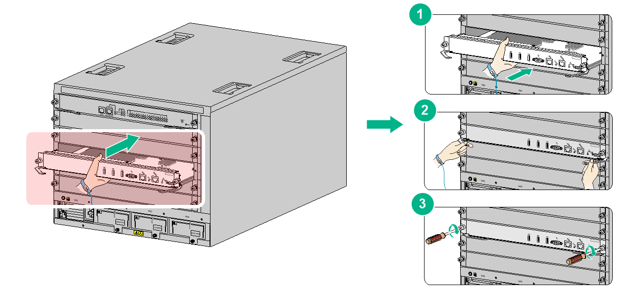
1. Face the front panel of the device. Remove the filler panel from the target slot.
This example installs the module in slot 3 on an S10504 switch.
2. Place the module on a workbench with component side facing up. Open the ejector levers of the module.
3. Gently push the module into the slot along the guide rails.
4. Close the ejector levers and make sure the module makes close contact with the backplane.
5. Use a Phillips screwdriver to fasten the captive screws on the module.
Figure 2 Installing the module
5.2 Removing the module
|
|
IMPORTANT: Before removing the module, press the shutdown button on the module for a minimum of 2 seconds until the shutdown LED flashes green. You can remove the module only after the shutdown LED turns off. |
To remove the module:
1. Use a Phillips screwdriver to loosen the captive screws on the module until all pressure is released.
2. Simultaneously open the ejector levers of the module to disengage the module connector from the backplane. Then pull the module gently out of the slot along the guide rails.
3. Place the removed module on an anti-static workbench or put it in an anti-static bag, with the component side facing up.
4. If you are not to install a new module, install a filler panel in the slot to prevent dust and ensure good ventilation in the device.
6 Software upgrade
For information about upgrading the software, see the release notes for the module.
Copyright © 2019 New H3C Technologies Co., Ltd.
The information in this document is subject to change without notice.
