| Title | Size | Downloads |
|---|---|---|
| H3C 25G_100G Ethernet Solutions for Campus Networks White Paper-6W100-book.pdf | 1.72 MB |
- Table of Contents
- Related Documents
-
|
|
|
H3C 25G/100G Ethernet Solutions for |
|
Campus Networks White Paper |
|
|
|
|
Copyright © 2021 New H3C Technologies Co., Ltd. All rights reserved.
No part of this manual may be reproduced or transmitted in any form or by any means without prior written consent of New H3C Technologies Co., Ltd.
Except for the trademarks of New H3C Technologies Co., Ltd., any trademarks that may be mentioned in this document are the property of their respective owners.
The information in this document is subject to change without notice.
Gradual popularization of Wi-Fi 6
Wide application of 4K HD videos
Enterprises moving to the cloud
Bandwidth upgrade solutions for campus networks
Common 25G/100G transceiver modules
H3C 25GE/100GE products for campus networks
25G SFP28 transceiver module and cables
100G QSFP28 transceiver modules and cables
Medium and large enterprises or campus networks
IP central/sub-control network at a radio and television broadcast station
About the 25G/100G Ethernet
Technical background
On the current campus networks, the uplink bandwidth is typically 10G from the access layer to the distribution layer, and 40G from the distribution layer to the core layer. The emergence of new applications, such as the gradual popularization of Wi-Fi 6, wide application of 4K high-definition videos, and a large number of enterprise applications moving to the cloud, is posing increasingly high requirements on the bandwidth of campus networks. The existing 10G/40G networks can no longer meet the demand. With the benefits of high bandwidth, high density, low cost, and low power, the 25G/100G upgrade solution will drive campus networks towards higher performance and flexibility.
Gradual popularization of Wi-Fi 6
Wi-Fi 6 (802.11ax) is the latest generation of Wi-Fi technology, offering a theoretical maximum transmission rate of 9.6 Gbps. This technology provides high speed and bandwidth, and network capacity with low latency and will greatly improve user experience. This technology has seen fast deployment in recent years (large-scale construction has been conducted in 2020), and an increasing number of devices begin to support Wi-Fi 6. In addition, applications such as 4K high-definition videos, virtual reality (VR), augmented reality (AR), and Internet of Things (loT) also promote Wi-Fi 6 deployment and development. The huge access layer data traffic brought by Wi-Fi 6 users demands higher uplink and downlink network bandwidths.
Wide application of 4K HD videos
The typical 4K resolution 4096×2160 can provide more than 8.8 million pixels, more than four times the resolution than 1080p. Currently 4K has been increasingly used in video conference, HD live streaming, and HD movie and TV scenarios. However, with a data size of 50 MB for each video frame, the data amount of a 4K video reaches over 1.5 GB per second, putting great pressure on network bandwidth. The 10G ports of the current radio and television IP media system can no longer meet the network bandwidth demand (transport of uncompressed 4K videos requires a network bandwidth greater than 10 Gbps).
Enterprises moving to the cloud
Enterprise on the cloud enables flexible and agile management, saves hardware costs, improves working efficiency, and facilitates maintenance. It has become a new network development trend. However, it also poses higher requirements on network bandwidth, delay, and packet loss rate because all data access and maintenance as well as online meeting and data sharing are conducted over the network. A high-performance network must be set up to reduce transmission time, improve efficiency, and enhance enterprise competitiveness.
Bandwidth upgrade solutions for campus networks
In addition to network bandwidth and quality, take the following into consideration for upgrading bandwidth for a campus network:
· Costs—Save costs as much as possible while improving network bandwidth performance
· Compatibility—Make sure the upgraded network is compatible with the existing devices, transceiver modules, and cables.
· Port density—Devices with high port density can provide more uplink and downlink interfaces.
· Power consumption per unit bandwidth—Devices with lower power consumption per unit bandwidth can reduce power consumption of network operations.
40G/100G and 25G/100G solutions are available for network bandwidth upgrade. With the advantages of low upgrade cost, good compatibility, high port density, and low power consumption per unit bandwidth, the 25G/100G solution prevails currently.
40G/100G solution
The 40G/100G solution upgrades the link bandwidth between the access layer and the distribution layer from 10G to 40G, and the link bandwidth between the distribution layer and the core layer from 40G to 100G.
When upgrading the link between the access layer and the distribution layer, you can add additional 10G links for high-density 10G network deployment, increasing the overall network bandwidth to 40G. However, new data links require not only a large number of transceiver modules and optical fibers but also a large number of ports. A lot of new devices might be needed. This will make the network very complicated and difficult to maintain.
If you replace all 10G links with 40G links, the number of links is the same as before, but the devices and transceiver modules need to be replaced at one time. You might need to re-wire the cables because of the limited transmission distance of multimode optical fibers. The upgrade cost is high.
The solution has also the following disadvantages:
· Poor compatibility with transceiver modules—The 40G QSFP+ ports are not compatible with 10G SFP+ transceiver modules. You must replace all 10G transceiver modules.
· Low port density—40G devices have a low port density. You must purchase more devices, which takes up more space in the equipment room.
· High power consumption per unit bandwidth—Each 40G transceiver module uses four 10 Gbps channels.
The 40G/100G solution is not good in terms of upgrade cost and transceiver module compatibility, and has been gradually replaced by the 25G/100G solution.
25G/100G solution
The 25G/100G solution upgrades the link bandwidth between the access layer and the distribution layer from 10G to 25G, and the link bandwidth between the distribution layer and the core layer from 40G to 100G. After the release of the IEEE 25G standard, this solution has been quickly recognized by many companies for its advantages of low cost, low power consumption, and high density. In a 2018 report, Electronic Design predicted that campus networks and data center networks will develop towards 25G and 100G technologies instead of 40G.
The 25G/100G solution has the following advantages.
Lower upgrade cost
The 25G/100G solution is more cost effective than the 40G/100G solution.
· Optical fiber reuse—Effectively reduces the expenses on optical fibers while increasing network bandwidth.
· High port density—25G devices have a higher port density.
· Good compatibility with transceiver modules—25G SFP28 and 100G QSFP28 ports are compatible with existing 10G SFP+ and 40G QSFP+ transceiver modules. The upgrade can be carried out step by step, to reduce the initial investment.
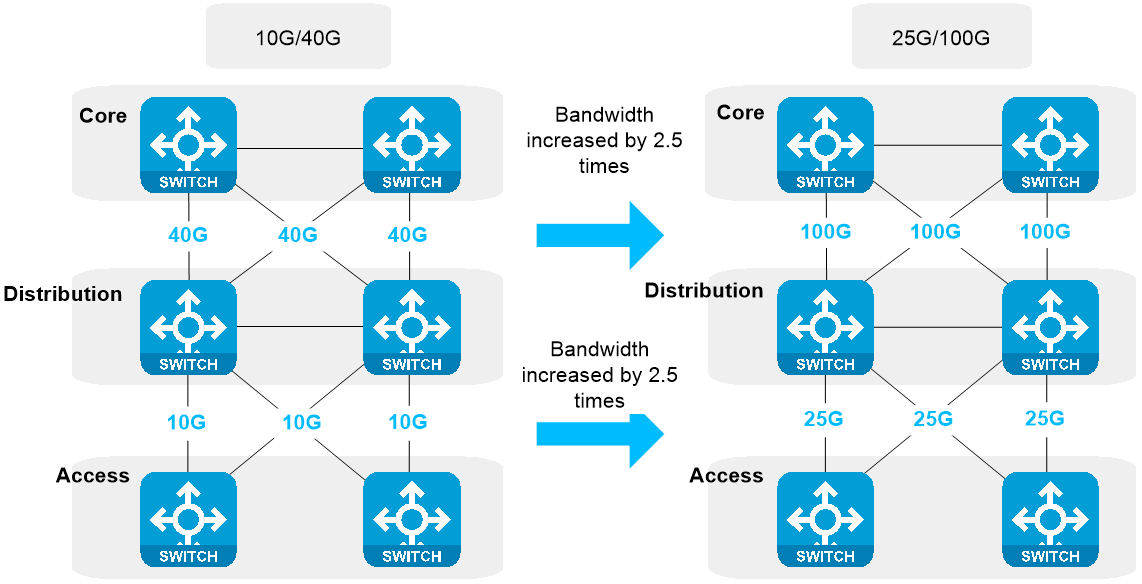
Improved network bandwidth
The 25G/100G solution increases the data link bandwidth between the access layer and the distribution layer and between the distribution layer and the core layer by 2.5 times without compromising the uplink and downlink bandwidth convergence ratio and user experience. The 40G/100G solution can cause changes in the convergence ratio, possibly requiring you to redesign the network architecture.
Figure 1 Network bandwidth increased by 2.5 times
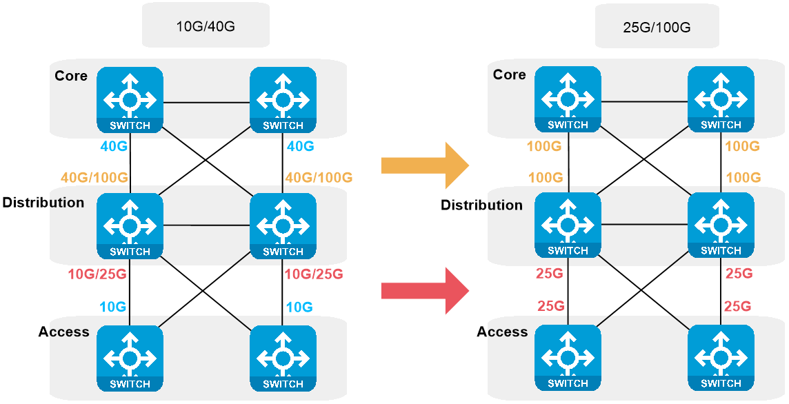
Good compatibility with transceiver modules
25G SFP28 (MSA specification SFF 8431) transceiver modules and 10G SFP+ (MSA specification SFF 8431) transceiver modules use the same form factor. The 25G ports support also 10G transceiver modules, and can auto-negotiate to 10 Gbps.
40G QSFP+ (MSA specification SFF 8436) transceiver modules and 100G QSFP28 (MSA specification SFF 8665) transceiver modules use the same form factor. The 100G ports support also 40G transceiver modules, and can auto-negotiate to 40 Gbps.
The 25G/100G solution has better transceiver module compatibility. During the network upgrade process, you can upgrade the devices first, and then replace the transceiver modules.
Figure 2 Upgrading transceiver modules after upgrading the devices
Optical fiber reuse
The optical fibers used on the 10G/40G network can continue to be used on the 25G/100G network, which saves you from rewiring for the network and facilitates network upgrade.
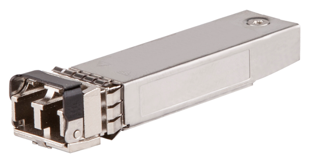
Both 25G SFP28 transceiver modules and 10G SFP+ transceiver modules use LC connectors. The single-mode and multi-mode optical fibers used on 10G networks can continue to be used on 25G networks within the allowed maximum transmission distance.
Figure 3 LC connectors
Both 40G QSFP+ transceiver modules and 100G QSFP28 transceiver modules support MPO or LC connectors, and provide similar transmission distance. Single-mode and multi-mode fibers used on 40G networks can continue to be used on 100G networks.
Figure 4 MPO connector
Table 1 Max transmission distance of H3C transceiver modules
|
Optical fiber type |
10G transceiver modules |
25G transceiver modules |
40G transceiver modules |
100G transceiver modules |
|
9 µm SMF (LC connector) |
80 km (49.71 miles) |
10 km (6.21 miles) |
40 km (24.86 miles) |
40 km (24.86 miles) |
|
62.5 µm OM3 MMF (LC connector) |
33 m (108.27 ft) |
70 m (229.66 ft) |
N/A |
N/A |
|
50 µm OM4 MMF (LC connector) |
300 m (984.25 ft) |
100 m (328.08 ft) |
350 m (1148.29 ft) |
100 m (328.08 ft) |
|
50 µm OM4 MMF (MPO connector) |
N/A |
N/A |
400 m (1312.34 ft) |
300 m (984.25 ft) |
Reduced power consumption per unit bandwidth
The 25G/100G network solution can reduce the network operation cost remarkably. Take the transceiver modules with a maximum transmission distance of 10 km (6.21 miles) as an example. Compared with 10G transceiver modules, the 25G transceiver modules improve the bandwidth by 1.5 times with only a 50% increase in power consumption, reducing the power consumption per unit bandwidth slightly. Compared with 40G transceiver modules, the 100G transceiver modules improve the bandwidth by 1.5 times without an increase in power consumption, reducing the power consumption per unit bandwidth significantly.
Table 2 Power consumption of 10G/25G/40G/100G transceiver modules with a maximum transmission distance of 10 km (6.21 miles)
|
Item |
10G transceiver module |
25G transceiver module |
40G transceiver module |
100G transceiver module |
|
Channels |
1*10 G |
1*25 G |
4*10 G |
4*25 G |
|
Power consumption |
1 W |
1.5 W |
3.5 W |
3.5 W |
Unchanged port density
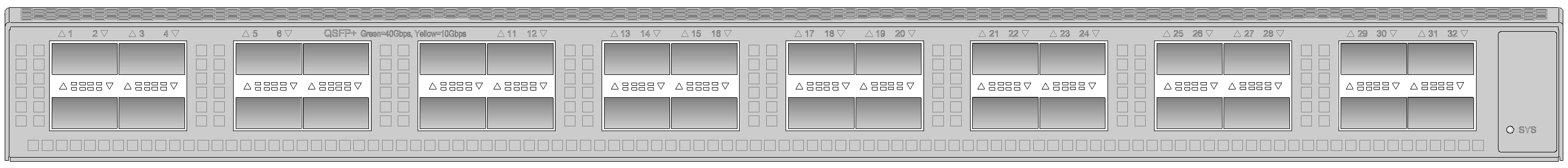
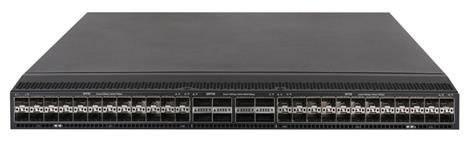
The 25G/100G network devices offer the same high port density as 10G network devices and can provide 48+8 ports, while devices with all ports operating at 40 Gbps can offer only a maximum of 32 ports.
Figure 5 S6550XE-56HF-HI (48*25G+8*100G) front panel
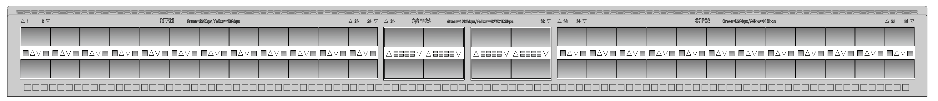
Figure 6 S6800-32Q (32*40G) front panel
25G/100G key technologies
25G standards
Table 3 provides the IEEE standards for 25G SFP28 transceiver modules. As defined in the standards, 25G SFP28 transceiver modules can use a single mode fiber (SMF), multimode fiber (MMF), or passive cable to establish data links. Thanks to technologies such as Serdes, FEC and CDR, the SFP28 transceiver modules can provide reliable transmission at 25 Gbps on a single channel.
Table 3 IEEE 25G standards
|
Standard |
Interface type |
Cable type |
Max transmission distance |
|
IEEE P802.3by |
25GBASE-CR |
Passive cable |
5 m (16.40 ft) |
|
25GBASE-SR |
MMF |
100 m (328.08 ft) |
|
|
IEEE P802.3cc |
25GBASE-LR |
SMF |
10 km (6.21 miles) |
|
25GBASE-ER |
SMF |
40 km (24.86 miles) |
SerDes
SerDes is the short name for Serializer/Deserializer. Serializer is also called SerDes sender (TX), and deserializer is also called SerDes receiver (Rx). SerDes is the mainstream high-speed serial point-to-point communication mode. The serializer serializes and transmits the received data to the deserializer at the peer end. The deserializer at the receiving end reconstructs these serialized bit streams into data and then delivers them to the receiver for use.
Figure 7 SerDes technology
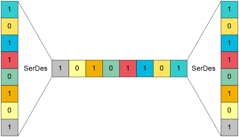
The SerDes technology is not only used for on-board communication between PCIE, SATA, SWITCH and PHY chips, but also used for communication between devices connected by optical fibers and cables. The mainstream 25G SerDes technology offers a transmission rate of 25 Gbps on a single channel, which is 2.5 times over the previous generation 10G SerDes technology. The higher the single channel rate, the lower the power consumption per unit bandwidth. In addition, transceiver modules with fewer channels lower the requirements for cabling.
Table 4 Data rate and transmission channels of common network ports
|
Interface type |
Clock rate |
Channels |
Data rate |
|
1 GbE |
1.25 Ghz |
1 |
1 Gbps |
|
10 GbE |
10.31 Ghz |
1 |
10 Gbps |
|
25 GbE |
25.78 Ghz |
1 |
25 Gbps |
|
40 GbE |
10.31 Ghz |
4 |
40 Gbps |
|
100 GbE |
25.78 Ghz |
4 |
100 Gbps |
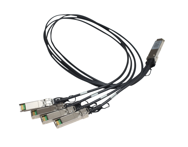
Based on this technology, the SFP28 transceiver module achieves a data rate of 25 Gbps on a single channel. The current mainstream 100G QSFP28 transceiver module provides a data rate of 25 Gbps on four SerDes channels. You can use a breakout cable to connect one 100G QSFP28 port to four 25G SFP28 ports.
FEC
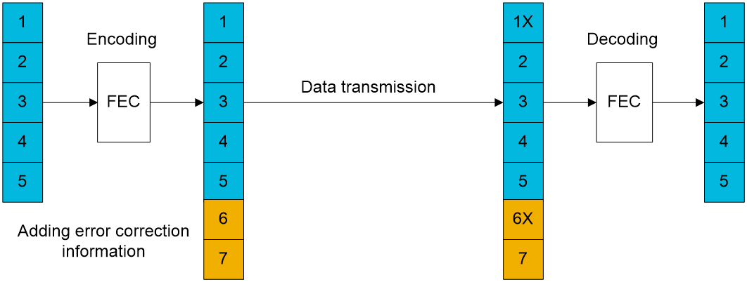
Forward error correction (FEC), as defined in the IEEE RS-FEC 802.3bj-2014 standard, adds error correction information to the data message at the data transmitting end. The receiver uses the error correction information to correct bit errors generated during the packet transmission process. This technology can effectively reduce the error rate on the transmission channel, improve the signal quality, and extend the physical medium transmission distance to the maximum, but it also brings some transmission latency.
Figure 8 FEC
The BASE-R FEC and RS-FEC modes are available.
· As defined in IEEE CLAUSE 74, BASE-R FEC is mainly used for 10GBASE-KR, 40GBASE-KR4, 40GBASE-CR4, and 100GBASE-CR10 PHYs.
· As defined in IEEE CLAUSE 108, RS-FEC is mainly used for 25GBASE-CR, 25GBASE-CR-S, 25GBASE-KR, 25GBASE-KR-S, and 25GBASE-SR PHYs. As defined in IEEE CLAUSE 91, RS-FEC is mainly used for 100G BASE-CR4, 100G BASE-KR4, and 100G BASE-SR4 PHYs.
Table 5 FEC modes for 25G standards
|
Physical medium |
Interface name |
FEC mode |
|
Optical fiber |
25GBASE-SR |
RS-FEC |
|
Copper cable |
25GBASE-CR |
FEC or RS-FEC |
|
Copper cable |
25GBASE-CR-S |
BASE-R FEC or disabled |
|
Electronic backplane |
25GBASE-KR |
BASE-R FEC or RS-FEC |
|
Electronic backplane |
25GBASE-KR-S |
BASE-R FEC or disabled |
|
Twisted pair cable |
25GBASE-T |
N/A |
The IEEE standards define two types of backplanes and cable interfaces. The short-distance interfaces with "-S" in their names use high-quality backplanes or cables, and can minimize the signal transmission delay for short-distance transmission without using FEC. The standard interfaces without "-S" in their names are allowed to use low-cost cables and backplanes for long-distance transmission with FEC enabled.
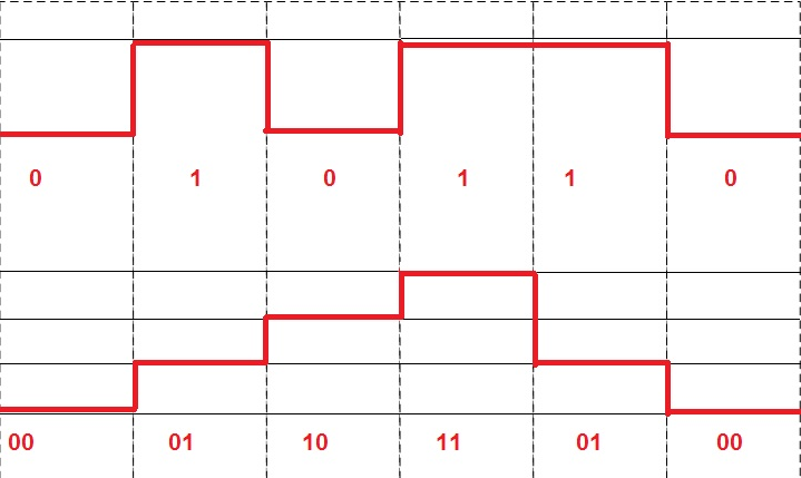
PAM4
4-level pulse amplitude modulation (PAM4), a currently popular high-level modulation method, is increasingly used in high-speed interconnection. Before PAM4, the non-return-to-zero (NRZ) modulation method was mostly used, in which data is encoded as a series of fixed voltage levels (low=0, high=1), each level cycle transmitting 1-bit logic information. With the growth of transmission rate, NRZ modulation lags in terms of cost, photoelectric conversion bandwidth, and external interference, and fails to keep pace with the development of high-performance networks.
The PAM4 modulation method uses four different signal levels 00, 01, 10, and 11 to transmit data, and each level cycle represents 2-bit logic information. To transmit same signals, the baud rate of data modulated by PAM4 is only half of NRZ. A low baud rate reduces the requirements of transceiver modules for components such as transceiver modules, improving cost efficiency. The PAM4 technology enables the transceiver module to provide a transmission rate up to 53.125 bps per channel, which greatly improves the transceiver module performance. Currently the PAM4 technology has been used on 100G QSFP28 transceiver modules.
As shown in Figure 9, NRZ uses two voltage levels 0 and 1. PAM4 uses four voltage levels 00, 01, 10, and 11.
Figure 9 Voltage levels of NRZ and PAM4
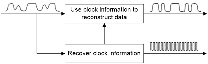
CDR
The transceiver module at the receiving end can use clock and data recovery (CDR) to recover clock information from the received serial data stream, and use the clock information to decode the transmitted data, which ensures data stability and reliability. This technology can reduce the influence of external interference on data, decrease signal phase errors, improve the received signal quality, and lower the requirements for cabling. Transceiver modules with a high transmission rate and long transmission distance, such as 10G transceiver modules with a transmission distance of 40 km (24.86 miles) or 80 km (49.71 miles) and 25G and 100G transceiver modules, all use CDR.
Figure 10 CDR technology
Common 25G/100G transceiver modules
Table 6 Common 25G/100G transceiver modules
H3C 25GE/100GE products for campus networks
Distribution layer products
Fixed-port switches
Table 7 Fixed-port switches at the distribution layer
|
Product series |
Product model |
Ports |
|
S6550XE-HI switch series |
S6550XE-56HF-HI |
48 × 25G SFP28 ports and 8 × 100G QSFP28 ports |
The S6550XE-HI series is a set of new-generation, high-performance, high-port density, and high-security 25G fixed-port Layer 3 Ethernet switches. It uses the industry-leading ASIC technology, provides rich management and security features, and supports IPv4/IPv6 dual stack management and forwarding, routing protocols such as RIP, OSFP, BGP, and ISIS, static routing, and MPLS.
The S6550XE-HIs are ideal 25G switches for campus networks and the IP media system at radio and TV broadcast stations.
· On a campus network, the S6550XE-HI switches can be deployed at the distribution layer or used as core devices for small and medium-sized enterprises. On a MAN or industrial network, they can provide 25G downlink interfaces and 100G uplink interfaces.
· In the IP media central/sub-control system at radio and TV broadcast stations, the S6550XE-HI switches can be used as sub-control switches to increase the access layer bandwidth to 25 Gbps and use 100G uplink interfaces to connect to the central control core switches.
Figure 11 S6550XE-56HF-HI switch
Modular switches
An S10500X modular switch can provide more 25G ports by installing SFP28 optical interface modules.
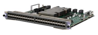
· An LSUM1YGS24CSSH0 SFP28 optical interface module provides twenty-four 25G SFP28 ports and four 100G QSFP28 ports.
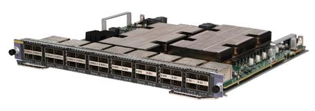
· An LSUM1YGS48XSH0 SFP28 optical interface module provides forty-eight 25G SFP28 ports. You can also select a 100G interface module for the device to provide 100G uplink ports. For the available 100G interface modules, see Table 10.
Table 8 25G SFP28 optical interface modules applicable to modular switches at the distribution layer
|
25G SFP28 optical interface module |
Ports |
Applicable switch models |
|
LSUM1YGS24CSSH0 |
· 24 × 25G SFP28 ports · 4 × 100G QSFP28 ports |
S10500X switch series |
|
LSUM1YGS48XSH0 |
48 × 25G SFP28 ports |
Figure 12 LSUM1YGS24CSSH0 interface module
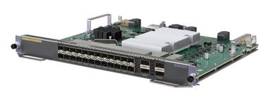
Figure 13 LSUM1YGS48XSH0 interface module
Access layer products
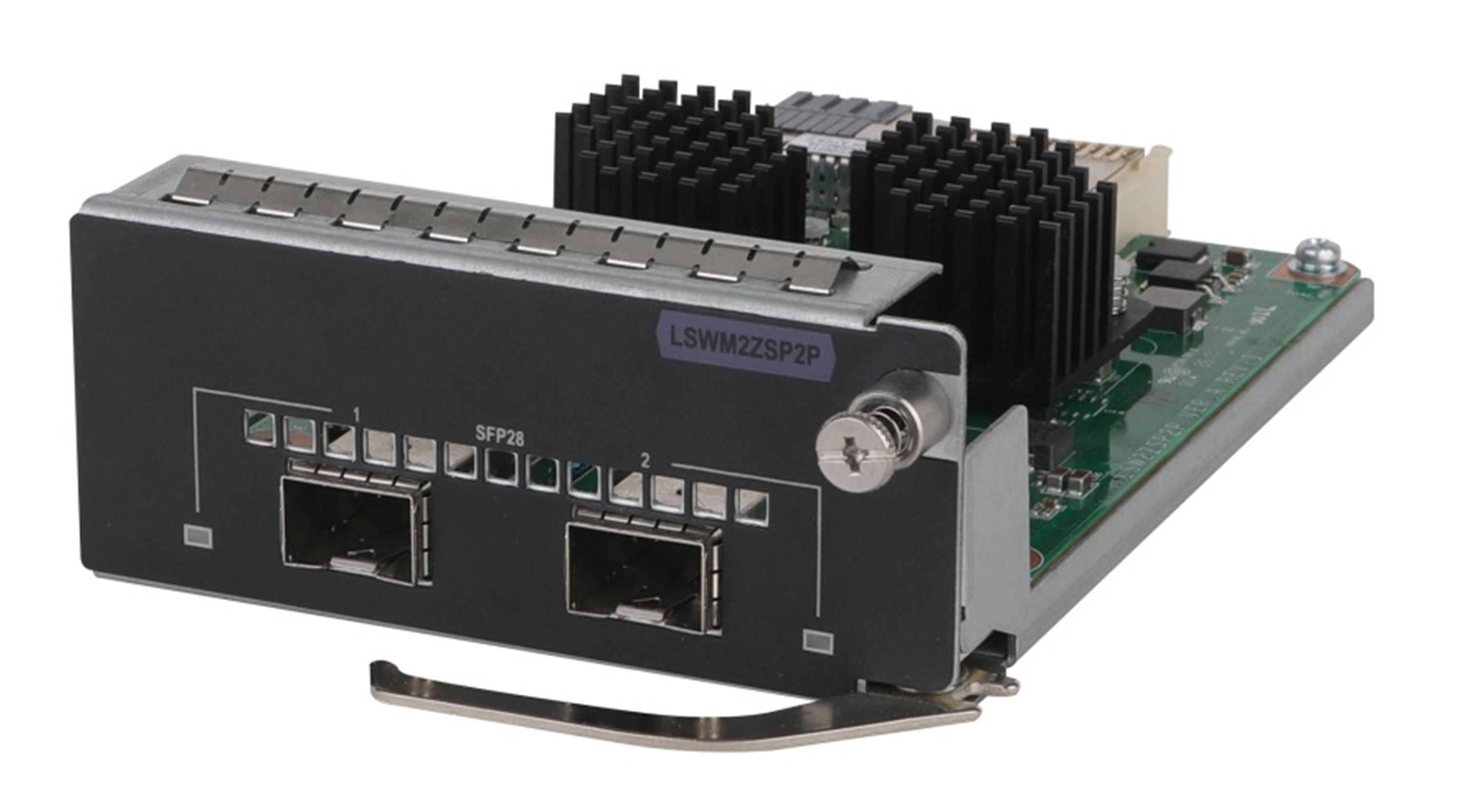
An access layer product can provide two 25G SFP28 uplink ports by installing an LSWM2ZSP2P interface module, which eliminates the need to replace access layer devices and saves the upgrade cost.
Table 9 25G SFP28 optical interface modules applicable to access layer products
|
25G SFP28 optical interface module |
Ports |
Applicable products |
|
LSWM2ZSP2P |
2 × 25G SFP28 ports |
· S6520X-SI multi-rate Ethernet switch series ¡ Downlink—5G/2.5G/1000/100BASE-T auto-sensing Ethernet ports ¡ Uplink—One interface module slot · S5560X-EI Ethernet switch series ¡ Downlink—10/100/1000BASE-T auto-sensing ports or GE SFP ports ¡ Uplink—Four SFP+ ports and one interface module slot |
Figure 14 LSWM2ZSP2P interface module
Core layer products
The S10500X and S12500G-AF modular switches can provide multiple 100G ports by installing QSFP28 optical interface modules.
Table 10 describes the QSFP28 optical interface modules applicable to core layer switches. These interface modules provide different 100G ports. Select one for the device as required.
Table 10 QSFP28 optical interface modules applicable to core layer products
|
Product series |
Product model |
Ports |
Applicable device |
|
100G QSFP28 optical interface module |
LSUM1CGS8SH0 |
8 × 100G QSFP28 ports |
S10500X switch series |
|
LSUM1CGS20XSH0 |
20 × 100G QSFP28 ports |
||
|
LSUM1CGS32XSH0 |
32 × 100G QSFP28 ports |
||
|
LSXM1CGQ8TD2 |
8 × 100G QSFP28 ports |
S12500G-AF switch series |
|
|
LSXM1CGQ18TE2 |
18 × 100G QSFP28 ports |
||
|
LSXM1CGQ18TD2 |
18 × 100G QSFP28 ports |
||
|
LSXM1CGQ36TE2 |
36 × 100G QSFP28 ports |
Figure 15 100G QSFP28 optical interface module (LSUM1CGS32XSH0)
25G/100G transceiver modules
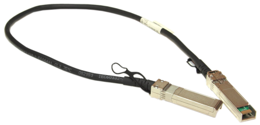
25G SFP28 transceiver module and cables
Table 11 SFP28 transceiver modules
|
Transceiver module model |
Central wavelength (nm) |
Connector |
Fiber diameter and type |
Modal bandwidth (MHz*km) |
Transmission distance |
|
|
|
SFP-25G-SR-MM850 |
850 |
LC |
50/125 µm MMF |
2000 |
With FEC disabled: 30 m (98.43 ft) With FEC enabled: 70 m (229.66 ft) |
|
4700 |
With FEC disabled: 40 m (131.23 ft) With FEC enabled: 100 m (328.08 ft) |
|||||
|
SFP-25G-LR-SM1310 |
1310 |
LC |
9/125 µm SMF |
N/A |
10 km (6.21 miles) |
|
|
Cable type |
Cable model |
Cable length |
|
|
|
25G SFP28 coper cable |
SFP-25G-D-CAB-1M |
1 m (3.28 ft) |
|
SFP-25G-D-CAB-3M |
3 m (9.84 ft) |
||
|
SFP-25G-D-CAB-5M |
5 m (16.40 ft) |
||
|
|
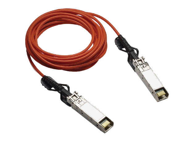
25G SFP28 fiber cable |
SFP-25G-D-AOC-3M |
3 m (9.84 ft) |
|
SFP-25G-D-AOC-5M |
5 m (16.40 ft) |
||
|
SFP-25G-D-AOC-7M |
7 m (22.97 ft) |
||
|
SFP-25G-D-AOC-10M |
10 m (32.81 ft) |
||
|
SFP-25G-D-AOC-20M |
20 m (65.62 ft) |
||
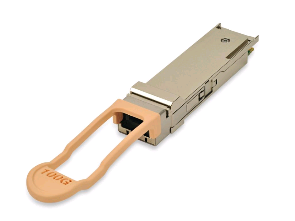
100G QSFP28 transceiver modules and cables
Table 13 QSFP28 transceiver modules
|
Transceiver module model |
Central wavelength (nm) |
Connector |
Fiber diameter and type |
Modal bandwidth (MHz*km) |
Transmission distance |
|
|
|
QSFP-100G-SR4-MM850 |
850 |
MPO (PC-polished) |
50/125 µm MMF |
2000 |
70 m (229.66 ft) |
|
4700 |
100 m (328.08 ft) |
|||||
|
QSFP-100G-SR4-MM850-A |
850 |
MPO (PC-polished) |
50/125 µm MMF |
2000 |
70 m (229.66 ft) |
|
|
4700 |
100 m (328.08 ft) |
|||||
|
QSFP-100G-eSR4-MM850 |
850 |
MPO (PC-polished) |
50/125 µm MMF |
4700 |
300 m (984.25 ft) |
|
|
QSFP-100G-PSM4-SM1310 |
1295 to 1325 |
MPO (APC-polished) |
9/125 µm SMF |
N/A |
500 m (1640.42 ft) |
|
|
|
QSFP-100G-SWDM4-MM850 |
Four lanes: · 850 · 880 · 910 · 940 |
LC |
50/125 µm MMF |
2000 |
75 m (246.06 ft) |
|
4700 |
100 m (328.08 ft) |
|||||
|
QSFP-100G-CWDM4-SM1300-A |
Four lanes: · 1271 · 1291 · 1311 · 1331 |
LC |
9/125 µm SMF |
N/A |
2 km (1.24 miles) |
|
|
QSFP-100G-LR4L-WDM1300 |
Four lanes: · 1264.5 to 1277.5 · 1284.5 to 1297.5 · 1304.5 to 1317.5 · 1324.5 to 1337.5 |
LC |
9/125 µm SMF |
N/A |
2 km (1.24 miles) |
|
|
QSFP-100G-LR4-WDM1300 |
Four lanes: · 1295 · 1300 · 1304 · 1309 |
LC |
9/125 µm SMF |
N/A |
10 km (6.21 miles) |
|
|
QSFP-100G-ER4L-WDM1300 |
Four lanes: · 1294.53 to 1296.59 · 1299.02 to 1301.09 · 1303.54 to 1305.63 · 1308.09 to 1310.19 |
LC |
9/125 µm SMF |
N/A |
40 km (24.86 miles) |
|
|
|
NOTE: MPO connectors include physical contact (PC) connectors with a flat-polished face and angle-polished contact (APC) connectors with an angle-polished face (8°). |
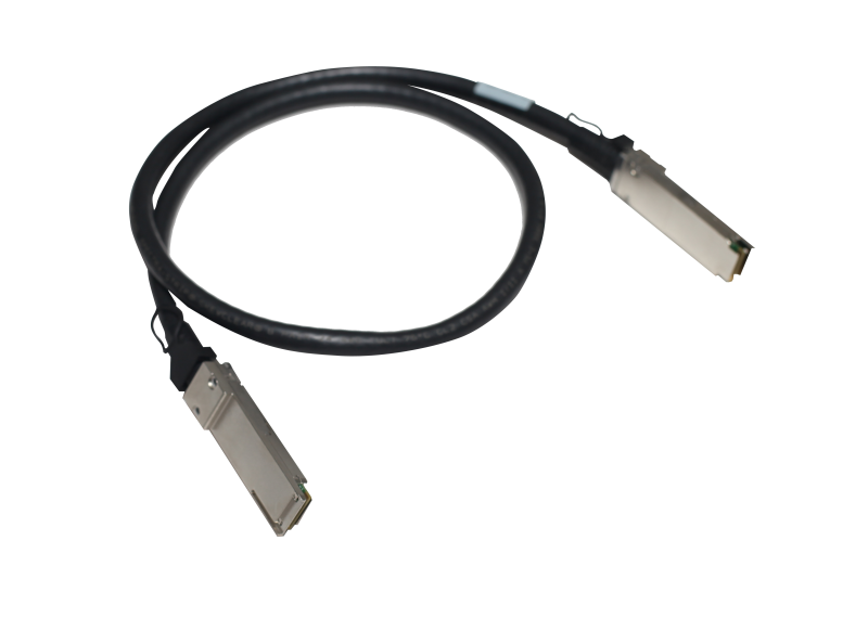
Table 14 QSFP28 cables
|
Cable type |
Cable model |
Cable length |
|
|
|
100G QSFP28 copper cable |
QSFP-100G-D-CAB-1M |
1 m (3.28 ft) |
|
QSFP-100G-D-CAB-3M |
3 m (9.84 ft) |
||
|
QSFP-100G-D-CAB-5M |
5 m (16.40 ft) |
||
|
|
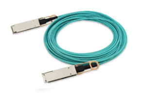
100G QSFP28 fiber cable |
QSFP-100G-D-AOC-7M |
7 m (22.97 ft) |
|
QSFP-100G-D-AOC-10M |
10 m (32.81 ft) |
||
|
QSFP-100G-D-AOC-20M |
20 m (65.62 ft) |
||
|
|
100G QSFP28 to 4×25G SFP28 copper cable |
QSFP-100G-4SFP-25G-CAB-1M |
1 m (3.28 ft) |
|
QSFP-100G-4SFP-25G-CAB-3M |
3 m (9.84 ft) |
||
|
QSFP-100G-4SFP-25G-CAB-5M |
5 m (16.40 ft) |
||
Application scenarios
Wi-Fi 6 connectivity
Figure 16 25GE/100GE campus network solution for Wi-Fi 6 connectivity
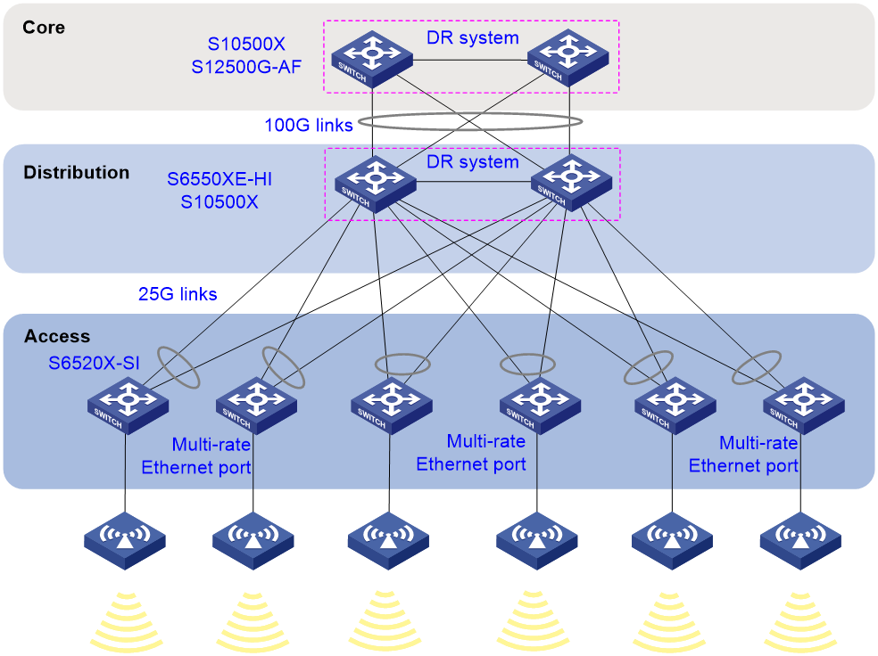
Figure 16 shows the H3C 25GE/100GE campus network solution for Wi-Fi 6 connectivity. In this scenario, each Wi-Fi 6 AP connects to a multi-rate Ethernet port (5G/2.5G/1000/100BASE-T autosensing Ethernet port) on an S6520X-SI switch at the access layer. Each access layer switch is dual-uplinked to the S6550XE-HI/S10500X switches at the distribution layer from a 25G interface module. The distribution layer switches are dual-uplinked to the S10500X/S12500G-AF switches at the core layer from 100G ports.
Medium and large enterprises or campus networks
Figure 17 25G Ethernet solution for medium and large enterprises or campus networks
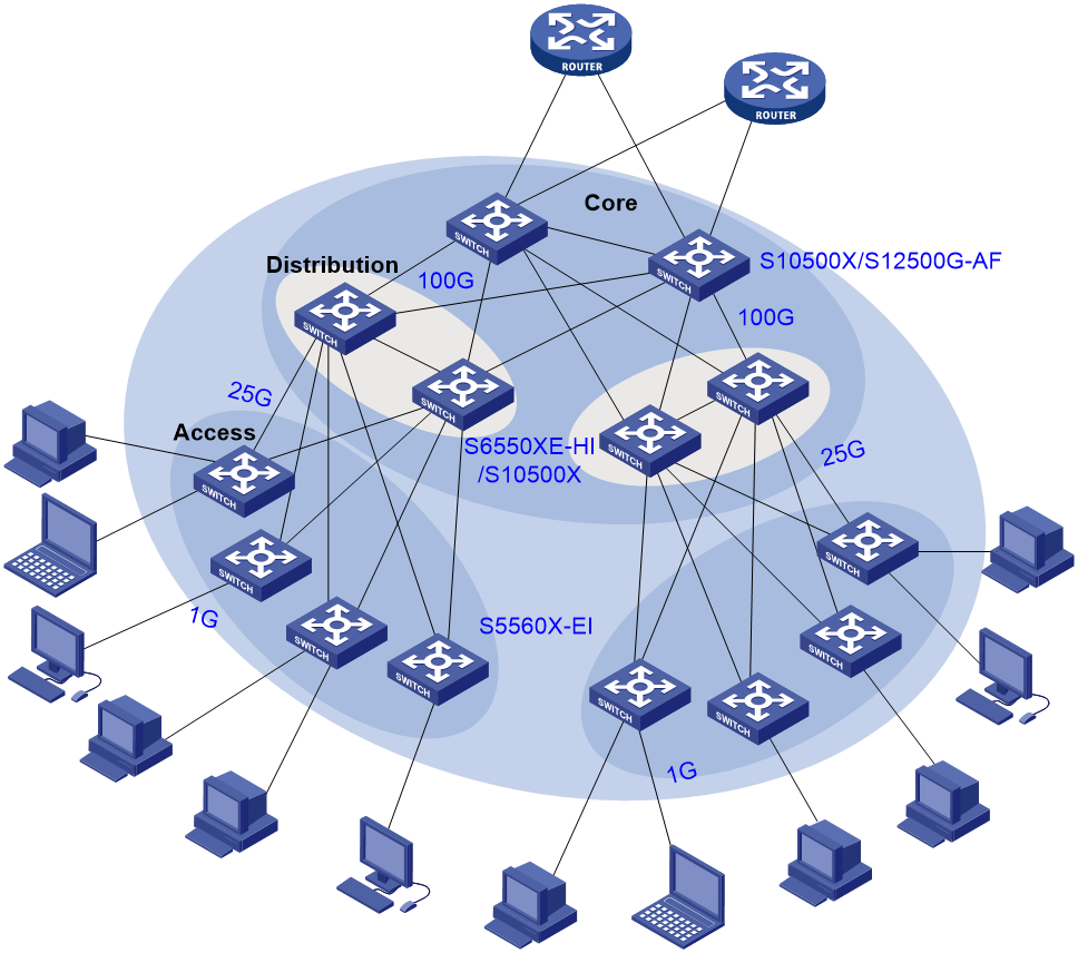
As shown in Figure 17, on large and medium-sized enterprise networks or campus networks, the S6550XE-HI and S10500X Ethernet switches are deployed at the distribution layer to offer high-performance, large-capacity data switching and 100G uplink connectivity. The S5560X-EI switches are deployed at the access layer to provide 1G access and 25G uplink connectivity by using 25G interface modules.
IP central/sub-control network at a radio and television broadcast station
Figure 18 Unified control solution with the spine-leaf architecture
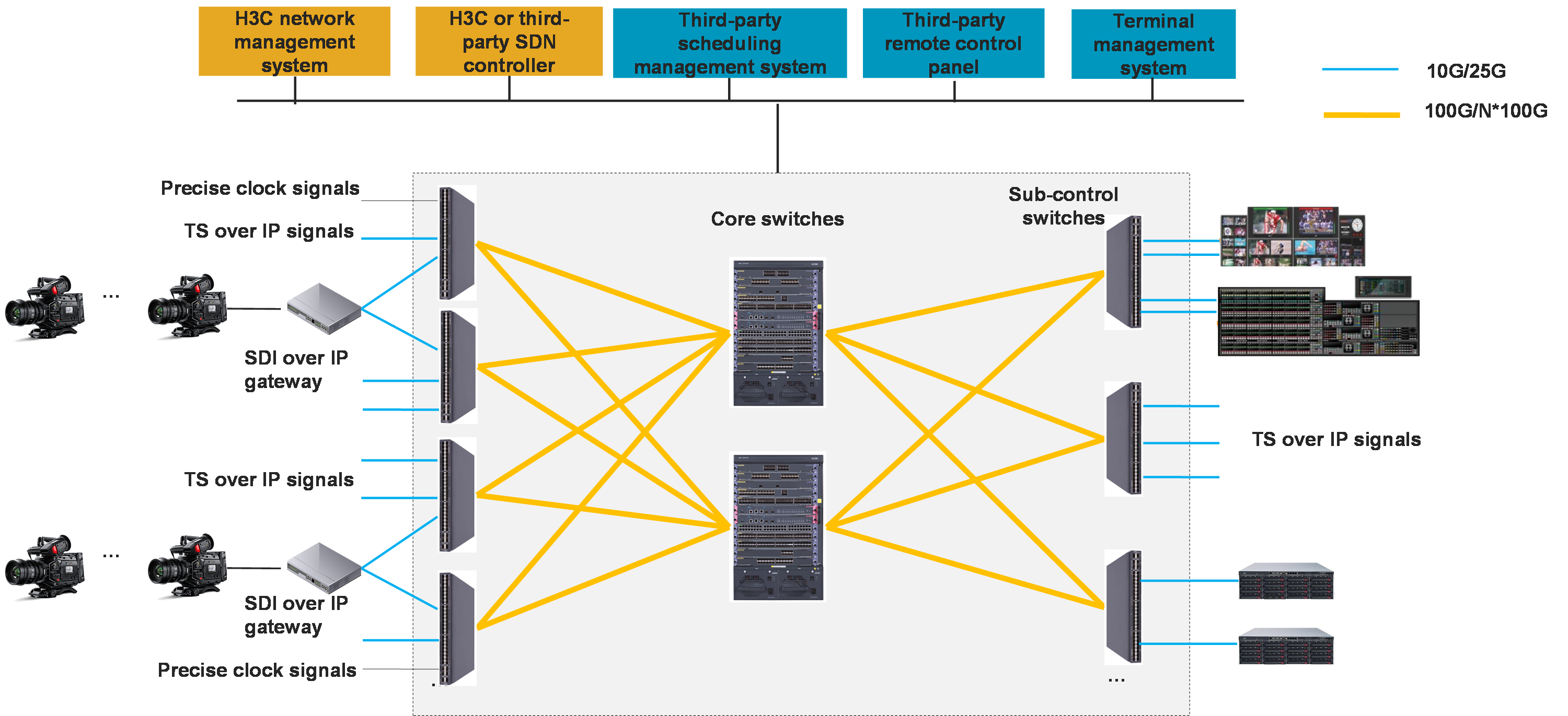
As shown in Figure 18, the IP central/sub-control network at the radio and television station uses the spine-leaf architecture. The central control system is the spine node, and the sub-control systems are leaf nodes. Each node supports active/standby configuration of devices. The S10500X/S12500G-AF switches are deployed as the core switches of the central control system, responsible for receiving, distributing, scheduling, and transmitting signals coming in and out of the station, and enabling overall synchronization of the station. The S6550XE-HI/S10500X switches are used as sub-control system switches in each production and broadcast unit. They interconnect with the central control system, and send data to the core switch of the central control system for processing.
Appendix Acronyms
Table 15 Acronyms
|
Acronyms |
Full name in English |
|
FEC |
Forward error correction |
|
IEEE |
Institute of Electrical and Electronics Engineers |
|
Serdes |
Serializer/Deserializer |
|
SFP28 |
Small form-factor pluggable 28 Gbps |
|
QSFP28 |
Quad small form-factor pluggable 28 Gbps |
|
WAD |
Wavelength-division multiplexing |
|
SMF |
Signal-mode fiber |
|
MMF |
Multi-mode fiber |
|
NRZ |
Non-return-to-zero |
|
PAM4 |
4-level pulse amplitude modulation |
|
CDR |
Clock and data recovery |
