- Released At: 08-01-2024
- Page Views:
- Downloads:
- Table of Contents
- Related Documents
-
|
|
|
|
|
EVPN VXLAN Technology White Paper |
|
|
|
|
Copyright © 2020 New H3C Technologies Co., Ltd. All rights reserved.
No part of this manual may be reproduced or transmitted in any form or by any means without prior written consent of New H3C Technologies Co., Ltd.
Except for the trademarks of New H3C Technologies Co., Ltd., any trademarks that may be mentioned in this document are the property of their respective owners.
This document provides generic technical information, some of which might not be applicable to your products.
The information in this document is subject to change without notice.
EVPN VXLAN working mechanism in the control plane
BGP EVPN neighbor establishment
VXLAN tunnel and BUM table creation
MAC/IP route advertisement and learning
External route advertisement and learning
EVPN VXLAN Layer 2 forwarding in the data plane
EVPN gateway forwarding in the data plane
Centralized EVPN gateway traffic forwarding
Distributed EVPN gateway symmetric IRB forwarding
Multicast in single-homed sites
Distributed EVPN gateway deployment
EVPN VXLAN deployment through an SDN controller
Overview
Technical background
The widespread adoption of data center services and the unceasing increase of customer demands make data centers larger and more complex. It is more difficult for the network administrators to expand and manage the data centers. In addition, the enterprises might deploy data centers at geographically dispersed sites in consideration of disaster recovery, branch deployment, and full utilization of resources. Thus, data center interconnect becomes a major issue for the enterprises together with reducing management costs and flexibly expanding data centers.
Ethernet Virtual Private Network (EVPN) is a Layer 2 network interconnection technology based on the overlay technology. EVPN provides benefits including high scalability and easy deployment. This technology extends MP-BGP to advertise MAC and IP reachability information and multicast information among sites. Based on the advertised information, EVPN generates MAC address entries and routing table entries to guide Layer 2 and Layer 3 packet forwarding across sites. The EVPN technology excellently meets the requirements of large data center networks.
At present, EVPN has been widely used in data centers. It also has been applied to the campus access network and the WAN network.
Benefits
EVPN defines a set of control plane standards. The encapsulation technology used in the data plane is customizable. The EVPN framework is as shown in Figure 1. At present, Comware supports the VXLAN and MPLS technologies on the data plane for EVPN. This technology white paper describes only EVPN with the VXLAN data plane (also known as EVPN VXLAN).
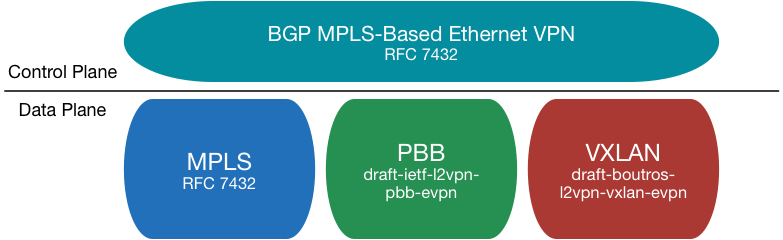
EVPN VXLAN provides the following benefits:
· Configuration automation—MP-BGP automates VTEP discovery, VXLAN tunnel establishment, and VXLAN tunnel assignment to ease deployment.
· Separation of the control plane and the data plane—EVPN VXLAN uses MP-BGP to advertise routes in the control plane and uses VXLAN to forward traffic in the data plane.
· Multihoming—EVPN VXLAN supports deploying multiple VTEPs at a site for redundancy and load sharing.
· Integrated routing and bridging (IRB)—MP-BGP advertises both Layer 2 and Layer 3 host reachability information to provide optimal forwarding paths and minimize flooding.
· Multicast—EVPN VXLAN uses BGP EVPN routes to advertise and withdraw multicast entries among VTEPs. Multicast forwarding is supported in both single-homed and multihomed sites.
EVPN VXLAN implementation
EVPN VXLAN network model
As shown in Figure 2, EVPN VXLAN uses the VXLAN technology for traffic forwarding in the data plane. A typical EVPN VXLAN network has the following device roles:
· User terminal—Supported user terminals include PCs, wireless terminals, and VMs on servers. User terminals in different sites have Layer 2 connectivity if they are in the same VXLAN. User terminals in different VXLANs are isolated at Layer 2.
|
|
NOTE: This document uses VMs as examples to describe the mechanisms of EVPN VXLAN. The mechanisms do not differ between different kinds of user terminals. |
· VXLAN tunnel endpoint (VTEP)—The transport edge devices configured with EVPN VXLAN settings are VTEPs. All VXLAN processing is performed on VTEPs. The ingress VTEP encapsulates VXLAN traffic in the VXLAN, outer UDP, and outer IP headers, and forwards the traffic through VXLAN tunnels. The egress VTEP removes the VXLAN encapsulation and forwards the traffic to the destination.
|
|
NOTE: VTEPs include Layer 2 VTEPs and EVPN gateways. A Layer 2 VTEP provides Layer 2 forwarding for terminals in the same VXLAN. An EVPN gateway provides Layer 3 forwarding for terminals in different VXLANs or for terminals in VXLANs to communicate with the external network. For more information about EVPN gateways, see "EVPN gateway forwarding in the data plane." |
· Transport network device—Devices in the transport network (for example, the P device in Figure 2) forward VXLAN traffic only based on the outer IP header of VXLAN packets.
Figure 2 EVPN VXLAN network model
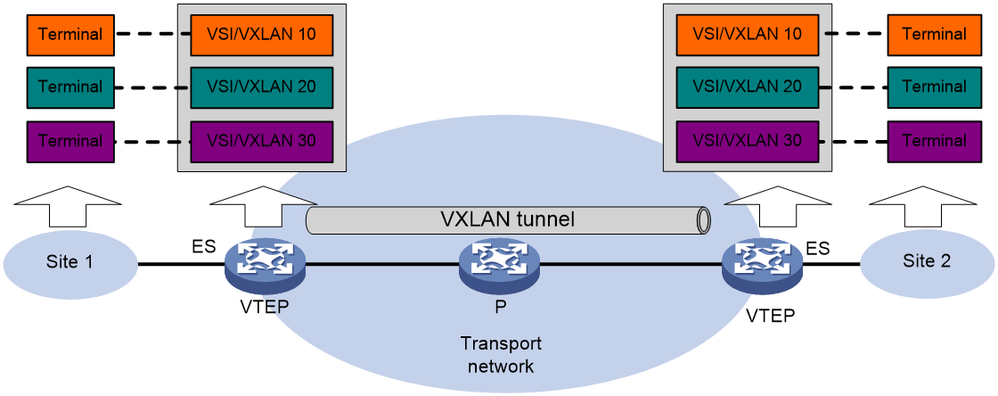
A VTEP uses ESs, VSIs, EVPN instances, and VXLAN tunnels to provide VXLAN services:
· Ethernet segment (ES)—An ES is a link that connects a site to a VTEP. Each ES is uniquely identified by an Ethernet segment identifier (ESI). For high availability or load sharing, connect a site to multiple VTEPs. The links connected to the VTEPs form one ES.
· VSI—A virtual switch instance is a virtual Layer 2 switched domain. Each VSI provides switching services only for one VXLAN. VSIs learn MAC addresses and forward frames independently of one another.
· VXLAN/EVPN instance—User terminals in different sites have Layer 2 connectivity if they are in the same VXLAN. A VXLAN is created on a VSI. Each VXLAN is identified by a 24-bit VXLAN ID which is also called the virtual network identifier (VNI). An EVPN instance is associated with a VXLAN on a VSI.
· VXLAN tunnel—Logical point-to-point tunnels between VTEPs over the transport network. Each VXLAN tunnel can trunk multiple VXLANs.
Layered transport network
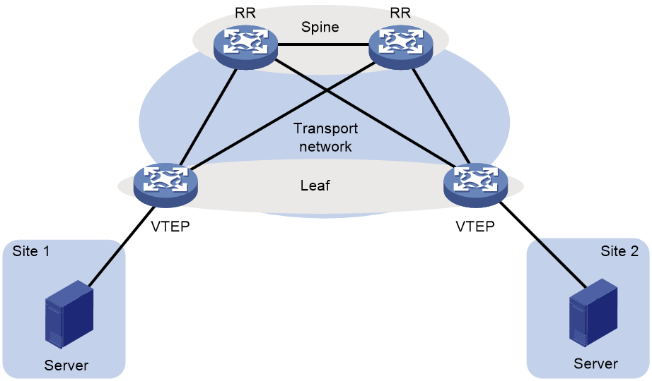
As shown in Figure 3, typically the EVPN VXLAN transport network uses a layered structure. On the transport network, leaf nodes act as VTEPs to provide VXLAN services, and spine nodes perform forwarding for VXLAN traffic based on the outer IP header. If all VTEPs and transport network devices of an EVPN VXLAN network belong to the same AS, you can configure the spine nodes as route reflectors (RRs) to reflect routes between the VTEPs. In the centralized EVPN gateway deployment, the VTEPs are Layer 2 VTEPs and an RR acts as the centralized EVPN gateway at the same time. In the distributed EVPN gateway deployment, the VTEPs act as distributed EVPN gateways and the RRs only reflect BGP EVPN routes between the VTEPs. RRs in the distributed EVPN gateway deployment do not perform VXLAN encapsulation and de-encapsulation.
Figure 3 Layered transport network
EVPN VXLAN working mechanism in the control plane
EVPN VXLAN uses MP-BGP to advertise MAC and IP reachability information among VTEPs in the control plane. The MAC and IP learning control is similar to MPLS L3VPN, which provides enhanced ability in controlling the MAC and IP learning. The control plane-based address learning also has the following benefits:
· Good scalability.
· Better isolation for hosts or VMs.
· Solves the issue of traffic load sharing in a multihoming network and reduces the time for network convergence.
BGP EVPN neighbor establishment
BGP adds the EVPN subsequent address family under the L2VPN address family for EVPN neighbor negotiation and establishment. The EVPN address family is identified by AFI 25 and SAFI 70.
In an EVPN VXLAN network, the VTEPs can establish IBGP neighbor relationships or EBGP neighbor relationships.
· To establish IBGP neighbor relationships, you need to deploy RRs to simplify the network connections. All VTEPs in the EVPN VXLAN network establish BGP neighbor relationships only with the RRs. Each RR maintains a VTEP list and reflects all BGP EVPN routes received from a VTEP to the other VTEPs. The RRs can be deployed on spine nodes, leaf nodes, or independent devices.
· To establish EBGP neighbor relationships, no RR is required. BGP automatically advertises the BGP EVPN routes received from an EBGP neighbor to the other EBGP neighbors and to all IBGP neighbors.
BGP EVPN routes
To support EVPN VXLAN, MP-BGP introduces the following network layer reachability information (BGP EVPN routes):
· Ethernet auto-discovery route (RT-1)—Advertises ES information in multihomed sites, which facilitates split horizon, aliasing, DF/BDF backup and switchover.
· MAC/IP advertisement route (RT-2)—Advertises MAC reachability information and host route information (host ARP or ND information).
· Inclusive multicast Ethernet tag (IMET) route (RT-3)—Advertises VTEP and VXLAN mappings for automating VTEP discovery, VXLAN tunnel establishment, and VXLAN tunnel assignment.
· Ethernet segment route (RT-4)—Advertises ES and VTEP mappings for discovering other VTEPs connected to the same ES and electing the DF.
· IP prefix advertisement route (RT-5)—Advertises external routes as IP prefixes.
· Selective multicast Ethernet tag (SMET) route (RT-6)—Advertises IGMP multicast group information among VTEPs in an EVPN VXLAN network. A VTEP advertises an SMET route only when receiving a membership report for an IGMP multicast group for the first time. The VTEP does not advertise an SMET route if subsequent membership reports for the multicast group use the same IGMP version as the first membership report.
· IGMP join synch route (RT-7)—Advertises IGMP membership reports among redundant VTEPs for an ES.
· IGMP leave synch route (RT-8)—Advertises IGMP leave group messages for withdrawal of IGMP join synch routes among redundant VTEPs for an ES.
MP-BGP uses the route distinguisher (RD) field to differentiate BGP EVPN routes of different VXLANs and uses route targets to control the advertisement and acceptance of BGP EVPN routes. MP-BGP supports the following types of route targets:
· Export target—A VTEP sets the export targets for BGP EVPN routes learned from the local site before advertising them to remote VTEPs.
· Import target—A VTEP checks the export targets of BGP EVPN routes received from remote VTEPs. The VTEP imports the BGP EVPN routes if a same value exists between the export targets and the local import targets.
VXLAN tunnel and BUM table creation
VXLAN uses the MAC-in-UDP encapsulation to build an overlay network on top of an existing physical IP network. In the IP network, VXLAN uses ingress replication (also known as head-end replication) to forward broadcast, unknown unicast, and unknown multicast (BUM) traffic. Each VXLAN's VSI maintains a BUM table. The BUM table contains the VXLAN tunnels that a VTEP uses to forward BUM traffic to remote VTEPs.
EVPN VXLAN uses the following methods to create VXLAN tunnels and the BUM table:
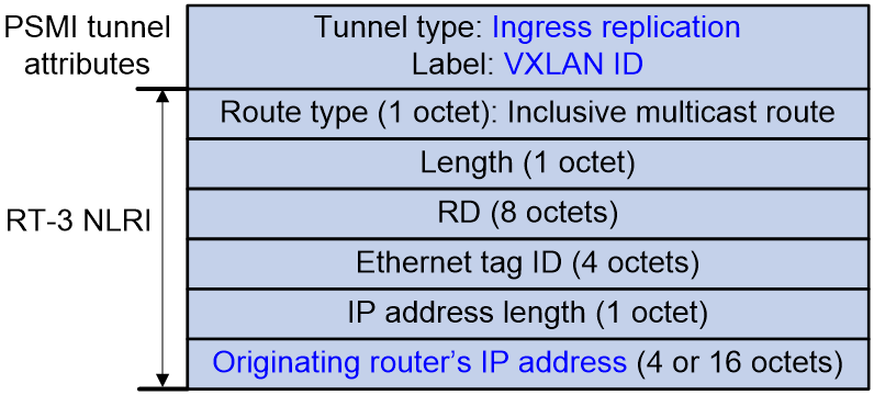
· For Layer 2 forwarding, EVPN VXLAN uses IMET routes (RT-3) to automatically discover VTEPs, establish VXLAN tunnels, and create the BUM table.
Figure 4 shows the message format of an RT-3 route. VTEPs advertise the VXLAN IDs and IP addresses they have through IMET routes. If two VTEPs have the same VXLAN ID, they automatically establish a VXLAN tunnel and assign the tunnel to the VXLAN. For each VXLAN, the assigned VXLAN tunnels form the BUM table.
Figure 4 RT-3 route message format
· For Layer 3 forwarding on distributed EVPN gateways, EVPN VXLAN uses MAC/IP advertisement routes (RT-2) or IP prefix advertisement routes (RT-5) to automatically discover VTEPs and establish VXLAN tunnels.
In the distributed EVPN gateway deployment, VTEPs advertise RT-2 routes or RT-5 routes with the export targets. When a VTEP receives a RT-2 or RT-5 route, it compares the export targets of the route with the local import targets. If a same value exists between the export and import route targets, the VTEP establishes a VXLAN tunnel with the remote VTEP. In addition, the VTEP associates the tunnel with the L3 VXLAN ID of the VPN instance that is associated with the local EVPN gateway. For more information about the distributed EVPN gateway deployment, see "Distributed EVPN gateway symmetric IRB forwarding."
If the above methods discover the same remote VTEP for a VTEP, the VTEPs establish only one VXLAN tunnel between them. The tunnel is associated with multiple VXLANs for both Layer 2 forwarding and Layer 3 forwarding. Only one VXLAN tunnel can be established between two VTEPs.
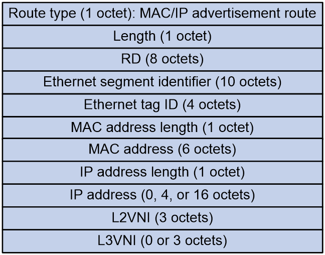
MAC/IP route advertisement and learning
EVPN VXLAN uses MAC/IP advertisement routes (RT-2) to advertise MAC reachability information and the host route information (ARP information and ND information). In an EVPN VXLAN network, ARP or ND request flooding is not necessary.
Figure 5 shows the message format of an RT-2 route
Figure 5 RT-2 route message format
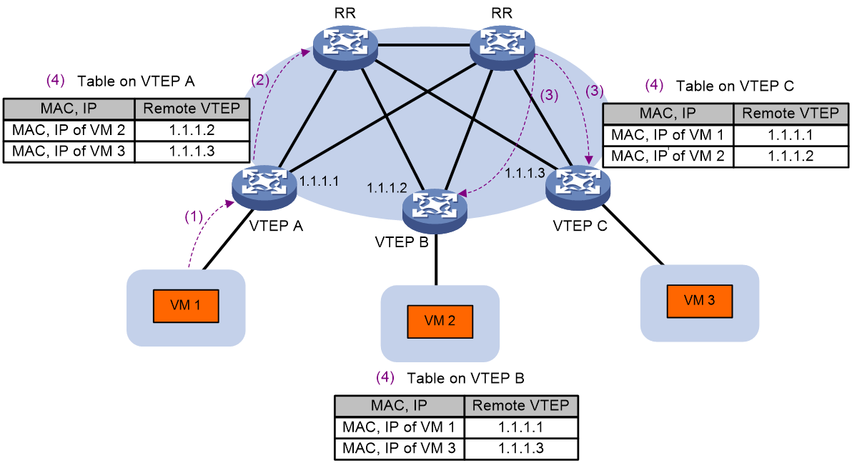
As shown in Figure 6, the MAC address and ARP/ND information is advertised and learned as follows:
1. A VTEP learns local MAC and ARP/ND information through the data plane. Local MAC addresses are learned from the source MAC addresses of Ethernet frames. ARP/ND information is obtained from ARP/ND protocol packets such as ARP, gratuitous ARP, and ND packets.
2. The VTEP advertises the local MAC and ARP/ND information to the RRs through BGP EVPN RT-2 routes in the control plane.
3. The RRs reflect the received RT-2 routes to all BGP EVPN neighbors (the remote VTEPs).
4. After receiving the RT-2 routes, the remote VTEPs add the MAC addresses in the routes to the MAC address table and add the ARP/ND information to the ARP/ND table and the routing table.
Figure 6 MAC/IP route advertisement and learning process
To suppress ARP requests, the VTEPs need to carry IP information when they advertise RT-2 routes. After learning the remote host ARP information from the RT-2 routes, a VTEP can reply to ARP requests initiated by hosts without flooding the requests to remote sites. If the network does not have Layer 3 forwarding, RT-2 routes do not need to have IP information.
For Layer 3 forwarding, the VTEPs can obtain remote MAC addresses from ARP information. As a best practice to reduce advertised BGP EVPN routes, you can disable the Comware device from advertising RT-2 routes that contain only MAC address information.
In the centralized EVPN gateway deployment, the Layer 2 VTEPs need to advertise ARP information to the gateway. The gateway adds the ARP entries and generates 32-bit host routes for the ARP entries. The next hop of a host route is the destination address of the route.
In the distributed EVPN gateway deployment, each distributed EVPN gateway advertises learned ARP information to the other distributed EVPN gateways through RT-2 routes. A distributed EVPN gateway issues the IP addresses of RT-2 routes to the routing table of the corresponding VPN instance to generate 32-bit host routes. The next hop of a 32-bit host route is the distributed EVPN gateway that advertises the RT-2 route of the host.
External route advertisement and learning
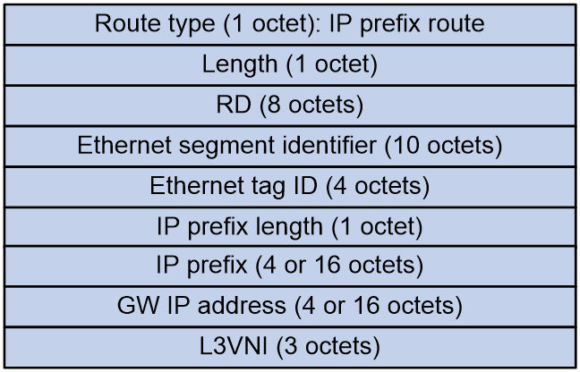
You can deploy one or more border gateways for the EVPN VXLAN network to communication with the Layer 3 external network and to import external routes. The border gateways are also called border leaves in this document. A border leaf runs common routing protocols on the interfaces at the external network side to learn external routes. Then, the border leaf imports the external routes to BGP EVPN as IP prefix advertisement routes (RT-5) and advertises the RT-5 routes to the VTEPs in the EVPN VXLAN network. The next hop of these RT-5 routes is the border leaf that advertises the routes. If you deploy multiple border leaves, all the border leaves can advertise external routes as RT-5 routes. The routes are equal cost for traffic load sharing.
Figure 7 shows the message format of an RT-5 route.
Figure 7 RT-5 route message format
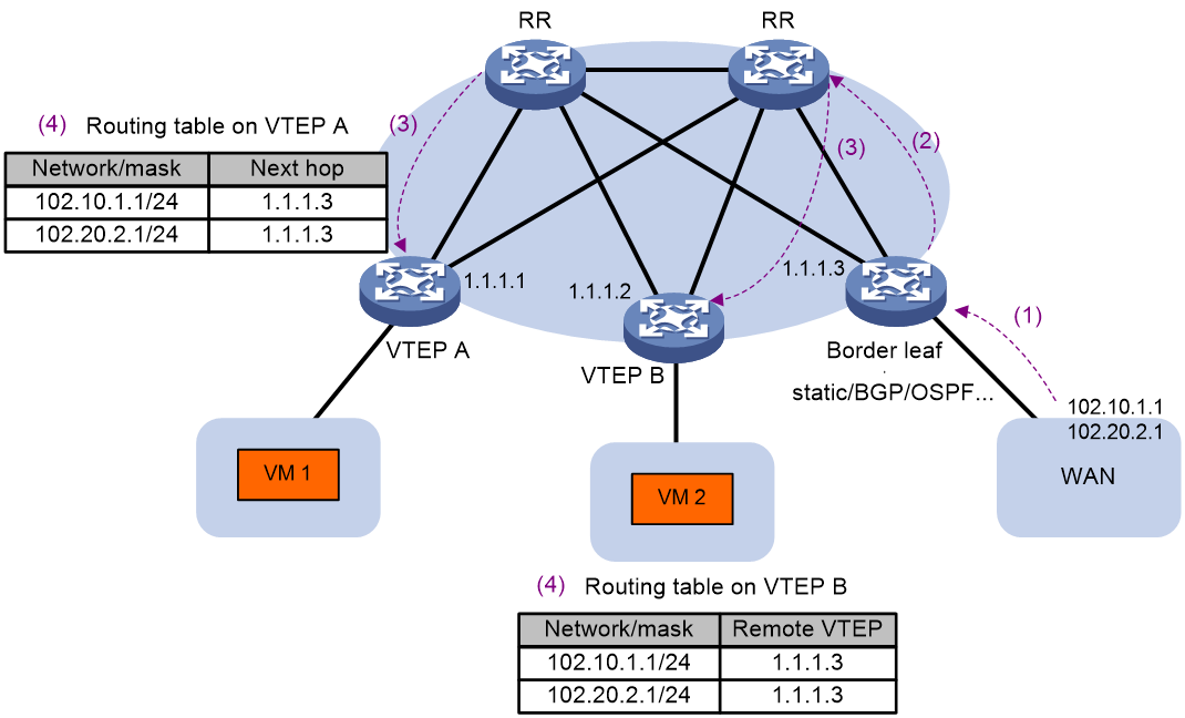
As shown in Figure 8, the external routes are advertised and learned as follows:
1. For the border leaf to learn external routes, configure static routes on the border leaf and the WAN network or run dynamic routing protocols such as BGP and OSPF.
2. On the border leaf, import external routes to BGP EVPN as RT-5 routes. The RT-5 routes are advertised to the RR.
3. The RR reflects the RT-5 routes received from the border leaf to the VTEPs.
4. Upon receiving an RT-5 route, a VTEP compares the export targets of the route with the local import targets. If the route targets match, the VTEP adds the route to the routing table of the corresponding VPN instance.
Figure 8 External route advertisement and learning
MAC mobility
MAC mobility refers to that a VM or host moves from one VTEP to another VTEP. EVPN VXLAN uses the MAC Mobility extended community attribute to ensure that VTEPs can update MAC/IP advertisement routes in time after a MAC move event.
1. A VTEP advertises a MAC/IP advertisement route for a VM or host for the first time. The route does not contain the MAC Mobility extended community attribute.
2. The VM or host migrates from the VTEP to another VTEP. The destination VTEP senses the VM or host and advertises a MAC/IP advertisement route for the VM or host. The route carries the MAC Mobility extended community attribute. The attribute has a sequence number that increases when the MAC address moves. The sequence number identifies the most recent move if the MAC address moves multiple times.
3. The remote VTEPs receive the MAC/IP advertisement route advertised by the migration destination VTEP. They update the MAC/IP advertisement route locally and change the route next hop to the migration destination VTEP.
4. The migration source VTEP withdraws the old route for the MAC address after receiving the new route.
ARP flood suppression
ARP flood suppression reduces ARP request broadcasts by enabling the VTEP to reply to ARP requests on behalf of VMs.
As shown in Figure 9, this feature snoops ARP requests, ARP responses, and BGP EVPN RT-2 routes to populate the ARP flood suppression table with local and remote MAC addresses. If an ARP request has a matching entry, the VTEP replies to the request on behalf of the VM. If no match is found, the VTEP floods the request to both local and remote sites.
Figure 9 ARP flood suppression
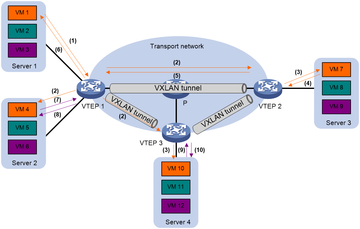
ARP flood suppression uses the following workflow:
1. VM 1 sends an ARP request to obtain the MAC address of VM 7.
2. VTEP 1 creates a suppression entry for VM 1, floods the ARP request in the VXLAN, and sends the suppression entry to VTEP 2 and VTEP 3 through BGP EVPN.
3. VTEP 2 and VTEP 3 de-encapsulate the ARP request and broadcast the request in the local sites.
4. VM 7 sends an ARP reply.
5. VTEP 2 creates a suppression entry for VM 7, forwards the ARP reply to VTEP 1, and sends the suppression entry to VTEP 1 and VTEP 3 through BGP EVPN.
6. VTEP 1 de-encapsulates the ARP reply and forwards the ARP reply to VM 1.
7. VM 4 sends an ARP request to obtain the MAC address of VM 1.
8. VTEP 1 creates a suppression entry for VM 4 and replies to the ARP request.
9. VM 10 sends an ARP request to obtain the MAC address of VM 1.
10. VTEP 3 creates a suppression entry for VM 10 and replies to the ARP request.
EVPN VXLAN Layer 2 forwarding in the data plane
Unicast traffic forwarding
A VTEP performs typical Layer 2 forwarding for known unicast traffic within the local site.
The following process applies to the forwarding of a known unicast frame between sites:
1. Upon receiving the frame, the source VTEP identifies the VSI of the frame and looks up the VSI's MAC address table to find that the outgoing interface is a VXLAN tunnel interface.
2. The source VTEP encapsulates the Ethernet frame in the VXLAN/UDP/IP header.
In the outer IP header, the source IP address is the source VTEP's VXLAN tunnel source IP address. The destination IP address is the VXLAN tunnel destination IP address.
3. The source VTEP forwards the encapsulated packet out of the outgoing VXLAN tunnel interface found in the VSI's MAC address table.
4. The intermediate transport devices forward the packet to the destination VTEP by using the outer IP header.
5. The destination VTEP removes the headers on top of the inner Ethernet frame. It then performs MAC address table lookup in the VXLAN's VSI to forward the frame out of the matching outgoing interface.
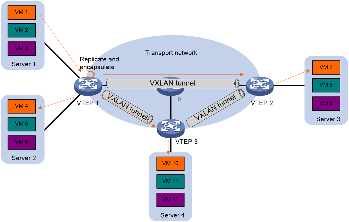
BUM traffic forwarding
A VTEP floods BUM traffic to all site-facing interfaces and VXLAN tunnels in the VXLAN, except for the incoming interface.
EVPN VXLAN supports unicast mode (also called head-end replication) for flooding traffic to VXLAN tunnels. As shown in Figure 10, the source VTEP adds the VXLAN encapsulation to the flood frame, replicates the flood frame, and then sends one replica to the destination IP address of each VXLAN tunnel in the VXLAN. The BUM table for traffic flooding is automatically created. You do not need to manually create the BUM table.
EVPN gateway forwarding in the data plane
EVPN VXLAN provides the following EVPN gateway placement designs:
· Centralized EVPN gateway deployment—Uses one VTEP to provide Layer 3 forwarding for VXLANs. Typically, the gateway-collocated VTEP connects to other VTEPs and the external network. To use this design, make sure the gateway has sufficient bandwidth and processing capability.
· Distributed EVPN gateway deployment—Deploys one EVPN gateway on each VTEP to provide Layer 3 forwarding for VXLANs at their respective sites. This design distributes the Layer 3 traffic load across VTEPs. However, its configuration is more complex than the centralized EVPN gateway design.
Centralized EVPN gateway traffic forwarding
In the centralized EVPN gateway deployment, a Layer 2 VTEP advertises the ARP information of local VMs to the centralized EVPN gateway through BGP EVPN routes. The gateway creates an ARP entry for each VM. In addition, the gateway generates 32-bit host routes for the VMs based on the ARP information. The next hop of such a host route is the destination address of that route (the IP address of the corresponding VM).
The following shows how a centralized EVPN gateway forwards traffic:
· For a packet destined for a VM in a site from the external network, the gateway performs the following operations:
a. Searches the routing table for the destination. The gateway finds a 32-bit host route of which the next hop is the IP address of the VM.
b. Searches the ARP entries for the next hop of the route and replaces the destination MAC address of the packet with the MAC address of the VM.
c. Adds the VXLAN encapsulation to the packet and forwards the encapsulated packet to the destination Layer 2 VTEP. The destination VTEP de-encapsulates the VXLAN packet and forwards the inner frame to the destination VM based on the destination MAC address.
· For a packet destined for the external network from a VM, the forwarding process is as follows:
a. The source VM sends the packet to the local VTEP. The destination MAC address is the MAC address of the gateway.
b. The VTEP searches the MAC address table for the outgoing interface destined for the gateway. It adds the VXLAN encapsulation to the packet and forwards the VXLAN packet to the gateway.
c. The gateway de-encapsulates the VXLAN packet and performs typical Layer 3 forwarding to send the packet to the destination IP address. In this scenario, the centralized EVPN gateway is an IP gateway.
· For a packet from a VM to another VM in the EVPN VXLAN network, the following process applies:
¡ If the VMs belong to the same VXLAN, the VTEPs search the VXLAN VSI's MAC address table for the outgoing interface to reach the destination. The forwarding process involves only Layer 2 forwarding.
¡ If the VMs belong to different VXLANs, the source VM must deliver the packet to the local VTEP with the destination MAC address as that of the gateway. The gateway performs Layer 3 forwarding to deliver the packet to the destination VXLAN. In this scenario, the centralized EVPN gateway is a VXLAN gateway.
Distributed EVPN gateway symmetric IRB forwarding
A distributed EVPN gateway forwards Layer 3 traffic based on FIB entries generated from BGP EVPN routes and ARP/ND information.
On the distributed EVPN gateway deployment, you need to configure a VXLAN on each distributed EVPN gateway for the attached user terminals. A distributed EVPN gateway does not need to maintain the local ARP/ND information for the VXLAN. It needs to maintain the ARP/ND information advertised by remote distributed EVPN gateways.
Symmetric IRB
A distributed EVPN gateway uses symmetric IRB for Layer 3 forwarding, which means both the ingress and egress gateways perform Layer 2 and Layer 3 lookups. Symmetric IRB introduces the following concepts:
· L3 VXLAN ID—Also called L3 VNI. An L3 VXLAN ID identifies the traffic of a routing domain where devices have Layer 3 reachability. An L3 VXLAN ID is associated with one VPN instance. Distributed EVPN gateways use VPN instances to isolate traffic of different services.
· Router MAC address—Each distributed EVPN gateway has a unique router MAC address used for inter-gateway forwarding. The MAC addresses in the inner Ethernet header of VXLAN packets are router MAC addresses of distributed EVPN gateways.
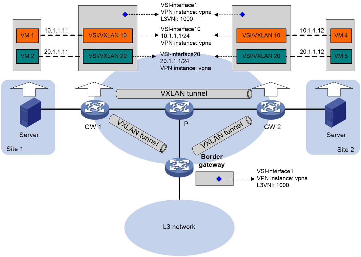
VSI interfaces
As shown in Figure 11, each distributed EVPN gateway has the following types of VSI interfaces:
· VSI interface as a gateway interface of a VXLAN—The VSI interface acts as the gateway interface for VMs in a VXLAN. The VSI interface is associated with a VSI and a VPN instance. On different distributed EVPN gateways, the VSI interface of a VXLAN use the same IP address to provide services.
· VSI interface associated with an L3 VXLAN ID—The VSI interface is associated with a VPN instance and assigned an L3 VXLAN ID. VSI interfaces associated with the same VPN instance share an L3 VXLAN ID.
A border gateway only has VSI interfaces that are associated with an L3 VXLAN ID.
Figure 11 Example of distributed EVPN gateway deployment
Traffic forwarding
This section uses dynamically learned ARP entries to describe the forwarding processes.
A distributed EVPN gateway can work in one of the following modes:
· Switching and routing mode—Forwards Layer 2 traffic based on the MAC address table and forwards Layer 3 traffic based on the FIB table. In this mode, you need to enable ARP flood suppression on the distributed EVPN gateway to reduce flooding.
· Routing mode—Forwards both Layer 2 and Layer 3 traffic based on the FIB table. In this mode, you need to enable local proxy ARP on the distributed EVPN gateway.
For more information about MAC address table-based Layer 2 forwarding, see "Unicast traffic forwarding."
Figure 12 shows the intra-site Layer 3 forwarding process.
1. The source VM sends an ARP request.
¡ If the source and destination VMs are in the same subnet, the source VM requests to obtain the MAC address of the destination VM.
¡ If the source and destination VMs are in different subnets, the source VM requests to obtain the MAC address of the gateway.
2. The gateway identifies the VSI of the ARP request and replies to the source VM with the MAC address of the VSI interface associated with the source VM's VSI.
3. The source VM sends a Layer 3 packet to the gateway.
4. The gateway looks up the FIB table of the VPN instance associated with the source VM's VSI and finds the matching outgoing site-facing interface.
5. The gateway processes the Ethernet header of the Layer 3 packet as follows:
¡ Replaces the destination MAC address with the destination VM's MAC address.
¡ Replaces the source MAC address with the VSI interface's MAC address.
6. The gateway forwards the Layer 3 packet to the destination VM.
Figure 12 Intra-site Layer 3 forwarding
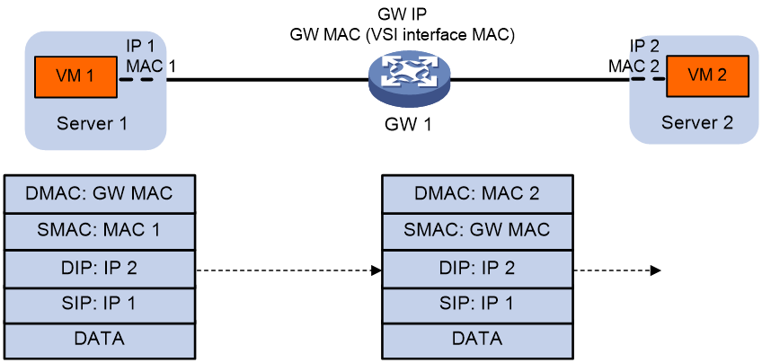
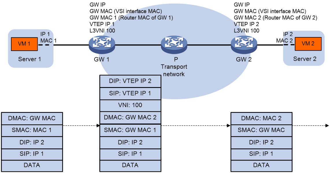
Figure 13 shows the inter-site Layer 3 forwarding process.
1. The source VM sends an ARP request.
¡ If the source and destination VMs are in the same subnet, the source VM requests to obtain the MAC address of the destination VM.
¡ If the source and destination VMs are in different subnets, the source VM requests to obtain the MAC address of the gateway.
2. The gateway identifies the VSI of the ARP request and replies to the source VM with the MAC address of the VSI interface associated with the source VM's VSI.
3. The source VM sends a Layer 3 packet to the gateway.
4. The gateway looks up the FIB table of the VPN instance associated with the source VM's VSI and finds the matching outgoing VSI interface.
5. The gateway processes the Ethernet header of the Layer 3 packet as follows:
¡ Replaces the destination MAC address with the destination gateway's router MAC address.
¡ Replaces the source MAC address with its own router MAC address.
6. The gateway adds VXLAN encapsulation to the Layer 3 packet and forwards the packet to the destination gateway. The encapsulated VXLAN ID is the L3 VXLAN ID of the corresponding VPN instance.
7. The destination gateway identifies the VPN instance of the packet based on the L3 VXLAN ID and removes the VXLAN encapsulation. Then the gateway forwards the packet based on the matching ARP entry in the VPN instance.
Figure 13 Inter-site Layer 3 forwarding
EVPN VXLAN multihoming
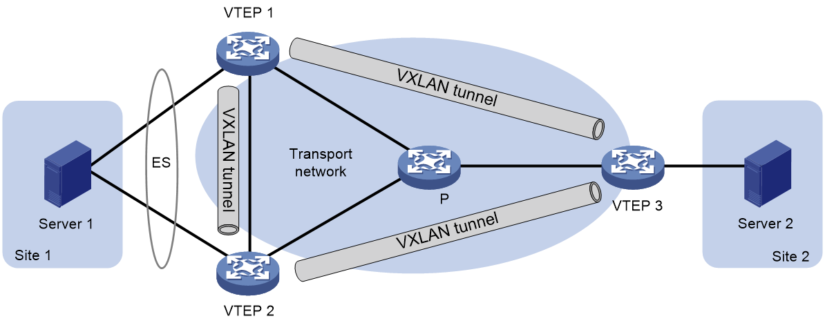
About EVPN VXLAN multihoming
As shown in Figure 14, EVPN VXLAN supports deploying multiple VTEPs at a site for redundancy and high availability. On the redundant VTEPs, Ethernet links connected to the site form an ES that is uniquely identified by an ESI.
Figure 14 EVPN VXLAN multihoming
DF election
To prevent redundant VTEPs from sending duplicate flood traffic to a multihomed site, a designated forwarder (DF) is elected from the VTEPs for each AC to forward flood traffic to the AC. VTEPs that fail the election are assigned the backup designated forwarder (BDF) role. BDFs of an AC do not forward flood traffic to the AC.
Redundant VTEPs at a site send Ethernet segment routes to one another to advertise ES and VTEP IP mappings. A VTEP accepts the Ethernet segment routes only when it is configured with an ESI. Then, the VTEPs select a DF for each AC based on the ES and VTEP IP mappings by using the following procedure:
1. Arrange source IP addresses in Ethernet segment routes with the same ESI in ascending order and assign a sequence number to each IP address, starting from 0.
2. Divide the lowest VLAN ID permitted on an AC by the number of the redundant VTEPs, and match the reminder to the sequence numbers of IP addresses.
3. Assign the DF role to the VTEP that uses the IP address with the matching sequence number.
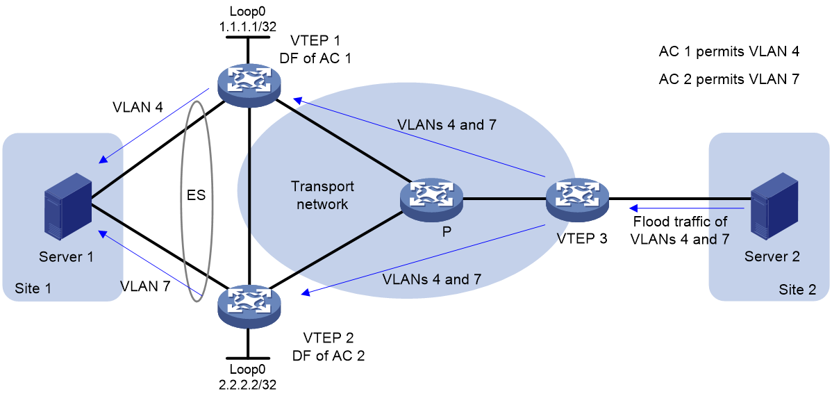
The following uses AC 1 in Figure 15 as an example to explain the DF election procedure:
1. VTEP 1 and VTEP 2 send Ethernet segment routes to each other.
2. Sequence numbers 0 and 1 are assigned to IP addresses 1.1.1.1 and 2.2.2.2 in the Ethernet segment routes, respectively.
3. The VTEPs divide 4 (the lowest VLAN ID permitted by AC 1) by 2 (the number of redundant VTEPs), and match the reminder 0 to the sequence numbers of the IP addresses.
4. The DF role is assigned to VTEP 1 at 1.1.1.1.
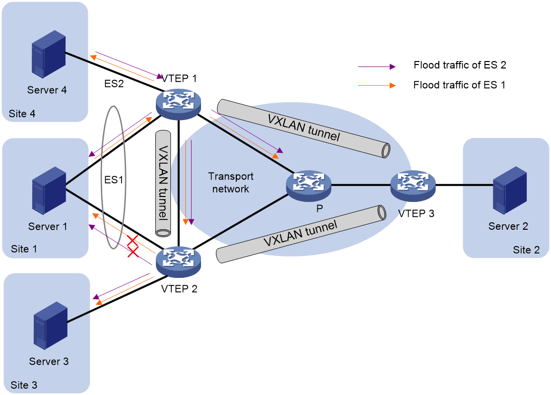
Split horizon
In a multihomed site, a VTEP forwards unknown multicast, broadcast, and unknown unicast frames received from ACs out of all site-facing interfaces and VXLAN tunnels in the corresponding VXLAN, except for the incoming interface. As a result, the other VTEPs at the site receive these flood frames and forward them to site-facing interfaces, which causes duplicate floods and loops. EVPN VXLAN introduces split horizon to resolve this issue. Split horizon disables a VTEP from forwarding flood traffic received from another local VTEP to site-facing interfaces if an ES on that local VTEP has the same ESI as these interfaces. As shown in Figure 16, both VTEP 1 and VTEP 2 have ES 1. When receiving flood traffic from VTEP 1, VTEP 2 does not forward the traffic to interfaces with ESI 1.
Redundancy mode
The Comware device supports the all-active redundancy mode of EVPN VXLAN multihoming. This mode allows all redundant VTEPs at a multihomed site to forward broadcast, unknown multicast, and unknown unicast traffic.
· For flood frames received from remotes sites, a VTEP forwards them to the ACs of which it is the DF.
· For flood frames received from the local site, a VTEP forwards them out of all site-facing interfaces and VXLAN tunnels in the corresponding VXLAN, except for the incoming interfaces. For flood frames to be sent out of a VXLAN tunnel interface, a VTEP replicates each flood frame and sends one replica to all the other VTEPs in the corresponding VXLAN.
IP aliasing
In all-active redundancy mode, all redundant VTEPs of an ES advertise the ES to remote VTEPs through MP-BGP. IP aliasing allows a remote VTEP to add the IP addresses of all the redundant VTEPs as the next hops for the MAC or ARP information received from one of these VTEPs. This mechanism creates ECMP routes between the remote VTEP and the redundant VTEPs.
EVPN VXLAN multicast
About EVPN VXLAN multicast
EVPN VXLAN uses BGP EVPN routes to advertise and withdraw multicast entries among VTEPs. In an EVPN VXLAN network, VTEPs create and maintain multicast forwarding entries based on received IGMP membership reports and leave group messages to reduce IGMP floods.
For more information about BGP EVPN routes for multicast forwarding, see "BGP EVPN routes."
Multicast in single-homed sites
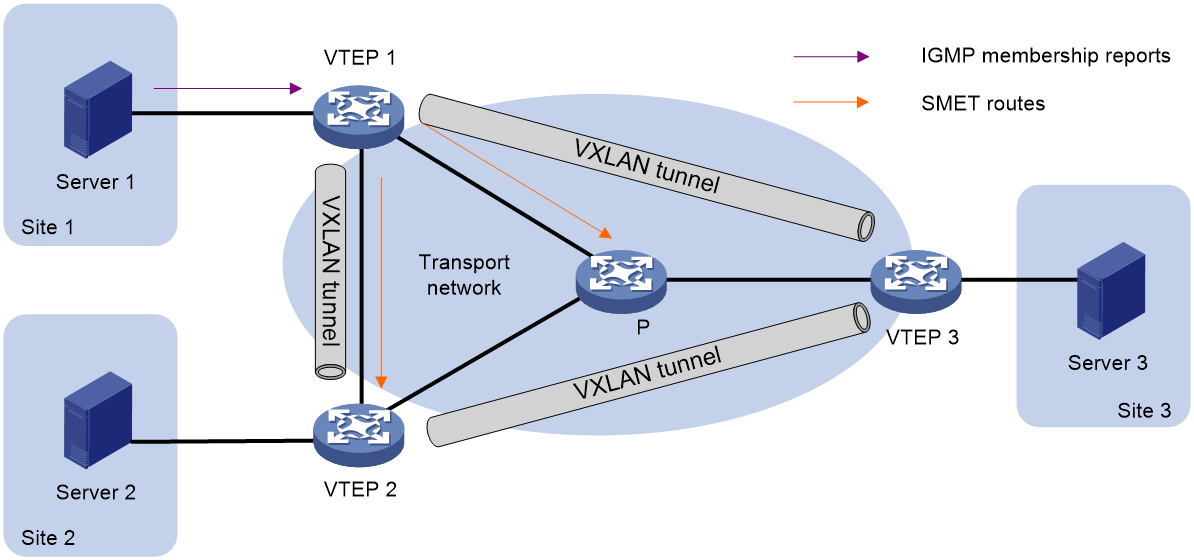
As shown in Figure 17, VTEPs at single-homed sites create multicast forwarding entries by using the following procedure:
1. VTEP 1 receives the IGMP membership report sent by Server 1.
2. VTEP 1 creates a multicast forwarding entry and advertises information about the multicast group to VTEP 2 and VTEP 3 through an SMET route.
3. VTEP 2 and VTEP 3 create multicast forwarding entries based on the SMET route. The next hop in the entries is VTEP 1.
Figure 17 Multicast in single-homed sites
Multicast in multihomed sites
The IGMP membership reports and leave group messages sent from a multihomed site are received by multiple VTEPs. To ensure consistency of multicast forwarding entries, redundant VTEPs advertise IGMP join synch and leave synch routes to synchronize multicast information for each ES.
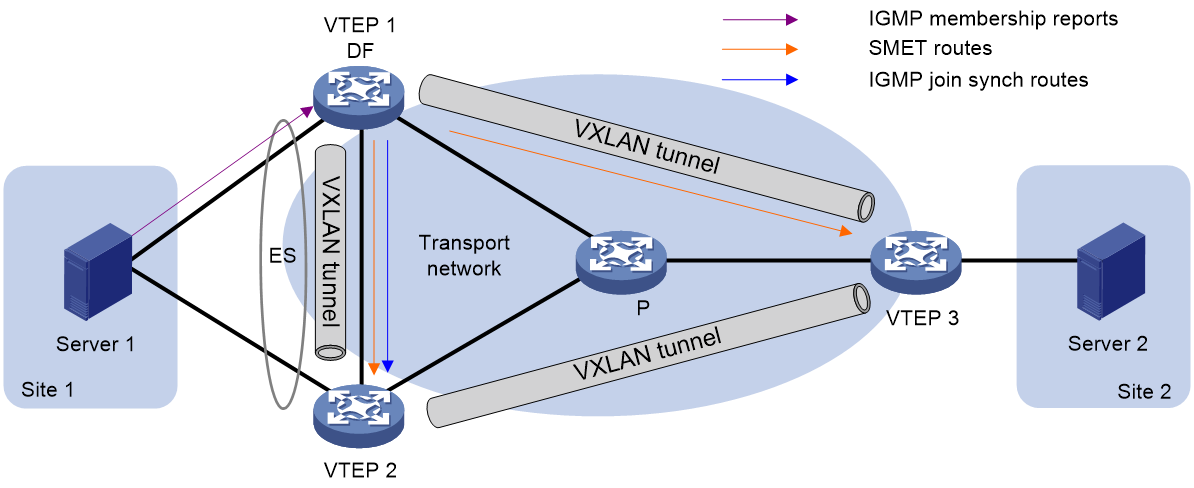
As shown in Figure 18, if the DF receives the first membership report for an IGMP multicast group, the following route advertisement and withdrawal process takes place:
1. VTEP 1 (DF) receives an IGMP membership report.
2. VTEP 1 sends an SMET route to VTEP 2 and VTEP 3, and sends an IGMP join synch route to VTEP 2.
3. An IGMP leave group message is sent from Site 1, and one of the following processes occurs:
¡ If VTEP 1 (DF) receives the message, it sends an IGMP leave synch route to VTEP 2 and withdraws the SMET route and IGMP join synch route that it has advertised.
¡ If VTEP 2 (BDF) receives the message, it sends an IGMP leave synch route to VTEP 1. Then VTEP 1 withdraws the SMET route and IGMP join synch route that it has advertised.
As shown in Figure 18, if the BDF receives the first membership report for an IGMP multicast group, the following route advertisement and withdrawal process takes place:
1. VTEP 2 (BDF) receives an IGMP membership report.
2. VTEP 2 sends an IGMP join synch route to VTEP 1 (DF).
3. VTEP 1 sends an SMET route to VTEP 2 and VTEP 3.
4. An IGMP leave group message is sent from Site 1, and one of the following processes occurs:
¡ If VTEP 1 (DF) receives the message, it sends an IGMP leave synch route to VTEP 2, and VTEP 2 withdraws the IGMP join synch route that it has advertised. Then, VTEP 1 withdraws the SMET route that it has advertised.
¡ If VTEP 2 (BDF) receives the message, it sends an IGMP leave synch route to VTEP 1 and withdraws the IGMP join synch route that it has advertised. Then, VTEP 1 withdraws the SMET route that it has advertised.
Figure 18 Multicast in multihomed sites
Application scenarios
Distributed EVPN gateway deployment
EVPN VXLAN has fewer requirements in traffic forwarding for a distributed EVPN gateway than a centralized EVPN gateway. In a distributed EVPN gateway network, the transport network devices only need to support typical IP forwarding. Thus, the distributed EVPN gateway service is widely used.
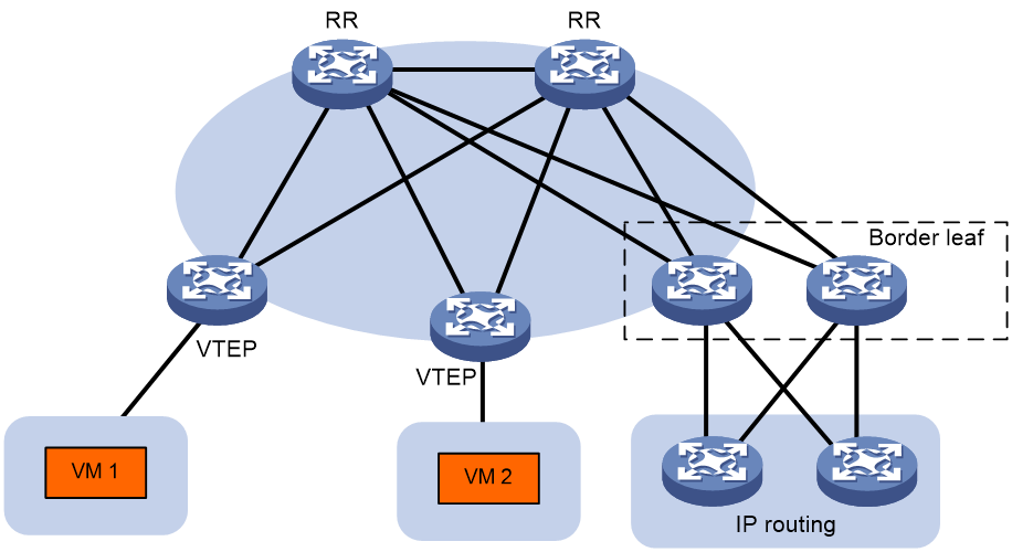
As shown in Figure 19, the VTEPs are distributed EVPN gateways. Redundant border leaves are deployed as the border gateways to connect the WAN. The RRs reflect BGP routes among the devices.
Figure 19 Distributed EVPN gateway deployment
EVPN-DCI deployment
EVPN data center interconnect (EVPN-DCI) uses VXLAN-DCI tunnels to provide connectivity for data centers over an IP transport network.
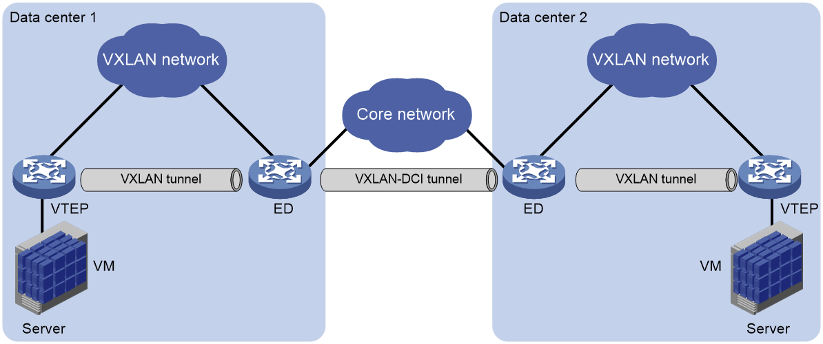
As shown in Figure 20, the EVPN-DCI network contains VTEPs and edge devices (EDs) located at the edge of the transport network. A VXLAN tunnel is established between a VTEP and an ED, and a VXLAN-DCI tunnel is established between two EDs. VXLAN-DCI tunnels use VXLAN encapsulation. Each ED de-encapsulates incoming VXLAN packets and re-encapsulates them based on the destination before forwarding the packets through a VXLAN or VXLAN-DCI tunnel.
Figure 20 EVPN-DCI network model
EVPN VXLAN deployment through an SDN controller
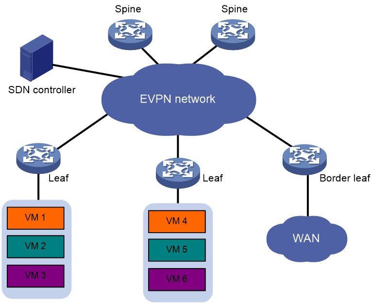
As shown in Figure 21, you can deploy an SDN controller to configure and manage EVPN VXLAN VTEPs and gateways in a centralized manner. This deployment reduces the configuration complexity of VTEPs and gateways. In addition, it facilitates network scalability and management.
Figure 21 EVPN VXLAN deployment through an SDN controller
References
· RFC 7432, BGP MPLS-Based Ethernet VPN
· draft-ietf-bess-evpn-overlay-02, A Network Virtualization Overlay Solution using EVPN
· draft-ietf-bess-evpn-prefix-advertisement-02, BGP MPLS-Based Ethernet VPN
· draft-ietf-bess-evpn-igmp-mld-proxy-01, IGMP and MLD Proxy for EVPN
