- Released At: 18-01-2021
- Page Views:
- Downloads:
- Table of Contents
- Related Documents
-
|
|
|
|
|
DRNI Technology White Paper |
|
|
Copyright © 2021 New H3C Technologies Co., Ltd. All rights reserved.
No part of this manual may be reproduced or transmitted in any form or by any means without prior written consent of New H3C Technologies Co., Ltd.
Except for the trademarks of New H3C Technologies Co., Ltd., any trademarks that may be mentioned in this document are the property of their respective owners.
This document provides generic technical information, some of which might not be applicable to your products.
The information in this document is subject to change without notice.
Contents
DR system setup and operating mechanisms
Keepalive and failover mechanism
Configuration consistency check
Forwarding user-side BUM traffic received on a non-DR interface
Forwarding BUM traffic received on a DR interface
Forwarding user-side unicast traffic received on a non-DR interface
Forwarding unicast traffic received on a DR interface
Forwarding BUM traffic received from the external network
Forwarding unicast traffic received from the external network
DR interface failure handling mechanism
IPL failure handling mechanism
Device failure handling mechanism
Uplink failure handling mechanism
DR system operating mechanisms
Independent BGP neighbor relationship establishment
Communication between single-homed ACs
Single-tier deployment of a DR system
Multitier deployment of DR systems for network expansion
Overview
In addition to the benefits of link aggregation, such as high bandwidth, link redundancy, and load sharing, DRNI provides the following benefits:
· Node redundancy. When one node fails, the other node can take over to forward traffic.
· Loop-free Layer 2 topology without having to run a spanning tree protocol.
· Simplified network configuration and maintenance, thanks to the removal of spanning tree configuration.
· Service continuity during software upgrade of one member in the multichassis link aggregation system.
DRNI implementation
DRNI network model
As shown in Figure 1, DRNI virtualizes two devices into a distributed-relay (DR) system, which connects to the remote aggregation system through a multichassis aggregate link. To the remote aggregation system, the DR system is one device. Failure of one device in the DR system does not interrupt traffic forwarding.
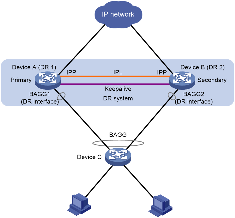
The DR member devices are DR peers to each other. For features that require centralized traffic processing (for example, spanning tree), a DR member device is assigned the primary or secondary role based on its DR role priority. The secondary DR device passes the traffic of those features to the primary DR device for processing. If the DR member devices in a DR system have the same DR role priority, the device with the lower bridge MAC address is assigned the primary role.
DRNI defines the following interface roles for each DR member device:
· DR interface—Layer 2 aggregate interface connected to the remote aggregation system. DR interfaces connected to the same remote aggregation system belong to one DR group. In Figure 1, Bridge-Aggregation 1 on Device A and Bridge-Aggregation 2 on Device B belong to the same DR group. DR interfaces in a DR group form a multichassis aggregate link.
· Intra-portal port (IPP)—Interface connected to the DR peer for internal control. Each DR member device has only one IPP. The IPPs of the DR member devices transmit DRNI protocol packets and data packets through the intra-portal link (IPL) established between them. A DR system has only one IPL.
DR system setup and operating mechanisms
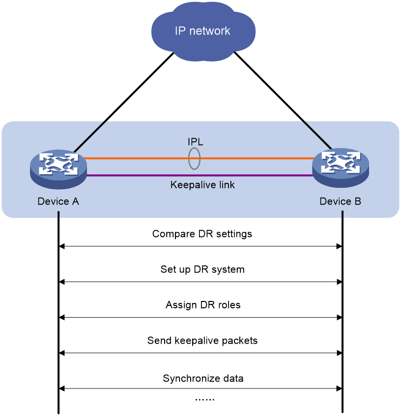
DR member devices exchange distributed relay control protocol data units (DRCPDUs) and keepalive packets to set up the DR system and ensure correct operation of the DR system.
DR system setup process
As shown in Figure 2, two devices perform the following operations to form a DR system:
1. Send DRCPDUs over the IPL to each other and compare the DRCPDUs to determine the DR system stackability and device roles:
a. Compare the DR system settings. The devices can form a DR system if they have the same DR system MAC address and system priority and different DR system numbers.
b. Determine the device roles based on the DR role priority and the bridge MAC address.
c. Perform configuration consistency check.
2. Send keepalive packets over the keepalive link after primary DR member election to verify that the peer system is operating correctly.
3. Synchronize configuration data by sending DRCPDUs over the IPL. The configuration data includes MAC address entries and ARP entries.
Figure 2 DR system setup process
DRCP
DRNI uses IEEE P802.1AX Distributed Relay Control Protocol (DRCP) for multichassis link aggregation. DRCP runs on the IPL and uses DRCPDUs to advertise the DRNI configuration out of IPPs and DR interfaces.
DRCP operating mechanism
DRNI-enabled devices use DRCPDUs for the following purposes:
· Exchange DRCPDUs through DR interfaces to determine whether they can form a DR system.
· Exchange DRCPDUs through IPPs to negotiate the IPL state.
DRCP timeout timers
DRCP uses a timeout mechanism to specify the amount of time that an IPP or DR interface must wait to receive DRCPDUs before it determines that the peer interface is down. This timeout mechanism provides the following timer options:
· Short DRCP timeout timer, which is fixed at 3 seconds. If this timer is used, the peer interface sends one DRCPDU every second.
· Long DRCP timeout timer, which is fixed at 90 seconds. If this timer is used, the peer interface sends one DRCPDU every 30 seconds.
Short DRCP timeout timer enables the DR member devices to detect a peer interface down event more quickly than the long DRCP timeout timer. However this benefit is at the expense of bandwidth and system resources.
Keepalive and failover mechanism
The secondary DR device uses a Layer 3 keepalive link between the DR member devices to monitor the state of the primary device.
The DR member devices periodically send keepalive packets over the keepalive link. If a DR member device has not received keepalive packets from the peer when the keepalive timeout timer expires, it determines that the keepalive link is down. When both the keepalive link and the IPL are down, a DR member device acts depending on its role.
· If its role is primary, the device retains its role as long as it has up DR interfaces. If all its DR interfaces are down, its role becomes None.
· If its role is secondary, the device takes over the primary role and retains the role as long as it has up DR interfaces. If all its DR interfaces are down, its role becomes None.
A device with the None role cannot send or receive keepalive packets. Its keepalive link will stay in down state until the DR system recovers.
If the keepalive link is down while the IPL is up, the DR member devices prompt you to check for keepalive link issues.
If the keepalive link is up while the IPL is down, the DR member devices elect a primary device based on the information in the keepalive packets.
MAD
MAD operating mechanism
A multi-active collision occurs if the IPL goes down while the keepalive link is up. To avoid network issues, DRNI MAD takes one of the following actions on the secondary DR member device when the DR system splits:
· DRNI MAD DOWN—Shut down all network interfaces except the interfaces excluded manually or by the system.
· NONE—Do not shut down any network interfaces except the interfaces configured manually or by the system to be shut down by DRNI MAD.
When the IPL comes up, the secondary DR member device starts a delay timer and begins to restore table entries (including MAC address entries and ARP entries) from the primary DR member device. When the delay timer expires, the secondary DR member device brings up all network interfaces placed in DRNI MAD DOWN state.
MAD configuration methods
To retain only special-purpose interfaces in up state on the secondary DR member device when the DR system splits, configure DRNI MAD to take the DRNI MAD DOWN action. DRNI MAD will shut down all network interfaces except the following:
· Interfaces automatically excluded from being shut down by DRNI MAD. These interfaces are the IPP, DR interfaces, management interfaces, and aggregation member interfaces if a Layer 2 aggregate interface is used as the IPP.
· Interfaces manually excluded from being shut down by DRNI MAD.
· Interfaces manually or automatically excluded from being shut down by IRF MAD.
· Network interfaces forced to stay in up state.
To have the secondary DR member device retain a large number of interfaces in up state and shut down the remaining interfaces, configure DRNI MAD to take the NONE action. DRNI MAD will shut down only the network interfaces that are configured manually or by the system to be shut down by DRNI MAD. One applicable scenario of this method is the EVPN environment in which you use a VXLAN tunnel as the IPL. In this scenario, you must retain a large number of logical interfaces (for example, tunnel and loopback interfaces) in up state.
Configuration consistency check
During DR system setup, DR member devices exchange the configuration and perform configuration consistency check to verify their consistency in the following configurations:
· Type 1 configuration—Settings that affect traffic forwarding of the DR system. If an inconsistency in type 1 configuration is detected, the secondary DR device shuts down its DR interfaces.
· Type 2 configuration—Settings that affect only service features. If an inconsistency in type 2 configuration is detected, the secondary DR device disables the affected service features, but it does not shut down its DR interfaces.
To prevent interface flapping, the DR system performs configuration consistency check when half the data restoration internal elapses.
|
|
NOTE: The data restoration interval specifies the maximum amount of time for the secondary DR member device to synchronize data with the primary DR member device during DR system setup. |
Type 1 configuration
Type 1 configuration consistency check is performed both globally and on DR interfaces. Table 1 and Table 2 show settings that type 1 configuration contains.
Table 1 Global type 1 configuration
|
Setting |
Details |
|
IPP link type |
IPP link type, including access, hybrid, and trunk. |
|
PVID on the IPP |
PVID on the IPP. |
|
Spanning tree state |
· Global spanning tree state. · VLAN-specific spanning tree state. |
|
Spanning tree mode |
Spanning tree mode, including STP, RSTP, PVST, and MSTP. |
|
MST region settings |
· MST region name. · MST region revision level. · VLAN-to-MSTI mappings. |
Table 2 DR interface type 1 configuration
|
Setting |
Details |
|
Aggregation mode |
Aggregation mode, including static and dynamic. |
|
Spanning tree state |
Interface-specific spanning tree state. |
|
Link type |
Interface link type, including access, hybrid, and trunk. |
|
PVID |
Interface PVID. |
Type 2 configuration
Type 2 configuration consistency check is performed both globally and on DR interfaces. Table 3 and Table 4 show settings that type 2 configuration contains.
Table 3 Global type 2 configuration
|
Setting |
Details |
|
VLAN interfaces |
Up VLAN interfaces of which the VLANs contain the IPP. |
|
Passing tagged VLANs or passing PVID |
VLANs of which the IPP forwards tagged traffic or PVID of which the IPP forwards traffic. |
Table 4 DR interface type 2 configuration
|
Setting |
Details |
|
Passing tagged VLANs |
VLANs of which a DR interface forwards tagged traffic. |
|
Passing untagged VLANs |
VLANs of which a DR interface forwards untagged traffic. |
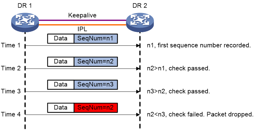
DRNI sequence number check
DRNI sequence number check protects DR member devices from replay attacks.
As shown in Figure 3, with this feature enabled, the DR member devices insert a sequence number into each outgoing DRCPDU or keepalive packet and the sequence number increases by 1 for each sent packet. When receiving a DRCPDU or keepalive packet, the DR member devices check its sequence number and drop the packet if the check result is either of the following:
· The sequence number of the packet is the same as that of a previously received packet.
· The sequence number of the packet is smaller than that of the most recently received packet.
Figure 3 DRNI sequence number check
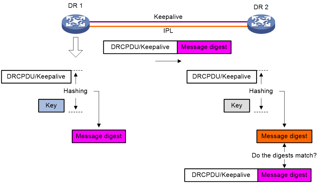
DRNI packet authentication
DRNI packet authentication prevents DRCPDU and keepalive packet tampering from causing link flapping.
As shown in Figure 4, with this feature enabled, the DR member devices compute a message digest by using an authentication key for each outgoing DRCPDU or keepalive packet and insert the message digest into the packet. When receiving a DRCPDU or keepalive packet, a DR member device computes a message digest and compares it with the message digest in the packet. If the message digests match, the packet passes authentication. If the message digests do not match, the device drops the packet.
Figure 4 DRNI packet authentication
Traffic forwarding
Forwarding user-side BUM traffic received on a non-DR interface
To avoid forwarding duplicate traffic to the remote aggregate system, a DR member device does not forward the traffic received on the IPP out of DR interfaces.
As shown in Figure 5, when receiving broadcast, unknown unicast, and unknown multicast (BUM) traffic from Device A, Device D forwards the traffic out of all its interfaces. When the traffic arrives at Device E over the IPL, Device E forwards the traffic out of all its interfaces except for the DR interface.
Figure 5 Forwarding user-side BUM traffic received on a non-DR interface
Forwarding BUM traffic received on a DR interface
The BUM traffic sent from the remote aggregation system is load shared across the links connected to the DR system. As shown in Figure 6, when receiving BUM traffic from Device B, Device D forwards the traffic out of all its interfaces. When the traffic arrives at Device E over the IPL, Device E forwards the traffic out of all its interfaces except for the DR interface.
Figure 6 Forwarding BUM traffic received on a DR interface

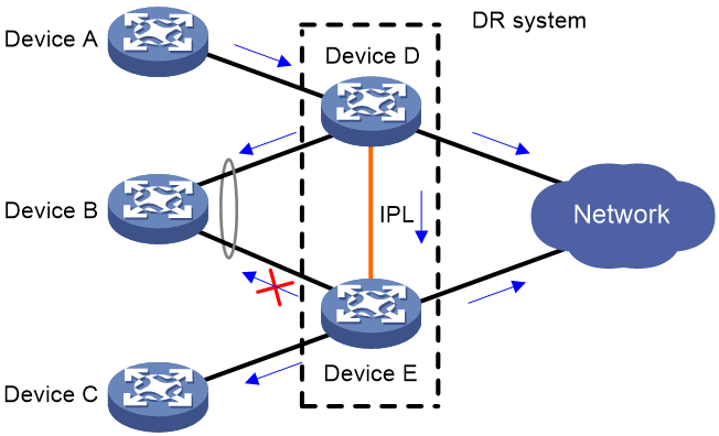
Forwarding user-side unicast traffic received on a non-DR interface
DR member devices perform local-first forwarding for unicast traffic received on a non-DR interface. With local-first forwarding, a DR member device does not forward the unicast traffic to the IPL as long as a local outgoing port other than IPP is available. As shown in Figure 7, when receiving unicast traffic from Device A to the external network, Device D forwards the traffic locally if it has an outgoing port other than IPP to the external network.
Figure 7 Forwarding user-side unicast traffic received on a non-DR interface
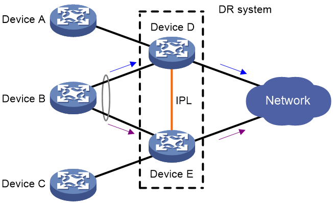
Forwarding unicast traffic received on a DR interface
The unicast traffic sent from the remote aggregation system is load shared across the member links of the multichassis aggregate link. When forwarding unicast traffic, the DR member devices perform local-first forwarding. They do not forward the unicast traffic to the IPL as long as a local outgoing port other than IPP is available.
As shown in Figure 8, Device D and Device E each have an outgoing port to the external network. When they receive unicast traffic sent by Device B to the external network, they forward the received packets out of their local outgoing port.
Figure 8 Forwarding unicast traffic received on a DR interface
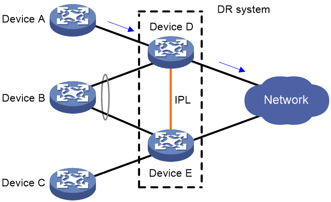
Forwarding BUM traffic received from the external network
The BUM traffic sent from the external network is not distributed across the links connected to the DR system. As shown in Figure 9, when receiving BUM traffic from the external network, Device D forwards the traffic out of all its interfaces. When the traffic arrives at Device E over the IPL, Device E forwards the traffic out of all its interfaces except for the DR interface.
Figure 9 Forwarding BUM traffic received from the external network

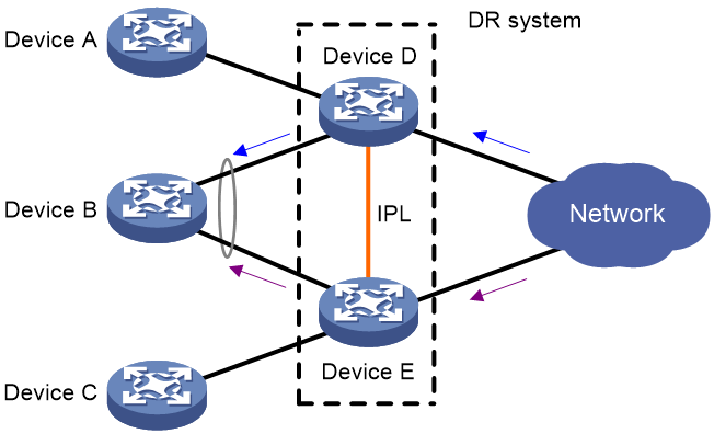
Forwarding unicast traffic received from the external network
As shown in Figure 10, when receiving unicast traffic to Device B, both Device D and Device E forward the traffic out of their DR interfaces.
Figure 10 Forwarding unicast traffic to the remote aggregation system
As shown in Figure 11, when receiving unicast traffic to Device A (attached to a non-DR interface), Device D forwards the traffic locally.
Figure 11 Forwarding unicast traffic to a non-aggregation peer

Failure handling mechanisms
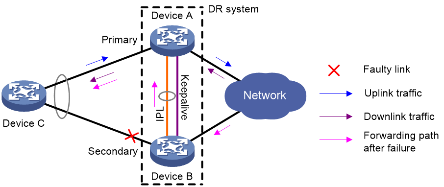
DR interface failure handling mechanism
When the DR interface of one DR member device fails, the DR system forwards traffic through the other DR member device.
As shown in Figure 12, Device A and Device B form a DR system, to which Device C is attached through a multichassis aggregate link. If traffic to Device C arrives at Device B after the DR interface connected Device B to Device C has failed, the DR system forwards the traffic as follows:
1. Device B sends the traffic to Device A over the IPL.
2. Device A forwards the downlink traffic received from the IPL to Device C.
After the faulty DR interface comes up, Device B forwards traffic to Device C through the DR interface.
Figure 12 DR interface failure handling mechanism
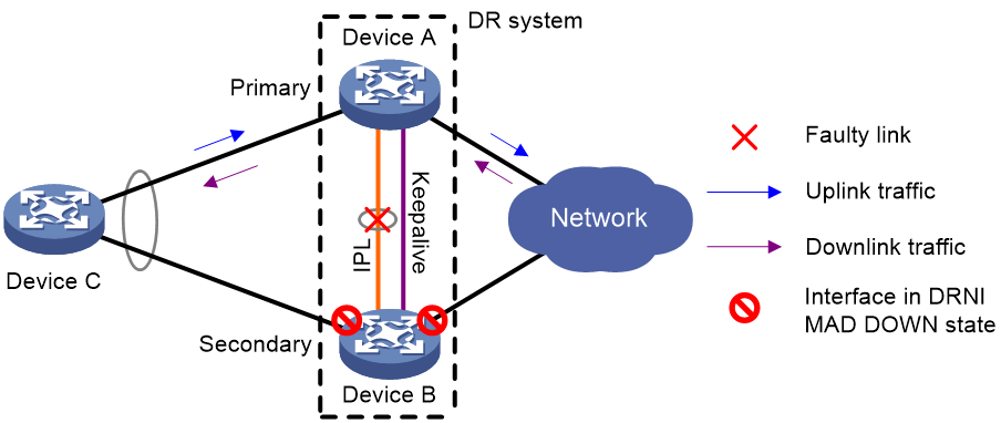
IPL failure handling mechanism
As shown in Figure 13, multi-active collision occurs if the IPL goes down while the keepalive link is up. To avoid network issues, the secondary DR device sets all network interfaces to DRNI MAD DOWN state, except for the following interfaces:
· Interfaces excluded from the MAD shutdown action by IRF.
· Interfaces excluded from the MAD shutdown action by DRNI.
In this situation, the primary DR device forwards all traffic for the DR system.
When the IPP comes up, the secondary DR device does not bring up the network interfaces immediately. Instead, it starts a delay timer and begins to recover data from the primary DR device. When the delay timer expires, the secondary DR device brings up all network interfaces.
Figure 13 IPL failure handling mechanism
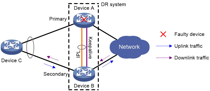
Device failure handling mechanism
As shown in Figure 14, when the primary DR device fails, the secondary DR device takes over the primary role to forward all traffic for the DR system. When the faulty device recovers, it becomes the secondary DR device.
When the secondary DR device fails, the primary DR device forwards all traffic for the DR system.
Figure 14 Device failure handling mechanism
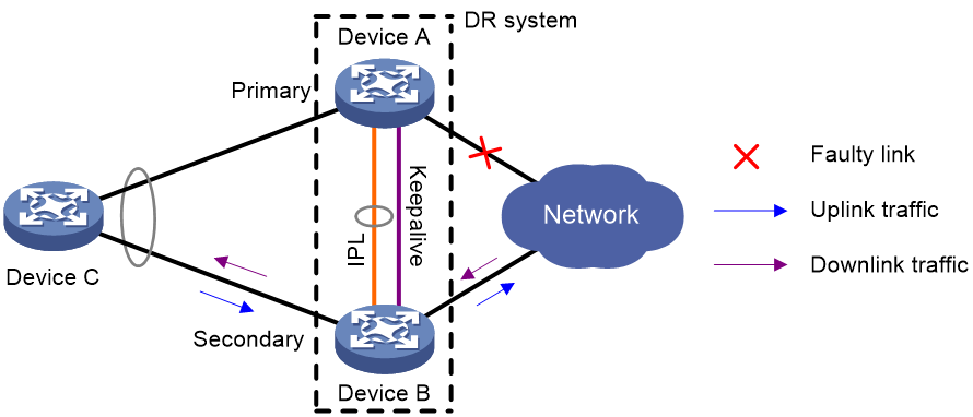
Uplink failure handling mechanism
Uplink failure does not interrupt traffic forwarding of the DR system. As shown in Figure 15, when the uplink of Device A fails, Device A passes traffic destined for the IP network to Device B for forwarding.
To enable faster traffic switchover in response to an uplink failure and minimize traffic losses, configure Monitor Link to associate the DR interfaces with the uplink interfaces. When the uplink interface of a DR member device fails, that device shuts down its DR interface for the other DR member device to forward all traffic of Device C.
Figure 15 Uplink failure handling mechanism
Application of DRNI in EVPN
About DRNI in EVPN
You can use DRNI in Ethernet Virtual Private Network (EVPN) to virtualize two VTEPs or EVPN gateways into one DR system to avoid single points of failure. At the time of this writing, you can set up EVPN distributed relay (DR) systems only at IPv4 sites.
Figure 16 EVPN distributed relay
DR system operating mechanisms
Virtual VTEP address
The DR member devices use a virtual VTEP address to set up VXLAN tunnels with remote VTEPs or EVPN gateways.
Independent BGP neighbor relationship establishment
The DR member devices use different BGP peer addresses to establish neighbor relationships with remote devices. For load sharing and link redundancy, a neighbor sends traffic destined for the virtual VTEP address to both of the DR member devices through ECMP routes of the underlay network.
Entry synchronization
To ensure VM reachability information consistency in the EVPN DR system, the DR member devices synchronize MAC address entries and ARP information with each other through the IPL. The IPL can be an Ethernet aggregate link or a VXLAN tunnel. The VXLAN tunnel that acts as the IPL is automatically associated with all VXLANs on each DR member device.
BGP EVPN route advertisement
VTEPs use BGP EVPN routes to discover VTEP neighbors, establish VXLAN tunnels, assign the tunnels to VXLANs, and advertise MAC/IP reachability information.
The next hop for the inclusive multicast Ethernet tag (IMET) routes advertised by a DR member device varies by IPL type.
· If the IPL is an Ethernet aggregate link, the next hop for the IMET routes is the virtual VTEP address. Each IMET route traverses a VXLAN tunnel established between the virtual VTEP address and a remote VTEP address.
· If the IPL is a VXLAN tunnel, a DR member device advertises two IMET routes with different next hops to each remote VTEP. One route uses the virtual VTEP address as the next hop, and the other uses the local BGP peer address as the next hop. The routes traverse the following VXLAN tunnels:
¡ The VXLAN tunnel established between the virtual VTEP address and the remote VTEP address.
¡ The VXLAN tunnel established between the local BGP peer address and the remote VTEP address.
When advertising MAC and ARP entries in MAC/IP advertisement routes, a DR member device uses different next hops depending on the type of the learning interface:
· The next hop is the virtual VTEP address if the entries were learned on DR interfaces.
· The next hop is the local BGP peer address if the entries were learned on non-DR interfaces.
The next hop is the local BGP peer address in IP prefix advertisement routes advertised by a DR member device.
Site-facing link redundancy
A VTEP uses an Ethernet service instance to match customer traffic on a site-facing interface. An Ethernet service instance is identical to an attachment circuit (AC) in L2VPN. It matches a list of VLANs on a Layer 2 interface by using a frame match criterion. The frame match criterion specifies the characteristics of traffic from the VLANs, such as tagging status and VLAN IDs.
To provide site-facing link redundancy to a VM:
· Connect the VM to the EVPN DR system through multiple Ethernet links.
· On each DR member device, assign all site-facing Ethernet links to the Layer 2 aggregation group of the DR interface.
· Configure identical Ethernet service instances as ACs on the DR interfaces of the DR member devices.
The site-facing link backup mechanism differs depending on the IPL type.
· If the IPL is an Ethernet aggregate link, the site-facing link backup mechanism is as follows:
When a site-facing AC is configured on the DR interface of a DR member device, the device automatically creates an AC with the same frame match criterion as the site-facing AC on the IPL. Then, it maps the IPL AC to the VSI of the site-facing AC. When the site-facing AC is down, the device forwards the traffic that a remote VTEP sends to the AC to the other DR member device over the IPL. This mechanism ensures service continuity in case of AC failure.
· If the IPL is a VXLAN tunnel, the site-facing link backup mechanism is as follows when a site-facing AC on a DR member device is down:
The member device re-encapsulates the remote traffic destined for the failed AC into VXLAN packets with the AC's VXLAN ID and sends them over the IPL to its peer DR member device. Then, the peer DR member device assigns the packets to the correct VSI based on the VXLAN ID and forwards them.
Communication between single-homed ACs
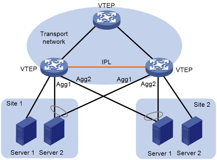
An AC attached to only one of the VTEPs in a DR system is called a single-homed AC. As shown in Figure 17, Server 1 at site 1 and Server 2 at site 2 are attached to the DR system through single-homed ACs. Two single-homed ACs communicate through the IPL.
· If the IPL is an aggregate link, the DR system creates a dynamic AC for each single-homed AC at both ends of the IPL. The dynamic ACs have the same frame match criterion and VSI mapping as their associated single-homed ACs. When receiving packets from a single-homed AC, a VTEP forwards them to the peer VTEP over the IPL. The peer VTEP identifies the VSI to which the packets belong based on the matching dynamic AC and then forwards them.
· If the IPL is a VXLAN tunnel, a VTEP encapsulates the packets received from a single-homed AC and forwards them to the peer VTEP over the IPL. The packets are encapsulated with the VXLAN ID of the VSI to which the packets belong. The peer VTEP identifies the VSI to which the packets belong by the VXLAN ID and then forwards the packets.
Figure 17 Communication between single-homed ACs

Traffic forwarding
An EVPN DR system uses the same forwarding process as DRNI for unicast traffic. However, its forwarding process for BUM traffic received on the IPP is different from DRNI.
As shown in Figure 18, when BUM traffic from Server 1 arrives at the EVPN DR system, VTEP 1 forwards the traffic out of all interfaces in the matching VXLAN, except for the incoming interface. When the traffic arrives at VTEP 2, VTEP 2 forwards the traffic only out of site-facing non-DR interfaces in the VXLAN.
Figure 18 Forwarding BUM traffic
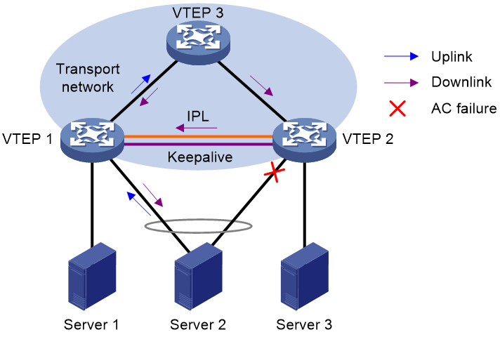
Failure handling
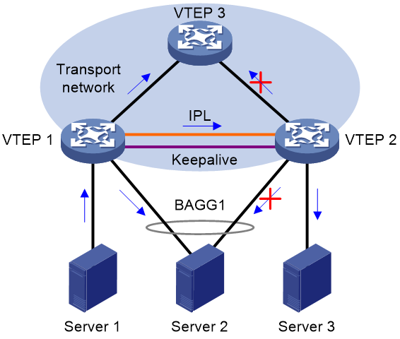
When an AC on the DR interface of one DR member device fails, the EVPN DR system forwards traffic through the other DR member device.
As shown in Figure 19, VTEP 1 and VTEP 2 form an EVPN DR system, to which Server 2 is attached through a multichassis aggregate link. The EVPN DR system uses an Ethernet aggregate link as the IPL. If the site-facing AC on the DR interface of VTEP 2 fails, the EVPN DR system forwards the remote traffic destined for Server 2 as follows:
1. VTEP 2 assigns the traffic to the IPL AC and forwards the traffic to VTEP 1 over the IPL.
2. VTEP 1 identifies the VSI for the traffic based on the IPL AC and forwards the traffic to Server 2.
After the failed AC comes up, VTEP 2 forwards traffic to Server 2 through the DR interface.
Figure 19 AC failure handling (Ethernet aggregate link as IPL)
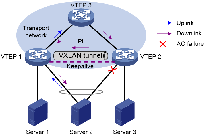
As shown in Figure 20, VTEP 1 and VTEP 2 form an EVPN DR system, to which Server 2 is attached through a multichassis aggregate link. The EVPN DR system uses a VXLAN tunnel as the IPL. If the site-facing AC on the DR interface of VTEP 2 fails, the EVPN DR system forwards the remote traffic destined for Server 2 as follows:
1. VTEP 2 adds VXLAN encapsulation to the traffic and forwards the traffic to VTEP 1 over the IPL. The encapsulated VXLAN ID is that of the failed AC.
2. VTEP 1 identifies the VSI for the traffic based on the encapsulated VXLAN ID and forwards the traffic to Server 2.
After the failed AC comes up, VTEP 2 forwards traffic to Server 2 through the DR interface.
Figure 20 AC failure handling (VXLAN tunnel as IPL)
Application scenarios
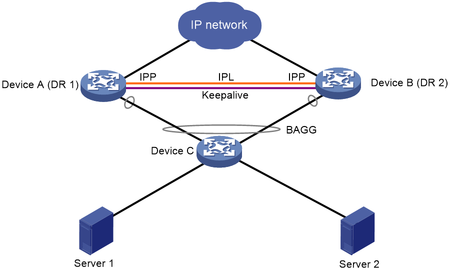
Single-tier deployment of a DR system
As shown in Figure 21, configure Device A and Device B into a DR system, and connect Device C to the DR system through a multichassis aggregate link. The DR system can load share traffic across the redundant links and ensure service continuity when one of the DR member device fails.
Figure 21 Typical DRNI network
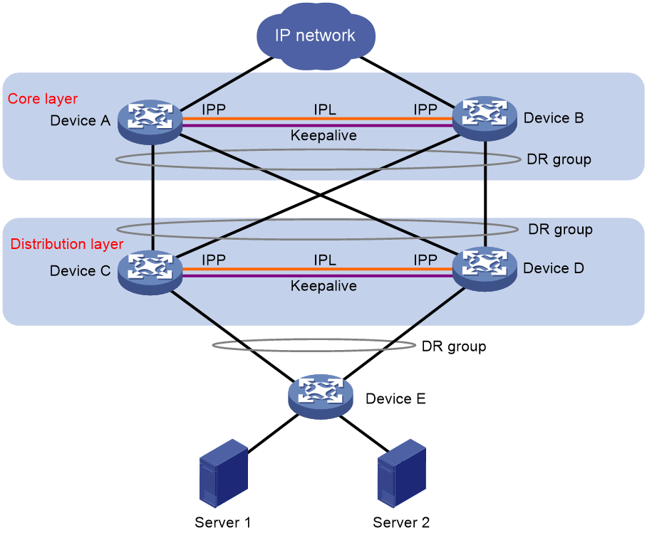
Multitier deployment of DR systems for network expansion
You can configure DRNI at two adjacent layers of a large data center to expand the network and provide a stable network environment.
As shown in Figure 22, deploy one DR system at the distribution layer (also called the aggregation layer) for gateway redundancy, and deploy another DR system at the core layer. Connect the DR systems through multichassis aggregate links to enhance service availability.
Figure 22 Multiple interconnected DR systems
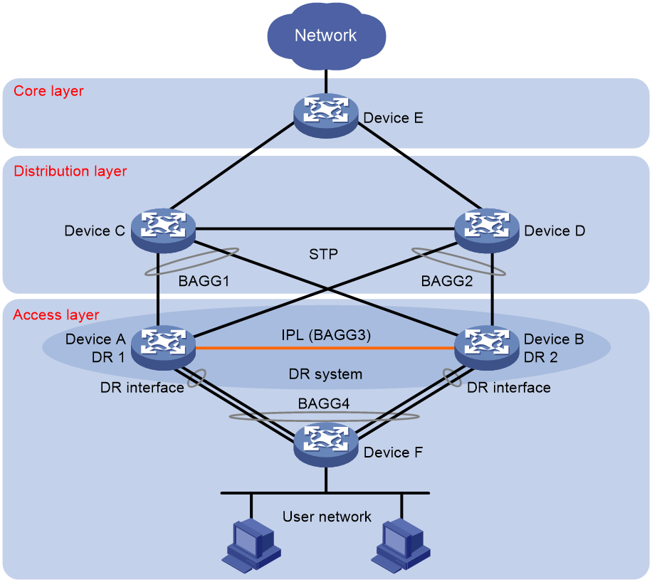
DRNI with STP
As shown in Figure 23, you can configure DRNI at the access layer for high availability and load sharing and configure STP between the access layer and the distribution layer to eliminate loops.
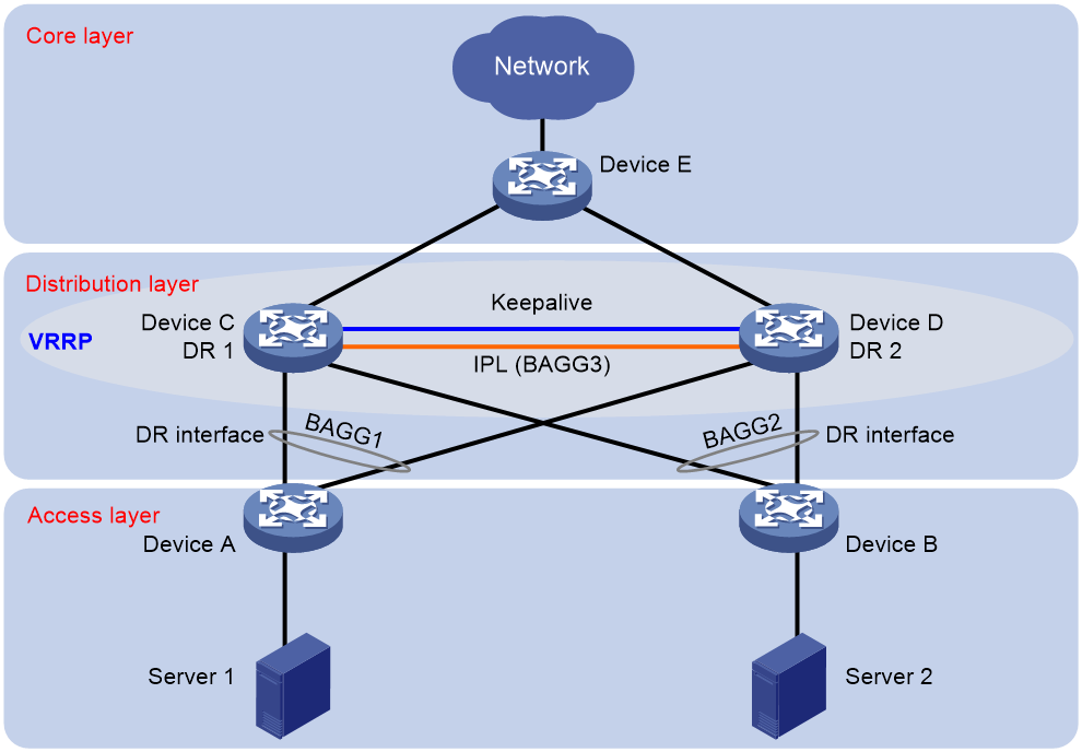
DRNI with VRRP
As shown in Figure 24, configure DRNI for high availability and load sharing and standard-mode VRRP for gateway redundancy at the distribution layer. The DR system load shares user traffic across redundant links. You do not need to configure VRRP load balancing mode.
EVPN DR system
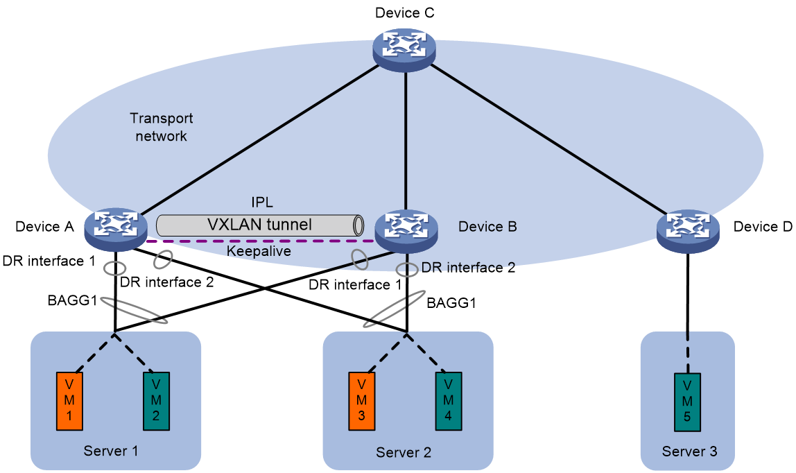
As shown in Figure 25 and Figure 26, deploy an EVPN DR system to virtualize two VTEPs or EVPN gateways into one system through DRNI to avoid single points of failure. Connect downstream servers to the EVPN DR system through a multichassis aggregate link formed by redundant site-facing links. The IPL can be an Ethernet aggregate link or VXLAN tunnel.
The DR member devices will synchronize MAC and ARP information through the IPL to have consistent forwarding entries.
Figure 25 EVPN distributed relay (Ethernet aggregate link as IPL)
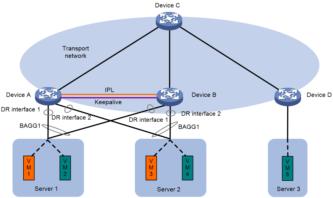
Figure 26 EVPN distributed relay (VXLAN tunnel as IPL)
References
· IEEE P802.1AX-REV™/D4.4c, Draft Standard for Local and Metropolitan Area Networks
· RFC 7432, BGP MPLS-Based Ethernet VPN
