| Title | Size | Downloads |
|---|---|---|
| H3C S6850 & S9850 Switch Series Hardware Information and Specifications-6W100-book.pdf | 2.87 MB |
- Related Documents
-
1 Product models and technical specifications
Product models
The H3C S6850 Switch Series and S9850 Switch Series are high-density intelligent 100G access switches with powerful hardware forwarding capacity and abundant data center features. They are developed for data centers and high-end campus networks.
The H3C S6850 Switch Series includes the following models:
· S6850-56HF
· S6850-2C
The H3C S9850 Switch Series includes the following models:
· S9850-4C
· S9850-32H
The switch provides the following ports and FRUs:
· 100G QSFP28 ports, 40G QSFP+ ports, 25GE SFP28 ports, and 10G SFP+ ports.
· Two 1G management Ethernet ports (one fiber port and one copper port).
· Removable fan trays in redundancy mode and flexible airflows.
· Removable power modules in redundancy mode.
Technical specifications
Table1-1 H3C S6850 switch series technical specifications
|
Item |
S6850-56HF |
S6850-2C |
|
Product code |
· LS-6850-56HF · LS-6850-56HF-H1 |
LS-6850-2C |
|
Dimensions (H × W × D) |
43.6 × 440 × 460 mm (1.72 × 17.32 × 18.11 in) |
44.2 × 440 × 660 mm (1.74 × 17.32 × 25.98 in) |
|
Weight |
≤ 15 kg (33.07 lb) |
≤ 16 kg (35.27 lb) |
|
Console ports |
· 1 × Mini USB console port · 1 × serial console port |
· 1 × Mini USB console port · 1 × serial console port |
|
Management Ethernet ports |
· 1 × 10M/100M/1000MBASE-T copper port · 1 × SFP port |
· 1 × 10M/100M/1000MBASE-T copper port · 1 × SFP port |
|
USB ports |
1 |
1 |
|
SFP ports |
2 |
N/A |
|
SFP28 ports |
48 |
N/A |
|
QSFP28 ports |
8 |
2 |
|
Fan tray slots |
5 |
5 |
|
Power module slots |
2 |
2 |
|
Expansion slots |
N/A |
2 |
|
Minimum power consumption (For the power consumption data collection standard, see Table1-3) |
· Single AC input: 167 W · Dual AC inputs: 179 W · Single DC input: 154 W · Dual DC inputs: 174 W |
· Single AC input: 136 W · Dual AC inputs: 148 W · Single DC input: 132 W · Dual DC inputs: 146 W |
|
Typical power consumption (For the power consumption data collection standard, see Table1-3) |
· Single AC input: 201 W · Dual AC inputs: 224 W · Single DC input: 198 W · Dual DC inputs: 210 W |
· Single AC input: 273 W · Dual AC inputs: 282 W · Single DC input: 268 W · Dual DC inputs: 275 W |
|
Maximum power consumption (For the power consumption data collection standard, see Table1-3) |
· Single AC input: 405 W · Dual AC inputs: 413 W · Single DC input: 400 W · Dual DC inputs: 408 W |
· Single AC input: 408 W · Dual AC inputs: 421 W · Single DC input: 404 W · Dual DC inputs: 411 W |
|
Chassis leakage current compliance |
· UL60950-1 · EN60950-1 · IEC60950-1 · GB4943 |
|
|
Sound pressure level at 27°C (80.6°F) |
62.1 dB(A) |
61.3 dB(A) |
|
Operating temperature |
0°C to 45°C (32°F to 113°F) |
|
|
Operating humidity |
5% RH to 95% RH, noncondensing |
|
|
Fire resistance compliance |
· UL60950-1 · EN60950-1 · IEC60950-1 · GB4943 |
|
Table1-2 H3C S9850 switch series technical specifications
|
Item |
S9850-4C |
S9850-32H |
|
|
Product code |
LS-9850-4C |
LS-9850-32H-A |
|
|
Dimensions (H × W × D) |
88.1 × 440 × 660 mm (3.47 × 17.32 × 25.98 in) |
43.6 × 440 × 460 mm (1.72 × 17.32 × 18.11 in) |
|
|
Weight |
≤ 27 kg (59.52 lb) |
≤ 15 kg (33.07 lb) |
|
|
Console ports |
· 1 × Mini USB console port · 1 × serial console port |
· 1 × Mini USB console port · 1 × serial console port |
|
|
Management Ethernet ports |
· 1 × 10M/100M/1000MBASE-T copper port · 1 × SFP port |
· 1 × 10M/100M/1000MBASE-T copper port · 1 × SFP port |
|
|
USB ports |
1 |
1 |
|
|
SFP ports |
2 |
2 |
|
|
QSFP28 ports |
N/A |
32 |
|
|
Fan tray slots |
2 |
5 |
|
|
Power module slots |
4 |
2 |
|
|
Expansion slots |
4 |
N/A |
|
|
Minimum power consumption (For the power consumption data collection standard, see Table1-3) |
· Dual AC inputs: 152 W · Triple AC inputs: 169 W · Quadruple AC inputs: 185 W · Dual DC inputs: 159 W · Triple DC inputs: 174 W · Quadruple DC inputs: 185 W |
· Single AC input: 154 W · Dual AC inputs: 166 W · Single DC input: 154 W · Dual DC inputs: 163 W |
|
|
Typical power consumption (For the power consumption data collection standard, see Table1-3) |
· Dual AC inputs: 355 W · Dual DC inputs: 361 W |
· Single AC input: 198 W · Dual AC inputs: 210 W · Single DC input: 197 W · Dual DC inputs: 208 W |
|
|
Maximum power consumption (For the power consumption data collection standard, see Table1-3) |
· Dual AC inputs: 665 W · Triple AC inputs: 671 W · Quadruple AC inputs: 688 W · Dual DC inputs: 663 W · Triple DC inputs: 665 W · Quadruple DC inputs: 666 W |
· Single AC input: 376 W · Dual AC inputs: 385 W · Single DC input: 373 W · Dual DC inputs: 377 W |
|
|
Chassis leakage current compliance |
· UL60950-1 · EN60950-1 · IEC60950-1 · GB4943 |
||
|
Sound pressure level at 27°C (80.6°F) |
70.8 dB(A) |
62.4 dB(A) |
|
|
Operating temperature |
0°C to 45°C (32°F to 113°F) |
||
|
Operating humidity |
5% RH to 95% RH, noncondensing |
||
|
Fire resistance compliance |
· UL60950-1 · EN60950-1 · IEC60950-1 · GB4943 |
||
Table1-3 Power consumption data collection standard
|
Item |
Minimum power consumption |
Typical power consumption |
Maximum power consumption |
|
Configuration |
· Two power modules · No transceiver modules/cables installed in ports |
· Two power modules · Fully configured with copper cables |
· Two power modules · Fully configured with transceiver modules |
|
Load |
N/A |
50% load |
100% load |
|
|
NOTE: To install an SFP-XG-LH80-SM1550 transceiver module in the LSWM124XG2Q or LSWM124XG2QL expansion module installed in the switch, make sure the ambient temperature is in the range of 0°C (32°F) to 40°C (104°F). |
2 Chassis views
S6850-56HF
Figure2-1 S6850-56HF front panel
|
(1) SFP28 port |
(2) SFP28 port LED |
|
(3) QSFP28 port |
(4) QSFP28 port LED |
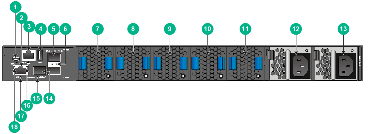
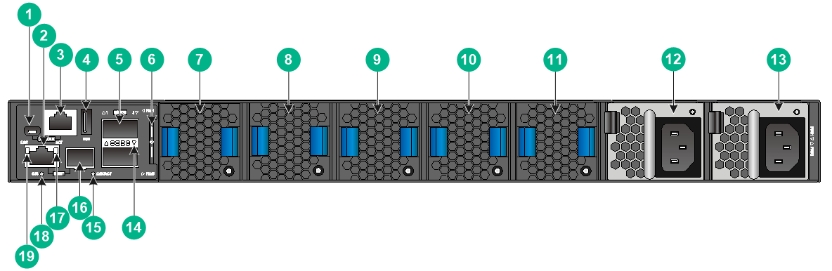
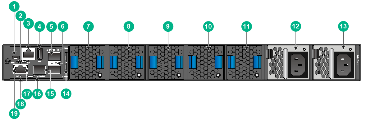
Figure2-2 S6850-56HF rear panel
|
(1) Mini USB console port |
(2) Copper management Ethernet port |
|
(3) Serial console port |
(4) USB port |
|
(5) SFP port |
(6) SFP port LED |
|
(7) Fan tray 1 |
(8) Fan tray 2 |
|
(9) Fan tray 3 |
(10) Fan tray 4 |
|
(11) Fan tray 5 |
(12) Power module 1 |
|
(13) Power module 2 |
(14) Fiber management Ethernet port |
|
(15) Fiber Management Ethernet port LED (LINK/ACT) |
|
|
(16) Copper management Ethernet port LED (ACT) |
(17) System status LED (SYS) |
|
(18) Copper management Ethernet port LED (LINK) |
|
The S6850-56HF switch comes with power module slot PWR1 empty and power module slot PWR2 installed with a filler panel. You can install one or two power modules for the switch as needed. In Figure2-2, two LSVM1AC650 power modules are installed in the power module slots.
The S6850-56HF switch comes with the five fan tray slots empty. You must install five fan trays of the same model for the switch. In Figure2-2, five LSWM1FANSA fan trays are installed in the fan tray slots.
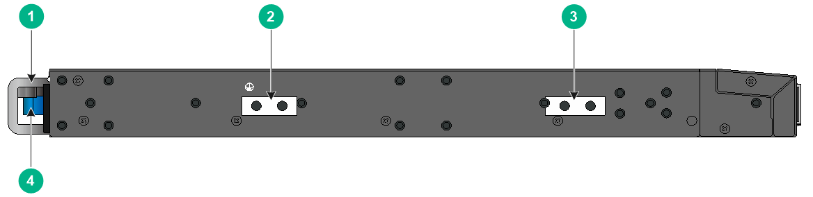
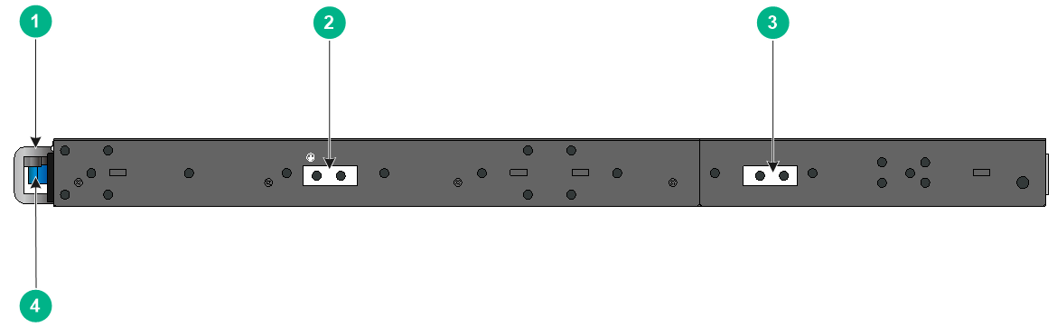
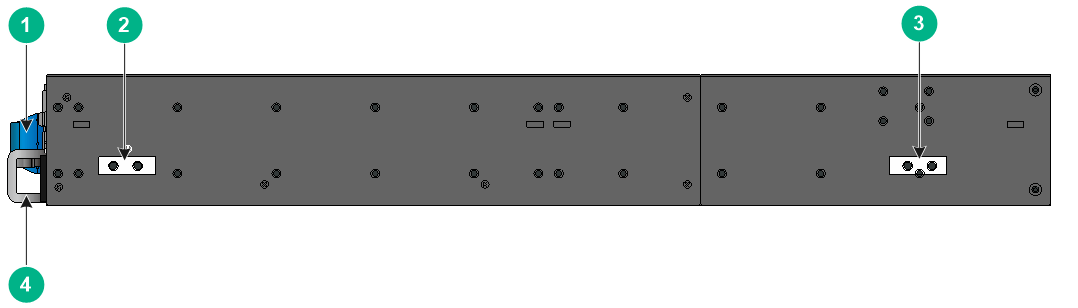
Figure2-3 S6850-56HF left panel
|
(1) Power module handle |
(2) Primary grounding point |
|
(3) Auxiliary grounding point |
(4) Fan tray handle |
S6850-2C
Figure2-4 S6850-2C front panel

|
(1) Expansion module 1 |
(2) Expansion module 2 |
|
(1) Mini USB console port |
(2) Copper management Ethernet port |
|
(3) Serial console port |
(4) USB port |
|
(5) QSFP28 port |
(6) Serial label pull tab |
|
(7) Fan tray 1 |
(8) Fan tray 2 |
|
(9) Fan tray 3 |
(10) Fan tray 4 |
|
(11) Fan tray 5 |
(12) Power module 1 |
|
(13) Power module 2 |
(14) QSFP28 port LED |
|
(15) Fiber management Ethernet port LED (LINK/ACT) |
|
|
(16) Fiber management Ethernet port |
(17) Copper management Ethernet port LED (ACT) |
|
(18) System status LED (SYS) |
(19) Copper management Ethernet port LED (LINK) |
The ESN serial number and MAC address of the S6850-2C switch can be found on the serial label pull tab.
The S6850-2C switch comes with expansion slot 1 empty and expansion slot 2 installed with a filler panel. You can install one or two expansion modules for the switch as needed. In Figure2-4, two LSWM18CQ interface modules are installed in the expansion slots.
The S6850-2C switch comes with power module slot PWR1 empty and power module slot PWR2 installed with a filler panel. You can install one or two power modules for the switch as needed. In Figure2-5, two LSVM1AC650 power modules are installed in the power module slots.
The S6850-2C switch comes with the five fan tray slots empty. You must install five fan trays of the same model for the switch. In Figure2-5, five LSWM1FANSA fan trays are installed in the fan tray slots.
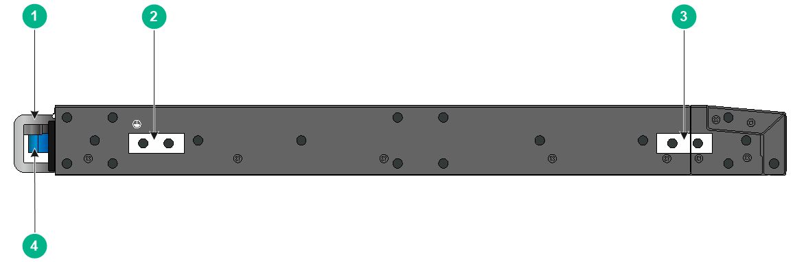
Figure2-6 S6850-2C left panel
|
(1) Power module handle |
(2) Primary grounding point |
|
(3) Auxiliary grounding point |
(4) Fan tray handle |
S9850-4C
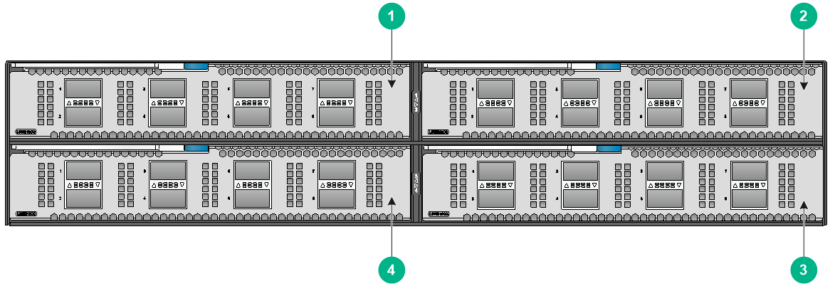
Figure2-7 S9850-4C front panel
|
(1) Expansion module 1 |
(2) Expansion module 2 |
|
(3) Expansion module 4 |
(4) Expansion module 3 |
|
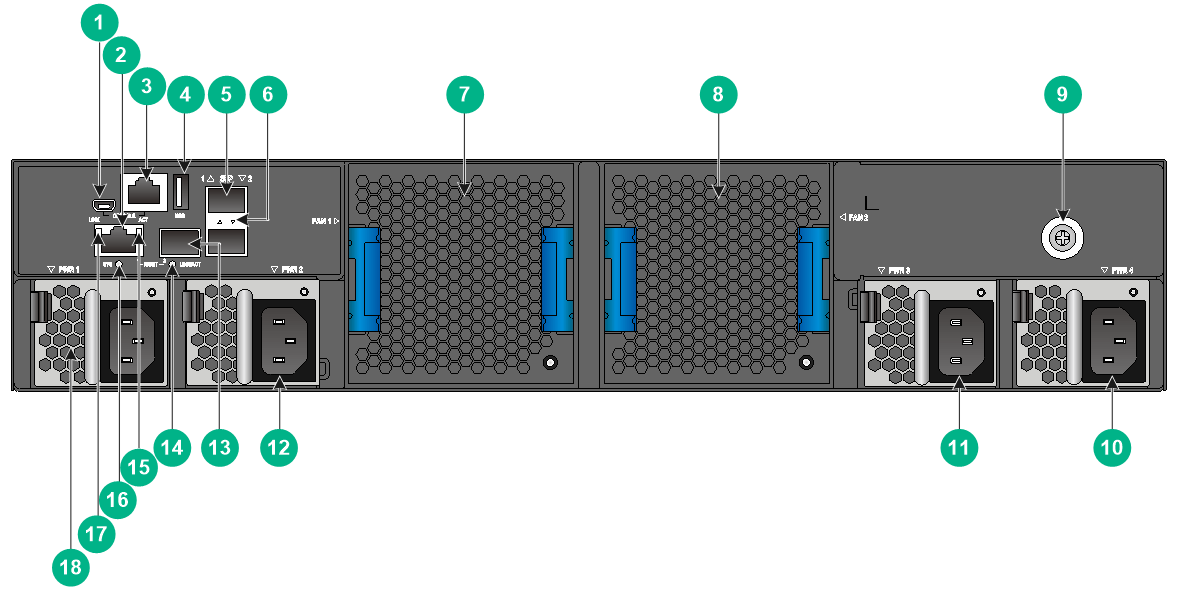
(1) Mini USB console port |
(2) Copper management Ethernet port |
|
(3) Serial console port |
(4) USB port |
|
(5) SFP port |
(6) SFP port LED |
|
(7) Fan tray 1 |
(8) Fan tray 2 |
|
(9) Grounding screw (auxiliary grounding point 2) |
(10) Power module 4 |
|
(11) Power module 3 |
(12) Power module 2 |
|
(13) Fiber management Ethernet port |
|
|
(14) Fiber management Ethernet port LED (LINK/ACT) |
|
|
(15) Copper management Ethernet port LED (ACT) |
(16) System status LED (SYS) |
|
(17) Copper management Ethernet port LED (LINK) |
(18) Power module 1 |
The S9850-4C switch comes with expansion slot 1 empty and the other three expansion slots each installed with a filler panel. You can install one to four expansion modules for the switch as needed. In Figure2-7, four LSWM18CQ interface modules are installed in the expansion slots.
The S9850-4C switch comes with power module slots PWR2 and PWR3 empty and the other two power module slots each installed with a filler panel. You can install two to four power modules for the switch as needed. In Figure2-8, four LSVM1AC650 power modules are installed in the power module slots.
The S9850-4C switch comes with the two fan tray slots empty. You must install two fan trays of the same model for the switch. In Figure2-8, two LSWM1BFANSC fan trays are installed in the fan tray slots.
Figure2-9 S9850-4C left panel
|
(1) Fan tray handle |
(2) Primary grounding point |
|
(3) Auxiliary grounding point 1 |
(4) Power module handle |
S9850-32H
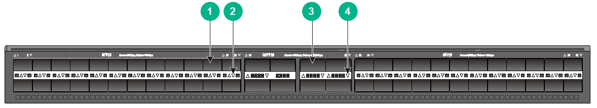
Figure2-10 S9850-32H front panel
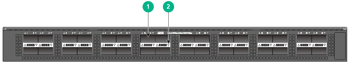
|
(1) QSFP28 port |
(2) QSFP28 port LED |
Figure2-11 S9850-32H rear panel
|
(1) Mini USB console port |
(2) Copper management Ethernet port |
|
(3) Serial console port |
(4) USB port |
|
(5) SFP port |
(6) SFP port LED |
|
(7) Fan tray 1 |
(8) Fan tray 2 |
|
(9) Fan tray 3 |
(10) Fan tray 4 |
|
(11) Fan tray 5 |
(12) Power module 1 |
|
(13) Power module 2 |
(14) Serial label pull tab |
|
(15) Fiber management Ethernet port |
|
|
(16) Fiber management Ethernet port LED (LINK/ACT) |
|
|
(17) Copper management Ethernet port LED (ACT) |
|
|
(18) System status LED (SYS) |
(19) Copper management Ethernet port LED (LINK) |
The ESN serial number and MAC address of the S9850-32H switch can be found on the serial label pull tab.
The S9850-32H switch comes with power module slot PWR1 empty and power module slot PWR2 installed with a filler panel. You can install one or two power modules for the switch as needed. In Figure2-11, two LSVM1AC650 power modules are installed in the power module slots.
The S9850-32H switch comes with the five fan tray slots empty. You must install five fan trays of the same model for the switch. In Figure2-11, five LSWM1FANSA fan trays are installed in the fan tray slots.
Figure2-12 S9850-32H left panel
|
(1) Fan tray handle |
(2) Primary grounding point |
|
(3) Auxiliary grounding point |
(4) Power module handle |
3 FRUs
|
|
CAUTION: Do not install fan trays of different models on the same switch. |
The switch uses modular design. Table3-1 describes the FRUs available for the switch.
Table3-1 FRUs available for the switch
|
FRUs |
BOM code |
S6850-56HF |
S6850-2C |
S9850-4C |
S9850-32H |
|
Power modules |
|||||
|
LSVM1AC650 |
0231A0QM |
Yes |
Yes |
Yes |
Yes |
|
LSVM1DC650 |
0231A0QP |
Yes |
Yes |
Yes |
Yes |
|
Fan trays |
|||||
|
LSWM1FANSA |
0231A4BB |
Yes |
Yes |
No |
Yes |
|
LSWM1FANSA-SN (support electronic label information reading) |
0231AG9L |
Yes. · LS-6850-56HF: in Release 6607 and later versions and R6555P01 installed with the R6555P01H31 patch. · LS-6850-56HF-H1: in F6623 and later versions. |
Yes, in Release 6607 and later versions and R6555P01 installed with the R6555P01H31 patch. |
No |
Yes, in Release 6607 and later versions and R6555P01 installed with the R6555P01H31 patch. |
|
LSWM1FANSAB |
0231A4BC |
Yes |
Yes |
No |
Yes |
|
LSWM1FANSAB-SN (support electronic label information reading) |
0231AG9H |
Yes. · LS-6850-56HF: in Release 6607 and later versions and R6555P01 installed with the R6555P01H31 patch. · LS-6850-56HF-H1: in F6623 and later versions. |
Yes, in Release 6607 and later versions and R6555P01 installed with the R6555P01H31 patch. |
No |
Yes, in Release 6607 and later versions and R6555P01 installed with the R6555P01H31 patch. |
|
LSWM1BFANSC |
0231A2Y7 |
No |
No |
Yes |
No |
|
LSWM1BFANSC-SN (support electronic label information reading) |
0231AG9G |
No |
No |
Yes, in Release 6555P01 and later versions. |
No |
|
LSWM1BFANSCB |
0231A2Y6 |
No |
No |
Yes |
No |
|
LSWM1BFANSCB-SN (support electronic label information reading) |
0231AG9K |
No |
No |
Yes, in Release 6555P01 and later versions. |
No |
|
Expansion modules |
|||||
|
LSWM18CQ |
0231A4XH |
No |
Yes |
Yes |
No |
|
LSWM18CQMSEC |
0231A8FM |
No |
Yes |
Yes |
No |
|
LSWM116Q |
0231A4XJ |
No |
Yes |
Yes |
No |
|
LSWM18QC |
0231A2U4 |
No |
Yes |
Yes |
No |
|
LSWM124XG2Q |
0231A2U5 |
No |
Yes |
Yes |
No |
|
LSWM124XGT2Q |
0231A2U6 |
No |
Yes |
Yes |
No |
|
LSWM124XG2QFC |
0231A2YE |
No |
Yes |
Yes |
No |
|
LSWM124XG2QL |
0231A2U7 |
No |
Yes |
Yes |
No |
|
LSWM124TG2H |
0231A5S8 |
No |
Yes |
Yes |
No |
|
LSWM116FC |
0231A5SB |
No |
Yes |
Yes |
No |
The S6850-56HF, S6850-2C, and S9850-32H switches can operate correctly with only one power module. You can install two power modules for 1+1 redundancy.
The S9850-4C switch can operate correctly with two power modules. You can install three power modules for 2+1 redundancy or four power modules for 2+2 redundancy.
To ensure heat dissipation, make sure all fan tray slots on the switch have fan trays installed and the fan trays are the same model.
For the support of expansion modules in different software versions, see the release notes.
Power modules
|
|
CAUTION: When the switch has power modules in redundancy, you can replace a power module without powering off the switch. Make sure the power module to be replaced is powered off before you replace it. |
Table3-2 Power module specifications
|
Power module model |
Specifications |
Remarks |
|
LSVM1AC650 |
· Rated input voltage: 100 VAC to 240 VAC @ 50 Hz or 60 Hz · Max input voltage: 90 VAC to 264 VAC @ 47 Hz to 63 Hz · Max output power: 650 W · Melting current of power module fuse: 10 A, 250 V |
For more information about the power modules, see H3C LSVM1AC650 & LSVM1DC650 Power Modules User Manual. |
|
LSVM1DC650 |
· Rated input voltage: –40 VDC to –60 VDC · Max input voltage: –40 VDC to –72 VDC · Max output power: 650 W · Melting current of power module fuse: 30 A, 250 V |
Fan trays
Table3-3 Fan tray specifications
|
Fan tray model |
Item |
Specifications |
|
· LSWM1FANSA/LSWM1FANSA-SN (from the power module side to the port side) · LSWM1FANSAB/LSWM1FANSAB-SN (from the port side to the power module side) |
Dimensions |
40.6 × 42.5 × 118.7 mm (1.60 × 1.67 × 4.67 in) |
|
Fan speed |
21000 R.P.M |
|
|
Max airflow |
35 CFM (0.99 m3/min) |
|
|
Input voltage |
12 V |
|
|
Maximum power consumption |
30 W |
|
|
Documentation reference |
H3C LSWM1FANSA & LSWM1FANSAB Fan Tray User Guide H3C LSWM1FANSA-SN & LSWM1FANSAB-SN Fan Trays User Guide |
|
|
· LSWM1BFANSC/LSWM1BFANSC-SN (from the power module side to the port side) · LSWM1BFANSCB/LSWM1BFANSCB-SN (from the port side to the power module side) |
Dimensions |
80 × 80 × 76 mm (3.15 × 3.15 × 2.99 in) |
|
Fan speed |
13300 R.P.M |
|
|
Max airflow |
120 CFM (3.40 m3/min) |
|
|
Input voltage |
12 V |
|
|
Maximum power consumption |
57 W |
|
|
Documentation reference |
H3C LSWM1BFANSC & LSWM1BFANSCB Fan trays User Guide H3C LSWM1BFANSC-SN & LSWM1BFANSCB-SN Fan trays User Guide |
Expansion modules
The S6850-2C switch provides two expansion slots. The S9850-4C switch provides four expansion slots. Select expansion modules for the switch as required.
Table3-4 Interface modules available for the S6850-2C and S9850-4C switches
|
Interface module model |
Description |
Interface number and type |
Transceiver modules available for the ports |
|
LSWM18CQ |
8-port QSFP28 interface module |
8 × QSFP28 ports |
· For the transceiver modules and cables available for the QSFP28 ports, see "QSFP28 port." · For the transceiver modules and cables available for the QSFP+ ports, see "QSFP+ port." · For the transceiver modules and cables available for the SFP28 ports, see "SFP28 port." · For the transceiver modules and cables available for the SFP+ ports, see "SFP+ port." · For the transceiver modules and cables available for the FC interfaces, see "FC interfaces." |
|
LSWM18CQMSEC |
8-port QSFP28 interface module with MACSec |
8 × QSFP28 ports |
|
|
LSWM116Q |
16-port QSFP+ interface module |
16 × QSFP+ ports |
|
|
LSWM18QC |
8-port QSFP+ interface module |
8 × QSFP+ ports |
|
|
LSWM124XG2Q |
24-port SFP+ and 2-port QSFP+ interface module with MACSec |
· 24 × SFP+ ports · 2 × QSFP+ ports |
|
|
LSWM124XGT2Q |
24-port 10GBASE-T and 2-port QSFP+ interface module with MACSec |
· 24 × 10GBASE-T ports · 2 × QSFP+ ports |
|
|
LSWM124XG2QFC |
24-port SFP+ and 2-port QSFP+ interface module with FC |
· 24 × SFP+ ports · 2 × QSFP+ ports |
|
|
LSWM124XG2QL |
24-port SFP+ and 2-port QSFP+ interface module |
· 24 × SFP+ ports · 2 × QSFP+ ports |
|
|
LSWM124TG2H |
24-port SFP28 and 2-port QSFP28 interface module |
· 24 × SFP28 ports · 2 × QSFP28 ports |
|
|
LSWM116FC |
16-port SFP28 interface module with FC |
16 × SFP28 ports |
Table3-5 Interface module specifications
|
Interface module model |
Dimensions (H × W × D) |
Weight |
Minimum power consumption |
Maximum power consumption |
|
LSWM18CQ |
40.1 × 214 × 274 mm (1.58 × 8.43 × 10.79 in) |
2 kg (4.41 lb) |
19 W |
78 W |
|
LSWM18CQMSEC |
40.1 × 214 × 274 mm (1.58 × 8.43 × 10.79 in) |
2 kg (4.41 lb) |
48 W |
93 W |
|
LSWM116Q |
40.1 × 214 × 274 mm (1.58 × 8.43 × 10.79 in) |
2 kg (4.41 lb) |
15 W |
60 W |
|
LSWM18QC |
40.1 × 214 × 274 mm (1.58 × 8.43 × 10.79 in) |
2 kg (4.41 lb) |
15 W |
30 W |
|
LSWM124XG2Q |
40.1 × 214 × 274 mm (1.58 × 8.43 × 10.79 in) |
2 kg (4.41 lb) |
40 W |
60 W |
|
LSWM124XGT2Q |
40.1 × 214 × 274 mm (1.58 × 8.43 × 10.79 in) |
3 kg (6.61 lb) |
40 W |
123 W |
|
LSWM124XG2QFC |
40.1 × 214 × 274 mm (1.58 × 8.43 × 10.79 in) |
2 kg (4.41 lb) |
40 W |
60 W |
|
LSWM124XG2QL |
40.1 × 214 × 274 mm (1.58 × 8.43 × 10.79 in) |
2 kg (4.41 lb) |
20 W |
36 W |
|
LSWM124TG2H |
40.1 × 214 × 274 mm (1.58 × 8.43 × 10.79 in) |
2 kg (4.41 lb) |
19 W |
78 W |
|
LSWM116FC |
40.1 × 214 × 274 mm (1.58 × 8.43 × 10.79 in) |
2 kg (4.41 lb) |
15 W |
60 W |
|
|
NOTE: Expansion module dimensions are expressed in the Height (H) × Width (W) × Depth (D) format: · H—Height of the front panel of the expansion module. · W—Width of the front panel of the expansion module. · D—Depth from the front panel to the back of the expansion module. (The depth excludes the ejector levers.) |
4 Ports and LEDs
As a best practice, use H3C transceiver modules and cables for the switch. H3C transceiver modules and cables are subject to change over time. For the most up-to-date list of H3C transceiver modules and cables, contact H3C Support or marketing staff. For information about the specifications and views of H3C transceiver modules and cables, see H3C Transceiver Modules User Guide.
Ports
Console port
The switch has two console ports: one serial console port and one mini USB console port.
Table4-1 Console port specifications
|
Item |
Console port |
Mini USB console port |
|
Connector type |
RJ-45 |
USB mini-Type B |
|
Compliant standard |
EIA/TIA-232 |
USB 2.0 |
|
Transmission baud rate |
9600 bps (default) to 115200 bps |
|
|
Services |
· Provides connection to an ASCII terminal. · Provides connection to the serial port of a local PC running terminal emulation program. |
· Provides connection to an ASCII terminal. · Provides connection to the USB port of a local PC running terminal emulation program. |
Management Ethernet port
The switch has two management Ethernet ports: one copper management port and one SFP management port. You can connect the ports to a local PC for software loading and debugging or to a remote management station for remote management.
Table4-2 Management Ethernet port specifications
|
Item |
Specification |
|
Connector type |
· 10/100/1000BASE-T management port: RJ-45. · SFP management port: LC. |
|
Port transmission rate |
· 10/100/1000BASE-T management port: ¡ 10/100 Mbps, half/full duplex, MDI/MDI-X auto-sensing. ¡ 1000 Mbps, full duplex, MDI/MDI-X auto-sensing. · SFP management port: 1000/100 Mbps, full duplex. |
|
Transmission medium and max transmission distance |
· 10/100/1000BASE-T management port: 100 m (328.08 ft) over category-5 UTP cable. · SFP management port: See 100-Megabit transceiver modules in Table4-3 and Gigabit transceiver modules in Table4-4. |
|
Functions and services |
Software upgrade and network management. |
FE SFP modules
Table4-3 FE SFP transceiver modules
|
FE SFP transceiver module |
Central wavelength (nm) |
Connector |
Fiber type and diameter (µm) |
Max transmission distance |
|
SFP-FE-SX-MM1310-A |
1310 |
LC |
Multi-mode, 50/125 |
2 km (1.24 miles) |
|
Multi-mode, 62.5/125 |
||||
|
SFP-FE-LX-SM1310-A |
1310 |
LC |
Single-mode, 9/125 |
15 km (9.32 miles) |
|
SFP-FE-LH40-SM1310 |
1310 |
LC |
Single-mode, 9/125 |
40 km (24.86 miles) |
USB port
The switch has one OHCI-compliant USB 2.0 port that can upload and download data at a rate up to 480 Mbps. You can use this USB port to access the file system on the Flash of the switch, for example, to upload or download application and configuration files.
The USB port supplies power as per USB 2.0 specifications. Use only USB 2.0-compliant USB devices for the USB port. The port might not identity USB devices that are not compliant with USB 2.0.
|
|
NOTE: USB devices from different vendors vary in compatibilities and drivers. H3C does not guarantee correct operation of USB devices from other vendors on the switch. If a USB device fails to operate on the switch, replace it with one from another vendor. |
SFP port
The S6850-56HF, S6850-32H, and S9850-4C switches each provide two SFP ports on the rear panel. You can install FE SFP transceiver modules in Table4-3 and GE SFP transceiver modules in Table4-4 in the SFP ports as needed.
Table4-4 GE SFP transceiver modules available for the SFP ports
|
GE SFP transceiver module |
Central wavelength (nm) |
Connector |
Cable/Fiber type and diameter (µm) |
Modal bandwidth (MHz × km) |
Max transmission distance |
|
SFP-GE-T SFP-GE-T-D |
N/A |
RJ-45 |
Twisted pair cable |
N/A |
100 m (328.08 ft) |
|
SFP-GE-SX-MM850-A SFP-GE-SX-MM850-D |
850 |
LC |
Multi-mode, 50/125 |
500 |
550 m (1804.46 ft) |
|
400 |
500 m (1640.42 ft) |
||||
|
Multi-mode, 62.5/125 |
200 |
275 m (902.23 ft) |
|||
|
160 |
200 m (656.17 ft) |
||||
|
SFP-GE-LX-SM1310-A |
1310 |
LC |
Single-mode, 9/125 |
N/A |
10 km (6.21 miles) |
|
Multi-mode, 50/125 |
500 or 400 |
550 m (1804.46 ft) |
|||
|
Multi-mode, 62.5/125 |
500 |
550 m (1804.46 ft) |
|||
|
SFP-GE-LX-SM1310-D |
1310 |
LC |
Single-mode, 9/125 |
N/A |
10 km (6.21 miles) |
|
SFP-GE-LH40-SM1310 SFP-GE-LH40-SM1310-D |
1310 |
LC |
Single-mode, 9/125 |
N/A |
40 km (24.86 miles) |
|
SFP-GE-LH40-SM1550 |
1550 |
LC |
Single-mode, 9/125 |
N/A |
40 km (24.86 miles) |
|
SFP-GE-LH80-SM1550 SFP-GE-LH80-SM1550-D |
1550 |
LC |
Single-mode, 9/125 |
N/A |
80 km (49.71 miles) |
|
SFP-GE-LH100-SM1550 |
1550 |
LC |
Single-mode, 9/125 |
N/A |
100 km (62.14 miles) |
Installed with an SFP-GE-T or SFP-GE-T-D transceiver module, an SFP port can operate only at 1 Gbps.
QSFP28 port
Table4-5 describes the switches and interface modules that provide QSFP28 ports.
Table4-5 Switches and interface modules that provide QSFP28 ports
|
Switches and interface modules that provide QSFP28 ports |
Number of QSFP28 ports |
|
S6850-56HF switch |
8 |
|
S6850-2C switch |
2 |
|
S9850-32H switch |
32 |
|
LSWM18CQ interface module |
8 |
|
LSWM124TG2H interface module |
2 |
|
LSWM18CQMSEC interface module |
8 |
You can install the following transceiver modules and cables in the QSFP28 ports:
· QSFP28 transceiver modules in Table4-6.
· QSFP28 copper cables in Table4-7.
· QSFP28 fiber cables in Table4-8.
· QSFP28 to SFP28 copper cables in Table4-9.
· QSFP+ transceiver modules in Table4-10.
· QSFP+ copper cables in Table4-11.
· QSFP+ fiber cables in Table4-12.
· QSFP+ to SFP+ copper cables in Table4-13.
With a QSFP+ to SFP+ adapter installed in a QSFP28 port, the QSFP28 port supports SFP+ transceiver modules listed in Table4-17. Before using a QSFP+ to SFP+ adapter, execute the using tengige command on the QSFP28 port where the adapter is to be installed.
|
|
IMPORTANT: The QSFP+ to SFP+ adapter is available only in R6555 and later versions. |
|
|
NOTE: · You can use a QSFP-40G-SR4-MM850 or QSFP-40G-CSR4-MM850 transceiver module to connect a QSFP+ port to four SFP+ ports. The QSFP+ transceiver module and SFP+ transceiver modules to be connected must be the same in specifications, including central wavelength and fiber type. · Interface numbered 31 on the S6850-56HF switch cannot be split into four interfaces. · The interface numbered 31 on an S9850-32H switch cannot be split by default. To split this interface, first enable the hardware resource flex mode for the device by using the hardware-resource flex-mode enable command. For more information about the hardware resource flex mode, see device management configuration in H3C S6805 & S6825 & S6850 & S9850 Switch Series Fundamentals Configuration Guide. Only F6633 and later versions support port splitting of the interface numbered 31 on an S9850-32H switch. · When the LSWM18CQ or LSWM18CQMSEC interface module is installed in slot 2 on the S9850-4C switch, interface numbered 7 on the interface module cannot be split into four interfaces. · When the LSWM124TG2H interface module is installed in slot 2 on the S9850-4C switch, the interface numbered 25 on the interface module cannot be split into four interfaces. |
Table4-6 QSFP28 transceiver modules available for the QSFP28 ports
|
QSFP28 transceiver module |
Central wavelength (nm) |
Connector |
Fiber type and diameter (µm) |
Modal bandwidth (MHz*km) |
Maximum transmission distance |
|
QSFP-100G-SR4-MM850 |
850 |
MPO (PC polished, 12-fiber) |
Multi-mode, 50/125 |
2000 |
70 m (229.66 ft) |
|
4700 |
100 m (328.08 ft) |
||||
|
QSFP-100G-BIDI-MM850 (end of sale) |
Two lanes: · 855 · 908 |
LC |
Multi-mode, 50/125 |
2000 |
70 m (229.66 ft) |
|
4700 |
100 m (328.08 ft) |
||||
|
QSFP-100G-eSR4-MM850 |
850 |
MPO (PC polished, 12-fiber) |
Multi-mode, 50/125 |
4700 |
300 m (984.25 ft) |
|
QSFP-100G-PSM4-SM1310 |
1295 to 1325 |
MPO (APC polished, 12-fiber) |
Single-mode, 9/125 |
N/A |
500 m (1640.42 ft) |
|
QSFP-100G-LR4-WDM1300 QSFP-100G-LR4-WDM1300-A |
Four lanes: · 1295.56 · 1300.05 · 1304.58 · 1309.14 |
LC |
Single-mode, 9/125 |
N/A |
10 km (6.21 miles) |
|
QSFP-100G-LR4L-WDM1300 |
Four lanes: · 1271 · 1291 · 1311 · 1331 |
LC |
Single-mode, 9/125 |
N/A |
2 km (1.24 miles) |
|
QSFP-100G-SWDM4-MM850 |
Four lanes: · 850 · 880 · 910 · 940 |
LC |
Multi-mode, 50/125 |
2000 |
75 m (246.06 ft) |
|
4700 |
100 m (328.08 ft) |
||||
|
QSFP-100G-ER4L-WDM1300 |
Four lanes: · 1295.56 · 1300.05 · 1304.58 · 1309.14 |
LC |
Single-mode, 9/125 |
N/A |
40 km (24.86 miles) |
|
QSFP-100G-CWDM4-SM1300-A |
Four lanes: · 1271 · 1291 · 1311 · 1331 |
LC |
Single-mode, 9/125 |
N/A |
2 km (1.24 miles) |
|
|
IMPORTANT: · QSFP-100G-SWDM4-MM850 and QSFP-100G-eSR4-MM850 are available only in E6553 and later versions. · QSFP-100G-BIDI-MM850 is available only in R6606 and later versions and R6555P02. · QSFP-100G-ER4L-WDM1300 is available only in R6607 and later versions. |
Table4-7 QSFP28 copper cables available for the QSFP28 ports
|
QSFP28 copper cable |
Cable length |
|
QSFP-100G-D-CAB-1M |
1 m (3.28 ft) |
|
QSFP-100G-D-CAB-3M |
3 m (9.84 ft) |
|
QSFP-100G-D-CAB-5M |
5 m (16.40 ft) |
Table4-8 QSFP28 fiber cables available for the QSFP28 ports
|
QSFP28 fiber cable |
Cable length |
|
QSFP-100G-D-AOC-7M |
7 m (22.97 ft) |
|
QSFP-100G-D-AOC-10M |
10 m (32.81 ft) |
|
QSFP-100G-D-AOC-20M |
20 m (65.62 ft) |
Table4-9 QSFP28 to SFP28 copper cables available for the QSFP28 ports
|
QSFP28 to SFP28 copper cable |
Cable length |
|
QSFP-100G-4SFP-25G-CAB-1M |
1 m (3.28 ft) |
|
QSFP-100G-4SFP-25G-CAB-3M |
3 m (9.84 ft) |
|
QSFP-100G-4SFP-25G-CAB-5M |
5 m (16.40 ft) |
Table4-10 QSFP+ transceiver modules available for the QSFP28 ports
|
Central wavelength (nm) |
Connector |
Fiber type and diameter (µm) |
Modal bandwidth (MHz × km) |
Max transmission distance |
|
|
QSFP-40G-SR4-MM850 |
850 |
MPO (PC-polished, 12-core) |
Multi-mode, 50/125 |
2000 |
100 m (328.08 ft) |
|
4700 |
150 m (492.13 ft) |
||||
|
QSFP-40G-CSR4-MM850 |
850 |
MPO (PC-polished, 12-core) |
Multi-mode, 50/125 |
2000 |
300 m (984.25 ft) |
|
4700 |
400 m (1312.33 ft) |
||||
|
QSFP-40G-LR4-PSM1310 |
1310 |
MPO (APC-polished, 12-core) |
Single-mode, 9/125 |
N/A |
10 km (6.21 miles) |
|
QSFP-40G-BIDI-SR-MM850 |
850 |
LC |
Multi-mode, 50/125 |
2000 |
100 m (328.08 ft) |
|
4700 |
150 m (492.13 ft) |
||||
|
QSFP-40G-BIDI-WDM850 |
Four lanes: · 850 · 880 · 910 · 940 |
LC |
Multi-mode, 50/125 |
2000 |
240 m (787.40 ft) |
|
4700 |
350 m (1148.29 ft) |
||||
|
QSFP-40G-ER4-WDM1300 |
Four lanes: · 1271 · 1291 · 1311 · 1331 |
LC |
Single-mode, 9/125 |
N/A |
40 km (24.86 miles) |
|
QSFP-40G-LR4-WDM1300 |
Four lanes: · 1271 · 1291 · 1311 · 1331 |
LC |
Single-mode, 9/125 |
N/A |
10 km (6.21 miles) |
|
QSFP-40G-LR4L-WDM1300 |
Four lanes: · 1271 · 1291 · 1311 · 1331 |
LC |
Single-mode, 9/125 |
N/A |
2 km (1.24 miles) |
Table4-11 QSFP+ copper cables available for the QSFP28 ports
|
QSFP+ copper cable |
Max transmission distance |
|
LSWM1QSTK0 |
1 m (3.28 ft) |
|
LSWM1QSTK1 |
3 m (9.84 ft) |
|
LSWM1QSTK2 |
5 m (16.40 ft) |
Table4-12 QSFP+ fiber cables available for the QSFP28 ports
|
QSFP+ fiber cable |
Cable length |
|
QSFP-40G-D-AOC-3M |
3 m (9.84 ft) |
|
QSFP-40G-D-AOC-7M |
7 m (22.97 ft) |
|
QSFP-40G-D-AOC-10M |
10 m (32.81 ft) |
|
QSFP-40G-D-AOC-20M |
20 m (65.62 ft) |
Table4-13 QSFP+ to SFP+ copper cables available for the QSFP28 ports
|
QSFP+ to SFP+ copper cable |
Max transmission distance |
|
LSWM1QSTK3 |
1 m (3.28 ft) |
|
LSWM1QSTK4 |
3 m (9.84 ft) |
|
LSWM1QSTK5 |
5 m (16.40 ft) |
|
|
IMPORTANT: · QSFP-40G-ER4-WDM1300 is available only in E6553 and later versions. · QSFP-40G-BIDI-WDM850 is available only in R6607 and later versions. |
|
|
NOTE: MPO connectors include physical contact (PC) connectors with a flat-polished face and angle-polished contact (APC) connectors with an angle-polished face (8°). |
QSFP+ port
The LSWM116Q and LSWM18QC interface modules provide 16 and 8 QSFP+ ports, respectively. The LSWM124XG2Q, LSWM124XG2QFC, LSWM124XG2QL, and LSWM124XGT2Q interface modules each provide two QSFP+ ports. You can install the following transceiver modules and cables in the QSFP+ ports:
· QSFP+ transceiver modules in Table4-10.
· QSFP+ copper cables in Table4-11.
· QSFP+ fiber cables in Table4-12.
· QSFP+ to SFP+ copper cables in Table4-13.
With a QSFP+ to SFP+ adapter installed in a QSFP+ port, the QSFP+ port supports SFP+ transceiver modules listed in Table4-17. Before using a QSFP+ to SFP+ adapter, execute the using tengige command on the QSFP+ port where the adapter is to be installed.
|
|
IMPORTANT: The QSFP+ to SFP+ adapter is available only in R6555 and later versions. |
|
|
NOTE: · QSFP+ ports on the LSWM116Q interface module cannot be split into four interfaces. · When you install the LSWM18QC interface module in slot 2 on the S9850-4C switch, interface numbered 8 on the interface module cannot be split into four interfaces. · When you install the LSWM124XG2Q, LSWM124XG2QFC, LSWM124XG2QL, or LSWM124XGT2Q interface module in slot 2 on the S9850-4C switch, interface numbered 25 cannot be split into four interfaces. |
SFP28 port
The S6850-56HF switch provides 48 SFP28 ports. The LSWM124TG2H provides 24 SFP28 ports. The LSWM116FC provides 16 SFP28 ports. The S6850-56HF switch supports the following transceiver modules and cables:
· SFP28 transceiver modules in Table4-14.
· SFP28 copper cables in Table4-15.
· SFP28 fiber cables in Table4-16.
· 10-GE SFP+ transceiver modules in Table4-17.
· 10-GE SFP+ copper cables in Table4-18.
· 10-GE SFP+ fiber cables in Table4-19.
· GE SFP transceiver modules in Table4-4.
|
|
IMPORTANT: · To use an SFP28 or SFP+ copper cable to connect an SFP28 port on an S6850-56HF switch to a peer port that does not support speed and duplex autonegotiation, you must configure the same duplex mode and speed for the two ports. The speed must be the same as that of the transceiver module installed in the port. · The SFP28 ports on an LSWM124TG2H interface module do not support speed and duplex autonegotiation. To use an SFP+ transceiver module, SFP+ cable, or SFP transceiver module to connect an SFP28 port on an LSWM124TG2H interface module to a peer port, you must configure the same duplex mode and speed for the two ports. The speed must be the same as that of the transceiver module installed in the port. · To use an SFP transceiver module except for an SFP-GE-T or SFP-GE-T-D transceiver module, make sure the autonegotiation feature is disabled on the peer port. · For more information about SFP28 port configurations, see Ethernet interface configuration in H3C S6805 & S6825 & S6850 & S9850 Switch Series Layer 2—LAN Switching Configuration Guide. · LSWM124TG2H interface modules do not support SFP-25G-LR-SM1310 transceiver modules. LSWM116FC interface modules only support SFP-25G-LR-SM1310 transceiver modules. · When an interface on the LSWM116FC acts as an Ethernet interface, it can only operate at 25 Gbps in full duplex mode and does not support speed and duplex autonegotiation. |
|
|
CAUTION: The S6850-56HF switch supports a maximum of eight long-haul SFP+ transceiver modules. If you install LSWM124TG2H interface modules on the S6850-2C or S9850-4C switch, each interface module supports a maximum of eight long-haul SFP+ transceiver modules. The available long-haul SFP+ transceiver module models are as follows: · SFP-XG-LH40-SM1550. · SFP-XG-LH40-SM1550-D. · SFP-XG-LH80-SM1550. · SFP-XG-LH80-SM1550-D. |
Table4-14 SFP28 transceiver modules available for the SFP28 ports
|
SFP28 transceiver module |
Central wavelength (nm) |
Connector |
Fiber type and diameter (µm) |
Modal bandwidth (MHz*km) |
Maximum transmission distance |
|
SFP-25G-SR-MM850 |
850 |
LC |
Multi-mode, 50/125 |
2000 |
· FEC negotiation disabled: 30 m (98.43 ft) · FEC negotiation enabled: 70 (229.66 ft) |
|
4700 |
· FEC negotiation disabled: 40 m (131.23 ft) · FEC negotiation enabled: 100 m (328.08 ft) |
||||
|
SFP-25G-LR-SM1310 |
1310 |
LC |
Single-mode, 9/125 |
N/A |
10 km (6.21 miles) |
|
|
NOTE: For more information about FEC negotiation, see Ethernet interface configuration in H3C S6805 & S6825 & S6850 & S9850 Switch Series Layer 2—LAN Switching Configuration Guide. |
Table4-15 25G SFP28 copper cables available for the SFP28 ports
|
25G SFP28 copper cable |
Max transmission distance |
|
SFP-25G-D-CAB-1M |
1 m (3.28 ft) |
|
SFP-25G-D-CAB-3M |
3 m (9.84 ft) |
|
SFP-25G-D-CAB-5M |
5 m (16.40 ft) |
Table4-16 25G SFP28 fiber cables available for the SFP28 ports
|
25G SFP28 fiber cable |
Max transmission distance |
|
SFP-25G-D-AOC-3M |
3 m (9.84 ft) |
|
SFP-25G-D-AOC-5M |
5 m (16.40 ft) |
|
SFP-25G-D-AOC-7M |
7 m (22.97 ft) |
|
SFP-25G-D-AOC-10M |
10 m (32.81 ft) |
|
SFP-25G-D-AOC-20M |
20 m (65.62 ft) |
|
|
IMPORTANT: · SFP-25G-LR-SM1310 is available only in R6555P01 and later versions. · SFP28 fiber cables are available only in E6553 and later versions. |
Table4-17 10-GE SFP+ transceiver modules available for the SFP28 ports
|
10-GE SFP+ transceiver module |
Central wavelength (nm) |
Connector |
Fiber type and diameter (µm) |
Modal bandwidth (MHz × km) |
Max transmission distance |
|
SFP-XG-SX-MM850-A |
850 |
LC |
Multi-mode, 50/125 |
2000 |
300 m (984.25 ft) |
|
500 |
82 m (269.03 ft) |
||||
|
400 |
66 m (216.54 ft) |
||||
|
Multi-mode, 62.5/125 |
200 |
33 m (108.27 ft) |
|||
|
160 |
26 m (85.30 ft) |
||||
|
SFP-XG-LX-SM1310 |
1310 |
LC |
Single-mode, 9/125 |
N/A |
10 km (6.21 miles) |
|
SFP-XG-LH40-SM1550 SFP-XG-LH40-SM1550-D |
1550 |
LC |
Single-mode, 9/125 |
N/A |
40 km (24.86 miles) |
|
SFP-XG-LH80-SM1550 SFP-XG-LH80-SM1550-D |
1550 |
LC |
Single-mode, 9/125 |
N/A |
80 km (49.71 miles) |
|
SFP-XG-LX-SM1270-BIDI |
· TX: 1270 · RX: 1330 |
LC |
Single-mode, 9/125 |
N/A |
10 km (6.21 miles) |
|
SFP-XG-LX-SM1330-BIDI |
· TX: 1330 · RX: 1270 |
LC |
Single-mode, 9/125 |
N/A |
10 km (6.21 miles) |
|
SFP-XG-LH40-SM1270-BIDI |
· TX: 1270 · RX: 1330 |
LC |
Single-mode, 9/125 |
N/A |
40 km (24.86 miles) |
|
SFP-XG-LH40-SM1330-BIDI |
· TX: 1330 · RX: 1270 |
LC |
Single-mode, 9/125 |
N/A |
40 km (24.86 miles) |
|
SFP-XG-LH80-SM1490-BIDI |
· TX: 1490 · RX: 1550 |
LC |
Single-mode, 9/125 |
N/A |
80 km (49.71 miles) |
|
SFP-XG-LH80-SM1550-BIDI |
· TX: 1550 · RX: 1490 |
LC |
Single-mode, 9/125 |
N/A |
80 km (49.71 miles) |
Table4-18 10-GE SFP+ copper cables available for the SFP28 ports
|
10-GE SFP+ copper cable |
Max transmission distance |
|
LSWM1STK |
0.65 m (2.13 ft) |
|
LSWM2STK |
1.2 m (3.94 ft) |
|
LSWM3STK |
3 m (9.84 ft) |
|
LSTM1STK |
5 m (16.40 ft) |
Table4-19 10-GE SFP+ fiber cables available for the SFP28 ports
|
10-GE SFP+ fiber cable |
Max transmission distance |
|
SFP-XG-D-AOC-7M |
7 m (22.97 ft) |
|
SFP-XG-D-AOC-10M |
10 m (32.81 ft) |
|
SFP-XG-D-AOC-20M |
20 m (65.62 ft) |
|
|
IMPORTANT: · You must use two BIDI transceiver modules in pairs. For example, if one end uses the SFP-XG-LX-SM1270-BIDI transceiver module, the peer end must use the SFP-XG-LX-SM1330-BIDI transceiver module. · SFP-XG-LH40-SM1550, SFP-XG-LH40-SM1550-D, SFP-XG-LH80-SM1550, and SFP-XG-LH80-SM1550-D transceiver modules are available only in E6553 and later versions. · The SFP-XG-LX-SM1270-BIDI, SFP-XG-LX-SM1330-BIDI, SFP-XG-LH40-SM1270-BIDI, SFP-XG-LH40-SM1330-BIDI, SFP-XG-LH80-SM1490-BIDI, and SFP-XG-LH80-SM1550-BIDI transceiver modules are available only in R6607 and later versions. |
SFP+ port
The LSWM124XG2Q, LSWM124XG2QFC, and LSWM124XG2QL interface modules each provide 24 SFP+ ports. The SFP+ ports support the following transceiver modules and cables:
· 10-GE SFP+ transceiver modules in Table4-17.
· 10-GE SFP+ copper cables in Table4-18.
· 10-GE SFP+ fiber cables in Table4-19.
· GE SFP transceiver modules in Table4-4.
|
|
IMPORTANT: · SFP+ ports on an LSWM124XG2QL interface module do not support rate and duplex autonegotiation. To use a GE SFP transceiver module to connect an SFP+ port on an LSWM124XG2QL interface module to a peer port, you must configure the speed 1000 and duplex full commands on both ports. · To use an SFP transceiver module except for an SFP-GE-T or SFP-GE-T-D transceiver module, make sure the autonegotiation feature is disabled on the peer port. |
FC interfaces
A port on an LSWM116FC interface module can operate as an Ethernet interface or FC interface. When it operates as an FC interface, it supports 8G/16G/32G FC modules. For the transceiver modules available for the FC interfaces, see Table4-20.
The 24 SFP+ ports on an LSWM124XG2QFC can operate as Ethernet interfaces or FC interfaces. When such an SFP+ port operates as an FC interface, it supports 8G FC modules SFP-FC-8G-SW-MM850 and SFP-FC-8G-LW-SM1310.
To change the port type between a Layer 2 Ethernet interface and an FC interface, execute the port-type command in Layer 2 Ethernet interface view. For more information, see FC and FCoE configuration in H3C S6805 & S6825 & S6850 & S9850 Switch Series Configuration Guide.
After an interface on an LSWM116FC interface module is changed to an FC interface, the FC interface can operate at 8 Gbps, 16 Gbps, or 32 Gbps, depending on the speed of the installed transceiver module.
An LSWM116FC interface module has 16 interfaces, and every two neighboring interfaces belong to one port group. If you change an Ethernet interface to an FC interface by using the port-type fc command, the other interface in the same port group is also changed to an FC interface. If you change an FC interface to an Ethernet interface by using the port-type ethernet command, the other interface in the same port group is also changed to an Ethernet interface.
Table4-20 Transceiver modules available for the FC interfaces
|
Module |
Central wavelength (nm) |
Connector |
Fiber type and diameter (µm) |
Modal bandwidth (MHz × km) |
Max transmission distance |
|
SFP-FC-8G-SW-MM850 |
850 |
LC |
Multi-mode, 62.5/125 |
200 |
150 m (492.13 ft) |
|
70 m ( 229.66 ft) |
|||||
|
21 m (68.90 ft) |
|||||
|
Multi-mode, 50/125 |
500 |
300 m (984.25 ft) |
|||
|
150 m (492.13 ft) |
|||||
|
50 m (164.04 ft) |
|||||
|
2000 |
500 m (1640.42 ft) |
||||
|
380 m (1246.72 ft) |
|||||
|
150 m (492.13 ft) |
|||||
|
4700 |
N/A |
||||
|
400 m (1312.34 ft) |
|||||
|
190 m (623.36 ft) |
|||||
|
SFP-FC-8G-LW-SM1310 |
1310 |
LC |
Single-mode, 9/125 |
N/A |
10 km (6.21 miles) |
|
SFP-FC-16G-SW-MM850 |
850 |
LC |
Multi-mode, 62.5/125 |
200 |
70 m (229.66 ft) |
|
21 m (68.90 ft) |
|||||
|
15 m (49.21 ft) |
|||||
|
Multi-mode, 50/125 |
500 |
150 m (492.13 ft) |
|||
|
50 m (164.04 ft) |
|||||
|
35 m (114.83 ft) |
|||||
|
2000 |
380 m (1246.72 ft) |
||||
|
150 m (492.13 ft) |
|||||
|
100 m (328.08 ft) |
|||||
|
4700 |
400 m (1312.34 ft) |
||||
|
190 m (623.36 ft) |
|||||
|
125 m (410.11 ft) |
|||||
|
SFP-FC-16G-LW-SM1310 |
1310 |
LC |
Single-mode, 9/125 |
N/A |
10 km (6.21 miles) |
|
SFP-FC-32G-SW-MM850 |
850 |
LC |
Multi-mode, 62.5/125 |
200 |
21 m (68.90 ft) |
|
15 m (49.21 ft) |
|||||
|
N/A |
|||||
|
Multi-mode, 50/125 |
500 |
50 m (164.04 ft) |
|||
|
35 m (114.83 ft) |
|||||
|
20 m (65.62 ft) |
|||||
|
2000 |
150 m (492.13 ft) |
||||
|
100 m (328.08 ft) |
|||||
|
70 m ( 229.66 ft) |
|||||
|
4700 |
190 m (623.36 ft) |
||||
|
125 m (410.11 ft) |
|||||
|
100 m (328.08 ft) |
LEDs
System status LED
The system status LED shows the operating status of the switch.
Table4-21 System status LED description
|
LED mark |
Status |
Description |
|
SYS |
Steady green |
The switch is operating correctly. |
|
Flashing green |
The switch is performing power-on self test (POST). |
|
|
Steady red |
The system has failed to pass POST or has problems such as fan failure. |
|
|
Flashing blue (3 Hz) |
Helps you to locate the switch. To locate the switch in the rack, execute the locator blink blink-time command. The LED then flashes blue at 3 Hz. |
|
|
Off |
The switch is powered off or has failed to start up. |
QSFP28 port LED
Table4-22 QSFP28 port LED description
|
LED status |
Description |
|
Steady green |
A transceiver module or cable has been correctly installed. The port has a link and is operating at 100 Gbps. |
|
Flashing green |
The port is sending or receiving data at 100 Gbps. |
|
Steady yellow |
A transceiver module or cable has been correctly installed. The port has a link and is operating at 10 Gbps, 25 Gbps, or 40 Gbps. |
|
Flashing yellow (3 Hz) |
The port is sending or receiving data at 10 Gbps, 25 Gbps, or 40 Gbps. |
|
Off |
No transceiver module or cable has been installed or no link is present on the port. |
QSFP+ port LED
Each QSFP+ port has a status LED to show its operating status and activities.
Table4-23 QSFP+ port LED description
|
LED status |
Description |
|
Steady green |
A transceiver module or cable has been correctly installed. The port has a link and is operating at 40 Gbps. |
|
Flashing green |
The port is sending or receiving data at 40 Gbps. |
|
Steady yellow |
A transceiver module or cable has been correctly installed. The port has a link and is operating at 10 Gbps. |
|
Flashing yellow |
The port is sending or receiving data at 10 Gbps. |
|
Off |
No transceiver module or cable has been installed or no link is present on the port. |
SFP28 port LED
Table4-24 SFP28 port LED description
|
LED status |
Description |
|
Steady green |
A transceiver module or cable has been correctly installed. The port has a link and is operating at the maximum speed. |
|
Flashing green |
The port is sending or receiving data at the maximum speed. |
|
Steady yellow |
A transceiver module or cable has been correctly installed. The port has a link and is operating at a speed lower than the maximum speed. |
|
Flashing yellow (3 Hz) |
The port is sending or receiving data at a speed lower than the maximum speed. |
|
Off |
No transceiver module or cable has been installed or no link is present on the port. |
SFP+ port LED
Each SFP+ port has a status LED to show port operating status and activities.
Table4-25 SFP+ port LED description
|
LED status |
Description |
|
Steady green |
A transceiver module or cable has been correctly installed. The port has a link and is operating at 10 Gbps. |
|
Flashing green |
The port is sending or receiving data at 10 Gbps. |
|
Steady yellow |
A transceiver module or cable has been correctly installed. The port has a link and is operating at 1 Gbps. |
|
Flashing yellow (3 Hz) |
The port is sending or receiving data at 1 Gbps. |
|
Off |
No transceiver module or cable has been installed or no link is present on the port. |
SFP port LED
Table4-26 SFP port LED description
|
LED status |
Description |
|
Steady green |
A transceiver module or cable has been correctly installed. The port has a link and is operating at 1 Gbps. |
|
Flashing green |
The port is sending or receiving data at 1 Gbps. |
|
Steady yellow |
A transceiver module or cable has been correctly installed. The port has a link and is operating at 100 Mbps. |
|
Flashing yellow (3 Hz) |
The port is sending or receiving data at 100 Mbps. |
|
Off |
No transceiver module or cable has been installed or no link is present on the port. |
Management Ethernet port LEDs
The switch provides two status LEDs LINK and ACT for the copper management Ethernet port and one double-color LED LINK/ACT for the fiber management Ethernet port.
Table4-27 Copper management Ethernet port LED description
|
LED mark |
Status |
Description |
|
LINK |
Off |
No link is present on the port |
|
Steady green |
The port is operating at 10/100/1000 Mbps. |
|
|
ACT |
Off |
The port is not receiving or sending data. |
|
Flashing yellow |
The port is sending or receiving data. |
Table4-28 Fiber management Ethernet port LED description
|
LED mark |
Status |
Description |
|
LINK/ACT |
Off |
No link is present on the port. |
|
Steady green |
The port is operating at 1000 Mbps. |
|
|
Flashing green |
The port is receiving or sending data at 1000 Mbps. |
|
|
Steady yellow |
The port is operating at 100 Mbps. |
|
|
Flashing yellow |
The port is receiving or sending data at 100 Mbps. |
Fan tray alarm LEDs
Each fan tray provides an alarm LED.
Table4-29 Description for the alarm LEDs on the fan trays
|
Status |
Description |
|
On |
The fan tray is faulty. |
|
Off |
The fan tray is operating correctly or no power is being input. |
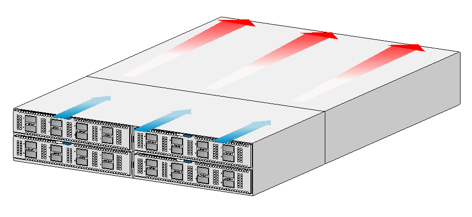
5 Cooling system
|
|
CAUTION: The chassis and power modules use separate air aisles. Make sure the two aisles are not blocked when the switch is operating. |
To dissipate heat timely and ensure system stability, the switch uses the front-rear air aisle cooling system. Consider the site ventilation design when you plan the installation site for the switch.
Table5-1 Cooling system for the switch
|
Switch model |
Available fan trays |
Airflow direction |
|
· S6850-56HF · S6850-2C · S9850-32H |
LSWM1FANSA LSWM1FANSA-SN |
From the power module side to the port side |
|
LSWM1FANSAB LSWM1FANSAB-SN |
From the port side to the power module side |
|
|
S9850-4C |
LSWM1BFANSC LSWM1BFANSC-SN |
From the power module side to the port side |
|
LSWM1BFANSCB LSWM1BFANSCB-SN |
From the port side to the power module side |
Figure5-1 Airflow from the power module side to the port side through the S6850-56HF chassis (with LSWM1FANSA fan trays)
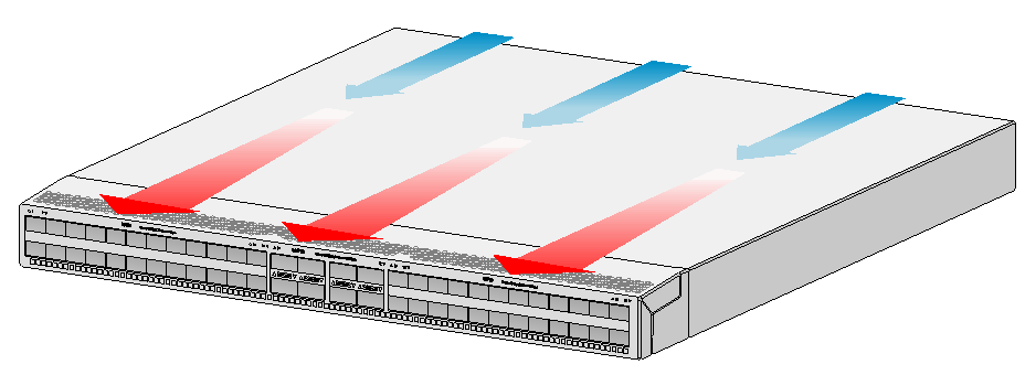
Figure5-2 Airflow from the port side to the power module side through the S6850-56HF chassis (with LSWM1FANSAB fan trays)
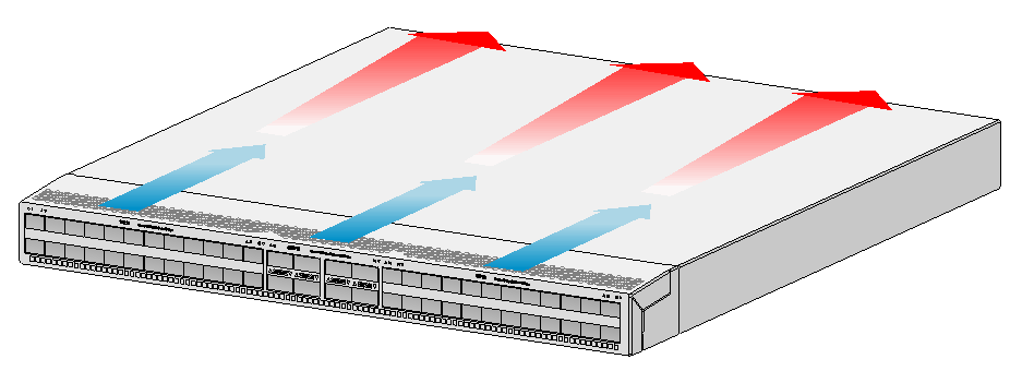
Figure5-3 Airflow from the power module side to the port side through the S9850-4C chassis (with LSWM1BFANSC fan trays)
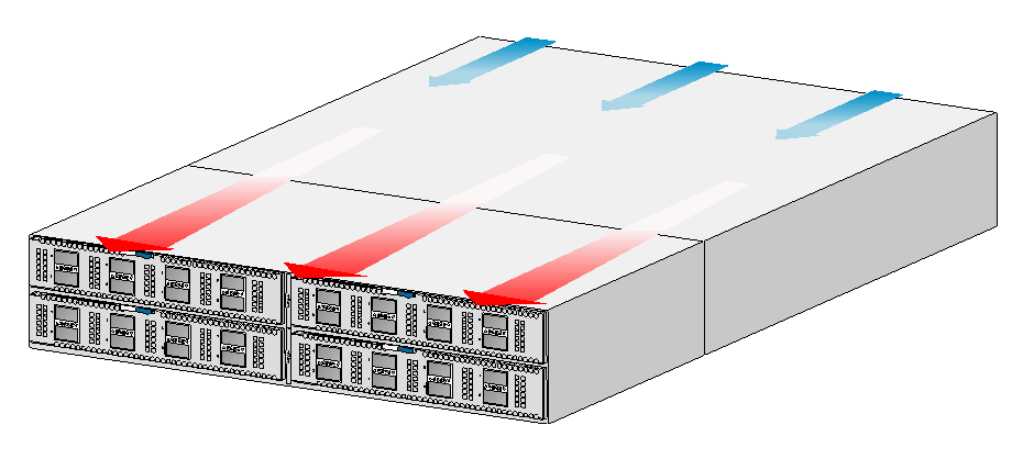
Figure5-4 Airflow from the port side to the power module side through the S9850-4C chassis (with LSWM1BFANSCB fan trays)