| Title | Size | Downloads |
|---|---|---|
| H3C Campus Switches PoE++ Technology White Paper-6W100-book.pdf | 121.40 KB |
- Table of Contents
- Related Documents
-
|
|
|
H3C Campus Switches |
|
PoE++ Technology White Paper |
|
|
|
|
Copyright © 2021 New H3C Technologies Co., Ltd. All rights reserved.
No part of this manual may be reproduced or transmitted in any form or by any means without prior written consent of New H3C Technologies Co., Ltd.
Except for the trademarks of New H3C Technologies Co., Ltd., any trademarks that may be mentioned in this document are the property of their respective owners.
This document provides generic technical information, some of which might not be applicable to your products.
The information in this document is subject to change without notice.
Overview
Technical background
Varieties of IP-based endpoints such as IP phones, access points, portable device chargers, card readers, and Webcams have been developed and widely used nowadays driven by fast development of network technologies. For these devices to run on the network, you must connect network cables to transmit data and deploy power sourcing devices to supply power to them. These power sourcing devices and power cords will not only cause higher expenditure but also increase device deployment and maintenance complexity.
Power over Ethernet (PoE), also known as remote power supply, is a technology that delivers power to powered devices (PDs) over twisted pair cables. It minimizes the costs while ensuring secure network operation without changing the network cabling.
The PoE++ technology, defined in the latest PoE standard 802.3bt, delivers a maximum power output of 90 W and is backward compatible with existing PoE standards, making it to fit various power needs.
Benefits
The PoE technology offers the following benefits:
· Highly available—PoE power comes from a single centralized point and not from distributed power supplies, enabling unified power management and convenient power backup.
· Easy to deploy—Network endpoints do not need a connection to an external power supply but a single network cable which will carry both data and power simultaneously.
· Standards compliant—This technology is defined in IEEE 802.3af standard, IEEE 802.3at standard, and IEEE 802.3bt standard and uses globally unified power interface to adapt to various PDs.
· Widely applicable—This technology is widely applicable to varieties of IP endpoints such as IP phones, access points, portable device chargers, card readers, and Webcams.
PoE standards
IEEE released 802.3af (PoE), 802.3at (PoE+), and 802.3bt (PoE++) standards in chronological sequence. These standards are backward compatible while forwards incompatible. 802.3af PoE, 802.3at PoE+, and 802.3bt PoE++ deliver a maximum PoE power of 15.4 W, 30 W, and 90 W, respectively. H3C supports a maximum power output of 99 W from a PoE++ port.
Table 1 Specifications of different PoE standards
|
Item |
PoE |
PoE+ |
PoE++ |
PoE++ |
|
Standard |
802.3af |
802.3at |
802.3bt |
802.3bt |
|
Power transmission distance |
100 m (328.08 ft) |
100 m (328.08 ft) |
100 m (328.08 ft) |
100 m (328.08 ft) |
|
Power classes |
0 to 3 |
4 |
5 and 6 |
7 and 8 |
|
PSE output voltage |
44 to 57 VDC |
50 to 57 VDC |
50 to 57 VDC |
52 to 57 VDC |
|
PSE output power |
≤ 15.4 W |
≤ 30 W |
≤ 60 W |
≤ 90 W |
|
PD input voltage |
36 to 57 VDC |
42.5 to 57 VDC |
42.5 to 57 VDC |
42.5 to 57 VDC |
|
PD max power |
12.95 W |
25.5 W |
51 W |
71 W |
|
Cable |
Ethernet cable |
CAT-5 or above |
CAT-5 or above |
CAT-5 or above |
|
Cable pairs to transmit power |
2 |
2 |
4 |
4 |
PoE implementation
PoE system
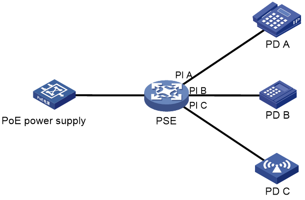
As shown in Figure 1, a PoE system includes the following elements:
· PoE power supply—A PoE power supply provides power for the entire PoE system.
· PSE—A power sourcing equipment (PSE) supplies power to PDs. PSE devices are classified into single-PSE devices and multiple-PSE devices.
¡ A single-PSE device has only one piece of PSE firmware.
¡ A multiple-PSE device has multiple PSEs. A multiple-PSE device uses PSE IDs to identify different PSEs. To view the mapping between the PSE ID and slot number, execute the display poe device command.
· PI—A power interface (PI) is a PoE-capable Ethernet interface on a PSE.
· PD—A powered device (PD) receives power from a PSE. PDs include IP telephones, APs, portable chargers, POS terminals, and Web cameras. You can also connect a PD to a redundant power source for reliability.
Figure 1 PoE system
PoE power delivery modes
PoE power can be delivered over data pairs or spare pairs of a twisted pair cable.
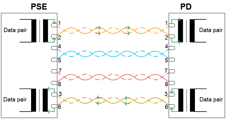
· Power delivery over data pairs (Alternative A)—A PSE uses data pairs (on pins 1, 2 and pins 3, 6) to transmit data and power to PDs. The PSE applies negative voltage to pair 1, 2 and positive voltage to pair 3 and 6, or positive voltage to pair 1 and 2 and negative voltage to pair 3 and 6. A 10BASE-T or 100BASETX interface uses pairs 1, 2 and 3, 6 to transmit data and a 1000BASE-T interface uses all the four pairs to transmit data. Because DC power and data frequencies do not interfere with each other, power and data can be transmitted over a same pair.
Figure 2 Power delivery over data pairs
· Power delivery over spare pairs (Alternative B)—A PSE transmits power to a PD over spare pairs (on pins 4, 5 and pins 7, 8). It applies positive voltage to pair 4, 5 and negative voltage to pair 7, 8.
Figure 3 Power delivery over spare pairs
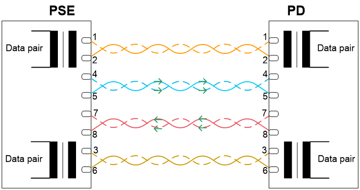
A PD must support both the power delivery modes. H3C PoE and PoE+ devices support power deliver over data pairs. H3C PoE++ devices support power delivery over data pairs and spare pairs and can use all the eight twisted pairs to transmit power.
PoE power delivery process
To ensure power safety, a PSE will have a detection of PDs before delivering power to PDs.
A PSE uses the following procedure to deliver power to PDs:
1. Detection of PDs
A PSE periodically outputs a small voltage with limited current from each PI to detect PD presence. The voltage is in the range of 2.8 V to 10 V, which will not damage a non-PoE device. If a resistance value is detected in the range of 19 KΩ to 26.5 KΩ, it is determined that a PD compliant with the IEEE 802.3af standard, IEEE 802.3at standard, or IEEE 802.3bt standard connects to the PI.
2. Classification of PDs
Upon detection of a PD, the PSE determines the power requirements of the PD and classifies it. Classification of PDs can be implemented through current detection or link layer discovery protocol (LLDP).
The available power classes vary by PoE standard:
¡ 802.3af—Defines four power classes 0 to 3 and delivers a maximum power of 12.95 W.
¡ 802.3at—Adds class 4 in addition to the four power classes defined by 802.3af and delivers a maximum power of 25.5 W.
¡ 802.3bt—Adds classes 5 to 8 in addition to the five power classes defined by 802.3at and delivers a maximum power of 71 W.
3. Power delivery to PDs
The PSE supplies stable power to each PD based on its power class.
4. Power removal from PDs
The PSE continuously monitors the current of PDs while delivery power to them and will cut off power to a PD if one of the following conditions is detected:
¡ The PD current drops below the minimum value.
¡ The PD current surges. This might occur when the PD is removed or rebooted, a PD power overload or short circuit occurs, or the required power exceeds the maximum capacity of the PSE.
Fast PoE
Typically, PIs does not deliver power to PDs the moment the PSE is powered on but wait until the PSE completes startup.
Fast PoE enables PIs to deliver power to PDs within few seconds after power is supplied to the PSE.
Only part of H3C PoE models support this feature. For switch compatibility with this feature, see the document for the switch.
Perpetual PoE
Perpetual PoE continuously monitors the PD states and ensures continued power supply to PDs even when the PSE device is hot rebooting.
AI-driven PoE
Innovatively integrating AI technologies into PoE switches, H3C AI-driven PoE enables completely automated, intelligently managed, healed, and optimized PoE, bringing convenient and outstanding PoE experience to users. Only part of H3C switch models support this feature. For switch compatibility with this feature, see the document for this switch.
Smart power management
AI-driven PoE adaptively adjusts the power supply parameters to fit power needs in various scenarios such as multiple types of PDs and address issues such as power supply failure and power interruption without human intervention.
The following describes how AI-driven PoE addresses power supply failure and power interruption without human intervention.
· Failure to supply power to a PD
After PoE is enabled on a port, the PSE chip sends PD detection signals. AI-driven PoE monitors the PD detection result in real time.
¡ If the system does not detect the PD, AI-driven PoE automatically adjusts the detection range, and the PSE chip relaxes the PD identification restrictions.
¡ If the system still does not detect the PD, AI-driven PoE automatically adjusts the detection algorithm and sampling and waveform parameters. Upon detection of the PD, the system immediately supplies power to it.
· Power interruption to a PD
AI-driven PoE monitors the power supply status of PIs in real time. If a PI loses power, it will monitor the LLDP information that the PI receives from its neighbor and the power supply status of the PSE.
¡ If no faults have occurred, it resumes power supply of the PI.
¡ If the PI has not received LLDP information from its neighbor for a long time but the PSE is operating correctly, it will automatically adjust relevant registers and reset PoE on the PI to re-power the PD.
¡ If a power failure is detected on the PSE, it automatically identifies the cause and makes adjustment accordingly.
- Instantaneous overcurrent—Automatically adjusts the inrush current limit of the PSE to allow large instantaneous currents.
- Smaller load current—Automatically adjusts the MPS current of the PSE to adapt to small loads.
- Higher load power—Automatically adjusts the power of the PSE and maximizes the PI power limit.
Priority-based power management
When the power demanded by PDs exceeds the power that can be supplied by the PoE switch, the system supplies power to PDs based on the PI priorities to ensure power supply to critical businesses and reduce power supply to PIs of lower priorities.
Smart power supply management
For a PoE switch with dual power supplies, AI-driven PoE can automatically calculate and regulate power output of each power supply based on the type and quantity of the power supply, to maximize the power usage of each power supply. When a power supply is removed, AI-driven PoE recalculates to preferentially guarantee power supply to PDs that are being powered.
Alarms and logs
AI-driven PoE constantly monitors the PoE running status continuously. If an exception occurs, it automatically analyzes, recovers, or even resets PoE, and outputs alarms and logs.
High PoE security
When an exception such as short circuit or circuit break occurs, AI-driven PoE immediately starts self-protection to protect the PoE switch from being damaged or burned.
PoE transmission distance
The PoE transmission distance depends on many factors including interface rate and network cable quality. Some PoE++ switches provide a maximum PoE transmission distance of 200 m (656.17 ft). The system adaptively adjusts the network bandwidth based on the transmission distance between a PSE and PD. When the transmission distance exceeds 100 m (328.08 ft), the system automatically decreases the port rate to reduce the line loss and ensure signal and power transmission quality.
H3C PoE++ campus switches
H3C S6520X switch series
H3C S6520X PoE switch models S6520X-26MC-UPWR-SI, S6520X-26XC-UPWR-SI, and S6520X-54XC-UPWR-SI support PoE, PoE+, and PoE++ that deliver a maximum power of 15.4 W, 30 W, and 60 or 90 W, respectively.
Table 2 H3C S6520X PoE switch models
|
PoE switch model |
Ports and slots |
|
S6520X-26XC-UPWR-SI |
· 24 × 10G/5G/2.5G/1000/100BASE-T autosensing Ethernet ports · 1 × interface module slot |
|
S6520X-54XC-UPWR-SI |
· 48 × 10G/5G/2.5G/1000/100BASE-T autosensing Ethernet ports · 4 × QSFP+ ports · 1 × interface module slot |
|
S6520X-26MC-UPWR-SI |
· 24 × 5G/2.5G/1000/100BASE-T autosensing Ethernet ports · 1 × interface module slot |
Table 3 Maximum PoE transmission distance of the multi-rate ports on H3C S6520X PoE switch models
|
PoE switch model |
Transmission rate |
Network cable type |
Maximum transmission distance |
|
S6520X-26XC-UPWR-SI S6520X-54XC-UPWR-SI |
10 Gbps |
CAT6 S/FTP or above |
100 m (328.08 ft) |
|
CAT6 UTP |
55 m (180.45 ft) |
||
|
CAT5e |
55 m (180.45 ft) |
||
|
5 Gbps |
CAT5e or above |
100 m (328.08 ft) |
|
|
2.5 Gbps |
CAT5e or above |
200 m (656.17 ft) |
|
|
1 Gbps |
CAT5e or above |
140 m (459.32 ft) |
|
|
100 Mbps |
CAT5e or above |
200 m (656.17 ft) |
|
|
S6520X-26MC-UPWR-SI |
5 Gbps |
CAT5e or above |
100 m (328.08 ft) |
|
2.5 Gbps |
CAT5e or above |
200 m (656.17 ft) |
|
|
1 Gbps |
CAT5e or above |
200 m (656.17 ft) |
|
|
100 Mbps |
CAT5e or above |
200 m (656.17 ft) |
|
|
NOTE: The maximum PoE transmission distance depends on many factors including the compliant PoE standard and power class of the PD and network cable quality. |
H3C S5130S switch series
H3C S5130S PoE switch models S5130S-10MS-UPWR-EI, S5130S-28S-UPWR-EI-Q, S5130S-16S-UPWR-EI-Q, and S5130S-28S-UPWR-HI support PoE, PoE+, and PoE++ that deliver a maximum power of 15.4 W, 30 W, and 60 or 90 W, respectively.
Table 4 H3C S5130S PoE switch models
|
PoE switch model |
Ports |
|
S5130S-10MS-UPWR-EI |
· 8 × 2.5G/1000/100BASE-T autosensing Ethernet ports · 2 × SFP+ ports |
|
S5130S-28S-UPWR-EI-Q |
· 24 × 1000/100/10 BASE-T autosensing Ethernet ports (The lowest-number eight ports support PoE++ and the highest-numbered sixteen ports support PoE+) · 4 × SFP+ ports |
|
S5130S-16S-UPWR-EI-Q |
· 12 × 1000/100/10 BASE-T autosensing Ethernet ports · 4 × SFP+ ports |
|
S5130S-28S-UPWR-HI |
· 24 × 1000/100/10 BASE-T autosensing Ethernet ports · 4 × SFP+ ports |
Table 5 Maximum PoE transmission distance of the multi-rate ports on H3C S5130S PoE switch models
|
PoE switch model |
Transmission rate |
Network cable type |
Maximum transmission distance |
|
S5130S-10MS-UPWR-EI |
2.5 Gbps |
CAT5e or above |
200 m (656.17 ft) |
|
1 Gbps |
CAT5e or above |
200 m (656.17 ft) |
|
|
100 Mbps |
CAT5e or above |
200 m (656.17 ft) |
|
|
S5130S-28S-UPWR-EI-Q |
1 Gbps |
CAT5e or above |
120 m (393.70 ft) |
|
100 Mbps |
CAT5e or above |
180 m (590.55 ft) |
|
|
10 Mbps |
CAT5e or above |
200 m (656.17 ft) |
|
|
S5130S-16S-UPWR-EI-Q |
1 Gbps |
CAT5e or above |
120 m (393.70 ft) |
|
100 Mbps |
CAT5e or above |
180 m (590.55 ft) |
|
|
10 Mbps |
CAT5e or above |
200 m (656.17 ft) |
|
|
S5130S-28S-UPWR-HI |
1 Gbps |
CAT5e or above |
120 m (393.70 ft) |
|
100 Mbps |
CAT5e or above |
180 m (590.55 ft) |
|
|
10 Mbps |
CAT5e or above |
200 m (656.17 ft) |
|
|
NOTE: The maximum PoE transmission distance depends on many factors including the compliant PoE standard and power class of the PD and network cable quality. |
References
· 802.3af-2003, IEEE Standard for Information Technology – Telecommunications and Information Exchange Between Systems – Local and Metropolitan Area Networks – Specific Requirements – Part 3: Carrier Sense Multiple Access with Collision Detection (CSMA/CD) Access Method and Physical Layer Specifications – Data Terminal Equipment (DTE) Power Via Media Dependent Interface (MDI)
· 802.3at-2009, IEEE Standard for Information technology – Local and metropolitan area networks-- Specific requirements – Part 3: CSMA/CD Access Method and Physical Layer Specifications Amendment 3: Data Terminal Equipment (DTE) Power via the Media Dependent Interface (MDI) Enhancements
· 802.3bt-2018, IEEE Standard for Ethernet Amendment 2: Physical Layer and Management Parameters for Power over Ethernet over 4 pairs
Appendix Acronyms
Table 6 Acronyms
|
Acronym |
Full English name |
|
PoE |
Power over Ethernet |
|
AP |
Access point |
|
PD |
Powered device |
|
PSE |
Power sourcing equipment |
|
PI |
Power interface |
|
LLDP |
Link layer discovery protocol |
